EP2180406A2 - Computersystem und Speicherverwendungseinstellungsprogramm - Google Patents
Computersystem und Speicherverwendungseinstellungsprogramm Download PDFInfo
- Publication number
- EP2180406A2 EP2180406A2 EP20090170309 EP09170309A EP2180406A2 EP 2180406 A2 EP2180406 A2 EP 2180406A2 EP 20090170309 EP20090170309 EP 20090170309 EP 09170309 A EP09170309 A EP 09170309A EP 2180406 A2 EP2180406 A2 EP 2180406A2
- Authority
- EP
- European Patent Office
- Prior art keywords
- memory
- use setting
- memory blocks
- data
- setting data
- Prior art date
- Legal status (The legal status is an assumption and is not a legal conclusion. Google has not performed a legal analysis and makes no representation as to the accuracy of the status listed.)
- Withdrawn
Links
Images




Classifications
-
- G—PHYSICS
- G06—COMPUTING OR CALCULATING; COUNTING
- G06F—ELECTRIC DIGITAL DATA PROCESSING
- G06F12/00—Accessing, addressing or allocating within memory systems or architectures
- G06F12/02—Addressing or allocation; Relocation
- G06F12/06—Addressing a physical block of locations, e.g. base addressing, module addressing, memory dedication
-
- G—PHYSICS
- G06—COMPUTING OR CALCULATING; COUNTING
- G06F—ELECTRIC DIGITAL DATA PROCESSING
- G06F11/00—Error detection; Error correction; Monitoring
- G06F11/008—Reliability or availability analysis
-
- G—PHYSICS
- G06—COMPUTING OR CALCULATING; COUNTING
- G06F—ELECTRIC DIGITAL DATA PROCESSING
- G06F11/00—Error detection; Error correction; Monitoring
- G06F11/07—Responding to the occurrence of a fault, e.g. fault tolerance
- G06F11/0703—Error or fault processing not based on redundancy, i.e. by taking additional measures to deal with the error or fault not making use of redundancy in operation, in hardware, or in data representation
- G06F11/0706—Error or fault processing not based on redundancy, i.e. by taking additional measures to deal with the error or fault not making use of redundancy in operation, in hardware, or in data representation the processing taking place on a specific hardware platform or in a specific software environment
- G06F11/073—Error or fault processing not based on redundancy, i.e. by taking additional measures to deal with the error or fault not making use of redundancy in operation, in hardware, or in data representation the processing taking place on a specific hardware platform or in a specific software environment in a memory management context, e.g. virtual memory or cache management
-
- G—PHYSICS
- G06—COMPUTING OR CALCULATING; COUNTING
- G06F—ELECTRIC DIGITAL DATA PROCESSING
- G06F11/00—Error detection; Error correction; Monitoring
- G06F11/07—Responding to the occurrence of a fault, e.g. fault tolerance
- G06F11/0703—Error or fault processing not based on redundancy, i.e. by taking additional measures to deal with the error or fault not making use of redundancy in operation, in hardware, or in data representation
- G06F11/0766—Error or fault reporting or storing
-
- G—PHYSICS
- G06—COMPUTING OR CALCULATING; COUNTING
- G06F—ELECTRIC DIGITAL DATA PROCESSING
- G06F12/00—Accessing, addressing or allocating within memory systems or architectures
- G06F12/02—Addressing or allocation; Relocation
- G06F12/0223—User address space allocation, e.g. contiguous or non contiguous base addressing
-
- G—PHYSICS
- G06—COMPUTING OR CALCULATING; COUNTING
- G06F—ELECTRIC DIGITAL DATA PROCESSING
- G06F12/00—Accessing, addressing or allocating within memory systems or architectures
- G06F12/14—Protection against unauthorised use of memory or access to memory
Definitions
- An ordinary computer system configured to diagnose a main memory, to detect a bad area in each of memory blocks into which an area of the main memory is divided by a certain length, and to identify a memory block in which a bad area is detected as a bad block is known, e.g., as disclosed in Patent document 1 and Patent Document 2.
- the computer system of this kind is configured not to allow use of an identified bad block, and to use a normal memory block only other than the bad block in the main memory.
- the computer system may not effectively use the whole main memory.
- a computer system including: a memory configured to store various kinds of data, a use setting data memory means for storing use setting data indicating a use of each of a plurality of memory blocks into which the memory is divided by a certain length, a memory diagnosis means for diagnosing the memory so as to detect a bad area in each of the memory blocks, and a memory use setting means for setting the use setting data of each of the memory blocks stored in the use setting data memory means in accordance with a result of detecting the bad area in each of the memory blocks by means of the memory diagnosis means.
- the computer system of the embodiment has a memory configured to store various kinds of data, a use setting data memory means for storing use setting data indicating a use of each of a plurality of memory blocks into which the memory is divided by a certain length, a memory diagnosis means for diagnosing the memory so as to detect a bad area in each of the memory blocks, and a memory use setting means for setting the use setting data of each of the memory blocks stored in the use setting data memory means in accordance with a result of detecting the bad area in each of the memory blocks by means of the memory diagnosis means.
- a main memory of the computer system of the embodiment such as a DRAM (dynamic random access memory)
- use setting data indicating the use of each of the memory blocks included in the main memory is stored in a use setting data memory means that is a non-volatile memory inside the computer system such as a flash memory.
- each of the memory blocks includes various uses such as a use for developing a certain program, a use for storing graphics data or voice data, and so on.
- the memory diagnosis means of the embodiment diagnoses the main memory so as to detect a bad area in each of the memory blocks before each of the memory blocks is assigned a use.
- the bad area is an area in each of the memory blocks having a bad bit on which a memory function such as reading and writing data does not properly work.
- the memory block including a bad area includes a plurality of bad blocks of different number of bad bits from a slightly bad block of a relatively small number of bad bits to a severely bad block of a relatively large number of bad bits. Even in a case where the bad block is slightly bad, it is not preferable to use the slightly bad block as an area in which a program and so on is developed from a viewpoint of making sure that the program normally works.
- the slightly bad block as an area in which graphics data or voice data is stored. That is based on empirical knowledge that, even if a bad block exists in a memory block for storing graphics data or voice data but the number of bad bits included in the bad block is small, reproducing an image or voice by actually using the graphics or voice data by means of various devices does not cause quality degradation of the image or voice.
- the memory use setting means of the embodiment is configured to set use setting data of each of the memory blocks stored in the use setting data memory means in accordance with a result of detecting the bad area in each of the memory blocks by means of the memory diagnosis means.
- each of the memory blocks including the bad block may be assigned a proper use without preventing the bad block from being used.
- the use setting data indicating the use of each of the memory blocks, into which the memory area is divided by a certain length, is stored in the non-volatile memory.
- the memory is diagnosed so that a bad area is detected in each of the memory blocks.
- the use setting data of each of the memory blocks stored in the non-volatile memory is set in accordance with a result of detecting a bad area in each of the memory blocks.
- the computer system of the embodiment is configured as described above, the computer system may assign a proper use not only to a normal memory block of the main memory but also to a slightly bad block in which the number of bad bits is relatively small, so as to effectively use each of the memory blocks included in the main memory.
- the memory diagnosis means and the memory use setting means may be implemented by, e.g., a BIOS program that the CPU reads from the ROM and runs upon the computer system being activated.
- Fig. 1 is a functional block diagram illustrating a configuration of a computer system 1 of the embodiment.
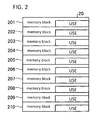
- Fig. 2 illustrates in detail a DRAM illustrated in Fig. 1 .
- the computer system 1 has a CPU (central processing unit) 10, a DRAM 20, a non-volatile memory 30, a ROM 40, a graphics controller 50, a sound controller 60 and a bus 70 connecting the above portions one another.
- CPU central processing unit
- the CPU 10 is an arithmetic device configured to perform various processes. More specifically, the CPU 10 reads from the ROM 40 and runs a BIOS (basic input output system) program 41 which will be described later upon the computer system 1 being activated, so as to check whether each kind of device such as the DRAM 20 has a defect. Moreover, the CPU 10 runs the BIOS program 41 so as to activate an OS (operating system) and to control each kind of device. The CPU 10 runs the BIOS program 41 so as to perform a memory use setting process for setting uses of memory blocks 201-210 (illustrated in Fig. 2 ).
- BIOS basic input output system
- the DRAM 20 is a main memory (primary memory device) of the computer system 1. More specifically, the DRAM 20 is used as a working memory in which a program (including the BIOS program 41) run by the CPU 10 is developed, or various data such as graphics data or voice data is temporarily stored. Moreover, as the DRAM 20 is used as the working memory of the CPU 10, the DRAM 20 is managed for each of the memory blocks 201-210 into which the area of the DRAM 20 is divided by a certain length, as illustrated in Fig. 2 .
- the BIOS program 41 run by the CPU 10 assigns each of the memory blocks 201-210 various kinds of uses as described later.
- the uses of the memory blocks 201-210 include various kinds of uses such as a use of developing a certain program, a use of developing graphics data or voice data and so on.
- the non-volatile memory 30 is a rewritable and non-volatile storage medium such as a flash memory.
- the non-volatile memory 30 stores use setting data 31 indicating a use of each of the memory blocks 201-210 into which the area of the DRAM 20 is divided by a certain length, and works as a use setting data memory means.
- the use setting data 31 will be explained later in detail.
- the ROM 40 stores various programs run by the CPU 10, data to be used for running the programs and so on. More specifically, the ROM 40 stores the BIOS program 41 that the CPU 10 reads and runs upon the computer system 1 being activated, and so on. Moreover, the ROM 40 stores a use setting table 42 that the CPU 10 uses for running the BIOS program 41. Moreover, the ROM 40 stores default use setting data 43 that presets a use of each of the memory blocks 201-210, and so on, so as to work as a default use memory means. The use setting table 42 and the default use setting data 43 will be explained later in detail.
- the BIOS program 41 is a basic input output system. More specifically, the BIOS program 41 is activated upon power supplied to the computer system 1 being turned on, and is a control program for controlling the OS, application programs, and data input and output to and from the DRAM 20 and peripheral devices (a display, a keyboard and so on). Moreover, the BIOS program 41 is run by the CPU 10 so as to perform the memory use setting process for setting a use of each of the memory blocks 201-210 of the DRAM 20.
- the graphics controller 50 generates graphics data as directed by the CPU 10 and stores the graphics data in a memory block for graphics in the DRAM 20. Moreover, the graphics controller 50 reads the graphics data stored in the memory block for graphics in the DRAM 20 and displays graphics on a display device (not illustrated).
- the sound controller 60 generates voice data as directed by the CPU 10 and stores the voice data in a memory block for voice in the DRAM 20. Moreover, the sound controller 60 reads the voice data stored in the memory block for voice in the DRAM 20 and produces voice output through a speaker (not illustrated).
- FIG. 3 is a functional block diagram illustrating details of the BIOS program 41 illustrated in Fig. 1 .
- functions implemented upon the CPU 10 running the BIOS program 41 stored in the ROM 40 are illustrated as functional blocks.
- the BIOS program 41 has functional units which are a memory diagnosis unit 411 and a memory use setting unit 412. Each of the functional units 411 and 412 starts working upon the BIOS program being activated (being run).
- the memory diagnosis unit 411 diagnoses the DRAM 20 so as to detect a bad area in each of the memory blocks 201-210.
- the bad area means an area in an individual memory block having a bad bit on which a memory function such as reading and writing data does not properly work. Detection of the bad area in each of the memory blocks by means of the memory diagnosis unit 411 includes detection of the number of bad bits included in the bad area.
- the memory use setting unit 412 sets the use setting data 31 of each of the memory blocks 201-210 to be stored in the non-volatile memory 30 in accordance with a result of detecting the bad area in each of the memory blocks by means of the memory diagnosis unit 411. More specifically, the memory use setting unit 412 sets the use setting data 31 to be stored in the non-volatile memory 30 by using the use setting table 42 stored in the ROM 40.
- the CPU 10 references the use setting data 31 set by the memory use setting unit 412, and assigns a use to each of the memory blocks 201-210 on the basis of the use setting data 31.
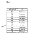
- Fig. 4 illustrates in detail the use setting data 31 illustrated in Fig. 1 .
- Fig. 5 illustrates in detail the use setting table 42 illustrated in Fig. 1 .
- the use setting data 31 stored in the non-volatile memory 30 indicates a use of each of the memory blocks 201-210 in the DRAM 20.
- the use setting data 31 includes the use of each of the memory blocks 201-210 written on an address of each of the memory blocks.
- the memory block 201 is assigned a use "for programs", which indicates that the memory block 201 is used as a memory block for programs in which a certain program is developed.
- the memory blocks 203-205 are assigned uses "for graphics”, which indicates that the memory blocks 203-205 are used as memory blocks for graphics data for storing graphics data.
- the memory block 207 is assigned a use "for voice”, which indicates that the memory block 207 is used as a memory block for voice for storing voice data.
- the default use setting data 43 illustrated in Fig. 1 presets a use of each of the memory blocks 201-210 in the DRAM 20, and gives initial (default) values of the use setting data 31.
- the default use setting data 43 includes, similarly as the use setting data 31, the use of each of the memory blocks 201-210 written on an address of each of the memory blocks.
- the use setting table 42 stored in the ROM 40 is a table including a memory quality level indicating quality of an individual memory block in the DRAM 20 and the use of the individual memory block associated with each other.
- the memory quality level of an individual memory block in the DRAM 20 is specified by the number of bad bits included in the memory block, and is divided into three levels 1-3.
- the memory quality level "level 1" indicates that the memory block includes multiple bad bits.
- the memory quality level “level 2” indicates that the memory block includes a single bad bit.
- the memory quality level “level 3” indicates that the memory block includes no bad bits at all, i.e., the memory block is normal.
- the use setting table 42 illustrated in Fig. 5 indicates that, if the memory quality level of the memory block is "level 1", the use of the memory block is set (changed) to the use for voice. It is indicated that, if the memory quality level of the memory block is "level 2", the use of the memory block is changed to the use for graphics data. It is indicated that, if the memory quality level of the memory block is "level 3", the use of the memory block is changed to the use for programs.
- the memory quality level of the memory block for voice is lower than the memory quality level of the memory block for graphics, as noise of voice is hardly perceived by a person in comparison with noise of graphics (an image) in a case where the bad bit of the memory block causes such noise in the data.
- the memory use setting unit 412 sets the use setting data 31 corresponding to the memory block in which the bad area including the multiple bad bits is detected (called a multiple-bad-bit block hereafter) to indicate that the memory block is used as a memory block for voice for storing voice data. That is, the memory use setting unit 412 changes the use of the multiple-bad-bit block to the use for voice with reference to the use setting table 42.
- the memory use setting unit 412 sets the use setting data 31 corresponding to the memory block in which the bad area including the single bad bit is detected in the DRAM 20 (called a single-bad-bit block hereafter) to indicate that the memory block is used as a memory block for image data for storing image data. That is, the memory use setting unit 412 changes the use of the single-bad-bit block to the use for image data with reference to the use setting table 42.
- the memory use setting unit 412 sets the use setting data 31 corresponding to the memory block in which no bad area is detected at all in the DRAM 20 (normal block) to indicate that the memory block is used as a memory block for programs for developing a certain program. That is, the memory use setting unit 412 changes the use of the normal block to the use for programs with reference to the use setting table 42.
- the above functional units 411 and 412 start their processes upon the computer system 1 being activated, and more specifically, upon the BIOS program 41 being activated.
- the use setting data 31 is already set for each of the memory blocks 201-210 before the process starts, it is allowable that the use setting data 31 is not set in accordance with a result of detecting a bad area in each of the memory blocks by means of the memory diagnosis unit 411.
- the BIOS program 41 sets a use to each of the memory blocks 201-210 by means of the memory use setting unit 411 after being activated the last time, the BIOS program 41 may omit the memory diagnosis unit 411 and the memory use setting unit 412 from working upon being activated next.
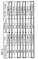
- Fig. 6 illustrates an example of the procedure in which the memory use setting unit 412 sets the use setting data 31.
- Fig. 6 illustrates a case where the use setting data 31 illustrated in Fig. 4 is changed. It is assumed, in the use setting data 31 illustrated in Fig. 4 , that the uses of three memory blocks 203-205 are preset to the use for programs, and that the use of one memory block 207 is preset to the use for voice.
- the memory use setting unit 412 sets (changes) the use of the memory block 210 from “ for programs" to "for voice” with reference to the use setting table 42 illustrated in Fig. 5 .
- the memory diagnosis unit 411 diagnoses the memory quality level of the memory block 202 as "level 2”
- the memory use setting unit 412 changes the use of the memory block 202 from " for programs" to "for graphics”.
- the memory blocks "for voice” and the memory blocks “for graphics” each increase by one, the memory blocks "for programs” decrease by two.
- the memory use setting unit 412 changes the uses of two memory blocks 205 and 207, for which the memory quality level is diagnosed as "level 3" by the memory diagnosis unit 411, from “for graphics " and “for voice " to "for programs", respectively.
- the DRAM 20 may thereby be compensated for the decrease of the memory blocks for programs, and each of the memory blocks included in the DRAM 20 may be effectively used.
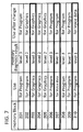
- Fig. 7 illustrates another example of the procedure in which the memory use setting unit 412 sets the use setting data 31.
- Fig. 7 illustrates a case where the use setting data 31 illustrated in Fig. 4 is changed.
- the memory use setting unit 412 changes the use of the memory block 202 from “for programs” to "for graphics" with reference to the use setting table 42 illustrated in Fig. 5 .
- the memory diagnosis unit 411 diagnoses the memory quality level of the memory block 204 as "level 2”
- the memory use setting unit 412 maintains the use of the memory block 20 "for graphics”.
- the memory diagnosis unit 411 diagnoses the memory quality level of the memory block 203 as "level 3"
- the memory use setting unit 412 supposedly changes the use of the memory block 203 from "for graphics" to "for programs”.
- the memory block 202 of the memory quality level "level 2" and the memory block 204 of the memory quality level “level 2" are not adjacent to each other. That is a case where the memory diagnosis unit 411 detects a plurality of memory blocks having bad areas (memory blocks 202 and 204 in the above case) and the plural memory blocks having the bad areas are arranged on addresses which are not adjacent to each other.
- the memory use setting unit 412 exceptionally sets the use setting data 31 corresponding to another memory block existing between the above memory blocks to indicate that the memory block is used as a memory block for graphics. As illustrated in Fig. 7 , e.g., the memory use setting unit 412 sets the uses of the memory blocks 202 and 204, and of the memory block 203 existing between the two memory blocks 202 and 204, equally to "for graphics".
- the memory diagnosis unit 411 detects a plurality of the memory blocks of the memory quality level "level 2" (single-bad-bit blocks) and the plural single-bad-bit blocks are not adjacent to one another, as described above, the memory use setting unit 412 changes in the DRAM 20 the plural single-bad-bit blocks and a memory block existing between the plural single-bad-bit blocks to the memory blocks for "graphics".
- the computer system 1 may store the graphics data in a continuous area formed by a plurality of the memory blocks, and may reduce time for reading and writing the graphics data.
- Fig. 8 is a flowchart illustrating the memory use setting process of the computer system 1 illustrated in Fig. 1 .
- the CPU 10 reads from the ROM 40 and runs the BIOS program 41 after the power supplied to the computer system 1 is turned on so that the memory use setting process illustrated in Fig. 8 is performed.
- the BIOS program 41 first judges whether the use setting data 31 set (changed) by the memory use setting unit 412 is stored in the non-volatile memory 30 (step S10).
- step S10: Yes upon judging that the use setting data 31 changed by the memory use setting unit 412 is stored in the non-volatile memory 30 (step S10: Yes), that is, upon judging that a use is set to each of the memory blocks 201-210 by the memory use setting unit 412 after being activated the last time, the BIOS program 41 forwards the process to a step S16. Meanwhile, as a result of the judgment, upon judging that the use setting data 31 set by the memory use setting unit 412 is not stored in the non-volatile memory 30 (step S10: No), the BIOS program 41 forwards the process to a step S11.
- the memory diagnosis unit 411 of the BIOS program 41 diagnoses each one of all the memory blocks 201-210 so as to detect a bad area in each of the memory blocks 201-210 (step S11).
- the memory diagnosis unit 411 performs a process for relating a memory diagnosis result of detecting a bad area in each of the memory blocks 201-210 to the address data of each of the memory blocks 201-210 in the DRAM 20 (step S12).
- the memory diagnosis unit 411 judges whether there is a memory block that has not been diagnosed in the DRAM 20 (step S13). So as to make the above judgment, the memory diagnosis unit 411 judges whether a memory diagnosis result is related to the address data of each of the memory blocks 201-210 of the DRAM 20. Upon judging that there is a memory block that has not been diagnosed in the DRAM 20 (step S13: Yes), the memory diagnosis unit 411 repeats the process from S11 to S13 until there is no memory block that has not been diagnosed in the DRAM 20.
- the memory diagnosis unit 411 judges whether a bad area is detected in each of the memory blocks 201-210 in the DRAM 20 (step S14). As a result of the judgment, upon judging that a bad area was detected in at least one of the memory blocks 201-210 in the DRAM 20 (step S14: Yes), the memory diagnosis unit 411 forwards the process to a step S15.
- the memory use setting unit 412 sets (changes) the use setting data 31 stored in the ROM 40 with reference to the use setting table 42 (step S15), and forwards the process to a step S17.
- the memory diagnosis unit 411 forwards the process to a step S16.
- the memory use setting unit 412 sets (changes) the use setting data 31 stored in the ROM 40 on the basis of the default use setting data 43 stored in the non-volatile memory 30 (step S16), and forwards the process to the step S17. That is, the default use setting data 43 is copied into the use setting data 31 as a default value at the step S16.
- the BIOS program 41 assigns a use to each of the memory blocks 201-210 on the basis of the use setting data 31 set at the step S15 or S16, and ends the memory use setting process.
- the use setting data 31 which indicates a use of each of the memory blocks 201-210 into which the area of the DRAM 20 of the embodiment is divided by a certain length, is stored in the non-volatile memory 30.
- the DRAM 20 is diagnosed so that a bad area is detected in each of the memory blocks 201-210.
- the use setting data of each of the memory blocks 201-210 stored in the non-volatile memory 30 is set in accordance with a result of detecting a bad area in each of the memory blocks 201-210.
- a bad block is set as a graphics memory (memory block for image data), and a normal block is set as a main memory in which a program resides (memory block for a program).
- a bad block is used as a portion of the memory so that the memory may be effectively used.
- the computer system assign a proper use not only to a normal memory block of the main memory but also to a slightly bad block in which the number of bad bits is relatively small, so as to effectively use each of the memory blocks included in the main memory.
- the BIOS program 41 of the embodiment is not limited to the one stored in the ROM 40, and may be stored in a rewritable non-volatile memory such as a flash memory so that the CPU 10 reads and runs the program. Moreover, the BIOS program 41 of the embodiment may be downloaded from a server connected to a network to the flash memory, or further may be recorded on a record medium such as a CD-ROM and loaded to the flash memory through a drive of the record medium.
Landscapes
- Engineering & Computer Science (AREA)
- Theoretical Computer Science (AREA)
- Physics & Mathematics (AREA)
- General Engineering & Computer Science (AREA)
- General Physics & Mathematics (AREA)
- Quality & Reliability (AREA)
- Computer Security & Cryptography (AREA)
- Techniques For Improving Reliability Of Storages (AREA)
- For Increasing The Reliability Of Semiconductor Memories (AREA)
- Memory System (AREA)
Applications Claiming Priority (1)
| Application Number | Priority Date | Filing Date | Title |
|---|---|---|---|
| JP2008258975A JP5439788B2 (ja) | 2008-10-03 | 2008-10-03 | コンピュータ装置、及びメモリ用途設定プログラム |
Publications (2)
| Publication Number | Publication Date |
|---|---|
| EP2180406A2 true EP2180406A2 (de) | 2010-04-28 |
| EP2180406A3 EP2180406A3 (de) | 2010-08-25 |
Family
ID=41832907
Family Applications (1)
| Application Number | Title | Priority Date | Filing Date |
|---|---|---|---|
| EP20090170309 Withdrawn EP2180406A3 (de) | 2008-10-03 | 2009-09-15 | Computersystem und Speicherverwendungseinstellungsprogramm |
Country Status (6)
| Country | Link |
|---|---|
| US (1) | US8239712B2 (de) |
| EP (1) | EP2180406A3 (de) |
| JP (1) | JP5439788B2 (de) |
| KR (1) | KR101125411B1 (de) |
| CN (1) | CN101714121B (de) |
| TW (1) | TWI434174B (de) |
Cited By (1)
| Publication number | Priority date | Publication date | Assignee | Title |
|---|---|---|---|---|
| EP2431881A4 (de) * | 2009-08-28 | 2012-12-26 | Artek Microelectronics Co Ltd | Verfahren und vorrichtung für die zuweisung eines sekundärspeichers |
Families Citing this family (1)
| Publication number | Priority date | Publication date | Assignee | Title |
|---|---|---|---|---|
| JP2012038368A (ja) * | 2010-08-04 | 2012-02-23 | Toshiba Corp | 不良解析装置及び不良解析方法 |
Citations (2)
| Publication number | Priority date | Publication date | Assignee | Title |
|---|---|---|---|---|
| JPH0520207A (ja) | 1991-07-16 | 1993-01-29 | Canon Inc | 画像メモリ装置 |
| JPH0537969A (ja) | 1991-07-31 | 1993-02-12 | Hitachi Ltd | 画像データのエラー監視方式 |
Family Cites Families (16)
| Publication number | Priority date | Publication date | Assignee | Title |
|---|---|---|---|---|
| US4380066A (en) * | 1980-12-04 | 1983-04-12 | Burroughs Corporation | Defect tolerant memory |
| JPH06202962A (ja) * | 1992-12-29 | 1994-07-22 | Brother Ind Ltd | 半導体メモリの管理システム |
| JP4246812B2 (ja) * | 1997-06-12 | 2009-04-02 | パナソニック株式会社 | 半導体回路及びその制御方法 |
| US6505305B1 (en) * | 1998-07-16 | 2003-01-07 | Compaq Information Technologies Group, L.P. | Fail-over of multiple memory blocks in multiple memory modules in computer system |
| JP2000132987A (ja) * | 1998-10-28 | 2000-05-12 | Neucore Technol Inc | 不揮発性半導体メモリ装置 |
| US6405323B1 (en) * | 1999-03-30 | 2002-06-11 | Silicon Storage Technology, Inc. | Defect management for interface to electrically-erasable programmable read-only memory |
| US6763425B1 (en) * | 2000-06-08 | 2004-07-13 | Netlogic Microsystems, Inc. | Method and apparatus for address translation in a partitioned content addressable memory device |
| US6781898B2 (en) * | 2002-10-30 | 2004-08-24 | Broadcom Corporation | Self-repairing built-in self test for linked list memories |
| KR100719380B1 (ko) * | 2006-03-31 | 2007-05-18 | 삼성전자주식회사 | 향상된 신뢰성 특성을 갖는 다치 플래시 메모리 장치 및그것을 포함한 메모리 시스템 |
| US7275190B2 (en) * | 2004-11-08 | 2007-09-25 | Micron Technology, Inc. | Memory block quality identification in a memory device |
| KR100722658B1 (ko) * | 2005-02-14 | 2007-05-28 | 최명렬 | 메모리 장치 및 그 제어 방법 |
| CN100407336C (zh) * | 2005-11-22 | 2008-07-30 | 武汉国光通信有限公司 | 一种嵌入式系统中非易失性存储器的数据存取方法 |
| JP4129693B2 (ja) * | 2006-05-18 | 2008-08-06 | コニカミノルタビジネステクノロジーズ株式会社 | メモリ管理方法 |
| KR20080010965A (ko) * | 2006-07-28 | 2008-01-31 | 엠텍비젼 주식회사 | 메모리 장치 및 메모리 장치의 불량블록 관리 방법 |
| KR20080018071A (ko) * | 2006-08-23 | 2008-02-27 | 슬림디스크 주식회사 | 컨텐츠 기록 장치 및 그 방법 |
| US20080189481A1 (en) * | 2007-02-07 | 2008-08-07 | Peter Mayer | Methods and systems for storing data based on a reliability requirement |
-
2008
- 2008-10-03 JP JP2008258975A patent/JP5439788B2/ja not_active Expired - Fee Related
-
2009
- 2009-09-15 EP EP20090170309 patent/EP2180406A3/de not_active Withdrawn
- 2009-09-15 TW TW098131047A patent/TWI434174B/zh not_active IP Right Cessation
- 2009-09-29 CN CN2009101791362A patent/CN101714121B/zh not_active Expired - Fee Related
- 2009-09-30 KR KR1020090093107A patent/KR101125411B1/ko not_active Expired - Fee Related
- 2009-09-30 US US12/570,054 patent/US8239712B2/en not_active Expired - Fee Related
Patent Citations (2)
| Publication number | Priority date | Publication date | Assignee | Title |
|---|---|---|---|---|
| JPH0520207A (ja) | 1991-07-16 | 1993-01-29 | Canon Inc | 画像メモリ装置 |
| JPH0537969A (ja) | 1991-07-31 | 1993-02-12 | Hitachi Ltd | 画像データのエラー監視方式 |
Cited By (1)
| Publication number | Priority date | Publication date | Assignee | Title |
|---|---|---|---|---|
| EP2431881A4 (de) * | 2009-08-28 | 2012-12-26 | Artek Microelectronics Co Ltd | Verfahren und vorrichtung für die zuweisung eines sekundärspeichers |
Also Published As
| Publication number | Publication date |
|---|---|
| CN101714121A (zh) | 2010-05-26 |
| TWI434174B (zh) | 2014-04-11 |
| US20100088559A1 (en) | 2010-04-08 |
| JP5439788B2 (ja) | 2014-03-12 |
| EP2180406A3 (de) | 2010-08-25 |
| JP2010092126A (ja) | 2010-04-22 |
| TW201015312A (en) | 2010-04-16 |
| KR101125411B1 (ko) | 2012-03-27 |
| US8239712B2 (en) | 2012-08-07 |
| CN101714121B (zh) | 2012-04-04 |
| KR20100038151A (ko) | 2010-04-13 |
Similar Documents
| Publication | Publication Date | Title |
|---|---|---|
| US6976197B2 (en) | Apparatus and method for error logging on a memory module | |
| JP2010092127A (ja) | コンピュータ装置、プロセッサ診断方法、及びプロセッサ診断制御プログラム | |
| JP5063152B2 (ja) | 代替ページのプールを使用してdma書込みページ障害をコンピュータにより管理するための方法、装置、及びコンピュータ・プログラム | |
| US20090271603A1 (en) | Embedded system and startup method thereof | |
| JP2012128643A (ja) | メモリシステム | |
| JP5401903B2 (ja) | 故障情報監視装置及び故障情報監視方法 | |
| JP5293062B2 (ja) | コンピュータ装置、メモリ診断方法、及びメモリ診断制御プログラム | |
| JP2000105694A (ja) | フラッシュメモリ、フラッシュメモリを備えたマイクロコンピュータおよびフラッシュメモリへのプログラム格納方法 | |
| WO2017080225A1 (zh) | 数据分区的修复方法、装置及终端 | |
| US8239712B2 (en) | Computer system and memory use setting program | |
| JP4668556B2 (ja) | タスク管理システム | |
| CN105700976A (zh) | 一种软磁盘阵列系统异常处理机制检测方法和装置 | |
| JP2007207014A (ja) | 電子装置および保守情報の採取方法 | |
| JP7135403B2 (ja) | ダンプ処理装置及び画像形成装置 | |
| CN103514056A (zh) | 显卡故障处理系统及方法 | |
| JP2009157649A (ja) | 命令チェックプログラム、命令チェック方法、命令チェック装置およびi/oシミュレータ | |
| CN113470725A (zh) | 一种动态随机存储器的测试方法及装置 | |
| JP2008250671A (ja) | 情報処理装置および情報処理方法 | |
| JP2002244934A (ja) | メモリ監視装置および方法 | |
| JP2003150458A (ja) | 障害検出装置、障害検出方法、プログラム及びプログラム記録媒体 | |
| JP3499184B2 (ja) | メモリのアドレスライン障害検出装置、その方法、及び記録媒体 | |
| JP2006276965A (ja) | 不良ブロック検出方法および不良ブロック検出装置 | |
| CN115098296A (zh) | 优化固态硬盘弱块验证的方法、装置、计算机设备及存储介质 | |
| US20070179635A1 (en) | Method and article of manufacure to persistently deconfigure connected elements | |
| JP2007323167A (ja) | メモリテスト方法 |
Legal Events
| Date | Code | Title | Description |
|---|---|---|---|
| PUAI | Public reference made under article 153(3) epc to a published international application that has entered the european phase |
Free format text: ORIGINAL CODE: 0009012 |
|
| AK | Designated contracting states |
Kind code of ref document: A2 Designated state(s): AT BE BG CH CY CZ DE DK EE ES FI FR GB GR HR HU IE IS IT LI LT LU LV MC MK MT NL NO PL PT RO SE SI SK SM TR |
|
| AX | Request for extension of the european patent |
Extension state: AL BA RS |
|
| PUAL | Search report despatched |
Free format text: ORIGINAL CODE: 0009013 |
|
| AK | Designated contracting states |
Kind code of ref document: A3 Designated state(s): AT BE BG CH CY CZ DE DK EE ES FI FR GB GR HR HU IE IS IT LI LT LU LV MC MK MT NL NO PL PT RO SE SI SK SM TR |
|
| AX | Request for extension of the european patent |
Extension state: AL BA RS |
|
| RIC1 | Information provided on ipc code assigned before grant |
Ipc: G06F 11/00 20060101ALI20100722BHEP Ipc: G06F 12/02 20060101AFI20100722BHEP |
|
| 17P | Request for examination filed |
Effective date: 20110221 |
|
| 17Q | First examination report despatched |
Effective date: 20150324 |
|
| STAA | Information on the status of an ep patent application or granted ep patent |
Free format text: STATUS: EXAMINATION IS IN PROGRESS |
|
| GRAP | Despatch of communication of intention to grant a patent |
Free format text: ORIGINAL CODE: EPIDOSNIGR1 |
|
| STAA | Information on the status of an ep patent application or granted ep patent |
Free format text: STATUS: GRANT OF PATENT IS INTENDED |
|
| RIC1 | Information provided on ipc code assigned before grant |
Ipc: G06F 12/02 20060101AFI20180221BHEP Ipc: G06F 11/07 20060101ALI20180221BHEP |
|
| INTG | Intention to grant announced |
Effective date: 20180319 |
|
| STAA | Information on the status of an ep patent application or granted ep patent |
Free format text: STATUS: THE APPLICATION IS DEEMED TO BE WITHDRAWN |
|
| 18D | Application deemed to be withdrawn |
Effective date: 20180731 |