EP2180214A1 - Dichtungsvorrichtung für Getriebegehäuse - Google Patents
Dichtungsvorrichtung für Getriebegehäuse Download PDFInfo
- Publication number
- EP2180214A1 EP2180214A1 EP09013417A EP09013417A EP2180214A1 EP 2180214 A1 EP2180214 A1 EP 2180214A1 EP 09013417 A EP09013417 A EP 09013417A EP 09013417 A EP09013417 A EP 09013417A EP 2180214 A1 EP2180214 A1 EP 2180214A1
- Authority
- EP
- European Patent Office
- Prior art keywords
- sealing device
- grease
- rotary shaft
- bearing
- gear chamber
- Prior art date
- Legal status (The legal status is an assumption and is not a legal conclusion. Google has not performed a legal analysis and makes no representation as to the accuracy of the status listed.)
- Withdrawn
Links
Images
Classifications
-
- B—PERFORMING OPERATIONS; TRANSPORTING
- B25—HAND TOOLS; PORTABLE POWER-DRIVEN TOOLS; MANIPULATORS
- B25F—COMBINATION OR MULTI-PURPOSE TOOLS NOT OTHERWISE PROVIDED FOR; DETAILS OR COMPONENTS OF PORTABLE POWER-DRIVEN TOOLS NOT PARTICULARLY RELATED TO THE OPERATIONS PERFORMED AND NOT OTHERWISE PROVIDED FOR
- B25F5/00—Details or components of portable power-driven tools not particularly related to the operations performed and not otherwise provided for
- B25F5/02—Construction of casings, bodies or handles
-
- F—MECHANICAL ENGINEERING; LIGHTING; HEATING; WEAPONS; BLASTING
- F16—ENGINEERING ELEMENTS AND UNITS; GENERAL MEASURES FOR PRODUCING AND MAINTAINING EFFECTIVE FUNCTIONING OF MACHINES OR INSTALLATIONS; THERMAL INSULATION IN GENERAL
- F16C—SHAFTS; FLEXIBLE SHAFTS; ELEMENTS OR CRANKSHAFT MECHANISMS; ROTARY BODIES OTHER THAN GEARING ELEMENTS; BEARINGS
- F16C33/00—Parts of bearings; Special methods for making bearings or parts thereof
- F16C33/72—Sealings
- F16C33/76—Sealings of ball or roller bearings
-
- F—MECHANICAL ENGINEERING; LIGHTING; HEATING; WEAPONS; BLASTING
- F16—ENGINEERING ELEMENTS AND UNITS; GENERAL MEASURES FOR PRODUCING AND MAINTAINING EFFECTIVE FUNCTIONING OF MACHINES OR INSTALLATIONS; THERMAL INSULATION IN GENERAL
- F16H—GEARING
- F16H57/00—General details of gearing
- F16H57/04—Features relating to lubrication or cooling or heating
- F16H57/042—Guidance of lubricant
- F16H57/0427—Guidance of lubricant on rotary parts, e.g. using baffles for collecting lubricant by centrifugal force
-
- F—MECHANICAL ENGINEERING; LIGHTING; HEATING; WEAPONS; BLASTING
- F16—ENGINEERING ELEMENTS AND UNITS; GENERAL MEASURES FOR PRODUCING AND MAINTAINING EFFECTIVE FUNCTIONING OF MACHINES OR INSTALLATIONS; THERMAL INSULATION IN GENERAL
- F16H—GEARING
- F16H57/00—General details of gearing
- F16H57/04—Features relating to lubrication or cooling or heating
- F16H57/048—Type of gearings to be lubricated, cooled or heated
- F16H57/0493—Gearings with spur or bevel gears
Definitions
- the present invention relates to a sealing device for a gear chamber of a power tool such as an electric screwdriver, which gear chamber accommodates a gear train that can reduce a rotational speed of an electric motor and output a rotative power.
- a gear chamber for accommodating a reduction gear train that can reduce a rotational speed of an electric motor as a driving source and output a rotative power.
- Grease lubricating oil
- the gear chamber for example, an output shaft of the electric motor as an input side component and a spindle as an output side component are rotatably supported respectively, and the reduction gear train is located between them.
- Support sections for the spindle and the output shaft of separating walls defining the gear chamber include bearings for rotatably supporting these parts , and in addition to this, sealing members are attached for preventing grease from leaking out of the bearings.
- Japanese Laid-Open Patent Publication No. 11-245179 describes a technology to provide a means for compulsively circulating and scattering grease contained in at least one of an input shaft and an output shaft each protruding into the gear chamber.
- Japanese Laid-Open Utility Model Publication No. 11-245179 describes a technology to provide a means for compulsively circulating and scattering grease contained in at least one of an input shaft and an output shaft each protruding into the gear chamber.
- 5-45293 describes a technology to efficiently lubricate by a little amount of grease by providing a rib or a concave part in a part of a gear of a gear train to splash the grease upward as a result of centrifugal force.
- Japanese Laid-Open Utility Model Publication No. 62-32783 describes a technology to prevent grease from leaking out of bearings that rotatably support a motor shaft by attaching a helical coil on the motor shaft to cause rotation of the helical coil together with the motor shaft.
- the helical direction of the helical coil is opposite to the rotational direction of a pinion.
- One aspect according to the present invention includes a sealing device for sealing between a gear chamber and an electric motor.
- the gear chamber accommodates a reduction gear train and contains grease for lubricating the reduction gear train, and the reduction gear train reduces rotation of an electric motor.
- the sealing device further includes a separating wall separating the gear chamber from the electric motor and supporting a rotary shaft via a bearing. The rotation of the electric motor is transmitted to the reduction gear via the rotary shaft.
- the sealing device further includes a sealing member attached to the rotary shaft so as to be able to rotate together with the rotary shaft, and a grease return part provided on the sealing member on the side of the gear chamber so that the grease can be blown off in a direction away from the bearing as a result of a centrifugal force produced by the rotation of the rotary shaft.
- the sealing member rotating together with the output shaft causes the grease attached to the grease return part of the sealing member (the gear chamber side) to scatter toward the central side of the gear chamber (direction away from the bearing) as a result of a centrifugal force.
- the grease flowing toward the bearing and received by the grease return part is returned back to the central side of the gear chamber as a result of a centrifugal force. Therefore, the grease that will leak out of the bearings outside off the gear chamber can be reduced.
- the grease return part may have a concave surface having a mortar-like configuration. Simply providing the mortar shaped concave surface to the grease return part can prevent the grease from leaking out of the gear chamber.
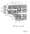
- FIG. 1 mainly shows a region of a gear chamber 10 of a power tool 1.
- the present embodiment illustrates a so-called screwdriver as an example of the power tool 1.
- a separating wall 5 is clamped between a main body housing 2 and a front housing 3 of this power tool 1.
- a space defined between the separating wall 5 and the front housing 3 serves as a gear chamber 10.
- a reduction gear train G is accommodated and outputs the rotative power of an electric motor 11 as a driving source after reduction in the rotational speed.
- An output shaft 12 of the electric motor 11 is rotatably supported by a ball bearing 20 mounted to the separating wall 5.
- the output shaft12 passes through the separating wall 5.
- a pinion gear part 12a is formed on a leading end of the output shaft 12 at a position inside the separating wall 5 (on the side of the gear chamber 10).
- a helical gear is used as this pinion gear part 12a.
- a cooling fan 13 is mounted to this output shaft 12 at a position on an outer side of the separating wall 5.
- the gear train G accommodated in the gear chamber 10 includes the aforementioned pinion gear part 12a and a drive gear 14 that engages with the pinion gear part 12a.
- a helical gear is used as this drive gear 14 to correspond to the pinion gear part 12a.
- the drive gear 14 is mounted to a drive shaft 15.
- the drive shaft 15 is supported by front and rear bearings 16 and 17 so as to be rotatable about its axis.
- the front bearing 16 is fitted into a supporting hole 4b formed in the spindle 4.
- the rear bearing 17 is fitted into the separating wall 5.
- the spindle 4 is rotatably supported by the front housing 3 via a bearing 19. Although not shown in the drawings, a leading end side of the spindle 4 extends into a front side of the front housing 3. A bit for tightening a screw is attached to the leading end of the spindle 4.
- a compressed spring 18 is interposed between the drive gear 14 and the spindle 4.
- the spindle 4 is biased forward by this compressed spring 18.
- Clutch teeth 4a are provided on the rear surface of the spindle 4.
- clutch teeth 14a are provided on the front surface of the drive gear 14.
- the spindle 4 Since the spindle 4 is pressed by the compressed spring 18, it moves forward (screw-tightening direction) as the screw proceeds in the tightening direction.
- the clutch teeth 4a are disengaged from the clutch teeth 14a and the transfer of the rotative power to the spindle 4 stops, which causes the drive gear 14 to run idle.
- the spindle 4 is moved forward and returned to the end position by the compressed spring 18. Further, when the electric motor 11 stops, the drive gear 13 also stops.
- Detailed explanations about the engaging clutch mechanism are omitted since this mechanism is well known.
- the compressed spring 18 and a rear part of the spindle 4 as well as the gear train G are accommodated within the gear chamber 10.
- grease is sealingly contained to primarily lubricate the gear train G.
- a helical gear is used as the pinion gear part 12a.
- the contained grease is apt to be raked toward the side of the bearing 20 by the pinion gear part 12a. Since the ball bearing 20 is constructed such that the steel balls are located between an inner race and an outer race, there is a narrow clearance between the inner race and the outer race. Thus, there is a possibility that grease raked by the pinion gear part 12a is leaked out of the gear chamber 10 through this narrow clearance.
- a sealing member 21 is attached to the ball bearing 20 on an inner side of the gear chamber 10 in order to prevent the grease from leaking through this ball bearing 20.
- This sealing member 21 has a substantially annular shape and is fixedly attached to the output shaft 12, so that the sealing member 21 rotates together with the output shaft 12. As shown in FIG.1 , the sealing member 21 always blocks the front side of the ball bearing 12 (the side of the gear chamber 10). The blocking by this sealing member 21 prevents the grease inside the gear chamber 10 from leaking outward through the ball bearing 12.
- a grease return part 21a is provided on the front surface of the sealing member 21 in order to more reliably prevent the grease inside the gear chamber 10 from leaking outward through the ball bearing 12. Thus, there is little grease leaked to the ball bearing 12.
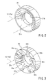
- FIG.2 shows the sealing member 21 independently.
- the sealing member 21, for example, is made of resin, and press-fitted on the output shaft 12. However, it may be made of metal.
- the grease return part 21a is formed as a mortar-like concave part as shown in the FIG.1 .
- a supporting hole 21b through which the output shaft 12 of the electric motor 11 is inserted is formed in the center of the sealing member 21.
- the grease return part 21a is curved in such a direction that its depth becomes deeper toward this supporting hole 21 b.
- helical gears are used as the pinion gear part 12a and the drive gear 14.
- the grease contained inside the gear chamber 10 is apt to be raked toward the ball bearing 20 as a result of the raking force of the helical gears produced when the pinion gear 12a rotates.
- the sealing member 21 is attached to the front side of the ball bearing 20 (inside the gear chamber 10). Since this sealing member 21 blocks the front side of the ball bearing 20 , the grease is prevented from moving to the ball bearing 20.
- the grease return part 21a of the sealing member 21 is curved in a mortar-shaped way, the grease raked toward the center of the sealing member 21 by the rotation of the pinion gear part 12a is blown off diagonally forward with respect to a radial direction as a result of the centrifugal force.
- a helical gear is used as the pinion gear part 12a to which the sealing member 21 is attached
- the present invention can be applied in the same way to the construction in which a normal spur gear is used as the pinion gear part 12a.
- the concave part curved in a mortar-shaped way is shown as the grease return part 21a
- the grease return part 21 may have any other configurations than this configuration.
- the curved concave part can be replaced with a tapered part.
- FIG.3 a structure having radial ribs 22cadded to a taper concave part can be adopted.
- a grease return part 22a of a sealing member 22 shown in FIG.3 is provided with a plurality of ribs 22calong the radial direction of the taper concave part.
- a supporting hole 22b through which the output shaft 12 is inserted is formed at the center of the sealing member 22.
- ball bearings are illustrated as bearings for rotatably supporting the output shaft 12 of the electric motor 11.
- the illustrated sealing member 21(22) can be applied to the other type of bearings having an inner race and an outer race, such as roller bearings and taper-rolling bearings, in order to achieve the same effect.
- the structure is shown in which the output shaft 12 of the electric motor 11 directly extends into the gear chamber 10.
- the illustrated sealing member 21(22) can be applied to obtain the same effect in a structure in which t the speed of the electric motor is reduced outside the gear chamber 10 by another reduction gear mechanism having a reduction shaft to which a reduction gear is attached.
- the reduction shaft extends into the gear chamber 10, thereby the output shaft of the electric motor indirectly extends into the gear chamber 10, so that the speed of the electric motor is reduced by the reduction gear mechanism and is further reduced by the reduction gear train G.
Landscapes
- Engineering & Computer Science (AREA)
- General Engineering & Computer Science (AREA)
- Mechanical Engineering (AREA)
- Sealing Of Bearings (AREA)
- General Details Of Gearings (AREA)
- Sealing Using Fluids, Sealing Without Contact, And Removal Of Oil (AREA)
- Sealing Devices (AREA)
- Gear Transmission (AREA)
Applications Claiming Priority (1)
| Application Number | Priority Date | Filing Date | Title |
|---|---|---|---|
| JP2008274340A JP5154364B2 (ja) | 2008-10-24 | 2008-10-24 | ギヤ室のシール構造 |
Publications (1)
| Publication Number | Publication Date |
|---|---|
| EP2180214A1 true EP2180214A1 (de) | 2010-04-28 |
Family
ID=41566065
Family Applications (1)
| Application Number | Title | Priority Date | Filing Date |
|---|---|---|---|
| EP09013417A Withdrawn EP2180214A1 (de) | 2008-10-24 | 2009-10-23 | Dichtungsvorrichtung für Getriebegehäuse |
Country Status (5)
| Country | Link |
|---|---|
| US (1) | US8186689B2 (de) |
| EP (1) | EP2180214A1 (de) |
| JP (1) | JP5154364B2 (de) |
| CN (1) | CN101725702B (de) |
| RU (1) | RU2501646C2 (de) |
Cited By (3)
| Publication number | Priority date | Publication date | Assignee | Title |
|---|---|---|---|---|
| EP3991919A1 (de) * | 2020-10-28 | 2022-05-04 | Hilti Aktiengesellschaft | Mobile werkzeugmaschine mit einem wasserhaltigen schmiermittel sowie verwendung der mobilen werkzeugmaschine |
| EP3991918A1 (de) * | 2020-10-28 | 2022-05-04 | Hilti Aktiengesellschaft | Dichtgeometrie für eine mobile werkzeugmaschine |
| EP4011561A1 (de) * | 2020-12-11 | 2022-06-15 | Hilti Aktiengesellschaft | Mobile werkzeugmaschine und verfahren |
Families Citing this family (7)
| Publication number | Priority date | Publication date | Assignee | Title |
|---|---|---|---|---|
| JP5787915B2 (ja) | 2013-02-13 | 2015-09-30 | オリエンタルモーター株式会社 | 歯車減速機付電動機における歯車減速機のグリース漏れ防止構造 |
| US11244349B2 (en) | 2015-12-29 | 2022-02-08 | Ebay Inc. | Methods and apparatus for detection of spam publication |
| CN105672888A (zh) * | 2016-01-08 | 2016-06-15 | 西南石油大学 | 一种牙轮钻头双向齿轮密封结构 |
| CN109854625A (zh) * | 2018-11-18 | 2019-06-07 | 中国电建集团铁路建设有限公司 | 一种盾构用自动调节主轴承密封脂注入系统 |
| KR102219737B1 (ko) * | 2019-02-21 | 2021-02-25 | 계양전기 주식회사 | 전동공구의 윤활구조 |
| US11885402B2 (en) | 2020-07-07 | 2024-01-30 | Transportation Ip Holdings, Llc | Gearcase assembly and method |
| DE102022212835A1 (de) | 2022-11-30 | 2024-06-06 | Robert Bosch Gesellschaft mit beschränkter Haftung | Handwerkzeugmaschine mit einem Distanzelement |
Citations (10)
| Publication number | Priority date | Publication date | Assignee | Title |
|---|---|---|---|---|
| DE3211715A1 (de) * | 1982-03-30 | 1983-10-13 | Siemens AG, 1000 Berlin und 8000 München | Druckgeschmierte waelzlageranordnung fuer die welle einer geschlossenen elektrischen maschine |
| FR2535815A1 (fr) * | 1982-11-05 | 1984-05-11 | Inventio Ag | Joint d'etancheite exempt de contact |
| US4632404A (en) * | 1984-07-09 | 1986-12-30 | Skf Gmbh | Seal for rolling bearing |
| JPS6232783U (de) | 1985-08-09 | 1987-02-26 | ||
| JPH0545293U (ja) | 1991-11-22 | 1993-06-18 | 株式会社小松製作所 | 減速機の潤滑機構 |
| DE19855879A1 (de) * | 1997-12-04 | 1999-06-10 | Sanford Acquisition Co Toledo | Schleuderring mit Zentrifugaldichtung |
| JPH11245179A (ja) | 1997-12-01 | 1999-09-14 | Black & Decker Inc | パワーツール |
| EP1239173A2 (de) * | 2001-03-05 | 2002-09-11 | Minebea Co., Ltd. | Dichtungssystem für ein Wälzlager |
| US20020131658A1 (en) * | 2001-03-16 | 2002-09-19 | Andreas Stihl Ag & Co. | Anti-friction bearing |
| US20080075401A1 (en) * | 2006-09-20 | 2008-03-27 | Stefan Dorner | Shaft bearing seal |
Family Cites Families (15)
| Publication number | Priority date | Publication date | Assignee | Title |
|---|---|---|---|---|
| US2005526A (en) * | 1932-09-27 | 1935-06-18 | Hauser & Co G M B H | Seal for axle boxes |
| US2688502A (en) * | 1950-04-21 | 1954-09-07 | Gen Motors Corp | Demountable seal |
| US3292847A (en) * | 1964-11-03 | 1966-12-20 | Dresser Ind | Lubricant sealing means for rotary positive displacement pump |
| JPS6232783A (ja) | 1985-08-05 | 1987-02-12 | Mitsubishi Electric Corp | 磁気録画再生装置 |
| US5035155A (en) * | 1989-09-01 | 1991-07-30 | Robledo Ismael L | Device for preventing contamination of transmission fluid |
| GB8925421D0 (en) * | 1989-11-10 | 1989-12-28 | Boc Group Plc | Shaft sealing arrangements |
| US5201532A (en) * | 1991-12-12 | 1993-04-13 | Mark Controls Corporation | Flexible non-planar graphite sealing ring |
| JP4650913B2 (ja) * | 2000-04-27 | 2011-03-16 | 株式会社ハーモニック・ドライブ・システムズ | 中空型波動歯車装置の潤滑剤漏れ防止機構 |
| US6550350B2 (en) * | 2001-06-13 | 2003-04-22 | Trw Inc. | Boot for a rack and pinion steering gear assembly |
| US6629816B2 (en) * | 2001-08-16 | 2003-10-07 | Honeywell International Inc. | Non-contacting clearance seal for high misalignment applications |
| US7296801B2 (en) * | 2004-02-24 | 2007-11-20 | Mao-Lin Chen | Anti-leakage device for lubrication oil in a fan |
| RU2311282C2 (ru) * | 2004-11-05 | 2007-11-27 | Хитачи Коки Ко., Лтд. | Приводной инструмент с устройством для предотвращения утечки смазочного материала (варианты) |
| JP4995453B2 (ja) * | 2005-11-14 | 2012-08-08 | 株式会社小松製作所 | 建設機械の回転輪機構及び建設機械の駆動輪機構 |
| JP2007263201A (ja) * | 2006-03-28 | 2007-10-11 | Nidec-Shimpo Corp | 歯車装置における潤滑剤のシール構造 |
| US20080196523A1 (en) * | 2007-02-16 | 2008-08-21 | Chia-Min Liu | Dustproof Device for a Ball Screw |
-
2008
- 2008-10-24 JP JP2008274340A patent/JP5154364B2/ja active Active
-
2009
- 2009-07-30 CN CN200910157500.5A patent/CN101725702B/zh active Active
- 2009-10-21 US US12/588,612 patent/US8186689B2/en active Active
- 2009-10-23 EP EP09013417A patent/EP2180214A1/de not_active Withdrawn
- 2009-10-23 RU RU2009139263/02A patent/RU2501646C2/ru active
Patent Citations (10)
| Publication number | Priority date | Publication date | Assignee | Title |
|---|---|---|---|---|
| DE3211715A1 (de) * | 1982-03-30 | 1983-10-13 | Siemens AG, 1000 Berlin und 8000 München | Druckgeschmierte waelzlageranordnung fuer die welle einer geschlossenen elektrischen maschine |
| FR2535815A1 (fr) * | 1982-11-05 | 1984-05-11 | Inventio Ag | Joint d'etancheite exempt de contact |
| US4632404A (en) * | 1984-07-09 | 1986-12-30 | Skf Gmbh | Seal for rolling bearing |
| JPS6232783U (de) | 1985-08-09 | 1987-02-26 | ||
| JPH0545293U (ja) | 1991-11-22 | 1993-06-18 | 株式会社小松製作所 | 減速機の潤滑機構 |
| JPH11245179A (ja) | 1997-12-01 | 1999-09-14 | Black & Decker Inc | パワーツール |
| DE19855879A1 (de) * | 1997-12-04 | 1999-06-10 | Sanford Acquisition Co Toledo | Schleuderring mit Zentrifugaldichtung |
| EP1239173A2 (de) * | 2001-03-05 | 2002-09-11 | Minebea Co., Ltd. | Dichtungssystem für ein Wälzlager |
| US20020131658A1 (en) * | 2001-03-16 | 2002-09-19 | Andreas Stihl Ag & Co. | Anti-friction bearing |
| US20080075401A1 (en) * | 2006-09-20 | 2008-03-27 | Stefan Dorner | Shaft bearing seal |
Cited By (6)
| Publication number | Priority date | Publication date | Assignee | Title |
|---|---|---|---|---|
| EP3991919A1 (de) * | 2020-10-28 | 2022-05-04 | Hilti Aktiengesellschaft | Mobile werkzeugmaschine mit einem wasserhaltigen schmiermittel sowie verwendung der mobilen werkzeugmaschine |
| EP3991918A1 (de) * | 2020-10-28 | 2022-05-04 | Hilti Aktiengesellschaft | Dichtgeometrie für eine mobile werkzeugmaschine |
| WO2022089945A1 (de) * | 2020-10-28 | 2022-05-05 | Hilti Aktiengesellschaft | Dichtgeometrie für eine mobile werkzeugmaschine |
| WO2022089946A1 (de) * | 2020-10-28 | 2022-05-05 | Hilti Aktiengesellschaft | Mobile werkzeugmaschine mit einem wasserhaltigen schmiermittel sowie verwendung der mobilen werkzeugmaschine |
| EP4011561A1 (de) * | 2020-12-11 | 2022-06-15 | Hilti Aktiengesellschaft | Mobile werkzeugmaschine und verfahren |
| WO2022122413A1 (de) * | 2020-12-11 | 2022-06-16 | Hilti Aktiengesellschaft | Mobile werkzeugmaschine und verfahren |
Also Published As
| Publication number | Publication date |
|---|---|
| CN101725702A (zh) | 2010-06-09 |
| RU2501646C2 (ru) | 2013-12-20 |
| JP2010101444A (ja) | 2010-05-06 |
| RU2009139263A (ru) | 2011-04-27 |
| US8186689B2 (en) | 2012-05-29 |
| JP5154364B2 (ja) | 2013-02-27 |
| US20100102515A1 (en) | 2010-04-29 |
| CN101725702B (zh) | 2015-04-08 |
Similar Documents
| Publication | Publication Date | Title |
|---|---|---|
| US8186689B2 (en) | Sealing device for gear chamber | |
| EP2735463A1 (de) | Planetengetriebevorrichtung | |
| JP6107920B2 (ja) | 直動アクチュエータの製造方法 | |
| US8857536B2 (en) | Hand-held power tool | |
| CN112368164A (zh) | 具有驻车锁的变速器装置和具有变速器装置的电驱动装置 | |
| US20100224033A1 (en) | Handheld power tool | |
| US20100192389A1 (en) | Electric cutting tool | |
| JP4026152B2 (ja) | 歯車駆動装置 | |
| EP2784358A1 (de) | Stufenlos einstellbares Keilriemengetriebe | |
| US12017313B2 (en) | Impact tool | |
| JP2007154998A (ja) | 歯車減速機付電動機のグリース漏れ防止構造 | |
| JP2013164139A (ja) | インホイールモータ駆動装置 | |
| US7568531B2 (en) | Gear transmission device for power tool | |
| US6769185B2 (en) | Gearbox head | |
| EP1582777A3 (de) | Ölpumpenrad und Welle für Leistungsgetriebe | |
| US7168505B2 (en) | Rotary tool | |
| JP2004174656A (ja) | インパクト工具 | |
| JP4610242B2 (ja) | 歯車と回転軸との接合構造、及びそれを用いた遊星歯車減速機 | |
| JP2016161068A (ja) | 無段変速機及びアクチュエータ | |
| JP4157488B2 (ja) | 機関始動装置 | |
| CN210397642U (zh) | 电器装置变速机构 | |
| CN210440533U (zh) | 电器装置变速机构 | |
| JPH10127002A (ja) | 歯車減速装置付き電動機の軸受装置 | |
| JPH11301496A (ja) | 動力舵取装置 | |
| WO2017135047A1 (ja) | ベルト式無段変速機 |
Legal Events
| Date | Code | Title | Description |
|---|---|---|---|
| PUAI | Public reference made under article 153(3) epc to a published international application that has entered the european phase |
Free format text: ORIGINAL CODE: 0009012 |
|
| AK | Designated contracting states |
Kind code of ref document: A1 Designated state(s): AT BE BG CH CY CZ DE DK EE ES FI FR GB GR HR HU IE IS IT LI LT LU LV MC MK MT NL NO PL PT RO SE SI SK SM TR |
|
| AX | Request for extension of the european patent |
Extension state: AL BA RS |
|
| 17P | Request for examination filed |
Effective date: 20101001 |
|
| 17Q | First examination report despatched |
Effective date: 20110607 |
|
| GRAP | Despatch of communication of intention to grant a patent |
Free format text: ORIGINAL CODE: EPIDOSNIGR1 |
|
| INTG | Intention to grant announced |
Effective date: 20140410 |
|
| STAA | Information on the status of an ep patent application or granted ep patent |
Free format text: STATUS: THE APPLICATION IS DEEMED TO BE WITHDRAWN |
|
| 18D | Application deemed to be withdrawn |
Effective date: 20140821 |