EP2180214A1 - Sealing device for gear chamber - Google Patents
Sealing device for gear chamber Download PDFInfo
- Publication number
- EP2180214A1 EP2180214A1 EP09013417A EP09013417A EP2180214A1 EP 2180214 A1 EP2180214 A1 EP 2180214A1 EP 09013417 A EP09013417 A EP 09013417A EP 09013417 A EP09013417 A EP 09013417A EP 2180214 A1 EP2180214 A1 EP 2180214A1
- Authority
- EP
- European Patent Office
- Prior art keywords
- sealing device
- grease
- rotary shaft
- bearing
- gear chamber
- Prior art date
- Legal status (The legal status is an assumption and is not a legal conclusion. Google has not performed a legal analysis and makes no representation as to the accuracy of the status listed.)
- Withdrawn
Links
Images
Classifications
-
- B—PERFORMING OPERATIONS; TRANSPORTING
- B25—HAND TOOLS; PORTABLE POWER-DRIVEN TOOLS; MANIPULATORS
- B25F—COMBINATION OR MULTI-PURPOSE TOOLS NOT OTHERWISE PROVIDED FOR; DETAILS OR COMPONENTS OF PORTABLE POWER-DRIVEN TOOLS NOT PARTICULARLY RELATED TO THE OPERATIONS PERFORMED AND NOT OTHERWISE PROVIDED FOR
- B25F5/00—Details or components of portable power-driven tools not particularly related to the operations performed and not otherwise provided for
- B25F5/02—Construction of casings, bodies or handles
-
- F—MECHANICAL ENGINEERING; LIGHTING; HEATING; WEAPONS; BLASTING
- F16—ENGINEERING ELEMENTS AND UNITS; GENERAL MEASURES FOR PRODUCING AND MAINTAINING EFFECTIVE FUNCTIONING OF MACHINES OR INSTALLATIONS; THERMAL INSULATION IN GENERAL
- F16C—SHAFTS; FLEXIBLE SHAFTS; ELEMENTS OR CRANKSHAFT MECHANISMS; ROTARY BODIES OTHER THAN GEARING ELEMENTS; BEARINGS
- F16C33/00—Parts of bearings; Special methods for making bearings or parts thereof
- F16C33/72—Sealings
- F16C33/76—Sealings of ball or roller bearings
-
- F—MECHANICAL ENGINEERING; LIGHTING; HEATING; WEAPONS; BLASTING
- F16—ENGINEERING ELEMENTS AND UNITS; GENERAL MEASURES FOR PRODUCING AND MAINTAINING EFFECTIVE FUNCTIONING OF MACHINES OR INSTALLATIONS; THERMAL INSULATION IN GENERAL
- F16H—GEARING
- F16H57/00—General details of gearing
- F16H57/04—Features relating to lubrication or cooling or heating
- F16H57/042—Guidance of lubricant
- F16H57/0427—Guidance of lubricant on rotary parts, e.g. using baffles for collecting lubricant by centrifugal force
-
- F—MECHANICAL ENGINEERING; LIGHTING; HEATING; WEAPONS; BLASTING
- F16—ENGINEERING ELEMENTS AND UNITS; GENERAL MEASURES FOR PRODUCING AND MAINTAINING EFFECTIVE FUNCTIONING OF MACHINES OR INSTALLATIONS; THERMAL INSULATION IN GENERAL
- F16H—GEARING
- F16H57/00—General details of gearing
- F16H57/04—Features relating to lubrication or cooling or heating
- F16H57/048—Type of gearings to be lubricated, cooled or heated
- F16H57/0493—Gearings with spur or bevel gears
Definitions
- the present invention relates to a sealing device for a gear chamber of a power tool such as an electric screwdriver, which gear chamber accommodates a gear train that can reduce a rotational speed of an electric motor and output a rotative power.
- a gear chamber for accommodating a reduction gear train that can reduce a rotational speed of an electric motor as a driving source and output a rotative power.
- Grease lubricating oil
- the gear chamber for example, an output shaft of the electric motor as an input side component and a spindle as an output side component are rotatably supported respectively, and the reduction gear train is located between them.
- Support sections for the spindle and the output shaft of separating walls defining the gear chamber include bearings for rotatably supporting these parts , and in addition to this, sealing members are attached for preventing grease from leaking out of the bearings.
- Japanese Laid-Open Patent Publication No. 11-245179 describes a technology to provide a means for compulsively circulating and scattering grease contained in at least one of an input shaft and an output shaft each protruding into the gear chamber.
- Japanese Laid-Open Utility Model Publication No. 11-245179 describes a technology to provide a means for compulsively circulating and scattering grease contained in at least one of an input shaft and an output shaft each protruding into the gear chamber.
- 5-45293 describes a technology to efficiently lubricate by a little amount of grease by providing a rib or a concave part in a part of a gear of a gear train to splash the grease upward as a result of centrifugal force.
- Japanese Laid-Open Utility Model Publication No. 62-32783 describes a technology to prevent grease from leaking out of bearings that rotatably support a motor shaft by attaching a helical coil on the motor shaft to cause rotation of the helical coil together with the motor shaft.
- the helical direction of the helical coil is opposite to the rotational direction of a pinion.
- One aspect according to the present invention includes a sealing device for sealing between a gear chamber and an electric motor.
- the gear chamber accommodates a reduction gear train and contains grease for lubricating the reduction gear train, and the reduction gear train reduces rotation of an electric motor.
- the sealing device further includes a separating wall separating the gear chamber from the electric motor and supporting a rotary shaft via a bearing. The rotation of the electric motor is transmitted to the reduction gear via the rotary shaft.
- the sealing device further includes a sealing member attached to the rotary shaft so as to be able to rotate together with the rotary shaft, and a grease return part provided on the sealing member on the side of the gear chamber so that the grease can be blown off in a direction away from the bearing as a result of a centrifugal force produced by the rotation of the rotary shaft.
- the sealing member rotating together with the output shaft causes the grease attached to the grease return part of the sealing member (the gear chamber side) to scatter toward the central side of the gear chamber (direction away from the bearing) as a result of a centrifugal force.
- the grease flowing toward the bearing and received by the grease return part is returned back to the central side of the gear chamber as a result of a centrifugal force. Therefore, the grease that will leak out of the bearings outside off the gear chamber can be reduced.
- the grease return part may have a concave surface having a mortar-like configuration. Simply providing the mortar shaped concave surface to the grease return part can prevent the grease from leaking out of the gear chamber.
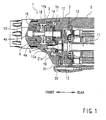
- FIG. 1 mainly shows a region of a gear chamber 10 of a power tool 1.
- the present embodiment illustrates a so-called screwdriver as an example of the power tool 1.
- a separating wall 5 is clamped between a main body housing 2 and a front housing 3 of this power tool 1.
- a space defined between the separating wall 5 and the front housing 3 serves as a gear chamber 10.
- a reduction gear train G is accommodated and outputs the rotative power of an electric motor 11 as a driving source after reduction in the rotational speed.
- An output shaft 12 of the electric motor 11 is rotatably supported by a ball bearing 20 mounted to the separating wall 5.
- the output shaft12 passes through the separating wall 5.
- a pinion gear part 12a is formed on a leading end of the output shaft 12 at a position inside the separating wall 5 (on the side of the gear chamber 10).
- a helical gear is used as this pinion gear part 12a.
- a cooling fan 13 is mounted to this output shaft 12 at a position on an outer side of the separating wall 5.
- the gear train G accommodated in the gear chamber 10 includes the aforementioned pinion gear part 12a and a drive gear 14 that engages with the pinion gear part 12a.
- a helical gear is used as this drive gear 14 to correspond to the pinion gear part 12a.
- the drive gear 14 is mounted to a drive shaft 15.
- the drive shaft 15 is supported by front and rear bearings 16 and 17 so as to be rotatable about its axis.
- the front bearing 16 is fitted into a supporting hole 4b formed in the spindle 4.
- the rear bearing 17 is fitted into the separating wall 5.
- the spindle 4 is rotatably supported by the front housing 3 via a bearing 19. Although not shown in the drawings, a leading end side of the spindle 4 extends into a front side of the front housing 3. A bit for tightening a screw is attached to the leading end of the spindle 4.
- a compressed spring 18 is interposed between the drive gear 14 and the spindle 4.
- the spindle 4 is biased forward by this compressed spring 18.
- Clutch teeth 4a are provided on the rear surface of the spindle 4.
- clutch teeth 14a are provided on the front surface of the drive gear 14.
- the spindle 4 Since the spindle 4 is pressed by the compressed spring 18, it moves forward (screw-tightening direction) as the screw proceeds in the tightening direction.
- the clutch teeth 4a are disengaged from the clutch teeth 14a and the transfer of the rotative power to the spindle 4 stops, which causes the drive gear 14 to run idle.
- the spindle 4 is moved forward and returned to the end position by the compressed spring 18. Further, when the electric motor 11 stops, the drive gear 13 also stops.
- Detailed explanations about the engaging clutch mechanism are omitted since this mechanism is well known.
- the compressed spring 18 and a rear part of the spindle 4 as well as the gear train G are accommodated within the gear chamber 10.
- grease is sealingly contained to primarily lubricate the gear train G.
- a helical gear is used as the pinion gear part 12a.
- the contained grease is apt to be raked toward the side of the bearing 20 by the pinion gear part 12a. Since the ball bearing 20 is constructed such that the steel balls are located between an inner race and an outer race, there is a narrow clearance between the inner race and the outer race. Thus, there is a possibility that grease raked by the pinion gear part 12a is leaked out of the gear chamber 10 through this narrow clearance.
- a sealing member 21 is attached to the ball bearing 20 on an inner side of the gear chamber 10 in order to prevent the grease from leaking through this ball bearing 20.
- This sealing member 21 has a substantially annular shape and is fixedly attached to the output shaft 12, so that the sealing member 21 rotates together with the output shaft 12. As shown in FIG.1 , the sealing member 21 always blocks the front side of the ball bearing 12 (the side of the gear chamber 10). The blocking by this sealing member 21 prevents the grease inside the gear chamber 10 from leaking outward through the ball bearing 12.
- a grease return part 21a is provided on the front surface of the sealing member 21 in order to more reliably prevent the grease inside the gear chamber 10 from leaking outward through the ball bearing 12. Thus, there is little grease leaked to the ball bearing 12.
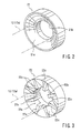
- FIG.2 shows the sealing member 21 independently.
- the sealing member 21, for example, is made of resin, and press-fitted on the output shaft 12. However, it may be made of metal.
- the grease return part 21a is formed as a mortar-like concave part as shown in the FIG.1 .
- a supporting hole 21b through which the output shaft 12 of the electric motor 11 is inserted is formed in the center of the sealing member 21.
- the grease return part 21a is curved in such a direction that its depth becomes deeper toward this supporting hole 21 b.
- helical gears are used as the pinion gear part 12a and the drive gear 14.
- the grease contained inside the gear chamber 10 is apt to be raked toward the ball bearing 20 as a result of the raking force of the helical gears produced when the pinion gear 12a rotates.
- the sealing member 21 is attached to the front side of the ball bearing 20 (inside the gear chamber 10). Since this sealing member 21 blocks the front side of the ball bearing 20 , the grease is prevented from moving to the ball bearing 20.
- the grease return part 21a of the sealing member 21 is curved in a mortar-shaped way, the grease raked toward the center of the sealing member 21 by the rotation of the pinion gear part 12a is blown off diagonally forward with respect to a radial direction as a result of the centrifugal force.
- a helical gear is used as the pinion gear part 12a to which the sealing member 21 is attached
- the present invention can be applied in the same way to the construction in which a normal spur gear is used as the pinion gear part 12a.
- the concave part curved in a mortar-shaped way is shown as the grease return part 21a
- the grease return part 21 may have any other configurations than this configuration.
- the curved concave part can be replaced with a tapered part.
- FIG.3 a structure having radial ribs 22cadded to a taper concave part can be adopted.
- a grease return part 22a of a sealing member 22 shown in FIG.3 is provided with a plurality of ribs 22calong the radial direction of the taper concave part.
- a supporting hole 22b through which the output shaft 12 is inserted is formed at the center of the sealing member 22.
- ball bearings are illustrated as bearings for rotatably supporting the output shaft 12 of the electric motor 11.
- the illustrated sealing member 21(22) can be applied to the other type of bearings having an inner race and an outer race, such as roller bearings and taper-rolling bearings, in order to achieve the same effect.
- the structure is shown in which the output shaft 12 of the electric motor 11 directly extends into the gear chamber 10.
- the illustrated sealing member 21(22) can be applied to obtain the same effect in a structure in which t the speed of the electric motor is reduced outside the gear chamber 10 by another reduction gear mechanism having a reduction shaft to which a reduction gear is attached.
- the reduction shaft extends into the gear chamber 10, thereby the output shaft of the electric motor indirectly extends into the gear chamber 10, so that the speed of the electric motor is reduced by the reduction gear mechanism and is further reduced by the reduction gear train G.
Landscapes
- Engineering & Computer Science (AREA)
- General Engineering & Computer Science (AREA)
- Mechanical Engineering (AREA)
- Sealing Of Bearings (AREA)
- General Details Of Gearings (AREA)
- Sealing Using Fluids, Sealing Without Contact, And Removal Of Oil (AREA)
- Sealing Devices (AREA)
- Gear Transmission (AREA)
Abstract
Description
- This application claims priority to Japanese patent application serial number
2008-274340 - The present invention relates to a sealing device for a gear chamber of a power tool such as an electric screwdriver, which gear chamber accommodates a gear train that can reduce a rotational speed of an electric motor and output a rotative power.
- Inside a main body of this kind of power tools, a gear chamber is defined for accommodating a reduction gear train that can reduce a rotational speed of an electric motor as a driving source and output a rotative power. Grease (lubricating oil) is sealingly contained in the gear chamber to lubricate the gear train accommodated in this gear chamber. In the gear chamber, for example, an output shaft of the electric motor as an input side component and a spindle as an output side component are rotatably supported respectively, and the reduction gear train is located between them. Support sections for the spindle and the output shaft of separating walls defining the gear chamber include bearings for rotatably supporting these parts , and in addition to this, sealing members are attached for preventing grease from leaking out of the bearings.
- Known technologies relating to a gear chamber and a sealing structure for sealing the gear chamber are disclosed in Japanese Laid-Open Patent Publication No.
11-245179 5-45293 62-32783 11-245179 5-45293 62-32783 - However, the technologies disclosed in Japanese Laid-Open Patent Publication Nos.
11-245179 5-45293 62-32783 - Therefore, there is a need in the art to provide a sealing device that can reliably prevent the grease from leaking out of the gear chamber in a compact and simple structure without increasing in size of the power tool.
- One aspect according to the present invention includes a sealing device for sealing between a gear chamber and an electric motor. The gear chamber accommodates a reduction gear train and contains grease for lubricating the reduction gear train, and the reduction gear train reduces rotation of an electric motor. The sealing device further includes a separating wall separating the gear chamber from the electric motor and supporting a rotary shaft via a bearing. The rotation of the electric motor is transmitted to the reduction gear via the rotary shaft. The sealing device further includes a sealing member attached to the rotary shaft so as to be able to rotate together with the rotary shaft, and a grease return part provided on the sealing member on the side of the gear chamber so that the grease can be blown off in a direction away from the bearing as a result of a centrifugal force produced by the rotation of the rotary shaft.
- Therefore, the sealing member rotating together with the output shaft causes the grease attached to the grease return part of the sealing member (the gear chamber side) to scatter toward the central side of the gear chamber (direction away from the bearing) as a result of a centrifugal force. Thus, the grease flowing toward the bearing and received by the grease return part is returned back to the central side of the gear chamber as a result of a centrifugal force. Therefore, the grease that will leak out of the bearings outside off the gear chamber can be reduced.
- Hence, it is possible to reliably prevent the grease from leaking out of the gear chamber by a simple structure without accompanying increase in size of the tool grow in size in a length wise direction, because it is only necessary to attach an annular sealing member to the output shaft instead of a known helical coil.
- The grease return part may have a concave surface having a mortar-like configuration. Simply providing the mortar shaped concave surface to the grease return part can prevent the grease from leaking out of the gear chamber.
- Additional objects, features, and advantages, of the present invention will be readily understood after reading the following detailed description together with the claims and the accompanying drawings, in which:
-
FIG.1 is a side view showing the internal structure of a power tool incorporating a sealing device according to an embodiment of the present invention; -
FIG.2 is a perspective view of a sealing member of the sealing device; and -
FIG.3 is a perspective view of a sealing member according to another embodiment of the present invention. - Each of the additional features and teachings disclosed above and below may be utilized separately or in conjunction with other features and teachings to provide improved sealing devices. Representative examples of the present invention, which examples utilize many of these additional features and teachings both separately and in conjunction with one another, will now be described in detail with reference to the attached drawings. This detailed description is merely intended to teach a person of skill in the art further details for practicing preferred aspects of the present teachings and is not intended to limit the scope of the invention. Only the claims define the scope of the claimed invention. Therefore, combinations of features and steps disclosed in the following detailed description may not be necessary to practice the invention in the broadest sense, and are instead taught merely to particularly describe representative examples of the invention. Moreover, various features of the representative examples and the dependent claims may be combined in ways that are not specifically enumerated in order to provide additional useful embodiments of the present teachings.
- Next, an embodiment of the present invention will be described with reference to
FIGS. 1 to 3 .FIG. 1 mainly shows a region of agear chamber 10 of apower tool 1. The present embodiment illustrates a so-called screwdriver as an example of thepower tool 1. A separatingwall 5 is clamped between amain body housing 2 and a front housing 3 of thispower tool 1. A space defined between the separatingwall 5 and the front housing 3 serves as agear chamber 10. - In this
gear chamber 10, a reduction gear train G is accommodated and outputs the rotative power of anelectric motor 11 as a driving source after reduction in the rotational speed. Anoutput shaft 12 of theelectric motor 11 is rotatably supported by a ball bearing 20 mounted to the separatingwall 5. The output shaft12 passes through the separatingwall 5. Apinion gear part 12a is formed on a leading end of theoutput shaft 12 at a position inside the separating wall 5 (on the side of the gear chamber 10). In this present embodiment, a helical gear is used as thispinion gear part 12a. Acooling fan 13 is mounted to thisoutput shaft 12 at a position on an outer side of the separatingwall 5. - The gear train G accommodated in the
gear chamber 10 includes the aforementionedpinion gear part 12a and adrive gear 14 that engages with thepinion gear part 12a. A helical gear is used as thisdrive gear 14 to correspond to thepinion gear part 12a. - The
drive gear 14 is mounted to adrive shaft 15. Thedrive shaft 15 is supported by front andrear bearings hole 4b formed in thespindle 4. Therear bearing 17 is fitted into the separatingwall 5. - The
spindle 4 is rotatably supported by the front housing 3 via abearing 19. Although not shown in the drawings, a leading end side of thespindle 4 extends into a front side of the front housing 3. A bit for tightening a screw is attached to the leading end of thespindle 4. - A compressed
spring 18 is interposed between thedrive gear 14 and thespindle 4. Thespindle 4 is biased forward by this compressedspring 18.Clutch teeth 4a are provided on the rear surface of thespindle 4. Meanwhile,clutch teeth 14a are provided on the front surface of thedrive gear 14. By setting a screw to the screw-tightening bit attached to the leading end of thespindle 4 and pressing thepower tool 1 in the screw-tightening direction in a condition where the set screw is positioned at a position intended for tightening the screw, theclutch teeth 4a are engaged with theclutch teeth 14a on the side of thedrive gear 14 as a result of the retracting movement of thespindle 4 against thecompressed spring 18, so that the rotative power of theelectric motor 11 is transmitted to thespindle 4. - Since the
spindle 4 is pressed by the compressedspring 18, it moves forward (screw-tightening direction) as the screw proceeds in the tightening direction. When thespindle 4 has moved forward with a fixed stroke and the screw has been tightened completely, theclutch teeth 4a are disengaged from theclutch teeth 14a and the transfer of the rotative power to thespindle 4 stops, which causes thedrive gear 14 to run idle. After that, when the pressing operation of thepower tool 1 is released, thespindle 4 is moved forward and returned to the end position by thecompressed spring 18. Further, when theelectric motor 11 stops, thedrive gear 13 also stops. Detailed explanations about the engaging clutch mechanism are omitted since this mechanism is well known. - The
compressed spring 18 and a rear part of thespindle 4 as well as the gear train G are accommodated within thegear chamber 10. Inside thisgear chamber 10, grease is sealingly contained to primarily lubricate the gear train G. As described above, a helical gear is used as thepinion gear part 12a. For this reason, depending on factors including a rotational direction of thepinion gear part 12a, a helical angle and a helical direction of the pinion gear part or thehelical gear 12a, etc., the contained grease is apt to be raked toward the side of thebearing 20 by thepinion gear part 12a. Since theball bearing 20 is constructed such that the steel balls are located between an inner race and an outer race, there is a narrow clearance between the inner race and the outer race. Thus, there is a possibility that grease raked by thepinion gear part 12a is leaked out of thegear chamber 10 through this narrow clearance. - According to this embodiment, a sealing
member 21 is attached to theball bearing 20 on an inner side of thegear chamber 10 in order to prevent the grease from leaking through thisball bearing 20. This sealingmember 21 has a substantially annular shape and is fixedly attached to theoutput shaft 12, so that the sealingmember 21 rotates together with theoutput shaft 12. As shown inFIG.1 , the sealingmember 21 always blocks the front side of the ball bearing 12 (the side of the gear chamber 10). The blocking by this sealingmember 21 prevents the grease inside thegear chamber 10 from leaking outward through theball bearing 12. - In addition, a
grease return part 21a is provided on the front surface of the sealingmember 21 in order to more reliably prevent the grease inside thegear chamber 10 from leaking outward through theball bearing 12. Thus, there is little grease leaked to theball bearing 12. -
FIG.2 shows the sealingmember 21 independently. The sealingmember 21, for example, is made of resin, and press-fitted on theoutput shaft 12. However, it may be made of metal. In the present embodiment, thegrease return part 21a is formed as a mortar-like concave part as shown in theFIG.1 . A supportinghole 21b through which theoutput shaft 12 of theelectric motor 11 is inserted is formed in the center of the sealingmember 21. Thegrease return part 21a is curved in such a direction that its depth becomes deeper toward this supportinghole 21 b. When theelectric motor 11 starts to run, this sealingmember 21 rotates together with theoutput shaft 12. For this reason, a centrifugal force acts on the grease adhered to thegrease return part 21a when theelectric motor 11 starts to run and the sealingmember 21 rotates. As the centrifugal force acts on the grease adhered to thegrease return part 21 a, the grease moves toward the outer circumference while whirling along and within thegrease return part 21a, and eventually the grease is blown off forward. - In this way, the grease raked toward the
ball bearing 20 is received in thegrease return part 21a of the sealingmember 21, and eventually the grease inside thegear chamber 10 is prevented from leaking outward (inside the main body housing 2) through theball bearing 20. Further, since the grease is received in thegrease return part 21 a curved in a mortar-shaped way, it returns diagonally forward (in a direction away from theball bearing 20 and toward the center of the gear chamber 10) as a result of the centrifugal force, not merely radially. For this reason, it is further ensured that the grease is prevented from leaking through theball bearing 20. - According to the sealing device constructed as described above, helical gears are used as the
pinion gear part 12a and thedrive gear 14. Depending on the rotative direction of these helical gears, helical direction or helical angle of the helical gears, the grease contained inside thegear chamber 10 is apt to be raked toward theball bearing 20 as a result of the raking force of the helical gears produced when thepinion gear 12a rotates. In view of this, according to this embodiment, the sealingmember 21 is attached to the front side of the ball bearing 20 (inside the gear chamber 10). Since this sealingmember 21 blocks the front side of theball bearing 20 , the grease is prevented from moving to theball bearing 20. - Further, since the
grease return part 21a of the sealingmember 21 is curved in a mortar-shaped way, the grease raked toward the center of the sealingmember 21 by the rotation of thepinion gear part 12a is blown off diagonally forward with respect to a radial direction as a result of the centrifugal force. Thus, it is possible to prevent the grease from being raked toward thebearing 20 and from leaking outward, and consequently, it is possible to improve the sealing of thegear chamber 10. - In addition, the above effect can be obtained with a simple and compact structure in which the annular sealing
member 21 having an outer diameter smaller than an outer diameter of theball bearing 20 is attached to theoutput shaft 12a. - Various modifications can be made to the embodiment explained above. For example, although an electric screwdriver is illustrated as an example of the
power tool 1 in the above embodiment, the present invention can be applied to any other power tools or air tools having a gear chamber in which lubricating oil is contained. - Further, although, in the illustrated construction, a helical gear is used as the
pinion gear part 12a to which the sealingmember 21 is attached, the present invention can be applied in the same way to the construction in which a normal spur gear is used as thepinion gear part 12a. - Further, although the concave part curved in a mortar-shaped way is shown as the
grease return part 21a, thegrease return part 21 may have any other configurations than this configuration. For example, the curved concave part can be replaced with a tapered part. Further, as shown inFIG.3 , a structure having radial ribs 22cadded to a taper concave part can be adopted. Agrease return part 22a of a sealingmember 22 shown inFIG.3 is provided with a plurality of ribs 22calong the radial direction of the taper concave part. A supportinghole 22b through which theoutput shaft 12 is inserted is formed at the center of the sealingmember 22. - By the
grease return part 22a of this sealingmember 22, a centrifugal force also acts on the grease received in thegrease return part 22a that rotates together with theoutput shaft 12. For this reason, the grease raked by thepinion gear part 12a toward the central side of thegrease return part 22a is returned to the central side of thegear chamber 10 as a result of the centrifugal force. In case of thisgrease return part 22a, the grease moved to the central side of thegrease return part 22a is forced to be raked by eachrib 22c and is blown off outward in a radial direction as a result of the centrifugal force, and eventually the sealing performance of thegear chamber 10 can be further improved. - In the above embodiments, ball bearings are illustrated as bearings for rotatably supporting the
output shaft 12 of theelectric motor 11. However, the illustrated sealing member 21(22) can be applied to the other type of bearings having an inner race and an outer race, such as roller bearings and taper-rolling bearings, in order to achieve the same effect. - Further, in the above embodiments, the structure is shown in which the
output shaft 12 of theelectric motor 11 directly extends into thegear chamber 10. However, the illustrated sealing member 21(22) can be applied to obtain the same effect in a structure in which t the speed of the electric motor is reduced outside thegear chamber 10 by another reduction gear mechanism having a reduction shaft to which a reduction gear is attached. The reduction shaft extends into thegear chamber 10, thereby the output shaft of the electric motor indirectly extends into thegear chamber 10, so that the speed of the electric motor is reduced by the reduction gear mechanism and is further reduced by the reduction gear train G.
Claims (15)
- A sealing device for preventing grease from leaking out of a gear chamber (10), the gear chamber (10) accommodating therein a reduction gear train (G) and containing therein the grease for lubricating the reduction gear train (G), the reduction gear train (G) reducing rotation of an electric motor (11), the sealing device comprising:a separating wall (5) separating said gear chamber (10) from the electric motor (11) and supporting a rotary shaft (12) via a bearing (20), the rotation of the electric motor (11) being transmitted to the reduction gear train (G) via the rotary shaft (12);a sealing member (21; 22) attached to the rotary shaft (12) so as to be able to rotate together with the rotary shaft (12); anda grease return part (21a; 22a) provided on the sealing member (21; 22) on the side of the gear chamber (10), so that the grease can be blown off in a direction away from the bearing (20) as a result of a centrifugal force produced by the rotation of the rotary shaft (12).
- The sealing device according to claim 1, wherein the sealing member (21; 22) is in contact with the bearing (20).
- The sealing device according to claim 1 or 2, wherein the grease return part (21a; 22a) is formed integrally with the sealing member (21; 22).
- The sealing device according to any one of the preceding claims, wherein the grease return part (21a; 22a) has a concave surface concave toward the side of the bearing.
- The sealing device according to claim 4, wherein the concave surface has a diameter about an axis of rotation of the rotary shaft (12), the diameter of the concave surface increasing in a direction away from the bearing.
- The sealing device according to any one of the preceding claims, wherein the sealing member (21; 22) has a supporting hole (21b; 22b) through which the rotary shaft (12) is inserted.
- The sealing device according to claim 4 or 5, wherein the concave surface extends along a straight line as viewed in a cross section including the rotational axis of the rotary shaft (12).
- The sealing device according to claim 4 or 5, wherein the concave surface extends along a curved line as viewed in a cross section including the rotational axis of the rotary shaft (12).
- The sealing device according to claim 4 or 5, wherein the concave surface has a mortar-like configuration.
- The sealing device according to any one of the preceding claims, wherein the grease return part (21a; 22a) is provided with a plurality of ribs (22c) along the radial direction with respect to the rotation.
- The sealing device according to any one of the preceding claims, wherein the bearing is a ball bearing (20).
- The sealing device according to any one of claims 1 to 10, wherein the bearing is a roller bearing.
- The sealing device according to any one of the preceding claims, wherein the rotary shaft (12) is an output shaft of the electric motor (11).
- The sealing device according to any one of claims 1 to 12, further comprising a reduction gear mechanism coupled to the electric motor (11) and the rotary shaft (12) is a gear shaft serving as an output shaft of the reduction gear mechanism.
- A power tool (1) comprising the sealing device according to any one of the preceding claims.
Applications Claiming Priority (1)
| Application Number | Priority Date | Filing Date | Title |
|---|---|---|---|
| JP2008274340A JP5154364B2 (en) | 2008-10-24 | 2008-10-24 | Gear chamber seal structure |
Publications (1)
| Publication Number | Publication Date |
|---|---|
| EP2180214A1 true EP2180214A1 (en) | 2010-04-28 |
Family
ID=41566065
Family Applications (1)
| Application Number | Title | Priority Date | Filing Date |
|---|---|---|---|
| EP09013417A Withdrawn EP2180214A1 (en) | 2008-10-24 | 2009-10-23 | Sealing device for gear chamber |
Country Status (5)
| Country | Link |
|---|---|
| US (1) | US8186689B2 (en) |
| EP (1) | EP2180214A1 (en) |
| JP (1) | JP5154364B2 (en) |
| CN (1) | CN101725702B (en) |
| RU (1) | RU2501646C2 (en) |
Cited By (3)
| Publication number | Priority date | Publication date | Assignee | Title |
|---|---|---|---|---|
| EP3991919A1 (en) * | 2020-10-28 | 2022-05-04 | Hilti Aktiengesellschaft | Mobile machine tool with a water-containing lubricant and use of the mobile machine tool |
| EP3991918A1 (en) * | 2020-10-28 | 2022-05-04 | Hilti Aktiengesellschaft | Sealing geometry for a mobile machine tool |
| EP4011561A1 (en) * | 2020-12-11 | 2022-06-15 | Hilti Aktiengesellschaft | Mobile machine tool and method |
Families Citing this family (7)
| Publication number | Priority date | Publication date | Assignee | Title |
|---|---|---|---|---|
| JP5787915B2 (en) | 2013-02-13 | 2015-09-30 | オリエンタルモーター株式会社 | Grease leakage prevention structure of gear reducer in electric motor with gear reducer |
| US11244349B2 (en) | 2015-12-29 | 2022-02-08 | Ebay Inc. | Methods and apparatus for detection of spam publication |
| CN105672888A (en) * | 2016-01-08 | 2016-06-15 | 西南石油大学 | Roller bit two-way gear sealing structure |
| CN109854625A (en) * | 2018-11-18 | 2019-06-07 | 中国电建集团铁路建设有限公司 | A kind of shield automatic adjustment main shaft seals rouge injected system |
| KR102219737B1 (en) * | 2019-02-21 | 2021-02-25 | 계양전기 주식회사 | Lubrication structure for power tool |
| US11885402B2 (en) | 2020-07-07 | 2024-01-30 | Transportation Ip Holdings, Llc | Gearcase assembly and method |
| DE102022212835A1 (en) | 2022-11-30 | 2024-06-06 | Robert Bosch Gesellschaft mit beschränkter Haftung | Hand tool with a spacer element |
Citations (10)
| Publication number | Priority date | Publication date | Assignee | Title |
|---|---|---|---|---|
| DE3211715A1 (en) * | 1982-03-30 | 1983-10-13 | Siemens AG, 1000 Berlin und 8000 München | Pressure-lubricated rolling bearing arrangement for the shaft of an enclosed electrical machine |
| FR2535815A1 (en) * | 1982-11-05 | 1984-05-11 | Inventio Ag | Labyrinth seal for ball bearing mounted spindle |
| US4632404A (en) * | 1984-07-09 | 1986-12-30 | Skf Gmbh | Seal for rolling bearing |
| JPS6232783U (en) | 1985-08-09 | 1987-02-26 | ||
| JPH0545293U (en) | 1991-11-22 | 1993-06-18 | 株式会社小松製作所 | Reducer lubrication mechanism |
| DE19855879A1 (en) * | 1997-12-04 | 1999-06-10 | Sanford Acquisition Co Toledo | Slinger-ring with centrifugal seal for vehicular use |
| JPH11245179A (en) | 1997-12-01 | 1999-09-14 | Black & Decker Inc | Power tool |
| EP1239173A2 (en) * | 2001-03-05 | 2002-09-11 | Minebea Co., Ltd. | Sealing means for a rolling contact bearing |
| US20020131658A1 (en) * | 2001-03-16 | 2002-09-19 | Andreas Stihl Ag & Co. | Anti-friction bearing |
| US20080075401A1 (en) * | 2006-09-20 | 2008-03-27 | Stefan Dorner | Shaft bearing seal |
Family Cites Families (15)
| Publication number | Priority date | Publication date | Assignee | Title |
|---|---|---|---|---|
| US2005526A (en) * | 1932-09-27 | 1935-06-18 | Hauser & Co G M B H | Seal for axle boxes |
| US2688502A (en) * | 1950-04-21 | 1954-09-07 | Gen Motors Corp | Demountable seal |
| US3292847A (en) * | 1964-11-03 | 1966-12-20 | Dresser Ind | Lubricant sealing means for rotary positive displacement pump |
| JPS6232783A (en) | 1985-08-05 | 1987-02-12 | Mitsubishi Electric Corp | Magnetic picture recording and reproducing device |
| US5035155A (en) * | 1989-09-01 | 1991-07-30 | Robledo Ismael L | Device for preventing contamination of transmission fluid |
| GB8925421D0 (en) * | 1989-11-10 | 1989-12-28 | Boc Group Plc | Shaft sealing arrangements |
| US5201532A (en) * | 1991-12-12 | 1993-04-13 | Mark Controls Corporation | Flexible non-planar graphite sealing ring |
| JP4650913B2 (en) * | 2000-04-27 | 2011-03-16 | 株式会社ハーモニック・ドライブ・システムズ | Lubricant leakage prevention mechanism for hollow wave gear device |
| US6550350B2 (en) * | 2001-06-13 | 2003-04-22 | Trw Inc. | Boot for a rack and pinion steering gear assembly |
| US6629816B2 (en) * | 2001-08-16 | 2003-10-07 | Honeywell International Inc. | Non-contacting clearance seal for high misalignment applications |
| US7296801B2 (en) * | 2004-02-24 | 2007-11-20 | Mao-Lin Chen | Anti-leakage device for lubrication oil in a fan |
| RU2311282C2 (en) * | 2004-11-05 | 2007-11-27 | Хитачи Коки Ко., Лтд. | Driving tool with a device for preventing leak of oiling material (variants) |
| JP4995453B2 (en) * | 2005-11-14 | 2012-08-08 | 株式会社小松製作所 | Rotating wheel mechanism for construction machinery and drive wheel mechanism for construction machinery |
| JP2007263201A (en) * | 2006-03-28 | 2007-10-11 | Nidec-Shimpo Corp | Lubricant-sealing structure in gear device |
| US20080196523A1 (en) * | 2007-02-16 | 2008-08-21 | Chia-Min Liu | Dustproof Device for a Ball Screw |
-
2008
- 2008-10-24 JP JP2008274340A patent/JP5154364B2/en active Active
-
2009
- 2009-07-30 CN CN200910157500.5A patent/CN101725702B/en active Active
- 2009-10-21 US US12/588,612 patent/US8186689B2/en active Active
- 2009-10-23 EP EP09013417A patent/EP2180214A1/en not_active Withdrawn
- 2009-10-23 RU RU2009139263/02A patent/RU2501646C2/en active
Patent Citations (10)
| Publication number | Priority date | Publication date | Assignee | Title |
|---|---|---|---|---|
| DE3211715A1 (en) * | 1982-03-30 | 1983-10-13 | Siemens AG, 1000 Berlin und 8000 München | Pressure-lubricated rolling bearing arrangement for the shaft of an enclosed electrical machine |
| FR2535815A1 (en) * | 1982-11-05 | 1984-05-11 | Inventio Ag | Labyrinth seal for ball bearing mounted spindle |
| US4632404A (en) * | 1984-07-09 | 1986-12-30 | Skf Gmbh | Seal for rolling bearing |
| JPS6232783U (en) | 1985-08-09 | 1987-02-26 | ||
| JPH0545293U (en) | 1991-11-22 | 1993-06-18 | 株式会社小松製作所 | Reducer lubrication mechanism |
| JPH11245179A (en) | 1997-12-01 | 1999-09-14 | Black & Decker Inc | Power tool |
| DE19855879A1 (en) * | 1997-12-04 | 1999-06-10 | Sanford Acquisition Co Toledo | Slinger-ring with centrifugal seal for vehicular use |
| EP1239173A2 (en) * | 2001-03-05 | 2002-09-11 | Minebea Co., Ltd. | Sealing means for a rolling contact bearing |
| US20020131658A1 (en) * | 2001-03-16 | 2002-09-19 | Andreas Stihl Ag & Co. | Anti-friction bearing |
| US20080075401A1 (en) * | 2006-09-20 | 2008-03-27 | Stefan Dorner | Shaft bearing seal |
Cited By (6)
| Publication number | Priority date | Publication date | Assignee | Title |
|---|---|---|---|---|
| EP3991919A1 (en) * | 2020-10-28 | 2022-05-04 | Hilti Aktiengesellschaft | Mobile machine tool with a water-containing lubricant and use of the mobile machine tool |
| EP3991918A1 (en) * | 2020-10-28 | 2022-05-04 | Hilti Aktiengesellschaft | Sealing geometry for a mobile machine tool |
| WO2022089945A1 (en) * | 2020-10-28 | 2022-05-05 | Hilti Aktiengesellschaft | Sealing geometry for a mobile machine tool |
| WO2022089946A1 (en) * | 2020-10-28 | 2022-05-05 | Hilti Aktiengesellschaft | Mobile machine tool with an aqueous lubricant and use of the mobile machine tool |
| EP4011561A1 (en) * | 2020-12-11 | 2022-06-15 | Hilti Aktiengesellschaft | Mobile machine tool and method |
| WO2022122413A1 (en) * | 2020-12-11 | 2022-06-16 | Hilti Aktiengesellschaft | Mobile machine tool and method |
Also Published As
| Publication number | Publication date |
|---|---|
| US8186689B2 (en) | 2012-05-29 |
| CN101725702B (en) | 2015-04-08 |
| JP2010101444A (en) | 2010-05-06 |
| RU2501646C2 (en) | 2013-12-20 |
| CN101725702A (en) | 2010-06-09 |
| RU2009139263A (en) | 2011-04-27 |
| US20100102515A1 (en) | 2010-04-29 |
| JP5154364B2 (en) | 2013-02-27 |
Similar Documents
| Publication | Publication Date | Title |
|---|---|---|
| US8186689B2 (en) | Sealing device for gear chamber | |
| EP2735463A1 (en) | Planetary gear device | |
| JP6107920B2 (en) | Manufacturing method of linear actuator | |
| US8857536B2 (en) | Hand-held power tool | |
| CN112368164A (en) | Transmission device with parking lock and electric drive device with transmission device | |
| US20100224033A1 (en) | Handheld power tool | |
| US20100192389A1 (en) | Electric cutting tool | |
| JP4026152B2 (en) | Gear drive | |
| EP2784358A1 (en) | V-belt continuously variable transmission | |
| US12017313B2 (en) | Impact tool | |
| JP2013164139A (en) | In-wheel motor driving device | |
| US7568531B2 (en) | Gear transmission device for power tool | |
| US6769185B2 (en) | Gearbox head | |
| EP1582777A3 (en) | Oil propeller wheel and shaft for power transmissions | |
| US7168505B2 (en) | Rotary tool | |
| JP2004174656A (en) | Impact tool | |
| JP4610242B2 (en) | Joint structure of gear and rotating shaft, and planetary gear reducer using the same | |
| JP4157488B2 (en) | Engine starter | |
| CN210397642U (en) | Speed changing mechanism of electrical appliance device | |
| CN215806045U (en) | Speed reducer | |
| CN210440533U (en) | Speed changing mechanism of electrical appliance device | |
| JPH10127002A (en) | Bearing for motor with reduction gear device | |
| JPH11301496A (en) | Power steering system | |
| KR20180012982A (en) | Reducer for vehicle | |
| WO2017135047A1 (en) | Belt-type continuously variable transmission |
Legal Events
| Date | Code | Title | Description |
|---|---|---|---|
| PUAI | Public reference made under article 153(3) epc to a published international application that has entered the european phase |
Free format text: ORIGINAL CODE: 0009012 |
|
| AK | Designated contracting states |
Kind code of ref document: A1 Designated state(s): AT BE BG CH CY CZ DE DK EE ES FI FR GB GR HR HU IE IS IT LI LT LU LV MC MK MT NL NO PL PT RO SE SI SK SM TR |
|
| AX | Request for extension of the european patent |
Extension state: AL BA RS |
|
| 17P | Request for examination filed |
Effective date: 20101001 |
|
| 17Q | First examination report despatched |
Effective date: 20110607 |
|
| GRAP | Despatch of communication of intention to grant a patent |
Free format text: ORIGINAL CODE: EPIDOSNIGR1 |
|
| INTG | Intention to grant announced |
Effective date: 20140410 |
|
| STAA | Information on the status of an ep patent application or granted ep patent |
Free format text: STATUS: THE APPLICATION IS DEEMED TO BE WITHDRAWN |
|
| 18D | Application deemed to be withdrawn |
Effective date: 20140821 |