EP2177740B1 - Steuerung für Verbrennungsmotor von Fahrzeugen - Google Patents
Steuerung für Verbrennungsmotor von Fahrzeugen Download PDFInfo
- Publication number
- EP2177740B1 EP2177740B1 EP09013173.1A EP09013173A EP2177740B1 EP 2177740 B1 EP2177740 B1 EP 2177740B1 EP 09013173 A EP09013173 A EP 09013173A EP 2177740 B1 EP2177740 B1 EP 2177740B1
- Authority
- EP
- European Patent Office
- Prior art keywords
- engine
- starter
- throttle valve
- controller
- condition
- Prior art date
- Legal status (The legal status is an assumption and is not a legal conclusion. Google has not performed a legal analysis and makes no representation as to the accuracy of the status listed.)
- Not-in-force
Links
- 238000002485 combustion reaction Methods 0.000 title claims description 23
- 239000007858 starting material Substances 0.000 claims description 63
- 238000000034 method Methods 0.000 claims description 22
- 230000001105 regulatory effect Effects 0.000 claims description 3
- 239000000446 fuel Substances 0.000 description 53
- 238000002347 injection Methods 0.000 description 32
- 239000007924 injection Substances 0.000 description 32
- 230000005540 biological transmission Effects 0.000 description 14
- 239000000203 mixture Substances 0.000 description 10
- 239000002826 coolant Substances 0.000 description 8
- 230000000994 depressogenic effect Effects 0.000 description 6
- 238000001514 detection method Methods 0.000 description 6
- 230000008901 benefit Effects 0.000 description 5
- 230000008859 change Effects 0.000 description 5
- 230000006870 function Effects 0.000 description 5
- 230000004044 response Effects 0.000 description 2
- 230000001276 controlling effect Effects 0.000 description 1
- 230000007423 decrease Effects 0.000 description 1
- 230000002542 deteriorative effect Effects 0.000 description 1
- 238000010586 diagram Methods 0.000 description 1
- 239000002828 fuel tank Substances 0.000 description 1
- 230000007246 mechanism Effects 0.000 description 1
- 230000002093 peripheral effect Effects 0.000 description 1
- 230000001737 promoting effect Effects 0.000 description 1
- 238000010926 purge Methods 0.000 description 1
- 230000009467 reduction Effects 0.000 description 1
- 230000000630 rising effect Effects 0.000 description 1
- 238000011144 upstream manufacturing Methods 0.000 description 1
Images



Classifications
-
- F—MECHANICAL ENGINEERING; LIGHTING; HEATING; WEAPONS; BLASTING
- F02—COMBUSTION ENGINES; HOT-GAS OR COMBUSTION-PRODUCT ENGINE PLANTS
- F02D—CONTROLLING COMBUSTION ENGINES
- F02D41/00—Electrical control of supply of combustible mixture or its constituents
- F02D41/02—Circuit arrangements for generating control signals
- F02D41/04—Introducing corrections for particular operating conditions
- F02D41/06—Introducing corrections for particular operating conditions for engine starting or warming up
- F02D41/062—Introducing corrections for particular operating conditions for engine starting or warming up for starting
- F02D41/065—Introducing corrections for particular operating conditions for engine starting or warming up for starting at hot start or restart
-
- F—MECHANICAL ENGINEERING; LIGHTING; HEATING; WEAPONS; BLASTING
- F02—COMBUSTION ENGINES; HOT-GAS OR COMBUSTION-PRODUCT ENGINE PLANTS
- F02D—CONTROLLING COMBUSTION ENGINES
- F02D41/00—Electrical control of supply of combustible mixture or its constituents
- F02D41/0002—Controlling intake air
-
- F—MECHANICAL ENGINEERING; LIGHTING; HEATING; WEAPONS; BLASTING
- F02—COMBUSTION ENGINES; HOT-GAS OR COMBUSTION-PRODUCT ENGINE PLANTS
- F02N—STARTING OF COMBUSTION ENGINES; STARTING AIDS FOR SUCH ENGINES, NOT OTHERWISE PROVIDED FOR
- F02N11/00—Starting of engines by means of electric motors
- F02N11/003—Starting of engines by means of electric motors said electric motor being also used as a drive for auxiliaries, e.g. for driving transmission pumps or fuel pumps during engine stop
-
- F—MECHANICAL ENGINEERING; LIGHTING; HEATING; WEAPONS; BLASTING
- F02—COMBUSTION ENGINES; HOT-GAS OR COMBUSTION-PRODUCT ENGINE PLANTS
- F02N—STARTING OF COMBUSTION ENGINES; STARTING AIDS FOR SUCH ENGINES, NOT OTHERWISE PROVIDED FOR
- F02N11/00—Starting of engines by means of electric motors
- F02N11/08—Circuits specially adapted for starting of engines
- F02N11/0814—Circuits specially adapted for starting of engines comprising means for controlling automatic idle-start-stop
- F02N11/0844—Circuits specially adapted for starting of engines comprising means for controlling automatic idle-start-stop with means for restarting the engine directly after an engine stop request, e.g. caused by change of driver mind
-
- F—MECHANICAL ENGINEERING; LIGHTING; HEATING; WEAPONS; BLASTING
- F02—COMBUSTION ENGINES; HOT-GAS OR COMBUSTION-PRODUCT ENGINE PLANTS
- F02D—CONTROLLING COMBUSTION ENGINES
- F02D11/00—Arrangements for, or adaptations to, non-automatic engine control initiation means, e.g. operator initiated
- F02D11/06—Arrangements for, or adaptations to, non-automatic engine control initiation means, e.g. operator initiated characterised by non-mechanical control linkages, e.g. fluid control linkages or by control linkages with power drive or assistance
- F02D11/10—Arrangements for, or adaptations to, non-automatic engine control initiation means, e.g. operator initiated characterised by non-mechanical control linkages, e.g. fluid control linkages or by control linkages with power drive or assistance of the electric type
- F02D2011/101—Arrangements for, or adaptations to, non-automatic engine control initiation means, e.g. operator initiated characterised by non-mechanical control linkages, e.g. fluid control linkages or by control linkages with power drive or assistance of the electric type characterised by the means for actuating the throttles
- F02D2011/102—Arrangements for, or adaptations to, non-automatic engine control initiation means, e.g. operator initiated characterised by non-mechanical control linkages, e.g. fluid control linkages or by control linkages with power drive or assistance of the electric type characterised by the means for actuating the throttles at least one throttle being moved only by an electric actuator
-
- F—MECHANICAL ENGINEERING; LIGHTING; HEATING; WEAPONS; BLASTING
- F02—COMBUSTION ENGINES; HOT-GAS OR COMBUSTION-PRODUCT ENGINE PLANTS
- F02D—CONTROLLING COMBUSTION ENGINES
- F02D41/00—Electrical control of supply of combustible mixture or its constituents
- F02D41/02—Circuit arrangements for generating control signals
- F02D41/04—Introducing corrections for particular operating conditions
- F02D41/042—Introducing corrections for particular operating conditions for stopping the engine
-
- F—MECHANICAL ENGINEERING; LIGHTING; HEATING; WEAPONS; BLASTING
- F02—COMBUSTION ENGINES; HOT-GAS OR COMBUSTION-PRODUCT ENGINE PLANTS
- F02D—CONTROLLING COMBUSTION ENGINES
- F02D41/00—Electrical control of supply of combustible mixture or its constituents
- F02D41/02—Circuit arrangements for generating control signals
- F02D41/04—Introducing corrections for particular operating conditions
- F02D41/06—Introducing corrections for particular operating conditions for engine starting or warming up
- F02D41/061—Introducing corrections for particular operating conditions for engine starting or warming up the corrections being time dependent
-
- F—MECHANICAL ENGINEERING; LIGHTING; HEATING; WEAPONS; BLASTING
- F02—COMBUSTION ENGINES; HOT-GAS OR COMBUSTION-PRODUCT ENGINE PLANTS
- F02N—STARTING OF COMBUSTION ENGINES; STARTING AIDS FOR SUCH ENGINES, NOT OTHERWISE PROVIDED FOR
- F02N2200/00—Parameters used for control of starting apparatus
- F02N2200/02—Parameters used for control of starting apparatus said parameters being related to the engine
- F02N2200/022—Engine speed
-
- F—MECHANICAL ENGINEERING; LIGHTING; HEATING; WEAPONS; BLASTING
- F02—COMBUSTION ENGINES; HOT-GAS OR COMBUSTION-PRODUCT ENGINE PLANTS
- F02N—STARTING OF COMBUSTION ENGINES; STARTING AIDS FOR SUCH ENGINES, NOT OTHERWISE PROVIDED FOR
- F02N99/00—Subject matter not provided for in the other groups of this subclass
- F02N99/002—Starting combustion engines by ignition means
-
- Y—GENERAL TAGGING OF NEW TECHNOLOGICAL DEVELOPMENTS; GENERAL TAGGING OF CROSS-SECTIONAL TECHNOLOGIES SPANNING OVER SEVERAL SECTIONS OF THE IPC; TECHNICAL SUBJECTS COVERED BY FORMER USPC CROSS-REFERENCE ART COLLECTIONS [XRACs] AND DIGESTS
- Y02—TECHNOLOGIES OR APPLICATIONS FOR MITIGATION OR ADAPTATION AGAINST CLIMATE CHANGE
- Y02T—CLIMATE CHANGE MITIGATION TECHNOLOGIES RELATED TO TRANSPORTATION
- Y02T10/00—Road transport of goods or passengers
- Y02T10/10—Internal combustion engine [ICE] based vehicles
- Y02T10/40—Engine management systems
Definitions
- the present invention relates to a controller of a vehicle internal combustion engine, and, more particularly, to a controller for controlling restarting performance of an internal combustion engine that is automatically stopped and restarted under certain conditions related to operation of the vehicle.
- Japanese Laid-Open Patent Publication No. 2005-36790 discloses a controller of a vehicle internal combustion engine having an economy running function.
- the economy running function the engine is controlled in such a manner that operation of the engine is automatically stopped when a certain condition related to operation of the vehicle is met and restarted when the condition is no longer satisfied. More specifically, when conditions 1) to 3) described below, for example, are satisfied, the controller determines that an automatic stopping condition, which is a condition for automatically stopping the engine as the control target, is satisfied.
- the fuel injection amount of the engine is set to 0, or in other words, fuel cutoff is carried out, to automatically stop the operation of the engine.
- the controller determines that a restarting condition of the engine is satisfied.
- the controller then actuates a generator-motor, which is an auxiliary device of the engine, to restart the operation of the engine.
- the controller described in the aforementioned publication decreases the fuel consumption related to the operation of the engine through the above-described series of control.
- a constant mesh type starter is often employed as a starter for starting an internal combustion engine.
- the starter includes a pinion gear provided on the output shaft of the starter and a ring gear that transmits the rotational force generated by the pinion gear to the crankshaft of the engine.
- the pinion gear and the ring gear are meshed with each other not only when the engine is restarted but constantly.
- the constant mesh type starter shortens the time needed to start the engine. Accordingly, it is particularly effective to employ the constant mesh type starter to restart the engine described in Japanese Laid-Open Patent Publication No. 2005-36790 , which is automatically stopped and restarted, since such restarting must be accomplished rapidly compared to normal engine restarting.
- starting performance of the engine is improved normally by increasing the fuel injection amount in accordance with current engine coolant temperature and intake air temperature, compared to the case of autonomous operation of the engine.
- Such increase of the fuel injection amount at the time when the engine is started may be carried out in the above-described internal combustion engine, which is automatically stopped and restarted.
- the fuel injection amount is raised not only when the engine is normally started by turning on the ignition switch but also when the engine is restarted after being automatically stopped.
- the condition of the engine may vary depending on the length of the time that has elapsed from when the engine has been automatically stopped to when the engine is restarted or the speed of the engine, as will be explained below.
- the engine When the engine is in the condition (C), particulally, the engine is easily switched from an automatically stopped state to normal operation, and the engine is restarted (the vehicle is started) rapidly in response to a demand by the driver.
- the engine When the engine is in the condition (A), the engine is completely stopped and thus maitained under substantially the same conditions as those of normal starting of the engine, which is brought about by turning on the ignition switch. Accordingly, the engine is restarted properly in a manner similar to the manner of the normal starting.
- the starter When the engine is in the condition (B), the starter is employed to restart the engine. The fuel injection amount is thus increased in the same manner as the case of the condition (A) or the normal starting.
- JP 2008215154 relates to a controller of a vehicle internatal combustion engine in which in the case that the engine speed at the time of a restart command of the engine is below a threshold value a starter is operated promplty after the restart command while the opening of a throttle valve at the intake side of the engine is also controlled simultaneously.
- An internal combustion engine 10 of the present embodiment is mounted in an automatic-transmission vehicle and is automatically stopped and restarted under certain conditions related to operation of the vehicle.
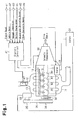
- Fig. 1 shows the schematic configuration of the internal combustion engine 10, which is an in-line four cylinder engine arranged in the automatic transmission vehicle, and the vicinity of the engine 10.
- an intake pipe 13 and an exhaust pipe 16 are each connected to four cylinders #1, #2, #3, #4, which are arranged in line in the engine 10.
- the intake pipe 13 supplies air to the cylinders #1, #2, #3, #4.
- the exhaust pipe 16 discharges exhaust gas, which is produced through combustion of air-fuel mixture in the cylinders #1, #2, #3, #4.
- the intake pipe 13 and the exhaust pipe 16 are each branched into four lines at the connecting portion with respect to the cylinders #1, #2, #3, #4.
- a throttle valve 12 regulating the amount of air drawn into the intake pipe 13 and an air flowmeter 47 measuring the amount of the drawn air are arranged in the intake pipe 13 at the positions upstream from the branching point of the intake pipe 13.
- a fuel supply pipe 14 is provided to conduct fuel, which is supplied from a fuel tank to the cylinders #1, #2, #3, #4 for combustion, to the cylinders #1, #2, #3, #4. under high pressure.
- Four fuel injections valves 15 through which the high-pressure fuel is injected directly into the cylinders #1, #2, #3, #4 are connected to the fuel supply pipe 14.
- Each of the cylinders #1, #2, #3, #4 has a piston reciprocating in the corresponding cylinder #1, #2, #3, #4 when the air-fuel mixture, which is the air supplied through the intake pipe 13 and the fuel injected through the fuel injection valves 15, is burned.
- the pistons are connected to a single crankshaft 11 through a connecting rod converting reciprocation of the corresponding piston to rotation.
- a first end of the crankshaft 11 is connected to the drive wheels through an automatic transmission 30, which automatically changes the transmission ratio, or,, in other words, the degree of speed reduction of the engine operation, in accordance with the operating state of the engine such as the traveling speed of the vehicle and the engine speed.
- a first pulley 34 is arranged at a second end of the crankshaft 11.
- a belt 36 is arranged around the first pulley 34 and a second pulley 35, which is provided at an end of an output shaft of a generator-motor 33.
- the generator-motor 33 generates power through rotation of the crankshaft 11 and charges the power in a battery 31.
- the generator-motor 33 functions also as a motor driving an auxiliary device such as an air conditioner (a compressor of the air conditioner, to be exact) when the rotation of the crankshaft 11 is stopped.
- An electromagnetic clutch 32 which selectively permits and prohibits operable connection between the crankshaft 11 and the generator-motor 33, is arranged at the joint portion between the crankshaft 11 and the first pulley 34.
- the engine 10 also has a starter 20. If the ignition switch is turned on when operation of the engine 10 is in a stopped state, the starter 20 rotates the crankshaft 11 by the power supplied from the battery 31, thus promoting autonomous operation of the engine 10.
- a large diameter portion 11a is formed at the first end of the crankshaft 11, which is connected to the automatic transmission 30.
- the large diameter portion 11a is press fitted into a ball bearing 26, which is a roller bearing.
- a disk-like ring gear 21 is arranged at a radially outside position of the ball bearing 26.
- the ring gear 21 has an inner race 23, which is arranged at a radially inner position of the ring gear 21.
- the inner race 23 is engaged with the outer circumference of the ball bearing 26.
- a disk-like outer race member 24 is arranged around the crankshaft 11.
- the outer race member 24 is opposed to the inner race 23 in a radial direction and has an outer race 25, which is arranged around the inner race 23.
- the flywheel 11b suppresses uneven rotation of the crankshaft 11.
- the teeth formed along the outer circumference of the ring gear 21 are constantly meshed with the teeth of a pinion gear 20b, which is arranged on an output shaft 20a of the starter 20.
- Rotation of the crankshaft 11 causes autonomous operation of the engine 10. Afterwards, when the rotational speed of the crankshaft 11 becomes higher than the rotational speed of the starter 20, which is the rotational speed of the ring gear 21 rotating together with the starter 20, the rotational speed of the outer race member 24 rotating together with the crankshaft 11 becomes higher than the rotational speed of the ring gear 21.
- the one-way clutch 22 then disengages the ring gear 21 and the outer race member 24 from each other, thus preventing the rotational force of the crankshaft 11 from being transmitted to the starter 20 through the outer race member 24 and the ring gear 21.
- the starter 20 and the ring gear 21 may be rotated only when necessary, such as when the engine 10 is started.
- the constant mesh type starter 20 does not consume the time for meshing the gears 20b, 21 with each other and thus reduces the time necessary for starting the engine 10.
- the engine 10 or the vehicle in which the engine 10 is mounted includes the following sensors as sensors detecting the operating state of the engine 10 or the vehicle.
- the electronic control unit 40 is configured mainly by a microcomputer that has a central processing unit (CPU), a program memory (a ROM), and a data memory (a RAM) and performs various types of control including control of the automatic transmission 30, control of the fuel injection valves 15, and control of the starter 20.
- the electronic control unit 40 includes an input section and drivers as peripheral circuits of the microcomputer.
- the input section receives the detection signals from the above-described sensors.
- the drivers drive various types of actuators in response to commands from the microcomputer.
- the sensors are electrically connected to the input section of the electronic control unit 40.
- An actuator related to transmission ratio control of the automatic transmission 30, the fuel injection valves 15, and the starter 20 are each electrically connected to an output section of the electronic control unit 40.
- the electronic control unit 40 performs control related to economy running by which the engine 10 is automatically stopped and restarted in accordance with the operating state of the vehicle in which the engine 10 is mounted and operation of the vehicle. Details of the control related to the economy running will hereafter be explained with reference to Fig. 3 .
- the electronic control unit 40 when the ignition switch (IG) of the vehicle that has been held in a stopped state is switched from the OFF position to the ON position by the driver, the electronic control unit 40 is activated. The electronic control unit 40 then sets the control mode related to the economy running to the mode indicating a normal stopped state of the engine operation, which is the mode 0. When the driver switches the ignition switch to the STA (start) position, the starter 20 is actuated and the crankshaft 11 is rotated, thus starting the engine 10. When starting of the engine 10 is completed and the engine 10 starts the autonomous operation, the electronic control unit 40 sets the control mode to the mode 1, which indicates an engine running state.
- the electronic control unit 40 performs a normal engine stopping procedure to stop the engine 10 and changes the control mode to the mode 0.
- the electromagnetic clutch 32 (see Fig. 1 ) connects the crankshaft 11 to the generator-motor 33. This causes the generator-motor 33 to rotate together with the crankshaft 11 and thus generate the power. The generated power is charged in the battery 31.
- the electronic control unit 40 changes the control mode from the mode 1 to the mode 2.
- the condition for automatically stopping the engine 10 may include the conditions described below:
- the electronic control unit 40 determines that the condition for automatically stopping the engine 10 is satisfied when it is determined that the above-described conditions are all met with reference to the detection signals of the sensors 42, 43, 44, 45, 46.
- the threshold values SPa, TWa, and VBATa by which it is determined whether the condition for automatically stopping the engine 10 is satisfied, are calculated in advance through experiments, for example, and stored in the program memory (the ROM) of the electronic control unit 40 (the microcomputer).
- the temperature TWa is set to the minimum value of such a range that combustion of the air-fuel ratio is not hampered when the engine 10 is restarted.
- the charge amount VBATa is set to the minimum value of such a range that the engine operation is allowed.
- the electronic control unit 40 stops injection of the fuel into the cylinders #1, #2, #3, #4 through the fuel injection valves 15, thus stopping operation of the engine 10.
- the electronic control unit 40 switches the control mode to the mode 3, which indicates an automatically stopped state of the engine operation.
- the control mode is the mode 3
- the crankshaft 11 and the generator-motor 33 are disengaged from each other by the electromagnetic clutch 32. This actuates the generator-motor 33 as the motor, so that the output of the motor actuates the auxiliary device such as the air conditioner (the compressor).
- the electronic control unit 40 changes the control mode from the mode 3 to the mode 4.
- the condition includes the conditions described below.
- the electronic control unit 40 determines that any one of the above-described conditions is met from the detection signals of the sensors 44, 45, 46, the electronic control unit 40 determines that the condition for restarting the engine 10 is satisfied.
- the constant mesh type starter 20 is actuated and the crankshaft 11 is rotated to restart the engine 10.
- the crankshaft 11 and the generator-motor 33 are then reconnected to each other by the electromagnetic clutch 32, thus allowing the generator-motor 33 to function as the power generator.
- the electronic control unit 40 sets the control mode to the mode 1.
- the electronic control unit 40 of the present embodiment is capable of reducing the fuel consumption of the engine 10 by automatically stopping and restarting the engine operation in accordance with the operating state of the engine 10 or the vehicle or the traveling state of the vehicle.
- the control mode is switched from the mode 2 to the mode 4, which is the mode for restarting the engine 10, without being set to the mode 3, before stopping of the engine 10 is completed.
- the speed of the engine 10 is in such a range that the engine 10 can restore the autonomous operation, or in other words, if the engine operation is restartable without employing the starter 20, the normal operation of the engine 10 is resumed by performing fuel injection or ignition in accordance with the operating state of the engine 10.
- the control mode is set to the mode 1.
- the speed of the engine 10 is in such a range that the engine 10 cannot restore the autonomous operation, or in other words, if the starter 20 must be employed to restart the engine 10, the engine 10 is started in the same manner as the normal engine starting.
- the engine operation is completely stopped when the normal engine starting is performed or when the engine 10 is restarted in accordance with the mode 4, the engine operation is not stopped when the control mode is switched from the mode 2 to the mode 4. Accordingly, when the engine 10 is restarted after the control mode has been switched in this manner, negative pressure remains in the intake pipe 13 in accordance with the engine speed at the time when the control mode was switched. In other words, compared to the case in which the engine operation is completely stopped, the amount of the air drawn into the cylinders is restricted by the amount corresponding to the negative pressure remaining in the intake pipe 13 when the engine operation is not stopped.
- the fuel is injected into the cylinders #1, #2, #3, #4 through the fuel injection valves 15 by the amount corresponding to an engine start fuel injection amount, which is set in advance in accordance with the temperature of the engine coolant. Accordingly, if the engine 10 is restarted using the starter 20 when the engine operation is not completely stopped and the intake air amount is restricted, the fuel injection amount becomes excessively great with respect to the intake air amount. This may deterirate the ignitability of the air-fuel mixture.
- the electronic control unit 40 of the present embodiment improves the restarting performance of the engine 10 when the engine operation is not completely stopped and the starter 20 is employed to restart the engine 10.
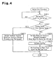
- Fig. 4 is a flowchart representing the restarting procedure of the engine 10, which is carried out by the electronic control unit 40.
- the restarting procedure is performed when the condition for restarting the engine 10 is satisfied and the engine operation is not completely stopped, after the condition for automatically stopping the engine 10 has been met.
- step S401 it is first determined whether the condition for restarting the engine 10 is satisfied when the condition for automatically stopping the engine 10 is met. Determination that the condition for restarting the engine 10 is satisfied is brought about if any one of the three above-described conditions (I) to (n) is met.
- the electronic control unit 40 calculates the engine speed based on the detection signal output by the engine speed sensor 41.
- the electronic control unit 40 also determines whether the current engine speed is greater than a critical engine speed (which is, for example, 500 rpm), which is an engine speed slightly lower than the idle engine speed (which is, for example, 600 to 800 rpm) (step S402).
- a critical engine speed which is, for example, 500 rpm
- the electronic control unit 40 determines that the engine speed is in such a range that the engine 10 can restore the autonomous operation and restarts the engine 10 without employing the starter 20 (step S403).
- the electronic control unit 40 calculates the fuel injection amount, the fuel injection timing, and the ignition timing in accordance with the depression amount of the accelerator pedal to start the engine operation, in the same manner as the normal engine starting.
- step S402 when it is determined that the engine speed is lower than or equal to the critical engine speed (step S402: NO), it is also determined that the engine speed is in such a range that the autonomous engine operation cannot be restored.
- a negative pressure release procedure is performed in order to release the negative pressure remaining in the intake pipe 13, caused by the engine operation (step S404).
- the throttle valve 12, which is arranged in the intake pipe 13 is maintained open for the period of 250 ms since the determination that the engine speed is in such a range that the autonomous engine operation cannot be restored in step S402.
- the starter 20 is actuated to rotate the crankshaft 11 (step S405). Fuel is then injected from the fuel injection valves 15 by the amount corresponding to the engine start fuel injection amount in accordance with the engine coolant temperature detected by the coolant temperature sensor 43 and the produced air-fuel mixture is subjected to ignition (step S406). Specifically, the engine start fuel injection amount is calculated in advance based on experiment results or the like and stored in the program memory (the ROM) of the electronic control unit 40 as, for example, a map setting the fuel injection amount for the respective values of the engine coolant temperature.
- the starter 20 is activated when 100 ms elapses since the end of opening of the throttle valve 12, which is the negative pressure release procedure. In other words, release of the negative pressure from the intake pipe 13 is accomplished by temporarily opening the throttle valve 12 before the various types of control for restarting the engine 10 using the starter 20 are started. This maintains control performance and flexibility of each type of control when the engine 10 is restarted.
- Fig. 5 is a timing chart representing an example of operation in accordance with the restarting procedure.
- Section (a) illustrates switching of traveling modes
- section (b) illustrates change of the engine speed (represented by the solid lines)
- section (c) illustrates change of the opening degree of the throttle valve 12.
- Section (d) illustrates the timings at which the starter 20 is actuated
- section (e) illustrates the timings at which the engine start fuel injection is performed.
- the electronic control unit 40 changes the control mode from the mode 1 to the mode 2. This regulates the opening degree of the throttle valve 12 to a value corresponding to a fully closed state or a substantially fully closed state. The engine speed then gradually drops toward a stopped state until the condition for restarting the engine 10 is met at the time point t2.
- the throttle valve 12 is maintained open for only 250 ms till the time point t3, as has been described.
- the starter 20 is actuated at the time point t4, which is after 100 ms since closure of the throttle valve 12, and the engine start fuel injection is performed at, for example, the time point t5, while the starter 20 is operated from the time point t4 to the time point t6.
- the starter 20 is de-actuated and the control mode is switched from the mode 4 to the mode 1.
- a reference engine speed change is represented by the double-dotted chain lines.
- the reference engine speed change is an example of change of the engine speed in the case in which the opening procedure of the throttle valve 12 (the negative pressure release procedure) is carried out despite the fact that, for example, the engine speed is in such a range that the autonomous engine operation can be restored.
- the engine speed may not be lowered sufficiently.
- the controller 40 of the engine 10 according to the present invention has the advantages described below.
- the opening degree of the throttle valve 12 is constant throughout the period in which the throttle valve 12 is held open, the opening degree of the throttle valve 12 is varied in accordance with the engine speed. Specifically, the opening degree of the throttle valve 12 is set to a greater value as the engine speed at the time when the condition for restarting the engine 10 is satisfied becomes higher. This adds the advantage (5), as described below, to the above-described advantages (1) to (4).
- the present invention is not restricted to the configuration illustrated in the above-described embodiment but may be embodied in modified forms, for example, as described below.
- the conditions for automatically stopping and restarting the engine 10 are not restricted to those illustrated in the above embodiment. These conditions may be modified in any suitable manners as long as the conditions ensure determination, for example, whether the vehicle is temporarily stopped or whether the vehicle is to be restarted after having been in a temporarily stopped state.
- the configuration of the one-way clutch 22 is not restricted to that of the above illustrated embodiment.
- the one-way clutch 22 may be configured in any suitable manners as long as the starter 20 is a constant mesh type and the one-way clutch 22 permits transmission of rotation from the starter 20 to the crankshaft 11 but prohibits transmission of rotation from the crankshaft 11 to the starter 20.
- the internal combustion engine 10 which is the control target, is a direct injection type engine in which the fuel is injected directly into the cylinders #1, #2, #3, #4.
- the engine 10 is not restricted to this type but may be a port injection type internal combustion engine having a fuel injection valve arranged in an intake pipe.
- the cylinders of the internal combustion engine in which the present invention is employed may be arranged in any suitable manner other than the in-line four-cylinder arrangement.
- the vehicle in which the controller 40 of the engine 10 is mounted is not restricted to an automatic transmission vehicle but may be a manual transmission vehicle, or an MT vehicle.
- one of the conditions for automatically stopping or restarting the engine 10 may be that the clutch pedal, not the brake pedal as in the case of the AT vehicle, is released or depressed.
- the period in which the throttle valve 12 is maintained open may be varied in accordance with, for example, the level of the negative pressure remaining in the intake pipe 13. In this case, it is preferable to set this period in such a range that the engine speed is prevented from excessively rising due to opening of the throttle valve 12.
- the critical engine speed is not restricted to 500 rpm.
- the critical engine speed may be set to any suitable value as long as the value is in such a range that the engine 10 cannot be restarted without the starter 20 and is smaller than the idle engine speed so that the engine speed does not increase excessively when the negative pressure release procedure is carried out.
Landscapes
- Engineering & Computer Science (AREA)
- Chemical & Material Sciences (AREA)
- Combustion & Propulsion (AREA)
- Mechanical Engineering (AREA)
- General Engineering & Computer Science (AREA)
- Control Of Vehicle Engines Or Engines For Specific Uses (AREA)
- Electrical Control Of Air Or Fuel Supplied To Internal-Combustion Engine (AREA)
- Output Control And Ontrol Of Special Type Engine (AREA)
Claims (4)
- Steuergerät (40) von einem Fahrzeugverbrennungsmotor (10), der unter einer vorgeschriebenen Bedingung, die sich auf einen Betrieb des Fahrzeugs bezieht, automatisch gestoppt und erneut gestartet wird, wobei der Motor (10) eine Ausgabewelle (20a), einen Anlasser (20), der permanent mit der Ausgabewelle (20a) in Eingriff steht, und ein Drosselventil (12), das eine Ansaugluftmenge, die zum Motor (10) geliefert wird, regelt, enthält, wobei, nachdem der Motor (10) einer automatischen Stoppprozedur ausgesetzt wurde, das Steuergerät (40) den Motor (10) erneut startet, wenn eine Neustartbedingung erfüllt ist, wobei das Steuergerät (40) den Anlasser verwendet, um den Motor (10) erneut zu starten, falls sich eine Motordrehzahl in solch einem vorgegeben Bereich befindet, dass ein autonomer Betrieb des Motors (10) nicht wiederhergestellt werden kann, wobei
das Steuergerät (40) das Drosselventil (12) unter der Bedingung vorübergehend öffnet, dass die Motordrehzahl zum Zeitpunkt, wenn die Neustartbedingung erfüllt ist, nicht Null ist und sich diese in dem vorgegebenen Bereich befindet, und wobei
ein Zeitabschnitt, in dem das Drosselventil (12) offen gehalten wird, auf einen Zeitabschnitt von einer Erfüllung der Neustartbedingung bis zu einer Freigabe eines Unterdrucks, der in einem Ansaugrohr (13) des Motors (10) aufgrund von Rotation der Ausgabewelle (20a) produziert wird, festgesetzt wird, wobei das Steuergerät dadurch gekennzeichnet ist, dass
in dem Zeitabschnitt, in dem das Drosselventil (12) offen gehalten wird, ein Öffnungsgrad des Drosselventils (12) auf einen größeren Wert festgesetzt wird, wenn die Motordrehzahl zum Zeitpunkt, wenn die Neustartbedingung erfüllt ist, höher wird. - Steuergerät nach Anspruch 1, wobei eine obere Grenzmotordrehzahl des vorgegebenen Bereichs auf einen Wert festgesetzt wird, der kleiner als eine Leerlaufgeschwindigkeit des Motors (10) ist.
- Steuergerät nach Anspruch 1 oder 2, wobei, wenn die Neustartbedingung erfüllt ist, der Anlasser (20) betätigt wird, nachdem das Drosselventil (12) vorübergehend geöffnet wird.
- Steuergerät (40) nach Anspruch 3, wobei der Anlasser betätigt wird, nachdem eine vorgegebene Zeitspanne seit einem Öffnen des Drosselventils (12) für eine vorgegebene Zeitspanne beendet ist.
Applications Claiming Priority (1)
| Application Number | Priority Date | Filing Date | Title |
|---|---|---|---|
| JP2008270025A JP5036682B2 (ja) | 2008-10-20 | 2008-10-20 | 車載内燃機関の制御装置 |
Publications (3)
| Publication Number | Publication Date |
|---|---|
| EP2177740A2 EP2177740A2 (de) | 2010-04-21 |
| EP2177740A3 EP2177740A3 (de) | 2012-04-18 |
| EP2177740B1 true EP2177740B1 (de) | 2015-12-16 |
Family
ID=41571422
Family Applications (1)
| Application Number | Title | Priority Date | Filing Date |
|---|---|---|---|
| EP09013173.1A Not-in-force EP2177740B1 (de) | 2008-10-20 | 2009-10-19 | Steuerung für Verbrennungsmotor von Fahrzeugen |
Country Status (2)
| Country | Link |
|---|---|
| EP (1) | EP2177740B1 (de) |
| JP (1) | JP5036682B2 (de) |
Families Citing this family (7)
| Publication number | Priority date | Publication date | Assignee | Title |
|---|---|---|---|---|
| JP3181187B2 (ja) | 1995-01-24 | 2001-07-03 | 株式会社丸島アクアシステム | 液圧式ゲート開閉装置 |
| DE102011090149A1 (de) * | 2011-12-30 | 2013-07-04 | Robert Bosch Gmbh | Verfahren zur Ansteuerung eines Organs im Luftzufuhrtrakt einer Brennkraftmaschine, insbesondere einer Drosselklappe |
| GB2517751B (en) * | 2013-08-30 | 2020-01-29 | Ford Global Tech Llc | A method of controlling the stopping and starting of an engine of a motor vehicle |
| JP6504006B2 (ja) * | 2015-09-29 | 2019-04-24 | 株式会社デンソー | エンジンの制御装置 |
| CN106894900A (zh) * | 2015-12-18 | 2017-06-27 | 北汽福田汽车股份有限公司 | 发动机的控制方法 |
| JP2019173586A (ja) * | 2018-03-27 | 2019-10-10 | 本田技研工業株式会社 | 内燃機関の制御装置 |
| JP7616120B2 (ja) * | 2022-02-25 | 2025-01-17 | トヨタ自動車株式会社 | 車両の制御装置 |
Family Cites Families (6)
| Publication number | Priority date | Publication date | Assignee | Title |
|---|---|---|---|---|
| JP4595242B2 (ja) * | 2001-05-17 | 2010-12-08 | トヨタ自動車株式会社 | 車両用エンジンの制御装置 |
| JP3707408B2 (ja) * | 2001-08-29 | 2005-10-19 | トヨタ自動車株式会社 | 内燃機関の停止・始動制御装置 |
| JP4012893B2 (ja) * | 2004-06-11 | 2007-11-21 | トヨタ自動車株式会社 | 内燃機関の制御装置 |
| JP4760554B2 (ja) * | 2006-06-06 | 2011-08-31 | トヨタ自動車株式会社 | 内燃機関の制御システム |
| JP4276680B2 (ja) * | 2007-02-06 | 2009-06-10 | 株式会社日本自動車部品総合研究所 | 多気筒内燃機関の制御装置 |
| JP4858234B2 (ja) * | 2007-03-02 | 2012-01-18 | トヨタ自動車株式会社 | 内燃機関の停止始動制御装置 |
-
2008
- 2008-10-20 JP JP2008270025A patent/JP5036682B2/ja not_active Expired - Fee Related
-
2009
- 2009-10-19 EP EP09013173.1A patent/EP2177740B1/de not_active Not-in-force
Also Published As
| Publication number | Publication date |
|---|---|
| JP2010096155A (ja) | 2010-04-30 |
| EP2177740A2 (de) | 2010-04-21 |
| JP5036682B2 (ja) | 2012-09-26 |
| EP2177740A3 (de) | 2012-04-18 |
Similar Documents
| Publication | Publication Date | Title |
|---|---|---|
| US6763903B2 (en) | Automatic stop/ start-up controlling device of an engine | |
| US8494711B2 (en) | Automated start-stop systems and methods for internal combustion engines | |
| EP2177740B1 (de) | Steuerung für Verbrennungsmotor von Fahrzeugen | |
| JP4835537B2 (ja) | エンジンの自動停止装置 | |
| US8554453B2 (en) | Device and method for controlling starter, and vehicle | |
| US7941266B2 (en) | Method and device for controlling an internal combustion engine in stop/start operation | |
| JP2001082202A (ja) | 内燃機関の始動制御装置 | |
| US8433502B2 (en) | Control method and control device for engine | |
| JP2009299598A (ja) | エンジンの制御装置 | |
| EP2184470A2 (de) | Steuerung eines Verbrennungsmotors eines Fahrzeugs | |
| EP2216532B1 (de) | Steuergerät für Fahrzeugverbrennungsmotor | |
| JP2008303788A (ja) | 内燃機関の自動停止装置 | |
| JP5413325B2 (ja) | エンジン停止始動制御装置 | |
| JP2011075011A (ja) | エンジン停止始動制御装置 | |
| EP2396530A1 (de) | Steuerung eines verbrennungsmotors | |
| JP2004036428A (ja) | 内燃機関の制御装置 | |
| JP4558049B2 (ja) | 筒内直接噴射式エンジンの制御装置 | |
| JP2018048611A (ja) | ディーゼルエンジンの制御装置 | |
| JP2012136980A (ja) | エンジン回転停止制御装置 | |
| JP2012087733A (ja) | 内燃機関の燃料噴射制御方法 | |
| JP2008215299A (ja) | 手動変速機付き車両用エンジンの自動停止始動装置 | |
| JP2008286127A (ja) | 車両制御装置 | |
| JP4665940B2 (ja) | 車両用エンジンの制御装置 | |
| JP4407832B2 (ja) | エンジンの制御装置 | |
| JP4379327B2 (ja) | 車両の制御装置 |
Legal Events
| Date | Code | Title | Description |
|---|---|---|---|
| PUAI | Public reference made under article 153(3) epc to a published international application that has entered the european phase |
Free format text: ORIGINAL CODE: 0009012 |
|
| 17P | Request for examination filed |
Effective date: 20091019 |
|
| AK | Designated contracting states |
Kind code of ref document: A2 Designated state(s): AT BE BG CH CY CZ DE DK EE ES FI FR GB GR HR HU IE IS IT LI LT LU LV MC MK MT NL NO PL PT RO SE SI SK SM TR |
|
| AX | Request for extension of the european patent |
Extension state: AL BA RS |
|
| RTI1 | Title (correction) |
Free format text: CONTROLLER OF VEHICLE INTERNAL COMBUSTION ENGINE |
|
| PUAL | Search report despatched |
Free format text: ORIGINAL CODE: 0009013 |
|
| RIC1 | Information provided on ipc code assigned before grant |
Ipc: F02N 11/08 20060101ALI20120308BHEP Ipc: F02D 41/04 20060101ALN20120308BHEP Ipc: F02D 33/02 20060101ALI20120308BHEP Ipc: F02D 41/06 20060101AFI20120308BHEP |
|
| AK | Designated contracting states |
Kind code of ref document: A3 Designated state(s): AT BE BG CH CY CZ DE DK EE ES FI FR GB GR HR HU IE IS IT LI LT LU LV MC MK MT NL NO PL PT RO SE SI SK SM TR |
|
| AX | Request for extension of the european patent |
Extension state: AL BA RS |
|
| RAP1 | Party data changed (applicant data changed or rights of an application transferred) |
Owner name: TOYOTA JIDOSHA KABUSHIKI KAISHA |
|
| RIC1 | Information provided on ipc code assigned before grant |
Ipc: F02D 33/02 20060101ALI20150429BHEP Ipc: F02D 11/10 20060101ALN20150429BHEP Ipc: F02D 41/06 20060101AFI20150429BHEP Ipc: F02N 11/08 20060101ALI20150429BHEP Ipc: F02D 41/04 20060101ALN20150429BHEP Ipc: F02N 11/00 20060101ALI20150429BHEP |
|
| GRAP | Despatch of communication of intention to grant a patent |
Free format text: ORIGINAL CODE: EPIDOSNIGR1 |
|
| INTG | Intention to grant announced |
Effective date: 20150612 |
|
| GRAS | Grant fee paid |
Free format text: ORIGINAL CODE: EPIDOSNIGR3 |
|
| GRAA | (expected) grant |
Free format text: ORIGINAL CODE: 0009210 |
|
| RIN1 | Information on inventor provided before grant (corrected) |
Inventor name: HATTA, YUUJI Inventor name: NAKAMURA, YOSHIFUMI Inventor name: OKAMURA, KOJI Inventor name: YOSHIHARA, MASATOMO Inventor name: UCHIDA, AKITO Inventor name: MASUDA, SATOSHI |
|
| AK | Designated contracting states |
Kind code of ref document: B1 Designated state(s): AT BE BG CH CY CZ DE DK EE ES FI FR GB GR HR HU IE IS IT LI LT LU LV MC MK MT NL NO PL PT RO SE SI SK SM TR |
|
| REG | Reference to a national code |
Ref country code: GB Ref legal event code: FG4D |
|
| REG | Reference to a national code |
Ref country code: CH Ref legal event code: EP |
|
| REG | Reference to a national code |
Ref country code: IE Ref legal event code: FG4D |
|
| REG | Reference to a national code |
Ref country code: AT Ref legal event code: REF Ref document number: 765672 Country of ref document: AT Kind code of ref document: T Effective date: 20160115 |
|
| REG | Reference to a national code |
Ref country code: DE Ref legal event code: R096 Ref document number: 602009035195 Country of ref document: DE |
|
| REG | Reference to a national code |
Ref country code: NL Ref legal event code: MP Effective date: 20151216 |
|
| REG | Reference to a national code |
Ref country code: LT Ref legal event code: MG4D |
|
| PG25 | Lapsed in a contracting state [announced via postgrant information from national office to epo] |
Ref country code: HR Free format text: LAPSE BECAUSE OF FAILURE TO SUBMIT A TRANSLATION OF THE DESCRIPTION OR TO PAY THE FEE WITHIN THE PRESCRIBED TIME-LIMIT Effective date: 20151216 Ref country code: NO Free format text: LAPSE BECAUSE OF FAILURE TO SUBMIT A TRANSLATION OF THE DESCRIPTION OR TO PAY THE FEE WITHIN THE PRESCRIBED TIME-LIMIT Effective date: 20160316 Ref country code: LT Free format text: LAPSE BECAUSE OF FAILURE TO SUBMIT A TRANSLATION OF THE DESCRIPTION OR TO PAY THE FEE WITHIN THE PRESCRIBED TIME-LIMIT Effective date: 20151216 |
|
| REG | Reference to a national code |
Ref country code: AT Ref legal event code: MK05 Ref document number: 765672 Country of ref document: AT Kind code of ref document: T Effective date: 20151216 |
|
| PG25 | Lapsed in a contracting state [announced via postgrant information from national office to epo] |
Ref country code: FI Free format text: LAPSE BECAUSE OF FAILURE TO SUBMIT A TRANSLATION OF THE DESCRIPTION OR TO PAY THE FEE WITHIN THE PRESCRIBED TIME-LIMIT Effective date: 20151216 Ref country code: LV Free format text: LAPSE BECAUSE OF FAILURE TO SUBMIT A TRANSLATION OF THE DESCRIPTION OR TO PAY THE FEE WITHIN THE PRESCRIBED TIME-LIMIT Effective date: 20151216 Ref country code: SE Free format text: LAPSE BECAUSE OF FAILURE TO SUBMIT A TRANSLATION OF THE DESCRIPTION OR TO PAY THE FEE WITHIN THE PRESCRIBED TIME-LIMIT Effective date: 20151216 Ref country code: GR Free format text: LAPSE BECAUSE OF FAILURE TO SUBMIT A TRANSLATION OF THE DESCRIPTION OR TO PAY THE FEE WITHIN THE PRESCRIBED TIME-LIMIT Effective date: 20160317 Ref country code: NL Free format text: LAPSE BECAUSE OF FAILURE TO SUBMIT A TRANSLATION OF THE DESCRIPTION OR TO PAY THE FEE WITHIN THE PRESCRIBED TIME-LIMIT Effective date: 20151216 |
|
| PG25 | Lapsed in a contracting state [announced via postgrant information from national office to epo] |
Ref country code: ES Free format text: LAPSE BECAUSE OF FAILURE TO SUBMIT A TRANSLATION OF THE DESCRIPTION OR TO PAY THE FEE WITHIN THE PRESCRIBED TIME-LIMIT Effective date: 20151216 Ref country code: CZ Free format text: LAPSE BECAUSE OF FAILURE TO SUBMIT A TRANSLATION OF THE DESCRIPTION OR TO PAY THE FEE WITHIN THE PRESCRIBED TIME-LIMIT Effective date: 20151216 Ref country code: IT Free format text: LAPSE BECAUSE OF FAILURE TO SUBMIT A TRANSLATION OF THE DESCRIPTION OR TO PAY THE FEE WITHIN THE PRESCRIBED TIME-LIMIT Effective date: 20151216 |
|
| REG | Reference to a national code |
Ref country code: DE Ref legal event code: R084 Ref document number: 602009035195 Country of ref document: DE |
|
| PG25 | Lapsed in a contracting state [announced via postgrant information from national office to epo] |
Ref country code: SM Free format text: LAPSE BECAUSE OF FAILURE TO SUBMIT A TRANSLATION OF THE DESCRIPTION OR TO PAY THE FEE WITHIN THE PRESCRIBED TIME-LIMIT Effective date: 20151216 Ref country code: EE Free format text: LAPSE BECAUSE OF FAILURE TO SUBMIT A TRANSLATION OF THE DESCRIPTION OR TO PAY THE FEE WITHIN THE PRESCRIBED TIME-LIMIT Effective date: 20151216 Ref country code: AT Free format text: LAPSE BECAUSE OF FAILURE TO SUBMIT A TRANSLATION OF THE DESCRIPTION OR TO PAY THE FEE WITHIN THE PRESCRIBED TIME-LIMIT Effective date: 20151216 Ref country code: PT Free format text: LAPSE BECAUSE OF FAILURE TO SUBMIT A TRANSLATION OF THE DESCRIPTION OR TO PAY THE FEE WITHIN THE PRESCRIBED TIME-LIMIT Effective date: 20160418 Ref country code: SK Free format text: LAPSE BECAUSE OF FAILURE TO SUBMIT A TRANSLATION OF THE DESCRIPTION OR TO PAY THE FEE WITHIN THE PRESCRIBED TIME-LIMIT Effective date: 20151216 Ref country code: RO Free format text: LAPSE BECAUSE OF FAILURE TO SUBMIT A TRANSLATION OF THE DESCRIPTION OR TO PAY THE FEE WITHIN THE PRESCRIBED TIME-LIMIT Effective date: 20151216 Ref country code: IS Free format text: LAPSE BECAUSE OF FAILURE TO SUBMIT A TRANSLATION OF THE DESCRIPTION OR TO PAY THE FEE WITHIN THE PRESCRIBED TIME-LIMIT Effective date: 20160416 |
|
| REG | Reference to a national code |
Ref country code: DE Ref legal event code: R097 Ref document number: 602009035195 Country of ref document: DE |
|
| PLBE | No opposition filed within time limit |
Free format text: ORIGINAL CODE: 0009261 |
|
| STAA | Information on the status of an ep patent application or granted ep patent |
Free format text: STATUS: NO OPPOSITION FILED WITHIN TIME LIMIT |
|
| PG25 | Lapsed in a contracting state [announced via postgrant information from national office to epo] |
Ref country code: PL Free format text: LAPSE BECAUSE OF FAILURE TO SUBMIT A TRANSLATION OF THE DESCRIPTION OR TO PAY THE FEE WITHIN THE PRESCRIBED TIME-LIMIT Effective date: 20151216 Ref country code: DK Free format text: LAPSE BECAUSE OF FAILURE TO SUBMIT A TRANSLATION OF THE DESCRIPTION OR TO PAY THE FEE WITHIN THE PRESCRIBED TIME-LIMIT Effective date: 20151216 |
|
| 26N | No opposition filed |
Effective date: 20160919 |
|
| PG25 | Lapsed in a contracting state [announced via postgrant information from national office to epo] |
Ref country code: BE Free format text: LAPSE BECAUSE OF FAILURE TO SUBMIT A TRANSLATION OF THE DESCRIPTION OR TO PAY THE FEE WITHIN THE PRESCRIBED TIME-LIMIT Effective date: 20151216 |
|
| PG25 | Lapsed in a contracting state [announced via postgrant information from national office to epo] |
Ref country code: SI Free format text: LAPSE BECAUSE OF FAILURE TO SUBMIT A TRANSLATION OF THE DESCRIPTION OR TO PAY THE FEE WITHIN THE PRESCRIBED TIME-LIMIT Effective date: 20151216 |
|
| REG | Reference to a national code |
Ref country code: CH Ref legal event code: PL |
|
| GBPC | Gb: european patent ceased through non-payment of renewal fee |
Effective date: 20161019 |
|
| REG | Reference to a national code |
Ref country code: IE Ref legal event code: MM4A |
|
| REG | Reference to a national code |
Ref country code: FR Ref legal event code: ST Effective date: 20170630 |
|
| PG25 | Lapsed in a contracting state [announced via postgrant information from national office to epo] |
Ref country code: LI Free format text: LAPSE BECAUSE OF NON-PAYMENT OF DUE FEES Effective date: 20161031 Ref country code: GB Free format text: LAPSE BECAUSE OF NON-PAYMENT OF DUE FEES Effective date: 20161019 Ref country code: FR Free format text: LAPSE BECAUSE OF NON-PAYMENT OF DUE FEES Effective date: 20161102 Ref country code: CH Free format text: LAPSE BECAUSE OF NON-PAYMENT OF DUE FEES Effective date: 20161031 |
|
| PG25 | Lapsed in a contracting state [announced via postgrant information from national office to epo] |
Ref country code: LU Free format text: LAPSE BECAUSE OF NON-PAYMENT OF DUE FEES Effective date: 20161019 |
|
| PG25 | Lapsed in a contracting state [announced via postgrant information from national office to epo] |
Ref country code: IE Free format text: LAPSE BECAUSE OF NON-PAYMENT OF DUE FEES Effective date: 20161019 |
|
| PG25 | Lapsed in a contracting state [announced via postgrant information from national office to epo] |
Ref country code: CY Free format text: LAPSE BECAUSE OF FAILURE TO SUBMIT A TRANSLATION OF THE DESCRIPTION OR TO PAY THE FEE WITHIN THE PRESCRIBED TIME-LIMIT Effective date: 20151216 Ref country code: HU Free format text: LAPSE BECAUSE OF FAILURE TO SUBMIT A TRANSLATION OF THE DESCRIPTION OR TO PAY THE FEE WITHIN THE PRESCRIBED TIME-LIMIT; INVALID AB INITIO Effective date: 20091019 |
|
| PG25 | Lapsed in a contracting state [announced via postgrant information from national office to epo] |
Ref country code: TR Free format text: LAPSE BECAUSE OF FAILURE TO SUBMIT A TRANSLATION OF THE DESCRIPTION OR TO PAY THE FEE WITHIN THE PRESCRIBED TIME-LIMIT Effective date: 20151216 Ref country code: MT Free format text: LAPSE BECAUSE OF NON-PAYMENT OF DUE FEES Effective date: 20161031 Ref country code: MC Free format text: LAPSE BECAUSE OF FAILURE TO SUBMIT A TRANSLATION OF THE DESCRIPTION OR TO PAY THE FEE WITHIN THE PRESCRIBED TIME-LIMIT Effective date: 20151216 Ref country code: MK Free format text: LAPSE BECAUSE OF FAILURE TO SUBMIT A TRANSLATION OF THE DESCRIPTION OR TO PAY THE FEE WITHIN THE PRESCRIBED TIME-LIMIT Effective date: 20151216 |
|
| PG25 | Lapsed in a contracting state [announced via postgrant information from national office to epo] |
Ref country code: BG Free format text: LAPSE BECAUSE OF FAILURE TO SUBMIT A TRANSLATION OF THE DESCRIPTION OR TO PAY THE FEE WITHIN THE PRESCRIBED TIME-LIMIT Effective date: 20151216 |
|
| PGFP | Annual fee paid to national office [announced via postgrant information from national office to epo] |
Ref country code: DE Payment date: 20181009 Year of fee payment: 10 |
|
| REG | Reference to a national code |
Ref country code: DE Ref legal event code: R119 Ref document number: 602009035195 Country of ref document: DE |
|
| PG25 | Lapsed in a contracting state [announced via postgrant information from national office to epo] |
Ref country code: DE Free format text: LAPSE BECAUSE OF NON-PAYMENT OF DUE FEES Effective date: 20200501 |