EP2174570B1 - Rollenausziehführung - Google Patents
Rollenausziehführung Download PDFInfo
- Publication number
- EP2174570B1 EP2174570B1 EP09007350A EP09007350A EP2174570B1 EP 2174570 B1 EP2174570 B1 EP 2174570B1 EP 09007350 A EP09007350 A EP 09007350A EP 09007350 A EP09007350 A EP 09007350A EP 2174570 B1 EP2174570 B1 EP 2174570B1
- Authority
- EP
- European Patent Office
- Prior art keywords
- roller
- pull
- rail
- claw
- tilt
- Prior art date
- Legal status (The legal status is an assumption and is not a legal conclusion. Google has not performed a legal analysis and makes no representation as to the accuracy of the status listed.)
- Active
Links
Images





Classifications
-
- A—HUMAN NECESSITIES
- A47—FURNITURE; DOMESTIC ARTICLES OR APPLIANCES; COFFEE MILLS; SPICE MILLS; SUCTION CLEANERS IN GENERAL
- A47B—TABLES; DESKS; OFFICE FURNITURE; CABINETS; DRAWERS; GENERAL DETAILS OF FURNITURE
- A47B88/00—Drawers for tables, cabinets or like furniture; Guides for drawers
- A47B88/50—Safety devices or the like for drawers
- A47B88/57—Safety devices or the like for drawers preventing complete withdrawal of the drawer
-
- A—HUMAN NECESSITIES
- A47—FURNITURE; DOMESTIC ARTICLES OR APPLIANCES; COFFEE MILLS; SPICE MILLS; SUCTION CLEANERS IN GENERAL
- A47B—TABLES; DESKS; OFFICE FURNITURE; CABINETS; DRAWERS; GENERAL DETAILS OF FURNITURE
- A47B88/00—Drawers for tables, cabinets or like furniture; Guides for drawers
- A47B88/40—Sliding drawers; Slides or guides therefor
- A47B88/453—Actuated drawers
- A47B88/46—Actuated drawers operated by mechanically-stored energy, e.g. by springs
- A47B88/467—Actuated drawers operated by mechanically-stored energy, e.g. by springs self-closing
Definitions
- the present invention relates to a Rollenauszieh arrangement for pulling out a furniture part of a furniture body in a withdrawal direction and for inserting the furniture part in the furniture body in a direction of insertion with at least one guide rail and at least one guided in this role and a Diseinzugsvorraum with a spring-loaded, tiltable and slidably mounted tilting slide for retracting the furniture part in the insertion direction.
- Rollenauszieh exiten this type are known per se.
- the self-closing device is used to automatically pull the furniture part completely in the direction of insertion into the furniture body, ie in the closed position, after the furniture part has been inserted a certain distance in the insertion direction, for example by hand in the furniture body.
- various solutions are known with tilting valves. It is also known to provide such intake mechanisms with insertion dampers to dampen the retraction movement of the Rollenauszieh Entry in the last section.
- Such a damped pull-in mechanism or self-closing device, in which the tilting slide cooperates with a slide-in damper is for example from EP 1 532 892 A1 known.
- the tilting slide said self-closing devices cooperate with a driver, which is arranged on the extendable furniture part.
- a driver which is arranged on the extendable furniture part.
- Similar Diseinzugsvoriquesen, but without damper go for example from the AT 401 334 B in which also a displaceable against the force of a spring tilt slide is available.
- the tilting slide is arranged tiltable about a tilting axis on a slide which can be moved in a straight line in the pull-out direction of the drawer against the force of the spring.
- known Adeinzugsvorraum is also a tilt slide available, which is displaceable along a guideway against the force of a spring.
- the guideway has on a straight portion a bent portion which causes the pivoting of the tilting slide about an imaginary tilting axis in its tilted end position.
- Object of the present invention is to provide a generic Rollenauszieh arrangement in which with as few parts and as few processing steps high reliability can be guaranteed.
- the tilting slide has a gripper, which for feeding the furniture part in the insertion direction on the roller attacks.
- the tilting slide engages itself via its associated gripper on a roll of Rollenauszieh arrangement. It can therefore be applied to additional and common in the prior art driver such. Hook or similarly shaped parts on which the tilting slide attacks, be waived. This saves on the one hand processing steps, on the other hand also parts.
- a Rollenauszieh arrangement can also be built very compact. A particular advantage, however, lies in the fact that, despite sufficient movement play, a high level of operational reliability can be ensured.
- roller extension guide is rotatably mounted, preferably rotatably mounted, on a second rail of the roller extension guide, preferably by means of a roller rotation axis fastened to the second rail. It is thus preferred that at least one roller is rotatably mounted on a rail.
- additional rollers may be rotatably mounted or fastened on the rails of the roller extension guide, preferably by means of their roller pivot axes. The role or roles preferably have a supporting function.
- roller extension guides according to the invention can also be designed with conventional carriages in which balls and / or rollers are rotatably mounted.
- the guide rail may be, for example, the rail, which is fixed to the furniture body.
- the second rail is then conveniently the rail of Rollenauszieh Entry, which is attached to the relative to the furniture body slidably mounted furniture part.
- the guide rail and the second rail are then conveniently displaceably mounted by means of said rollers and / or carriages.
- On two opposite sides of the furniture part can ever be arranged such a Rollenauszieh arrangement.
- the Rollenauszieh Entry may each have at least one further rail, for example, a middle rail, which is relatively movable or displaceable both to the guide rail, and to the second rail.
- Roller extension guides according to the invention can thus also be designed as differential slide guides known per se.
- a Rollenauszieh Inventory, in which on each side of the furniture part three rails slidably to each other, are stored in each other, is in itself eg in the EP 1 532 892 A1 shown.
- the tilting slide has a gripper which engages for retraction of the furniture part in the direction of insertion on the roller.
- the retraction of the furniture part includes two sections. First, the gripper of the tilting slide must engage the roller. This is referred to below as the contacting process. This is followed by the actual pulling-in process in which the self-closing device pulls over the tilting slide on the roller or the second rail connected thereto in the insertion direction.
- the above-mentioned retraction of the furniture part refers both to the attacking process as well as the Einziehvorgang.
- both the contacting operation and the pulling-in operation are achieved by the engagement of the gripper of the gripper Tilting slide on the roller takes place.
- a method for operating such, according to the invention Rollenauszieh Installationen can then provide that the tilting slide is tilted by hitting the roller on the gripper from a first tilted position to the second tilted position, which is brought by this tilting of the gripper and the roller engaged with each other and thereafter the roller is pulled on the gripper of the tilting slide hanging from the tilting slide in the insertion direction.
- the second rail is thus retracted by the gripper acts directly on the roller and thus pulled on the roller.
- the gripping of the gripper on the roller takes place only during the contacting process. It can therefore also be provided that the retraction of the furniture part in the insertion direction only partially, ie z. B. only the contacting process, takes place by the attack of the gripper on the roller.
- the insertion process can be provided in these variants of the invention, other means with which the tilt slide on the second rail.
- a preferred group of embodiments of the invention provides that on the tilt slide a first coupling part is arranged and on the second rail, a second coupling part is arranged, wherein the coupling parts are dissolved in a first tilted position of the tilting slide from each other and in a second tilted position of Tilting slide are engaged with each other, wherein in the first tilt position, the second rail and the tilt slide in the extension direction and / or in the insertion direction relative to each other are movable and in the second tilt position, the second rail and the tilt slide with respect to a movement in the pull-out direction and / or in the insertion direction with each other are positively coupled.
- Forced coupling means in this context in particular, that rail and tilting slide can only be moved together in the pull-out direction and / or in the insertion direction in the second tilted position.
- a method for operating such a Rollenauszieh arrangement may then provide that the toggle is tilted by the occurrence of the role on the gripper from the first tilted position to the second tilted position, this tilting the coupling parts are engaged with each other and then the second rail over the coupling parts is pulled on the tilting slide hanging from the tilting slide in the insertion direction.
- the tilting of the tilting slide takes place during the contacting process by engaging the gripper of the tilting slide on the roller, but during the subsequent retraction process the tilting slide engages directly on the second rail via the coupling parts engaged with one another, so that the Weight of the second rail and the associated piece of furniture to be recovered no longer acts on the roller via the gripper.
- the frictional forces between the roller and gripper can be minimized or eliminated during the pulling-in process.
- the gripper of the tilting slide can attack at different points on the roller.
- the gripper of the tilting slide engages the roller rotation axis of the roller.
- the roller has a running surface, with which it runs in the guide rail, and engages the gripper of the tilting slide on the running surface of the roller. This allows a particularly reliable roller extension guide which can still be equipped with a lot of movement play. In addition, this is also a very space-saving variant.
- the gripper one, preferably at least partially, e.g.
- the gripper limiting gripper surface has arcuately curved and / or a recess in the gripper limiting gripper surface, with which he attacks, preferably the tread, the roller.
- the length of the gripper surface measured in the withdrawal direction, is at least one-eighth, preferably at least a quarter, of the total circumference of the running surface of the roller.
- the part of the gripper surface is to be considered, which can actually embrace the role.
- the length specification refers to a measurement along the curved gripper surface in the pull-out direction and not to the pull-out, imaginary chord between the end points of the gripper surface.
- the gripper may have a recess for receiving the roller, which is bounded by two preferably curved gripper legs.
- particularly preferred embodiments of the invention provide that at least one of the gripper legs is formed elastically deformable and has an oblique to the insertion direction starting bevel, wherein the role is pushed by tarnishing the roller against the chamfering surface and by elastic deformation of the gripper leg on the gripper arm over into the recess of the gripper.
- a particularly preferred embodiment provides that on the tilting slide, preferably in one piece, a damper part of a damper having at least two mutually movable damper parts, preferably rotational damper or linear damper, is arranged. This also minimizes the number of parts and space requirements.
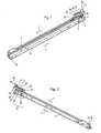
- the Rollenauszieh installation the first embodiment of two different sides is shown. It has a guide rail 3 and a second rail 8 mounted displaceably therein. These two rails 3 and 8 can be pulled apart telescopically in the withdrawal direction 1 and pushed into each other in the opposite direction of insertion 2.
- the guide rail 3 forms the carcass rail, which is usually attached to the (not shown here) furniture body.
- the second rail 8 not shown here insertable and pull-out furniture part such as a drawer is attached.
- the rails 3 and 8 are exclusively supported by rollers, here the rollers 30 and 9 to each other and slidably mounted.
- all the exemplary embodiments shown can also be modified to the effect that on the one hand more than two rails, which are telescopically movable relative to one another, are provided.
- at least one middle rail may be mounted between the guide rail 3 and the second rail 8. This is particularly favorable in what are known as full extensions, in which the movable furniture part can be completely pulled out of the furniture carcass.
- it does not necessarily have to be a pure role leadership.
- roller carriages mounted on rollers or balls, as known per se in the prior art can be integrated into the roller extension guide instead of individual rollers.
- the Disposherd Disposher 5 seen in the insertion direction 2, arranged at the rear end of the guide rail 3. It acts as explained below in more detail with a role 4 together, which, as particularly good in the 3 and 4 can be seen, is rotatably mounted on the second rail 8 by means of its roller rotation axis 9.
- This roller 4 is arranged on, as seen in the insertion direction 2, the rear end of the second rail 8 and rotatably mounted with its roller rotation axis 9.
- Good to see in the Fig. 1 and 2 also the here designed as a rotary damper damper 24, which is connected in one piece with the tilting slide 6 in the embodiment shown. The details of the tilting slide 6 will be explained below in the Fig.
- the rotary damper 24 realized here, as the first damper part 22, has a toothed wheel, which is in a Rack 29 engages the housing 25.
- the gear 22 is rotatably mounted in the, the second damper part 23 forming the housing of the damper 24.
- dampers are known per se for furniture fitting parts. They can be designed in all known in the prior art embodiments.
- the 3 and 4 now show the second rail 8 to which the movable furniture part is attached. It carries over the roller rotation axis 9.
- that roller 4 which cooperates with the tilting slide 6 and its gripper 7.
- the gripper 7 generally designates the element of the tilting slide 6, with which this acts on the roller 4 and touches it.
- this roller 4 is arranged on the rear end of the rail 8 in the insertion direction 2. Of course, this need not be so, the Edeinzugsvoruze 5 and its associated role 4 can of course also be placed further forward of the rails.
- FIGS. 5 and 6 show again separately the guide or cabinet rail 3 of this embodiment.
- Fig. 6 is particularly good to see that the guide rail 3 is seen in the direction of insertion 2 angled in its rear end portion 27, wherein, as in the Fig. 1 and 2 to see the role 4 can retract into this end portion 27.
- the gravity of the self-closing device 5 helps the roller 4 and the entire second rail 8 in their in Fig. 1 and 2 move shown end position. In this end position, the roller 4 is conveniently located on the end stop 33 in the housing 25.
- the FIGS. 5 and 6 is also good to see how the other roller 30 is seen in the direction of insertion 2 front end of the guide rail 3 is rotatably fixed by means of a corresponding roller rotation axis.
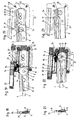
- Fig. 8 shows a section along the in Fig. 7 shown section line AA, wherein the tilting slide 6 is in its, seen in the insertion direction 2, front position in which it receives the roller 4 and engages with the gripper 7.
- Fig. 9 shows the same situation as Fig. 8 However, in a non-cut side view.
- Fig. 11 shows a sectional view along in Fig. 10 shown section line BB, here the Diseinzugsvortechnisch 5 is shown in the end position, in which the roller 4 and thus the second rail 8 is completely retracted in the direction of insertion 2.
- the roller 4 is corresponding to the end stop 33 at.
- Fig. 12 again shows a non-cut side view of this situation.
- the tilting slide 6 or its gripper 7 provided with this automatic retraction or self-closing device 5 has two gripper legs 15. These limit a recess 11 which serves to receive the roller 4.
- the gripper surface 12 is bent at least partially circular in the embodiment shown. With the gripper surface 12, the gripper 7 engages the running surface 10 of the roller 4.
- the bending radius 13 of the circular portion of the gripper surface 12 is between 100% and 110%, preferably between 100% and 105% of the Radius 14 of the tread 10 of the roller 4. It can thus, as explained above, a certain game between the roller 4 and gripper 7 may be provided without this would reduce the reliability of Diseinzugsvorraum 5.
- the tilting slide 6 has, in this embodiment, two guide pins 17 and 18 spaced from each other in the direction of withdrawal 1. With these he is forcibly guided in the guideway 20 of the housing 25.
- the guide track 20 is groove-shaped in the illustrated embodiment and is bounded by two opposite side walls 19. At its front end seen in the direction of insertion 2, the guide track 20 has an angled or bent section 21, otherwise it is conveniently linear.
- the angled portion 21 is a first, here in the insertion direction 2 front, guide pin 17 can be inserted.
- the present in this embodiment second guide pin 18 forms a pivot axis about which the tilt slide 6 pivots when the first guide pin 17 is inserted into the angled portion 21.
- the spring 31 is in the embodiment shown here, in order to realize the longest possible travel in the housing 25 doubly deflected by the spring deflection rollers 32.
- One end of the spring 31 acts on the tilting slide 6.
- the opposite end of the spring 31 is fixed to the housing 25. During the described displacement movement of the tilting slide 6 is forcibly guided over its guide pins 17 and 18 in the guideway 20.
- the damper 24 with its damper part 23 (here the damper housing) is integrally attached to the tilting slide 6.
- This causes the automatic retraction movement performed by the spring 31 to be simultaneously damped by the damper 24.
- This causes in total a gentle braking of the retraction movement, so that the roller 4, the rail 8 and the furniture part attached thereto are decelerated gently and not jerkily on reaching the end stop 33.
- a so-called malfunction protection is provided in the illustrated embodiment.
- gripper legs 15 is elastically deformable and has a direction of insertion 2 oblique contact surface 16, the roller 4 by tarnishing against the chamfer 16 and by elastically deforming the gripper arm 15 past this in the Recess 11 of the gripper 7 is slidable.
- the movement or the bending of the gripper leg 15 in this case is by the double arrow 28 in Fig. 11 illustrated.
- Fig. 13 shows the housing 25 without the guide rail 3.
- the housing 25 has a U-shaped recess 26 in which the guide rail is mounted in the illustrated embodiment with its seen in the direction of insertion 2 rear end.
- the housing 25 is favorably elastically resilient, so that it can be snapped onto the guide rail 3. With an appropriate design as a simple assembly of the housing 25 is made possible on the guide rail 3.
- FIGS. 14 to 24 show a second embodiment according to the invention a Rollenauszieh Entry. This is similar or similar in many parts to the first embodiment. However, differences exist in the type and connection of the damper 24 used and in the specific embodiment of the invention acting on the roller 4 tilting slide 6. The following description focuses on the explanation of the differences from the first embodiment. The details not explained in detail may be carried out as in the first embodiment.
- the FIGS. 14 and 15 First of all, views again point to this embodiment of the Rollenauszieh Entry from two sides.
- the second rail 8 can be made completely as in the first embodiment and is not shown again here. With respect to the rail 8 is thus on the 3 and 4 directed.
- the guide or cabinet rail 3 is without second rail 8 in the FIGS. 16 and 17 shown.
- Fig. 19 again shows the section according to Fig. 18 along the section line CC.
- Fig. 20 shows a side view of this embodiment in the position according to Fig. 19.
- Fig. 22 shows the section along the line DD in Fig. 21 , Here, the roller 4 and the second rail 8 are completely retracted.
- Fig. 23 shows the corresponding side view.
- a first difference from the first exemplary embodiment consists in that, instead of the rotary damper shown there, a linear damper 24 known per se is used. This has two relatively movable damper parts 22 and 23. 22 designates in the embodiment shown, the per se known piston rod 22 with the piston arranged thereon.
- FIGS. 19 and 20 again show the position of the tilt slide, in which he receives the roller 4 in its recess 11.
- the FIGS. 22 and 23 show the end position in which the roller 4 and the second rail 8 are completely retracted.
- the Einziehvorgang of the in the FIGS. 19 and 20 shown position in the in FIGS. 22 and 23 shown position in turn by means of the spring 31.
- the counter-movement in withdrawal 1 can be done in both embodiments, for example by hand by pulling the movable furniture part, not shown here, in turn, then by moving the tilt slide 6 in the in the FIGS. 19 and 20 shown position, the spring 31 is stretched for the next automated retraction.
- Fig. 24 the housing 25 of this embodiment is shown separately again. Again, it is U-shaped and has the recess 26 into which the guide rail 3 can be inserted. Also in this embodiment, the thus formed housing 25 is preferably snapped onto the guide rail 3.
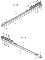
- FIGS. 25 and 26 show perspective views of the entire Rollenauszieh Adjust, wherein the second rail 8 is fully inserted in the insertion direction 2 in the guide rail 3.
- FIGS. 27 and 28 show perspective views of the second rail.
- FIGS. 29 and 30 show perspective views of the guide rail 3 with arranged thereon Diseinzugsvorraum 5, wherein the second rail 8 is removed.
- the FIGS. 31 to 33 show representations like in FIGS. 25 and 26 , but only in the rear region of the guide rail 3, in which the Edeinzugsvorraum 5 is arranged.
- Fig. 31 shows a side view
- Fig. 32 the location of the section line EE
- Fig. 33 the longitudinal section along the section line EE.
- FIGS. 34 to 36 show in otherwise to the FIGS. 31 to 33 analog representations, the situation in which the roller 4 at the beginning of the contacting during insertion in the direction of insertion 2 on the gripper 7 meets or even the situation in which when pulling in the pull-out 1 of the tilt slide 6 is already back in the first tilted or ready position is located, so the role is not 4 is held more and the second rail 8 can be further pulled in the direction of withdrawal 1.
- a first essential difference to the first two embodiments is in the third embodiment is that the housing 25 'of this embodiment has no U-shaped recess 26, but, preferably completely, seen in an operating position of the Rollenauszieh Installation, above the guide rail 3 is arranged. Of course, it can just as well, preferably completely, be arranged below the guide rail 3. Both variants have the advantage that overall the overall length of the roller extension guide is shortened, since the housing 25 'no longer projects beyond the guide rail 3 at the rear end.
- the spring 31, which provides the force for pulling in the roller 4 or the second rail 8, is no longer deflected.
- the spring 31 has an exclusively linear extension.
- the spring 31 is arranged, preferably exclusively, above the guide rail 3. Also, it is not in the insertion direction 2 on the guide rail 3 via. But just as well, the spring 31 may also, preferably exclusively, be arranged below the guide rail 3.
- the housing 25 'of the Dieinzugsvorraum 5 of this embodiment is constructed in two parts. It has a fixed to the guide rail 3 immovably fixed housing part 38. This in turn has in this embodiment, a housing rail 39 on which a connecting rod designed as a connecting element 35 is mounted relative to the fixed housing part 38, preferably parallel to the withdrawal direction 1 or insertion direction 2, slidably. As shown in particular in the sectional views. Fig. 33 and 36 can be seen, the tilting slide 6 of this embodiment is arranged on the pivot joint 34 on the connecting rod designed as a connecting body 35.
- a damper part of the damper 24 designed here as a linear damper 24 is fixed to the connecting body or the push rod 35 in the third exemplary embodiment.
- this is the damper part 23, which forms the cylinder of the damper 24.
- the piston is displaceably mounted, which is fixed to the other damper part 22 designed as a piston rod.
- the damping operation of the damper 24 takes place by sliding the damper part 23 on the piston rod or the damper part 22, at least for a part of the intake operation in the insertion direction 2.
- the damper can also be designed so that it achieves a movement-damping effect in the withdrawal direction.
- the tilting slide 6 is, as in the first embodiments, guided by means of the first guide pin 17 and the pivot pin 18 in a guide track 20, which has the angled portion 21 at its front end seen in the insertion direction 2.
- the guidance and the tilting of the tilting slide 6 by means of the guideway 2 and its angled portion 21 takes place as in the two embodiments set forth first.
- the tilting movement takes place in the pivot joint 34.
- Fig. 36 is the tilting slide 6 with its gripper 7 in the ready position or in the first tilted position.
- the roll can accumulate by corresponding insertion of the second rail 8 in the insertion direction 2 on the gripper surface 12 of the gripper 7 of the tilting slide 6.
- the gripper 7 of the tilting slide 6 engages the roller 4, in the exemplary embodiment shown, specifically at its running surface 10.
- Fig. 36 is tilted about the axis of rotation of the pivot joint 34 in its second tilted position.
- the second tilt position is z. In Fig. 33 to see.
- the first coupling part 36 is a corresponding recess in the front gripper limb 15 of the gripper 7 as viewed in the insertion direction 2.
- the second coupling part 37 is formed in the embodiment shown by a pin arranged on the second rail 8.
- the coupling parts 36 and 37 may also, unlike the exemplary embodiment shown, be arranged the other way around on tilting slide 6 and second rail 8.
- FIGS. 31 to 33 show the fully retracted position in which the roller 4 abuts the end stop 33 of the guide rail 3.
- the two coupling parts 36 and 37 are also in this position still engaged with each other. If now pulled on the second rail 8 and attached to a movable furniture part in the withdrawal direction 1, the tilting slide 6, via the coupling parts 36 and 37 directly on the second rail 8 hanging, moved in the withdrawal direction 1, so that after a through the Length of the straight portion of the guide track 20 predetermined path of the first guide pin 17 in the arranged on the fixed housing part 38 guide track 20 enters the angled section 21. By continuing the first guide pin 17 in the angled portion 21 then takes place a tilting movement of the tilting slide 6 back into the first tilted position or in the ready position gem.
Landscapes
- Engineering & Computer Science (AREA)
- Mechanical Engineering (AREA)
- Drawers Of Furniture (AREA)
Priority Applications (5)
| Application Number | Priority Date | Filing Date | Title |
|---|---|---|---|
| SI200930284T SI2174570T1 (sl) | 2008-10-07 | 2009-06-03 | Kotalno izvlečno vodilo |
| PL09007350T PL2174570T3 (pl) | 2008-10-07 | 2009-06-03 | Rolkowa prowadnica wyciągana |
| US12/588,161 US8353563B2 (en) | 2008-10-07 | 2009-10-06 | Roller extraction guide |
| AU2010201997A AU2010201997A1 (en) | 2008-10-07 | 2010-05-18 | Roller pull out guidance |
| NZ585792A NZ585792A (en) | 2008-10-07 | 2010-05-31 | Roller pull out guidance with claw engaging roller in slide-in direction |
Applications Claiming Priority (1)
| Application Number | Priority Date | Filing Date | Title |
|---|---|---|---|
| AT0156508A AT507186B1 (de) | 2008-10-07 | 2008-10-07 | Rollenausziehführung |
Publications (2)
| Publication Number | Publication Date |
|---|---|
| EP2174570A1 EP2174570A1 (de) | 2010-04-14 |
| EP2174570B1 true EP2174570B1 (de) | 2012-04-18 |
Family
ID=41558156
Family Applications (1)
| Application Number | Title | Priority Date | Filing Date |
|---|---|---|---|
| EP09007350A Active EP2174570B1 (de) | 2008-10-07 | 2009-06-03 | Rollenausziehführung |
Country Status (8)
| Country | Link |
|---|---|
| US (1) | US8353563B2 (pl) |
| EP (1) | EP2174570B1 (pl) |
| AT (2) | AT507186B1 (pl) |
| AU (1) | AU2010201997A1 (pl) |
| ES (1) | ES2386234T3 (pl) |
| NZ (1) | NZ585792A (pl) |
| PL (1) | PL2174570T3 (pl) |
| SI (1) | SI2174570T1 (pl) |
Cited By (1)
| Publication number | Priority date | Publication date | Assignee | Title |
|---|---|---|---|---|
| AT516509A4 (de) * | 2015-03-27 | 2016-06-15 | Fulterer Gmbh | Ausziehführung für aus einem Möbelkorpus herausziehbare und in diesen wieder einschiebbare Möbelteile |
Families Citing this family (5)
| Publication number | Priority date | Publication date | Assignee | Title |
|---|---|---|---|---|
| US8632141B2 (en) * | 2009-08-12 | 2014-01-21 | Segos Co., Ltd. | Sliding apparatus with self-closing means |
| IT1403268B1 (it) * | 2010-12-20 | 2013-10-17 | Muzzin S P A | Dispositivo rallentatore per guide a rulli di parti scorrevoli |
| KR20130115546A (ko) * | 2012-04-12 | 2013-10-22 | 삼성전자주식회사 | 슬라이딩 장치 및 이를 갖는 냉장고 |
| US11993196B2 (en) | 2021-10-14 | 2024-05-28 | Adrian Steel Company | Shelf system |
| USD1060020S1 (en) * | 2024-03-19 | 2025-02-04 | Changsha Baituo Import and Export Co., Ltd. | Drawer slide |
Family Cites Families (15)
| Publication number | Priority date | Publication date | Assignee | Title |
|---|---|---|---|---|
| US3104142A (en) * | 1961-06-09 | 1963-09-17 | Knape & Vogt Mfg Co | Self closing drawer slide structure |
| US4121878A (en) | 1977-04-20 | 1978-10-24 | American Hospital Supply Corporation | Cabinet drawer restrainer |
| US4447095A (en) * | 1982-06-18 | 1984-05-08 | Hardware Designers, Inc. | Self-leveling drawer slide |
| AT389218B (de) | 1983-11-25 | 1989-11-10 | Fulterer Gmbh | Schubladenauszugeinrichtung |
| US4765699A (en) * | 1987-02-06 | 1988-08-23 | Knape & Vogt Manufacturing Company | Drawer slide lift-out lock |
| DE8714720U1 (de) * | 1987-11-05 | 1987-12-17 | Ziehl, Gustav, 5000 Köln | Teleskopführung für Möbelauszüge |
| DE3818225C2 (de) * | 1988-05-28 | 1996-04-18 | Miele & Cie | Schubladenführung mit einer Rücklaufsperre |
| AT401334B (de) | 1990-07-31 | 1996-08-26 | Blum Gmbh Julius | Schliessvorrichtung für schubladen |
| AT393948B (de) | 1989-04-03 | 1992-01-10 | Blum Gmbh Julius | Schliessvorrichtung fuer schubladen |
| JPH06245831A (ja) * | 1993-02-26 | 1994-09-06 | Nhk Spring Co Ltd | 引出し用閉止装置 |
| US6848759B2 (en) * | 2002-04-03 | 2005-02-01 | Illinois Tool Works Inc. | Self-closing slide mechanism with damping |
| TW563464U (en) * | 2003-03-04 | 2003-11-21 | Nan Juen Int Co Ltd | Folding buffer device for drawer rail |
| AT413473B (de) | 2003-11-21 | 2006-03-15 | Fulterer Gmbh | Selbsteinzugvorrichtung |
| US6902244B1 (en) * | 2003-12-15 | 2005-06-07 | Protrend Co., Ltd. | Drawer rail structure allowing adjusting of vertical position of drawer front panel |
| US8632141B2 (en) * | 2009-08-12 | 2014-01-21 | Segos Co., Ltd. | Sliding apparatus with self-closing means |
-
2008
- 2008-10-07 AT AT0156508A patent/AT507186B1/de not_active IP Right Cessation
-
2009
- 2009-06-03 PL PL09007350T patent/PL2174570T3/pl unknown
- 2009-06-03 SI SI200930284T patent/SI2174570T1/sl unknown
- 2009-06-03 EP EP09007350A patent/EP2174570B1/de active Active
- 2009-06-03 AT AT09007350T patent/ATE553672T1/de active
- 2009-06-03 ES ES09007350T patent/ES2386234T3/es active Active
- 2009-10-06 US US12/588,161 patent/US8353563B2/en active Active
-
2010
- 2010-05-18 AU AU2010201997A patent/AU2010201997A1/en not_active Abandoned
- 2010-05-31 NZ NZ585792A patent/NZ585792A/en not_active IP Right Cessation
Cited By (1)
| Publication number | Priority date | Publication date | Assignee | Title |
|---|---|---|---|---|
| AT516509A4 (de) * | 2015-03-27 | 2016-06-15 | Fulterer Gmbh | Ausziehführung für aus einem Möbelkorpus herausziehbare und in diesen wieder einschiebbare Möbelteile |
Also Published As
| Publication number | Publication date |
|---|---|
| US20100086244A1 (en) | 2010-04-08 |
| US8353563B2 (en) | 2013-01-15 |
| AT507186A4 (de) | 2010-03-15 |
| PL2174570T3 (pl) | 2012-09-28 |
| AU2010201997A1 (en) | 2010-12-23 |
| EP2174570A1 (de) | 2010-04-14 |
| NZ585792A (en) | 2011-09-30 |
| SI2174570T1 (sl) | 2012-08-31 |
| AT507186B1 (de) | 2010-03-15 |
| ES2386234T3 (es) | 2012-08-14 |
| ATE553672T1 (de) | 2012-05-15 |
Similar Documents
| Publication | Publication Date | Title |
|---|---|---|
| AT509923B1 (de) | Einzugsvorrichtung zum einziehen eines bewegbar gelagerten möbelteiles | |
| EP3307975B1 (de) | Ausstossvorrichtung für ein bewegbares möbelteil | |
| EP3518707B1 (de) | Einzugsvorrichtung für einen schubladenauszug | |
| EP1658785B1 (de) | Einzugshilfe für einen Auszug | |
| AT506062B1 (de) | Rollen-ausziehführung | |
| EP2807320B1 (de) | Ausziehvorrichtung für mindestens zwei ausziehbare möbelteile | |
| EP1972229B1 (de) | Schrank | |
| DE112006000842B4 (de) | Gleitschieneneinheit mit Haltefunktion | |
| WO2013138826A1 (de) | Zuziehvorrichtung für ein beweglich gelagertes möbelteil | |
| AT507186B1 (de) | Rollenausziehführung | |
| EP1374733A1 (de) | Schubladenführung | |
| DE102011051907A1 (de) | Einzugsvorrichtung für bewegbare Möbelteile | |
| EP2956032A1 (de) | Auszugsführung für ein bewegbares möbelteil | |
| EP2730734A2 (de) | Bidirektionale Einzugsvorrichtung für eine mittlere Schiebetür | |
| EP2464258B1 (de) | Ein- oder auszugsvorrichtung zum bewegen eines bewegbaren möbelteiles | |
| EP4164450B1 (de) | Selbsteinziehvorrichtung | |
| EP2806769B1 (de) | Einziehsystem für mehrere ausziehbare möbelteile | |
| WO2008012038A2 (de) | Ausziehführung zur führung von möbelteilen | |
| DE29701895U1 (de) | Vorrichtung zum Einziehen und lösbaren Halten von Führungsschienen | |
| AT410508B (de) | Bremseinrichtung zum abbremsen der einfahr- oder ausziehbewegung eines ausziehbaren möbelteils | |
| DE102024117471B3 (de) | Differentialauszug mit Selbsteinzugsvorrichtung | |
| AT523706A4 (de) | Selbsteinziehvorrichtung für ein ausziehbares Möbelteil | |
| DE29805930U1 (de) | Ausziehführung | |
| DE202011104526U1 (de) | Vorrichtung zur Bewegung eines bewegbaren Möbelteils, Führungseinheit und Möbel | |
| EP3072417B1 (de) | Ausziehführung für aus einem möbelkorpus herausziehbare und in diesen wieder einschiebbare möbelteile |
Legal Events
| Date | Code | Title | Description |
|---|---|---|---|
| PUAI | Public reference made under article 153(3) epc to a published international application that has entered the european phase |
Free format text: ORIGINAL CODE: 0009012 |
|
| AK | Designated contracting states |
Kind code of ref document: A1 Designated state(s): AT BE BG CH CY CZ DE DK EE ES FI FR GB GR HR HU IE IS IT LI LT LU LV MC MK MT NL NO PL PT RO SE SI SK TR |
|
| AX | Request for extension of the european patent |
Extension state: AL BA RS |
|
| 17P | Request for examination filed |
Effective date: 20101004 |
|
| GRAP | Despatch of communication of intention to grant a patent |
Free format text: ORIGINAL CODE: EPIDOSNIGR1 |
|
| GRAS | Grant fee paid |
Free format text: ORIGINAL CODE: EPIDOSNIGR3 |
|
| GRAA | (expected) grant |
Free format text: ORIGINAL CODE: 0009210 |
|
| AK | Designated contracting states |
Kind code of ref document: B1 Designated state(s): AT BE BG CH CY CZ DE DK EE ES FI FR GB GR HR HU IE IS IT LI LT LU LV MC MK MT NL NO PL PT RO SE SI SK TR |
|
| RAP1 | Party data changed (applicant data changed or rights of an application transferred) |
Owner name: FULTERER GESELLSCHAFT MBH |
|
| REG | Reference to a national code |
Ref country code: GB Ref legal event code: FG4D Free format text: NOT ENGLISH |
|
| REG | Reference to a national code |
Ref country code: CH Ref legal event code: EP |
|
| REG | Reference to a national code |
Ref country code: IE Ref legal event code: FG4D Free format text: LANGUAGE OF EP DOCUMENT: GERMAN |
|
| REG | Reference to a national code |
Ref country code: AT Ref legal event code: REF Ref document number: 553672 Country of ref document: AT Kind code of ref document: T Effective date: 20120515 Ref country code: CH Ref legal event code: NV Representative=s name: LUCHS & PARTNER AG PATENTANWAELTE |
|
| REG | Reference to a national code |
Ref country code: DE Ref legal event code: R096 Ref document number: 502009003247 Country of ref document: DE Effective date: 20120614 |
|
| REG | Reference to a national code |
Ref country code: NL Ref legal event code: T3 |
|
| PGFP | Annual fee paid to national office [announced via postgrant information from national office to epo] |
Ref country code: TR Payment date: 20120528 Year of fee payment: 4 Ref country code: NL Payment date: 20120629 Year of fee payment: 4 Ref country code: SK Payment date: 20120530 Year of fee payment: 4 |
|
| REG | Reference to a national code |
Ref country code: SK Ref legal event code: T3 Ref document number: E 11843 Country of ref document: SK |
|
| REG | Reference to a national code |
Ref country code: SE Ref legal event code: TRGR |
|
| REG | Reference to a national code |
Ref country code: ES Ref legal event code: FG2A Ref document number: 2386234 Country of ref document: ES Kind code of ref document: T3 Effective date: 20120814 |
|
| LTIE | Lt: invalidation of european patent or patent extension |
Effective date: 20120418 |
|
| REG | Reference to a national code |
Ref country code: PL Ref legal event code: T3 |
|
| PG25 | Lapsed in a contracting state [announced via postgrant information from national office to epo] |
Ref country code: NO Free format text: LAPSE BECAUSE OF FAILURE TO SUBMIT A TRANSLATION OF THE DESCRIPTION OR TO PAY THE FEE WITHIN THE PRESCRIBED TIME-LIMIT Effective date: 20120718 Ref country code: IS Free format text: LAPSE BECAUSE OF FAILURE TO SUBMIT A TRANSLATION OF THE DESCRIPTION OR TO PAY THE FEE WITHIN THE PRESCRIBED TIME-LIMIT Effective date: 20120818 Ref country code: FI Free format text: LAPSE BECAUSE OF FAILURE TO SUBMIT A TRANSLATION OF THE DESCRIPTION OR TO PAY THE FEE WITHIN THE PRESCRIBED TIME-LIMIT Effective date: 20120418 Ref country code: CY Free format text: LAPSE BECAUSE OF FAILURE TO SUBMIT A TRANSLATION OF THE DESCRIPTION OR TO PAY THE FEE WITHIN THE PRESCRIBED TIME-LIMIT Effective date: 20120418 Ref country code: LT Free format text: LAPSE BECAUSE OF FAILURE TO SUBMIT A TRANSLATION OF THE DESCRIPTION OR TO PAY THE FEE WITHIN THE PRESCRIBED TIME-LIMIT Effective date: 20120418 |
|
| PGFP | Annual fee paid to national office [announced via postgrant information from national office to epo] |
Ref country code: SE Payment date: 20120629 Year of fee payment: 4 |
|
| PG25 | Lapsed in a contracting state [announced via postgrant information from national office to epo] |
Ref country code: PT Free format text: LAPSE BECAUSE OF FAILURE TO SUBMIT A TRANSLATION OF THE DESCRIPTION OR TO PAY THE FEE WITHIN THE PRESCRIBED TIME-LIMIT Effective date: 20120820 Ref country code: HR Free format text: LAPSE BECAUSE OF FAILURE TO SUBMIT A TRANSLATION OF THE DESCRIPTION OR TO PAY THE FEE WITHIN THE PRESCRIBED TIME-LIMIT Effective date: 20120418 Ref country code: GR Free format text: LAPSE BECAUSE OF FAILURE TO SUBMIT A TRANSLATION OF THE DESCRIPTION OR TO PAY THE FEE WITHIN THE PRESCRIBED TIME-LIMIT Effective date: 20120719 Ref country code: LV Free format text: LAPSE BECAUSE OF FAILURE TO SUBMIT A TRANSLATION OF THE DESCRIPTION OR TO PAY THE FEE WITHIN THE PRESCRIBED TIME-LIMIT Effective date: 20120418 |
|
| PGFP | Annual fee paid to national office [announced via postgrant information from national office to epo] |
Ref country code: PL Payment date: 20120529 Year of fee payment: 4 Ref country code: SI Payment date: 20120604 Year of fee payment: 4 |
|
| PGFP | Annual fee paid to national office [announced via postgrant information from national office to epo] |
Ref country code: BE Payment date: 20120726 Year of fee payment: 4 Ref country code: FR Payment date: 20120720 Year of fee payment: 4 |
|
| PG25 | Lapsed in a contracting state [announced via postgrant information from national office to epo] |
Ref country code: RO Free format text: LAPSE BECAUSE OF FAILURE TO SUBMIT A TRANSLATION OF THE DESCRIPTION OR TO PAY THE FEE WITHIN THE PRESCRIBED TIME-LIMIT Effective date: 20120418 Ref country code: DK Free format text: LAPSE BECAUSE OF FAILURE TO SUBMIT A TRANSLATION OF THE DESCRIPTION OR TO PAY THE FEE WITHIN THE PRESCRIBED TIME-LIMIT Effective date: 20120418 Ref country code: EE Free format text: LAPSE BECAUSE OF FAILURE TO SUBMIT A TRANSLATION OF THE DESCRIPTION OR TO PAY THE FEE WITHIN THE PRESCRIBED TIME-LIMIT Effective date: 20120418 Ref country code: MC Free format text: LAPSE BECAUSE OF NON-PAYMENT OF DUE FEES Effective date: 20120630 |
|
| PLBE | No opposition filed within time limit |
Free format text: ORIGINAL CODE: 0009261 |
|
| STAA | Information on the status of an ep patent application or granted ep patent |
Free format text: STATUS: NO OPPOSITION FILED WITHIN TIME LIMIT |
|
| PG25 | Lapsed in a contracting state [announced via postgrant information from national office to epo] |
Ref country code: MK Free format text: LAPSE BECAUSE OF FAILURE TO SUBMIT A TRANSLATION OF THE DESCRIPTION OR TO PAY THE FEE WITHIN THE PRESCRIBED TIME-LIMIT Effective date: 20120418 |
|
| 26N | No opposition filed |
Effective date: 20130121 |
|
| REG | Reference to a national code |
Ref country code: IE Ref legal event code: MM4A |
|
| PG25 | Lapsed in a contracting state [announced via postgrant information from national office to epo] |
Ref country code: IE Free format text: LAPSE BECAUSE OF NON-PAYMENT OF DUE FEES Effective date: 20120603 |
|
| REG | Reference to a national code |
Ref country code: DE Ref legal event code: R097 Ref document number: 502009003247 Country of ref document: DE Effective date: 20130121 |
|
| PG25 | Lapsed in a contracting state [announced via postgrant information from national office to epo] |
Ref country code: BG Free format text: LAPSE BECAUSE OF FAILURE TO SUBMIT A TRANSLATION OF THE DESCRIPTION OR TO PAY THE FEE WITHIN THE PRESCRIBED TIME-LIMIT Effective date: 20120718 Ref country code: MT Free format text: LAPSE BECAUSE OF FAILURE TO SUBMIT A TRANSLATION OF THE DESCRIPTION OR TO PAY THE FEE WITHIN THE PRESCRIBED TIME-LIMIT Effective date: 20120418 |
|
| BERE | Be: lapsed |
Owner name: FULTERER -G. MBH Effective date: 20130630 |
|
| REG | Reference to a national code |
Ref country code: NL Ref legal event code: V1 Effective date: 20140101 |
|
| PG25 | Lapsed in a contracting state [announced via postgrant information from national office to epo] |
Ref country code: SE Free format text: LAPSE BECAUSE OF NON-PAYMENT OF DUE FEES Effective date: 20130604 Ref country code: CZ Free format text: LAPSE BECAUSE OF NON-PAYMENT OF DUE FEES Effective date: 20130603 |
|
| REG | Reference to a national code |
Ref country code: SE Ref legal event code: EUG |
|
| GBPC | Gb: european patent ceased through non-payment of renewal fee |
Effective date: 20130603 |
|
| REG | Reference to a national code |
Ref country code: SK Ref legal event code: MM4A Ref document number: E 11843 Country of ref document: SK Effective date: 20130603 |
|
| REG | Reference to a national code |
Ref country code: FR Ref legal event code: ST Effective date: 20140228 |
|
| PG25 | Lapsed in a contracting state [announced via postgrant information from national office to epo] |
Ref country code: BE Free format text: LAPSE BECAUSE OF NON-PAYMENT OF DUE FEES Effective date: 20130630 |
|
| REG | Reference to a national code |
Ref country code: SI Ref legal event code: KO00 Effective date: 20140225 |
|
| PG25 | Lapsed in a contracting state [announced via postgrant information from national office to epo] |
Ref country code: NL Free format text: LAPSE BECAUSE OF NON-PAYMENT OF DUE FEES Effective date: 20140101 Ref country code: GB Free format text: LAPSE BECAUSE OF NON-PAYMENT OF DUE FEES Effective date: 20130603 Ref country code: SK Free format text: LAPSE BECAUSE OF NON-PAYMENT OF DUE FEES Effective date: 20130603 |
|
| PG25 | Lapsed in a contracting state [announced via postgrant information from national office to epo] |
Ref country code: SI Free format text: LAPSE BECAUSE OF NON-PAYMENT OF DUE FEES Effective date: 20130604 Ref country code: FR Free format text: LAPSE BECAUSE OF NON-PAYMENT OF DUE FEES Effective date: 20130701 Ref country code: LU Free format text: LAPSE BECAUSE OF NON-PAYMENT OF DUE FEES Effective date: 20120603 |
|
| PG25 | Lapsed in a contracting state [announced via postgrant information from national office to epo] |
Ref country code: HU Free format text: LAPSE BECAUSE OF FAILURE TO SUBMIT A TRANSLATION OF THE DESCRIPTION OR TO PAY THE FEE WITHIN THE PRESCRIBED TIME-LIMIT Effective date: 20090603 |
|
| REG | Reference to a national code |
Ref country code: PL Ref legal event code: LAPE |
|
| PG25 | Lapsed in a contracting state [announced via postgrant information from national office to epo] |
Ref country code: PL Free format text: LAPSE BECAUSE OF NON-PAYMENT OF DUE FEES Effective date: 20130603 |
|
| PG25 | Lapsed in a contracting state [announced via postgrant information from national office to epo] |
Ref country code: TR Free format text: LAPSE BECAUSE OF NON-PAYMENT OF DUE FEES Effective date: 20130603 |
|
| REG | Reference to a national code |
Ref country code: DE Ref legal event code: R079 Ref document number: 502009003247 Country of ref document: DE Free format text: PREVIOUS MAIN CLASS: A47B0088040000 Ipc: A47B0088400000 |
|
| REG | Reference to a national code |
Ref country code: DE Ref legal event code: R082 Ref document number: 502009003247 Country of ref document: DE Representative=s name: VKK PATENTANWAELTE PARTG MBB, DE |
|
| P01 | Opt-out of the competence of the unified patent court (upc) registered |
Effective date: 20230514 |
|
| PGFP | Annual fee paid to national office [announced via postgrant information from national office to epo] |
Ref country code: DE Payment date: 20250618 Year of fee payment: 17 |
|
| PGFP | Annual fee paid to national office [announced via postgrant information from national office to epo] |
Ref country code: AT Payment date: 20250616 Year of fee payment: 17 |
|
| PGFP | Annual fee paid to national office [announced via postgrant information from national office to epo] |
Ref country code: ES Payment date: 20250718 Year of fee payment: 17 |
|
| PGFP | Annual fee paid to national office [announced via postgrant information from national office to epo] |
Ref country code: IT Payment date: 20250630 Year of fee payment: 17 |
|
| PGFP | Annual fee paid to national office [announced via postgrant information from national office to epo] |
Ref country code: CH Payment date: 20250701 Year of fee payment: 17 |