EP2173981B1 - Sicherbares montagematerial sowie verfahren zu seiner herstellung und verwendung - Google Patents
Sicherbares montagematerial sowie verfahren zu seiner herstellung und verwendung Download PDFInfo
- Publication number
- EP2173981B1 EP2173981B1 EP08795823.7A EP08795823A EP2173981B1 EP 2173981 B1 EP2173981 B1 EP 2173981B1 EP 08795823 A EP08795823 A EP 08795823A EP 2173981 B1 EP2173981 B1 EP 2173981B1
- Authority
- EP
- European Patent Office
- Prior art keywords
- mounting material
- securable
- activatable adhesive
- thermally activatable
- housing
- Prior art date
- Legal status (The legal status is an assumption and is not a legal conclusion. Google has not performed a legal analysis and makes no representation as to the accuracy of the status listed.)
- Active
Links
Images

Classifications
-
- F—MECHANICAL ENGINEERING; LIGHTING; HEATING; WEAPONS; BLASTING
- F01—MACHINES OR ENGINES IN GENERAL; ENGINE PLANTS IN GENERAL; STEAM ENGINES
- F01N—GAS-FLOW SILENCERS OR EXHAUST APPARATUS FOR MACHINES OR ENGINES IN GENERAL; GAS-FLOW SILENCERS OR EXHAUST APPARATUS FOR INTERNAL COMBUSTION ENGINES
- F01N3/00—Exhaust or silencing apparatus having means for purifying, rendering innocuous, or otherwise treating exhaust
- F01N3/08—Exhaust or silencing apparatus having means for purifying, rendering innocuous, or otherwise treating exhaust for rendering innocuous
- F01N3/10—Exhaust or silencing apparatus having means for purifying, rendering innocuous, or otherwise treating exhaust for rendering innocuous by thermal or catalytic conversion of noxious components of exhaust
- F01N3/24—Exhaust or silencing apparatus having means for purifying, rendering innocuous, or otherwise treating exhaust for rendering innocuous by thermal or catalytic conversion of noxious components of exhaust characterised by constructional aspects of converting apparatus
- F01N3/28—Construction of catalytic reactors
- F01N3/2839—Arrangements for mounting catalyst support in housing, e.g. with means for compensating thermal expansion or vibration
- F01N3/2853—Arrangements for mounting catalyst support in housing, e.g. with means for compensating thermal expansion or vibration using mats or gaskets between catalyst body and housing
-
- F—MECHANICAL ENGINEERING; LIGHTING; HEATING; WEAPONS; BLASTING
- F01—MACHINES OR ENGINES IN GENERAL; ENGINE PLANTS IN GENERAL; STEAM ENGINES
- F01N—GAS-FLOW SILENCERS OR EXHAUST APPARATUS FOR MACHINES OR ENGINES IN GENERAL; GAS-FLOW SILENCERS OR EXHAUST APPARATUS FOR INTERNAL COMBUSTION ENGINES
- F01N3/00—Exhaust or silencing apparatus having means for purifying, rendering innocuous, or otherwise treating exhaust
- F01N3/02—Exhaust or silencing apparatus having means for purifying, rendering innocuous, or otherwise treating exhaust for cooling, or for removing solid constituents of, exhaust
- F01N3/021—Exhaust or silencing apparatus having means for purifying, rendering innocuous, or otherwise treating exhaust for cooling, or for removing solid constituents of, exhaust by means of filters
- F01N3/0211—Arrangements for mounting filtering elements in housing, e.g. with means for compensating thermal expansion or vibration
-
- F—MECHANICAL ENGINEERING; LIGHTING; HEATING; WEAPONS; BLASTING
- F01—MACHINES OR ENGINES IN GENERAL; ENGINE PLANTS IN GENERAL; STEAM ENGINES
- F01N—GAS-FLOW SILENCERS OR EXHAUST APPARATUS FOR MACHINES OR ENGINES IN GENERAL; GAS-FLOW SILENCERS OR EXHAUST APPARATUS FOR INTERNAL COMBUSTION ENGINES
- F01N3/00—Exhaust or silencing apparatus having means for purifying, rendering innocuous, or otherwise treating exhaust
- F01N3/08—Exhaust or silencing apparatus having means for purifying, rendering innocuous, or otherwise treating exhaust for rendering innocuous
- F01N3/10—Exhaust or silencing apparatus having means for purifying, rendering innocuous, or otherwise treating exhaust for rendering innocuous by thermal or catalytic conversion of noxious components of exhaust
- F01N3/24—Exhaust or silencing apparatus having means for purifying, rendering innocuous, or otherwise treating exhaust for rendering innocuous by thermal or catalytic conversion of noxious components of exhaust characterised by constructional aspects of converting apparatus
- F01N3/28—Construction of catalytic reactors
- F01N3/2839—Arrangements for mounting catalyst support in housing, e.g. with means for compensating thermal expansion or vibration
- F01N3/2853—Arrangements for mounting catalyst support in housing, e.g. with means for compensating thermal expansion or vibration using mats or gaskets between catalyst body and housing
- F01N3/2864—Arrangements for mounting catalyst support in housing, e.g. with means for compensating thermal expansion or vibration using mats or gaskets between catalyst body and housing the mats or gaskets comprising two or more insulation layers
-
- F—MECHANICAL ENGINEERING; LIGHTING; HEATING; WEAPONS; BLASTING
- F01—MACHINES OR ENGINES IN GENERAL; ENGINE PLANTS IN GENERAL; STEAM ENGINES
- F01N—GAS-FLOW SILENCERS OR EXHAUST APPARATUS FOR MACHINES OR ENGINES IN GENERAL; GAS-FLOW SILENCERS OR EXHAUST APPARATUS FOR INTERNAL COMBUSTION ENGINES
- F01N2350/00—Arrangements for fitting catalyst support or particle filter element in the housing
- F01N2350/02—Fitting ceramic monoliths in a metallic housing
- F01N2350/04—Fitting ceramic monoliths in a metallic housing with means compensating thermal expansion
-
- Y—GENERAL TAGGING OF NEW TECHNOLOGICAL DEVELOPMENTS; GENERAL TAGGING OF CROSS-SECTIONAL TECHNOLOGIES SPANNING OVER SEVERAL SECTIONS OF THE IPC; TECHNICAL SUBJECTS COVERED BY FORMER USPC CROSS-REFERENCE ART COLLECTIONS [XRACs] AND DIGESTS
- Y02—TECHNOLOGIES OR APPLICATIONS FOR MITIGATION OR ADAPTATION AGAINST CLIMATE CHANGE
- Y02T—CLIMATE CHANGE MITIGATION TECHNOLOGIES RELATED TO TRANSPORTATION
- Y02T10/00—Road transport of goods or passengers
- Y02T10/10—Internal combustion engine [ICE] based vehicles
- Y02T10/12—Improving ICE efficiencies
-
- Y—GENERAL TAGGING OF NEW TECHNOLOGICAL DEVELOPMENTS; GENERAL TAGGING OF CROSS-SECTIONAL TECHNOLOGIES SPANNING OVER SEVERAL SECTIONS OF THE IPC; TECHNICAL SUBJECTS COVERED BY FORMER USPC CROSS-REFERENCE ART COLLECTIONS [XRACs] AND DIGESTS
- Y10—TECHNICAL SUBJECTS COVERED BY FORMER USPC
- Y10T—TECHNICAL SUBJECTS COVERED BY FORMER US CLASSIFICATION
- Y10T428/00—Stock material or miscellaneous articles
- Y10T428/249921—Web or sheet containing structurally defined element or component
-
- Y—GENERAL TAGGING OF NEW TECHNOLOGICAL DEVELOPMENTS; GENERAL TAGGING OF CROSS-SECTIONAL TECHNOLOGIES SPANNING OVER SEVERAL SECTIONS OF THE IPC; TECHNICAL SUBJECTS COVERED BY FORMER USPC CROSS-REFERENCE ART COLLECTIONS [XRACs] AND DIGESTS
- Y10—TECHNICAL SUBJECTS COVERED BY FORMER USPC
- Y10T—TECHNICAL SUBJECTS COVERED BY FORMER US CLASSIFICATION
- Y10T428/00—Stock material or miscellaneous articles
- Y10T428/26—Web or sheet containing structurally defined element or component, the element or component having a specified physical dimension
Definitions
- Catalytic converters contain a catalyst, which is typically coated onto a monolithic structure mounted in the converter.
- the monolithic structures are typically ceramic, although metal monoliths have been used.
- the catalyst oxidizes carbon monoxide and hydrocarbons, and reduces the oxides of nitrogen in automobile exhaust gases to control atmospheric pollution.
- Diesel particulate filters or traps are generally wall flow filters which have honeycombed monolithic structures (also termed “monoliths”), typically made from porous crystalline ceramic material.
- each type of these devices has a metal housing which holds within it a monolithic structure or element that can be metal or ceramic, and is most commonly ceramic.
- the ceramic monolith generally has very thin walls to provide a large amount of surface area and is fragile and susceptible to breakage.
- ceramic monoliths used in automotive catalytic converters toward monoliths having smoother outer surfaces that makes it more difficult to maintain adhesion of the mounting material to the ceramic monolith during canning.
- Ceramic monoliths also typically have coefficients of thermal expansion that are an order of magnitude less than typical metal housings (for example, stainless steel housings) in which they would be contained in use.
- US 6,967,006 discloses a method for mounting and insulating ceramic monoliths in an automobile exhaust system, in which a specific bearing mat is employed.
- US 2004/057879 discloses a thermal insulating material comprising a thermal insulating material body formed of a bulk material of inorganic fibers; and a coating provided on at least one surface of said thermal insulating material body.
- WO 97/48890 discloses a pollution control device for purifying exhaust gas from an internal combustion engine, the pollution control device comprising a metallic housing; a pollution control element disposed within the housing; a metallic end cone for connecting the housing to an exhaust pipe of an internal combustion engine; and an insulating cone having an inner surface and an outer surface, the insulating cone positioned within the metallic end cone, such that a substantial portion of the inner surface of the insulating cone is exposed to hot exhaust gas from the internal combustion engine.
- WO 2004/064996 discloses an article comprising a molded three-dimensional insulator having dimensions suitable for use in an end cone region of a pollution control device, said insulator comprising ceramic fibers having a bulk shrinkage no greater than 10 percent using the Thermal Mechanical Analyzer test, wherein said insulator is self-supporting, seamless, and has a compressibility value no greater than 750 kN/m 2 when the mount density is about 0.4 g/ml.
- the present invention provides a securable mounting material comprising:
- the layer of a thermally activatable adhesive does not contact the second major surface.
- the term "flexible” means capable of passing the Flexibility Test included hereinbelow; the term “layer” excludes anything that extends throughout the entire mounting material; and the superscript term “+” refers to positive charge, while the superscript term “-” refers to negative charge. In the case where d is zero, then n is necessarily zero and the quantity (Z p O q (OH) r ) will have no net charge.
- Securable mounting material according to the present invention may be adapted for use in a pollution control device.
- the present invention provides a pollution control device comprising: a housing; a pollution control element disposed within the housing; and the securable mounting material according to the present invention disposed adjacent to, or within, the housing.
- the present invention provides a method of making a pollution control device, the method comprising: disposing a securable mounting material according to the present invention adjacent to, or within, a housing having a pollution control element disposed within the housing.
- the securable mounting material is disposed between the pollution control element and the housing.
- the present invention provides a method of making a securable mounting material, the method comprising:
- said at least one compound is selected from the group consisting of boric acid, borate salts, phosphoric acid, phosphate salts, hydrates of the foregoing, and combinations thereof.
- each M m+ is independently selected from the group consisting of metal cations and NR 4 + wherein each R independently represents H or an alkyl group.
- the thermally activatable adhesive is essentially free of organic components.
- at least a portion of the inorganic fibers are bonded together by a binder.
- the binder comprises organic material.
- the mounting material has a dry basis weight of from 0.4 to 15 kilograms per square meter.
- the mounting material further comprises an unexpanded intumescent material.
- the unexpanded intumescent material comprises vermiculite, graphite, or a combination thereof.
- the inorganic fibers comprise ceramic fibers.
- the layer of thermally activatable adhesive has an inward thickness of less than or equal to 0.3 centimeter. In certain embodiments, the layer of thermally activatable adhesive is inwardly disposed on the inorganic fibers proximate the major surface.
- the method further comprises adapting the securable mounting material for use in a pollution control device.
- Securable mounting material according to the present invention is first of all flexible, which enables it to be wound around a typical monolith without fracture or breakage. Further, when used in pollution control devices such as those described hereinabove, the securable mounting material may be secured to the housing and/or monolith by heated exhaust gas thereby preventing slippage relative to the housing and/or monolith and maintaining a tight seal to the housing and/or monolith. By preventing slippage, it is typically possible to use less mounting material than is current practice in the art.
- dryable means that any liquid vehicle present may be at least substantially removed by evaporation.
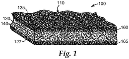
- FIG. 1 shows an exemplary securable mounting material 100 according to the present invention.
- mounting material 110 has inorganic fibers 140, optionally bonded together by a binder (not shown), and optional unexpanded intumescent particles 130.
- Mounting material 110 has first and second major surfaces 125, 127.
- Layer of thermally activatable adhesive 160 is inwardly disposed on the inorganic fibers 140 proximate first major surface 125, but does not extend throughout the entirety of mounting material 110; for example, it does not contact second major surface 127.
- a second, optional, layer of thermally activatable adhesive 165 which may have the same or different composition as layer of thermally activatable adhesive 160, is inwardly disposed on the inorganic fibers 140 proximate second major surface 127, but does not contact first major surface 125.
- the mounting material comprises inorganic fibers that are sufficiently entangled and/or bonded together to form a cohesive web.
- the fibers may be entangled by a mechanical process (for example, needletacking or hydroentangling) and/or bonded together using a binder (for example, organic binder, inorganic binder, or a combination thereof).
- a binder for example, organic binder, inorganic binder, or a combination thereof.
- the mounting material may also include organic fibers, although typically included in minor amounts, if at all.
- Useful inorganic fibers include for example, fiberglass, ceramic fibers, non-oxide inorganic fibers such as stainless steel fibers or boron fibers, and mixtures thereof.
- Useful ceramic fibers include, for example, aluminoborosilicate fibers, aluminosilicate fibers, alumina fibers, heat-treated versions thereof, and mixtures thereof.
- suitable aluminoborosilicate fibers include those commercially available under the trade designations "NEXTEL 312 CERAMIC FIBERS", “NEXTEL 440 CERAMIC FIBERS”, and “NEXTEL 550 CERAMIC FIBERS” from 3M Company, St. Paul, Minnesota.
- aluminosilicate fibers examples include those available under the trade designations "FIBERFRAX” 7000M from Unifrax Corp., Niagara Falls, New York, “CERAFIBER” from Thermal Ceramics, Augusta, Georgia; and "SNSC Type 1260 D1" from Nippon Steel Chemical Company, Tokyo, Japan.
- suitable commercially available alumina fibers include polycrystalline alumina fibers available from Saffil, Widnes, England under the trade designation "SAFFIL”.
- SAFFIL trade designation
- Suitable ceramic fibers are also disclosed in U. S. Pat. Nos. 3,795,524 (Sowman ) and 4,047,965 (Karst et al. ).
- suitable inorganic fibers include: quartz fibers, amorphous and crystalline fibers of high silica content, alumina fibers and high alumina fibers, amorphous and crystalline alumina-silica fibers, oxide and non-oxide fibers, metallic fibers, fibers formed by blowing, spinning and pulling from a melt, sol-gel formed fibers, fibers formed from organic precursors, glass fibers, leached glass fibers, and other fibers of a substantially inorganic composition.
- Suitable inorganic fibers may also comprise a surface coating or a sizing of organic and inorganic material. Suitable inorganic fibers may obviously be used alone or in combination with other suitable inorganic fibers.
- the mounting material may contain less than 50, 30, or even less than 15 percent by weight, or less, of shot based on the total dry weight of the mounting material.
- Suitable organic binders for the mounting material are known in the art and include polymers and elastomers in the latex form (for example, natural rubber latexes, styrenebutadiene latexes, butadiene-acrylonitrile latexes, and latexes of acrylate and methacrylate polymers and copolymers).
- organic binders are flocculated onto the fibers of the web using a flocculating agent, especially during wet laid manufacturing processes.
- Suitable inorganic binders are known in the art for such use and include tetrasilisic fluorine mica, in either the water-swelling unexchanged form or after flocculation as the exchanged salt with a divalent or polyvalent cation, and bentonite.
- the mounting material may comprise one or more intumescent materials (which may be unexpanded, partially expanded, expanded, or a mixture thereof), typically, depending on the desired end use.
- intumescent materials which may be unexpanded, partially expanded, expanded, or a mixture thereof
- intumescent materials typically, depending on the desired end use.
- unexpanded vermiculite materials are suitable since they start to expand at a temperature range of from about 300 °C to about 340 °C. This may be useful to fill the expanding gap between an expanding metal housing and a monolith in a catalytic converter.
- expandable graphite or a mixture of expandable graphite and unexpanded vermiculite materials may be desired since expandable graphite starts to expand or intumesce at about 210 °C.
- Treated vermiculites are also useful and typically expand at a temperature of about 290 °C.
- useful intumescent materials include unexpanded vermiculite flakes or ore, treated unexpanded vermiculite flakes or ore, partially dehydrated vermiculite ore, expandable graphite, mixtures of expandable graphite with treated or untreated unexpanded vermiculite ore, hydrobiotite, water swellable synthetic tetrasilicic fluorine type mica (for example, as described in U. S. Pat. No. 3,001,571 (Hatch )), alkali metal silicate granules (for example, as described in U. S. Pat. No. 4,521,333 (Graham et al.
- processed expandable sodium silicate for example, insoluble sodium silicate commercially available under the trade designation "EXPANTROL” from 3M Company
- expanded expandable graphite material is that available under the trade designation "GRAFOIL Grade 338-50" expandable graphite flake, from UCAR Carbon Co., Cleveland, Ohio.
- Treated unexpanded vermiculite flakes or ore includes unexpanded vermiculite treated by processes such as by being ion exchanged with ion exchange salts such as ammonium dihydrogen phosphate, ammonium nitrate, ammonium chloride, potassium chloride, or other suitable compounds as is known in the art.
- Factors to consider in choosing an intumescent sheet material typically include the use temperature and the type of monolith (for example, ceramic monolith or metallic monolith).
- Suitable intumescent sheet materials typically comprise unexpanded vermiculite ore (commercially available, for example, from W. R. Grace and Co., Cambridge, MA), organic binder and/or inorganic binder, ceramic fibers, and filler (for example, clay (for example, kaolin) and hollow ceramic beads or bubbles).
- U. S. Pat. No. 3,916,057 discloses intumescent sheet material comprising unexpanded vermiculite, inorganic fibrous material, and inorganic binder.
- intumescent sheet material comprising ammonium ion-treated vermiculite, inorganic fibrous material, and organic binder. Further, intumescent sheet material is commercially available, for example, from the 3M Company of St. Paul, MN, under the trade designation "INTERAM MAT MOUNT.”
- the mounting material comprises, on a dry weight basis, from 30 to 99.5 percent by weight of the inorganic fibers (for example, from 40 to 98.5 percent by weight, from 50 to 97 percent by weight, or from 60 to 97 percent by weight), from 0.5 to 12 percent by weight of an inorganic and/or organic binder (for example, from 0.5, 1.0, or 1.5 up to 3, 4, 5, 6, 7, 8, 9, 10, 11, or 12 percent by weight), and optionally up to 60 percent by weight of intumescent material, although compositions falling outside this range may also be used.
- the inorganic fibers for example, from 40 to 98.5 percent by weight, from 50 to 97 percent by weight, or from 60 to 97 percent by weight
- an inorganic and/or organic binder for example, from 0.5, 1.0, or 1.5 up to 3, 4, 5, 6, 7, 8, 9, 10, 11, or 12 percent by weight
- optionally up to 60 percent by weight of intumescent material although compositions falling outside this range may also be used.
- the percentage of inorganic fibers on a dry weight basis is typically at least 85 (for example, at least 90, 91, 92, 93, 94, 95 percent by weight, or more) percent, although lower weight percentages may also be used.
- the mounting material may optionally contain one or more inorganic fillers, inorganic binders, organic binders, organic fibers, and mixtures thereof.
- fillers examples include delaminated vermiculite, hollow glass microspheres, perlite, alumina trihydrate, calcium carbonate, and mixtures thereof. Fillers may be present in the mounting material at levels of up to 5 percent, up to 10 percent, or even up to 25 percent, or more, although use of high levels of fillers may tend to reduce the resiliency of the mounting material.
- inorganic binders examples include micaceous particles, kaolin clay, bentonite clay, and other clay-like minerals. Inorganic binders may be present in the mounting material at levels up to 5 percent, up to 10 percent, up to 15 percent, or more, based on the dry weight of the mounting material, although use of high levels of inorganic binders may tend to reduce the resiliency of the mounting material.
- organic fibers for example, staple fibers or fibrillated fibers
- additives or process aides that may be included in mounting material according to the present invention include defoaming agents, surfactants, dispersants, wetting agents, salts to aid precipitation, fungicides, and bactericides. suitable for in pollution control devices, although it may be formulated with different physical properties if desired.
- the securable mounting material can be manufactured to any desired size and shape; for example, depending on specific application requirements. For example, automobile catalytic converters typically are smaller than diesel converters and generally require a correspondingly smaller mounting mat. Mounting mats can be stacked so that more than one layer of mat is wrapped around a monolith. Typically, the thickness of each intumescent securable mounting material is in a range of from about 1.5 mm to about 20 mm, although other thicknesses (for example, thinner or thicker) may be used.
- the mounting material has a dry basis weight in a range of from about 400 g/m 2 to about 15 kg/m 2 , although basis weights outside of this range may also be used.
- the mounting material has a maximum tensile strength of at least 50 kPa, 75 kPa, 100 kPa, 200 kPa, 300 kPa, or even at least 400 kPa, or more, but other tensile strengths may also be used.
- the thermally activatable adhesive as defined above comprises (for example, consists essentially of, or even consists of) at least one compound represented by the formula: (M m+ ) d ((Z p O q (OH) r ) n- ) e •(H 2 O) f capable of bonding the first major surface of the mounting material to the housing or monolith.
- the compounds described by the above formula, other than boric acid are salts (for example, water-soluble or water-insoluble salts).
- said at least one compound comprises a majority of the thermally activatable adhesive.
- said at least one compound may comprise greater than 50, 55, 60, 65, 70, 75, 80, 85, 90, or even greater than 95 percent by weight of the thermally activatable adhesive.
- Each quantity M m+ independently represents a cationic species, other than H + , having a charge of m+.
- suitable cationic species include: metal ions such as, for example, Li + , Na + , K + , Mg 2+ , Ca 2+ , Al 3+ , Fe 3+ , Cr 3+ , Cr 6+ , Ni 2+ , or Zn 2+ ; ammonium; and organic cations such as for example, sulfonium, phosphonium, and ammonium (for example, mono-, di-, tri-, or tetraalkylammonium, and benzalkonium); and organometallic cations. If alkali metal cations are used, they should be used judiciously as they may flux the inorganic fibers and have a detrimental effect on mat resiliency at temperatures above about 800 °C.
- the quantity f is a real number greater than or equal to zero (for example, 0, 1, 2, 3.4, 4.7, etc.) recognizing the existence of both integral and fractional hydrates.
- the quantities d, n, q, and r are integers greater than or equal to zero (for example, 0, 1, 2, 3, etc.).
- the quantities e, m, and p are integers greater than or equal to one (for example, 1, 2, 3, 4, etc.).
- Examples of compounds that may be included in the thermally activatable adhesive include boric acid, borax, and borate esters (which spontaneously hydrolyze to form boric acid on contact with water or steam).
- Examples of compounds that may be included in the thermally activatable adhesive include magnesium phosphate (for example, as prepared by sequential application of magnesium hydroxide and phosphoric acid and subsequent application), and aluminum dihydrogen phosphate.
- Certain phosphate salts may tend to rigidify the mounting material if heated to temperatures above about 150°C. Accordingly, they should be dried at lower temperatures.
- the thermally activatable adhesive further comprises at least one of colloidal silica or colloidal alumina, although such materials tend to impart rigidity to the securable mounting material and should typically be used judiciously in minor amounts.
- the thermally activatable adhesive may further comprise a colorant that visually indicates the located of the reinforcing material.
- exemplary colorants include pigments and/or dyes.
- the thermally activatable adhesive may optionally further contain additional non-interfering components such as colorants fragrances, thickeners, surfactants, dispersants, humectants, flame retardants, biocides, and the like.
- the thermally activatable adhesive may have a low content of organic components (whether organic cationic species, organic anionic species, or neutral organic compounds).
- organic components whether organic cationic species, organic anionic species, or neutral organic compounds.
- the thermally activatable adhesive may have an organic component content of less than 20, less than 10, or even less than 5 percent of the total weight of the thermally activatable adhesive.
- the thermally activatable adhesive may be formulated such that it is essentially free (that is, contains less than one percent of the total weight of the thermally activatable adhesive on a solids basis), or even completely free of organic components.
- the thermally activatable adhesive can typically be handled as a solution (for example, a dryable solution) of the abovementioned compound(s) in a liquid vehicle that is applied to the mounting material by a suitable method such as, for example, dipping, spraying, roll coating, or painting, and subsequent removal of the liquid vehicle.
- the liquid vehicle may comprise, for example, water, organic solvent, or an aqueous vehicle (that is, containing water and a water soluble organic solvent).
- the thermally activatable adhesive may be applied over the entire first major surface, or only a portion thereof. For example, it may be applied as stripes or spots, which may further facilitate flexibility.
- minor amounts of colloidal material may also be present in the solution; however, such materials tend to impart stiffness to the securable mounting material, and should typically be used judiciously in minor amounts.
- a solution of the thermally activatable adhesive will have a solids content in a range of from about 1 to about 20 percent by weight, more typically from about 2 to about 15 percent, and still more typically in a range of from about 5 to about 10 percent, however higher or lower concentrations may be used as desired for specific material requirements (for example, up to about 85 percent by weight phosphoric acid may be used).
- higher coating weights of the thermally activatable adhesive lead to equal or better bonding, but lessened flexibility than lower coating weights.
- the inward depth of the layer of reinforcing material (that is, toward the center of the mounting material) and its total coating weight are typically kept to a minimum necessary to achieve a desired level of bonding.
- a mounting material wherein the layer of reinforcing material is extended throughout the entirety of the mounting material (with a corresponding increase in the total coat weight of the reinforcing material) it loses a degree of flexibility and resiliency as compared to the securable mounting material of the present invention.
- sufficient solution is applied proximate the major surface to ensure adequate bonding between the housing and/or monolith of a pollution control device and the mounting material.
- the solution(s) penetrates into the interior of the mounting material, to form a layer leaving behind, after removal of the liquid vehicle, a layer of thermally activatable adhesive; for example, having an inward thickness (that is, distance from the major surface) of less than or equal to 0.5, 0.4, 0.33, 0.2, or even less than or equal to 0.1 centimeter, although greater inward thicknesses may also be used as long as the thermally activatable adhesive does not contact the second major surface of the mounting material.
- Removal of the liquid vehicle may be accomplished by methods such as for example, evaporation at room temperature or at elevated temperature. Typically, lower drying temperatures are more desirable since heating at elevated temperatures (for example, above about 150 °C) may tend to rigidify the thermally activatable adhesive. Similarly, in some embodiments it may be desirable to include a humectant in the thermally activatable adhesive to improve flexibility.
- Securable mounting materials according to the present invention may have any dimension and/or thickness.
- the thickness of the securable mounting material, and likewise the mounting material is typically in a range of from 0.1 inch (0.3 cm), 0.15 inch (0.38 cm), or 0.2 inch (0.5 cm) up to 0.3 (0.8 cm), 0.5 (1.3 cm), 0.7 (1.8 cm) or 1 inch (2.5 cm), or more.
- the mounting material has a dry basis weight in a range of from 400, 700, 1000, 1500, or even 2000 grams per square meter (gsm) up to 5000, 10000, or 15000 gsm, or more.
- non-intumescent mounting materials typically have a dry basis weight of from 400 to 2500 gsm, more typically 1000 to 1800 gsm.
- Intumescent mounting materials typically have a dry basis weight of from 1200 to 15000 gsm, more typically 2400 to 8000 gsm.
- the mounting material may be made by any suitable technique including; for example, using air laid or wet laid techniques that are well known in the art.
- a slurry in water for example, typically greater than 95 percent by weight water
- a flocculent for example, typically greater than 95 percent by weight water
- Optional ingredients for example, defoaming agent, intumescent material or filler
- this process includes mixing the components and pouring the slurry onto a wire mesh or screen to remove most of the water.
- the formed sheet is then dried to form the mounting material.
- the mounting material may then be converted to desired forms such as sheets and mats.
- the process may be carried out in a step-wise, batch, and/or continuous fashion.
- higher density materials such as the optional intumescent material and higher density fillers (if used) may be added to the slurry in a smaller volume mixing vessel at a constant rate just prior to the depositing step.
- Slurries containing fillers and intumescent materials are agitated sufficiently so to prevent these particles from settling out in the mixing tank prior to pouring the slurry onto the mesh.
- Such slurries should typically be partially dewatered almost immediately after being deposited on the mesh so to prevent undesirable settling of the higher density particles.
- Vacuum dewatering of the slurries is desirable.
- Useful drying methods include wet pressing the dewatered slurries through compression or pressure rollers followed by passing the material through heated rollers and forced hot air drying as is known in the art.
- Securable mounting material according to the present invention is useful in pollution control devices as mounting material (for example, a mounting mat) for mounting a monolith in a housing and/or for end cone insulation.
- the securable mounting material may be disposed between the monolith and the housing by wrapping the monolith with the securable mounting material and inserting the wrapped monolith into the housing, or by wrapping the inner end cone housing with the securable mounting material and then welding the outer end cone housing to the inner end cone housing.
- exemplary pollution control device 200 includes housing 212 and has a generally conical inlet 214 and outlet 216 (that is, commonly referred to as end cones).
- Housing 212 which is commonly referred to as a can or a casing, is usually made of metal (for example, stainless steel).
- monolith 218 Disposed within housing 212 is monolith 218 usually made of a ceramic or metallic material, and which may include a catalyst.
- Securable mounting material 210 surrounds monolith 218.
- Monolith 218 may be, for example, a catalytic converter element or a diesel particulate filter element.
- Inlet 214 and outlet 216 include an inner end cone housing 228 and an outer end cone housing 226.
- Insulation material 230 is positioned between the inner end cone housing 228 and the outer end cone housing 226. Securable mounting material according to the present invention may be used as insulation material 230.
- pollution control devices include, for example, catalytic converters, end cone sub-assemblies, selective catalytic reduction (SCR) units, and diesel particulate traps and filters. Further details concerning such devices may be found, for example, in U. S. Pat. Nos. 5,882,608 (Sanocki et al. ), 6,245,301 (Stroom et al. ) and RE 27,747 (Johnson ), and in U. S. Publ. Pat. Appln. No. 2006/0154040 A1 (Merry ).
- the thermally activatable adhesive is activatable by heat. Once activated (for example, from hot exhaust gases, flame, or an oven prior to installation on the vehicle), it can secure the securable mounting material to the housing, or other portion, of a pollution control device.
- a temperature in a range of from about 150 ° C to about 300 ° C activates the thermally activatable adhesive, although temperatures outside this range may also be used.
- Activation may be achieved by exposure to the inherent temperature of a pollution control device (for example, a catalytic converter).
- a pollution control device has an operational temperature that is less than the activation temperature of the reinforcing material, heating the pollution control device to a temperature in excess of the activation temperature prior to installing it on a vehicle may be advantageous.
- Two strips measuring (7 inches (18 cm) by 3.5 inches (9 cm)) are obtained from a material to be evaluated.
- One strip is wrapped around a 2.5-inch (6.4-cm) diameter steel mandrel with a treated surface (or an untreated surface if there are no treated surfaces) facing outward, and the other is wrapped around the same steel mandrel with the same surface facing inward.
- a specimen is considered to pass if both strips can be separately wrapped around the mandrel without cracking through the majority of the strip or breaking into large rigid segments. A minor amount of surface cracking is acceptable.
- Solution 10 is technically not a solution, but rather a thick pasty material. It is referred to as a solution in the Examples for editorial convenience only.
- Mounting material was cut into two 1.75 inch x 1.75 inch (4.45 x 4.45 cm) square specimens using a steel rule die.
- a solution as indicated in Table 3 was applied to the top major surface of each of the two specimens using a disposable polyethylene eye-dropper.
- the coating weight was either 1 or 3 grams which correlates to 0.327 or 0.98 grams per square inch respectively (0.051 or 0.152 grams per square cm)
- the coating consisted of individual drops positioned evenly over the top major surface and did not penetrate to the opposite surface. After the coating was applied, the specimens were heated at 80 °C for at least 30 minutes until dry. After the specimens were dried, they were tested as follows.
- test assembly was prepared by placing the treated sides of the two specimens against opposite sides of a new piece (2 inches (5 cm) by 10 inches (25 cm) by 3 mils (0.076 mm)) of 321 anneal stainless steel shim with a bright finish. About 3/4 inch (2 cm) of the shim extended beyond the specimens. The specimens were held in place using a small piece of transparent tape.
- the test assembly was then clamped (the clamping force was 10 psi (69 kPa) vertically between two electrically heated platens (nickel-chromium alloy available under the trade designation "INCONEL 601" from Inco Alloys International) having a roughened surface and mounted on a force measurement device (available under the trade designation "INSTRON 4201" from Instron, Norwood, MA).
- Each platen had dimension of 2 inches x 3 inches (5 cm x 8 cm).
- the upper end of the stainless steel shim was clamped to a crosshead with pneumatic grippers positioned 6 inches (15 cm) directly above the lower platens.
- the platens were heated at 750 °C and held there for 4 minutes to burn off any organic binders. Then, the platens were cooled to 500 °C and held at 500 °C for five minutes. Then the crosshead of the force measurement device was raised at a rate of 4 inches per minute (10 cm per minute), the travel distance was 0.5 inches (1.27 cm). A load cell measured the force required to pull the stainless steel shim from between the two specimens. The peak force and failure mode were recorded. Results are reported in Table 3 (below).
- the CB671 used in Comparative Example A1 was very thick and did not soak into the mat resulting in hard drops on the surface of the mat.
- Specimens were prepared by cutting material to be tested to dimensions of 7 inches (18 cm) by 7 inches (18 cm) using a steel rule die.
- One of Solutions 1 - 14 was applied dropwise and evenly over one entire major surface of the specimen until the desired amount of solution was applied using a disposable polyethylene eye-dropper. The test solution did not penetrate to the opposite major surface of the specimen. The coating weight was recorded. After application of the test solution, the coated specimens are dried in an 80 ° C oven for a minimum of 30 minutes. Once dry, the specimen is allowed to cool to room temperature and was evaluated by the Flexibility Test. Results are reported in Table 4 (below). Examples 1B, 10B, 11B and 13B to 17B are for reference.
- Example 1A in Table 3 has the same coating basis weight as Example 1B in Table 4
- Comparative Example A1 in Table 3 has the same coating basis weight as Comparative Example A2 in Table 4.
- the higher coating weights in Table 4 reflect a larger specimen size.
- the CB671 used in Comparative Example A2 was very thick and did not soak into the mat resulting in hard drops on the surface of the mat.
Landscapes
- Chemical & Material Sciences (AREA)
- Engineering & Computer Science (AREA)
- Chemical Kinetics & Catalysis (AREA)
- Combustion & Propulsion (AREA)
- Mechanical Engineering (AREA)
- General Engineering & Computer Science (AREA)
- Health & Medical Sciences (AREA)
- Toxicology (AREA)
- Exhaust Gas After Treatment (AREA)
- Adhesives Or Adhesive Processes (AREA)
- Catalysts (AREA)
- Adhesive Tapes (AREA)
Claims (20)
- Sicherbares Montagematerial, umfassend:ein Montagematerial, das anorganische Fasern umfasst und erste und zweite gegenüberliegende Hauptoberflächen aufweist; undeine trockene Schicht eines thermisch aktivierbaren Klebstoffs, die nach innen gerichtet auf dem Montagematerial proximal mindestens eines Teils der ersten Hauptoberfläche angeordnet ist, die jedoch nicht durch das gesamte Montagematerial verläuft;wobei, auf Basis des Trockengewichts, mindestens eine Verbindung dargestellt durch die Formel
(Mm+)d((ZpOq(OH)r)n-)e•(H2O)f
einen Hauptteil des thermisch aktivierbaren Klebstoffs ausmacht und wobeijedes Mm+ unabhängig eine kationische Spezies, außer H+, darstellt, das eine positive Ladung von m+ aufweist; und(ZpOq(OH)r)n- eine Spezies mit einer Ladung von n- darstellt, wobei Z Bor darstellt, und wobei ferner:wobei das sicherbare Montagematerial flexibel ist.f eine reelle Zahl größer als oder gleich Null ist;d, n, q und r ganze Zahlen größer als oder gleich Null sind;e, m und p ganze Zahlen größer als oder gleich Eins sind; undd mal m gleich e mal n ist; und - Sicherbares Montagematerial nach Anspruch 1, wobei jedes Mm+ unabhängig aus der Gruppe bestehend aus Metallkationen und NR4 + ausgewählt ist, wobei jedes R unabhängig H+ oder eine Alkylgruppe darstellt.
- Sicherbares Montagematerial nach Anspruch 1 oder 2, wobei der thermisch aktivierbare Klebstoff im Wesentlichen frei von organischen Bestandteilen ist.
- Sicherbares Montagematerial nach einem der Ansprüche 1 bis 3, wobei die Schicht von thermisch aktivierbarem Klebstoff eine nach innen gerichtete Dicke von weniger als oder gleich 0,3 Zentimetern aufweist.
- Sicherbares Montagematerial nach einem der Ansprüche 1 bis 4, wobei mindestens ein Teil der anorganischen Fasern durch ein Bindemittel aneinander gebunden sind.
- Sicherbares Montagematerial nach einem der Ansprüche 1 bis 5, wobei das Montagematerial ferner ein ungeblähtes Intumeszenzmaterial umfasst.
- Sicherbares Montagematerial nach einem der Ansprüche 1 bis 6, wobei die anorganischen Fasern Keramikfasern umfassen.
- Sicherbares Montagematerial nach einem der Ansprüche 1 bis 7, das für die Verwendung in einer emissionsmindernden Vorrichtung angepasst ist.
- Emissionsmindernde Vorrichtung, umfassend:ein Gehäuse;ein im Gehäuse angeordnetes emissionsminderndes Element; unddas sicherbare Montagematerial nach einem der Ansprüche 1 bis 8, das an oder in dem Gehäuse angeordnet ist.
- Emissionsmindernde Vorrichtung nach Anspruch 9, wobei das sicherbare Montagematerial zwischen dem emissionsmindernden Element und dem Gehäuse angeordnet ist, so dass die Schicht eines thermisch aktivierbaren Klebstoffs mit dem Gehäuse in Kontakt ist.
- Verfahren zum Herstellen einer emissionsmindernden Vorrichtung, wobei das Verfahren umfasst:
Anordnen des sicherbaren Montagematerials nach einem der Ansprüche 1 bis 8 an oder in einem Gehäuse, in dem ein emissionsminderndes Element angeordnet ist. - Verfahren nach Anspruch 11, wobei das sicherbare Montagematerial zwischen dem emissionsmindernden Element und dem Gehäuse angeordnet ist, so dass die Schicht eines thermisch aktivierbaren Klebstoffs mit dem Gehäuse in Kontakt ist.
- Verfahren zum Herstellen eines sicherbaren Montagematerials, wobei das Verfahren umfasst:Bereitstellen eines Montagematerials, das anorganische Fasern und eine Mehrzahl an Hauptoberflächen umfasst, wobei die Mehrzahl an Hauptoberflächen eine erste Hauptoberfläche umfasst; undAuftragen einer trockenbaren Lösung, die einen thermisch aktivierbaren Klebstoff umfasst, der in einem flüssigen Träger gelöst ist, auf die anorganischen Fasern proximal der ersten Hauptoberfläche; undim Wesentlichen Trocknen der trockenbaren Lösung, um eine Schicht bereitzustellen, die den thermisch aktivierbaren Klebstoff umfasst, der nach innen gerichtet proximal der ersten Hauptoberfläche angeordnet ist, jedoch nicht durch das gesamte Montagematerial verläuft;wobei, auf Basis des Trockengewichts, mindestens eine Verbindung dargestellt durch die Formel
(Mm+)d((ZpOq(OH)r)n-)e•(H2O)f
einen Hauptteil des thermisch aktivierbaren Klebstoffs ausmacht, wobeijedes Mm+ unabhängig eine kationische Spezies, außer H+, darstellt, das eine positive Ladung von m+ aufweist; und(ZpOq(OH)r)n- eine Spezies mit einer Ladung von n- darstellt, wobei Z Bor darstellt, und wobei ferner:wobei das sicherbare Montagematerial flexibel ist.f eine reelle Zahl größer als oder gleich Null ist;d, n, q und r ganze Zahlen größer als oder gleich Null sind;e, m und p ganze Zahlen größer als oder gleich Eins sind; undd mal m gleich e mal n ist; und - Verfahren nach Anspruch 13, wobei jedes Mm+ unabhängig aus der Gruppe bestehend aus Metallkationen und NR4 + ausgewählt ist, wobei jedes R unabhängig H oder eine Alkylgruppe darstellt.
- Verfahren nach Anspruch 13 oder 14, wobei der thermisch aktivierbare Klebstoff im Wesentlichen frei von organischen Bestandteilen ist.
- Verfahren nach einem der Ansprüche 13 bis 15, wobei die Schicht von thermisch aktivierbarem Klebstoff eine nach innen gerichtete Dicke von weniger als oder gleich 0,3 Zentimetern aufweist.
- Verfahren nach einem der Ansprüche 13 bis 16, wobei mindestens ein Teil der anorganischen Fasern durch ein Bindemittel aneinander gebunden sind.
- Verfahren nach einem der Ansprüche 13 bis 17, wobei das Montagematerial ferner ein ungeblähtes Intumeszenzmaterial umfasst.
- Verfahren nach einem der Ansprüche 13 bis 18, wobei die anorganischen Fasern keramische Fasern umfassen.
- Verfahren nach einem der Ansprüche 13 bis 19, ferner umfassend das Anpassen des sicherbaren Montagematerial zur Verwendung in einer emissionsmindernden Vorrichtung.
Priority Applications (1)
| Application Number | Priority Date | Filing Date | Title |
|---|---|---|---|
| PL08795823T PL2173981T3 (pl) | 2007-06-13 | 2008-04-28 | Odporny materiał montażowy oraz sposób jego wytwarzania i stosowania |
Applications Claiming Priority (3)
| Application Number | Priority Date | Filing Date | Title |
|---|---|---|---|
| US94368107P | 2007-06-13 | 2007-06-13 | |
| US99245807P | 2007-12-05 | 2007-12-05 | |
| PCT/US2008/061750 WO2008154078A1 (en) | 2007-06-13 | 2008-04-28 | Securable mounting material and method of making and using the same |
Publications (2)
| Publication Number | Publication Date |
|---|---|
| EP2173981A1 EP2173981A1 (de) | 2010-04-14 |
| EP2173981B1 true EP2173981B1 (de) | 2018-07-18 |
Family
ID=39564587
Family Applications (1)
| Application Number | Title | Priority Date | Filing Date |
|---|---|---|---|
| EP08795823.7A Active EP2173981B1 (de) | 2007-06-13 | 2008-04-28 | Sicherbares montagematerial sowie verfahren zu seiner herstellung und verwendung |
Country Status (7)
| Country | Link |
|---|---|
| US (1) | US8702832B2 (de) |
| EP (1) | EP2173981B1 (de) |
| JP (1) | JP5336479B2 (de) |
| KR (1) | KR101497733B1 (de) |
| CN (2) | CN101772626A (de) |
| PL (1) | PL2173981T3 (de) |
| WO (1) | WO2008154078A1 (de) |
Families Citing this family (28)
| Publication number | Priority date | Publication date | Assignee | Title |
|---|---|---|---|---|
| US8702832B2 (en) | 2007-06-13 | 2014-04-22 | 3M Innovative Properties Company | Securable mounting material and method of making and using the same |
| WO2008156942A1 (en) | 2007-06-13 | 2008-12-24 | 3M Innovative Properties Company | Erosion resistant mounting materal and method of making and using the same |
| EP2328674B1 (de) | 2008-08-29 | 2014-04-23 | Unifrax I LLC | Montageunterlage mit flexiblem kantenschutz und abgasbearbeitungsvorrichtung mit der montageunterlage |
| BRPI0923515A2 (pt) | 2008-12-15 | 2016-01-26 | Unifrax I Llc | revestimento de cobertura para estrutura em cerâmica em forma de colméia |
| WO2010120380A2 (en) * | 2009-04-17 | 2010-10-21 | Unifrax I Llc | Exhaust gas treatment device |
| GB0906837D0 (en) | 2009-04-21 | 2009-06-03 | Saffil Automotive Ltd | Mats |
| WO2011019377A2 (en) | 2009-08-10 | 2011-02-17 | Unifrax I Llc | Variable basis weight mounting mat or pre-form and exhaust gas treatment device |
| US9174169B2 (en) | 2009-08-14 | 2015-11-03 | Unifrax I Llc | Mounting mat for exhaust gas treatment device |
| CN102686843B (zh) | 2009-08-14 | 2015-04-01 | 尤尼弗瑞克斯I有限责任公司 | 多层基底支承体和排气处理装置 |
| US8071040B2 (en) | 2009-09-23 | 2011-12-06 | Unifax I LLC | Low shear mounting mat for pollution control devices |
| CN104129114B (zh) | 2009-09-24 | 2017-01-11 | 尤尼弗瑞克斯 I 有限责任公司 | 多层垫和废气处理装置 |
| CN102713187B (zh) | 2009-12-01 | 2016-05-04 | 萨菲尔汽车有限公司 | 安装垫 |
| EP2513444B1 (de) | 2009-12-17 | 2017-05-03 | Unifrax I LLC | Mehrlagige montagematte für umweltschutz-vorrichtungen |
| CN102844536B (zh) | 2009-12-17 | 2017-03-22 | 尤尼弗瑞克斯 I 有限责任公司 | 用于废气处理装置的安装垫 |
| EP2513442B1 (de) | 2009-12-17 | 2017-11-29 | Unifrax I LLC | Abgasbehandlungsvorrichtung |
| US8765069B2 (en) | 2010-08-12 | 2014-07-01 | Unifrax I Llc | Exhaust gas treatment device |
| ES2569370T3 (es) | 2010-08-13 | 2016-05-10 | Unifrax I Llc | Estera de montaje con protección flexible de bordes y dispositivo de tratamiento de gases de escape con la estera de montaje incorporada |
| US9924564B2 (en) | 2010-11-11 | 2018-03-20 | Unifrax I Llc | Heated mat and exhaust gas treatment device |
| EP2638261A4 (de) | 2010-11-11 | 2014-08-06 | Unifrax I Llc | Montageunterlage und abgasverarbeitungsvorrichtung |
| JP2012149605A (ja) * | 2011-01-20 | 2012-08-09 | Ibiden Co Ltd | 保持シール材、及び、電気加熱式排ガス浄化装置 |
| US10563560B2 (en) * | 2013-03-27 | 2020-02-18 | 3M Innovative Properties Company | Thermally insulated components |
| JP6218529B2 (ja) * | 2013-09-24 | 2017-10-25 | イビデン株式会社 | 保持シール材、保持シール材の製造方法、排ガス浄化装置の製造方法、及び、排ガス浄化装置 |
| JP6544890B2 (ja) | 2014-05-23 | 2019-07-17 | スリーエム イノベイティブ プロパティズ カンパニー | 汚染コントロール要素用保持材の製造方法 |
| US10328372B2 (en) * | 2014-06-19 | 2019-06-25 | Corning Incorporated | Anti-microbial air filter |
| PL3262287T3 (pl) | 2015-02-24 | 2020-07-27 | Unifrax I Llc | Mata izolacyjna odporna na wysokie temperatury |
| CN112313400A (zh) * | 2018-06-21 | 2021-02-02 | 3M创新有限公司 | 垫材料、其制造方法、污染控制装置和隔热结构 |
| JP7224156B2 (ja) * | 2018-11-30 | 2023-02-17 | スリーエム イノベイティブ プロパティズ カンパニー | マット材及びその製造方法、並びに、無機接着シート、汚染コントロール装置及び断熱構造体 |
| CN114846227A (zh) * | 2019-12-17 | 2022-08-02 | 3M创新有限公司 | 隔热结构及其制造方法 |
Family Cites Families (67)
| Publication number | Priority date | Publication date | Assignee | Title |
|---|---|---|---|---|
| US3444925A (en) | 1957-05-07 | 1969-05-20 | Minnesota Mining & Mfg | Structural articles and method of making |
| CA637172A (en) | 1957-08-05 | 1962-02-27 | A. Hatch Robert | Synthetic mica, mica products and method of making |
| US3795524A (en) | 1971-03-01 | 1974-03-05 | Minnesota Mining & Mfg | Aluminum borate and aluminum borosilicate articles |
| US3798006A (en) | 1971-12-14 | 1974-03-19 | Tenneco Inc | Catalytic converter for exhuast gases |
| DE2261663C2 (de) | 1972-12-16 | 1983-07-14 | Fa. J. Eberspächer, 7300 Esslingen | Elastische Lagerung für keramische Katalysatorträger |
| JPS5549690B2 (de) | 1973-04-13 | 1980-12-13 | ||
| US3916057A (en) | 1973-08-31 | 1975-10-28 | Minnesota Mining & Mfg | Intumescent sheet material |
| US4163041A (en) | 1974-05-29 | 1979-07-31 | J. Eberspacher | Support for elastically mounting a ceramic honeycomb catalyst |
| US3948611A (en) | 1974-06-10 | 1976-04-06 | Engelhard Minerals & Chemicals Corporation | Catalytic converter having hollow, gas-filled mounting means for a monolithic catalyst |
| US4047965A (en) | 1976-05-04 | 1977-09-13 | Minnesota Mining And Manufacturing Company | Non-frangible alumina-silica fibers |
| US4142864A (en) | 1977-05-31 | 1979-03-06 | Engelhard Minerals & Chemicals Corporation | Catalytic apparatus |
| US4156533A (en) | 1978-04-28 | 1979-05-29 | Minnesota Mining And Manufacturing Company | High temperature gasket |
| US4305992A (en) | 1979-11-28 | 1981-12-15 | Minnesota Mining And Manufacturing Company | Intumescent sheet material |
| JPS56162220A (en) | 1980-05-20 | 1981-12-14 | Ngk Insulators Ltd | Ceramic honeycomb structural body |
| US4521333A (en) | 1983-06-20 | 1985-06-04 | Minnesota Mining And Manufacturing Company | Intumescent silicates having improved stability |
| DE3514150C1 (de) | 1985-04-19 | 1986-04-10 | LEISTRITZ Maschinenfabrik GmbH, 8500 Nürnberg | Katalytische Abgasentgiftungsvorrichtung mit stabilisierter Federmatte |
| FR2585071B1 (fr) | 1985-07-16 | 1987-11-27 | Peugeot Cycles | Pot d'echappement pour vehicule automobile ou analogue |
| US4683010A (en) | 1985-10-01 | 1987-07-28 | Acs Industries, Inc. | Compacted wire seal and method of forming same |
| US4929429A (en) | 1988-02-11 | 1990-05-29 | Minnesota Mining And Manufacturing Company | Catalytic converter |
| US5008086A (en) | 1988-10-28 | 1991-04-16 | Minnesota Mining And Manufacturing Company | Erosion resistant mounting composite for catalytic converter |
| US4999168A (en) | 1989-05-01 | 1991-03-12 | The Carborundum Company | Crack resistant intumescent sheet material |
| JPH04348178A (ja) | 1990-04-26 | 1992-12-03 | Takeda Chem Ind Ltd | 熱硬化性ホットメルト接着剤 |
| US5212279A (en) * | 1990-10-22 | 1993-05-18 | Hitachi Chemical Co., Ltd. | Hot-melt adhesive and its use in polyimide film and printed circuit board |
| US5207989A (en) | 1991-03-22 | 1993-05-04 | Acs Industries, Inc. | Seal for catalytic converter and method therefor |
| WO1994016134A1 (en) | 1993-01-07 | 1994-07-21 | Minnesota Mining And Manufacturing Company | Flexible nonwoven mat |
| US5332609A (en) | 1993-03-25 | 1994-07-26 | Minnesota Mining And Manufacturing Company | Intumescent mounting mat |
| US6245301B1 (en) | 1993-08-20 | 2001-06-12 | 3M Innovative Properties Company | Catalytic converter and diesel particulate filter |
| JPH0769751A (ja) | 1993-08-20 | 1995-03-14 | Minnesota Mining & Mfg Co <3M> | 積層マットのエッジ保護、及び高温封止材料を有する積層マット |
| KR950006447A (ko) | 1993-08-20 | 1995-03-21 | 테릴 켄트 쿠 알리 | 고온 밀봉재를 지닌 장착용 매트 |
| US5853675A (en) | 1995-06-30 | 1998-12-29 | Minnesota Mining And Manufacturing Company | Composite mounting system |
| US5736109A (en) | 1995-06-30 | 1998-04-07 | Minnesota Mining And Manufacturing Company | Intumescent sheet material and paste with organic binder |
| US5714237A (en) | 1996-01-16 | 1998-02-03 | Minnesota Mining Manufacturing Company | Partially crosslinked microspheres |
| US6726884B1 (en) | 1996-06-18 | 2004-04-27 | 3M Innovative Properties Company | Free-standing internally insulating liner |
| US5882608A (en) | 1996-06-18 | 1999-03-16 | Minnesota Mining And Manufacturing Company | Hybrid mounting system for pollution control devices |
| KR100540028B1 (ko) * | 1996-06-18 | 2006-03-14 | 미네소타 마이닝 앤드 매뉴팩춰링 캄파니 | 자립형내부단열라이너 |
| US6881548B2 (en) | 1997-05-23 | 2005-04-19 | A&G Pharmaceutical, Inc. | Methods and kits for diagnosing tumorigenicity and determining resistance to the antineoplastic effects of antiestrogen therapy |
| DE19803063A1 (de) * | 1998-01-28 | 1999-07-29 | Eberspaecher J Gmbh & Co | Verfahren zur Halterung und Isolation von Keramikmonolithen in einer Kraftfahrzeug-Abgasanlage einschließlich hiernach gefertigte Lagerung |
| KR20010072915A (ko) | 1998-08-24 | 2001-07-31 | 스프레이그 로버트 월터 | 오염 제어 장치용 마운팅 재료 |
| JP3715127B2 (ja) | 1999-02-22 | 2005-11-09 | 本田技研工業株式会社 | 触媒コンバータ |
| US6368394B1 (en) | 1999-10-18 | 2002-04-09 | Sermatech International, Inc. | Chromate-free phosphate bonding composition |
| JP4042305B2 (ja) | 2000-06-21 | 2008-02-06 | イビデン株式会社 | 排気ガス浄化用触媒コンバータの保持シール材 |
| US6966945B1 (en) | 2000-09-20 | 2005-11-22 | Goodrich Corporation | Inorganic matrix compositions, composites and process of making the same |
| US7524546B2 (en) * | 2000-12-28 | 2009-04-28 | 3M Innovative Properties Company | Thermal insulating material and pollution control device using the same |
| JP4730495B2 (ja) * | 2001-05-25 | 2011-07-20 | イビデン株式会社 | 触媒コンバータ用保持シール材及びその製造方法、触媒コンバータ |
| US8012889B2 (en) * | 2001-11-07 | 2011-09-06 | Flexform Technologies, Llc | Fire retardant panel composition and methods of making the same |
| JP3826083B2 (ja) | 2002-08-26 | 2006-09-27 | イビデン株式会社 | 触媒コンバータ用シール材 |
| EP3415485A1 (de) | 2003-01-22 | 2018-12-19 | 3M Innovative Properties Co. | Geformter dreidimensionaler isolator |
| MXPA05008170A (es) | 2003-01-31 | 2005-10-05 | 3M Innovative Properties Co | Sistema para asegurar el extremo conico o estera de montaje de un dispositivo de control de contaminacion. |
| US6864199B2 (en) * | 2003-02-07 | 2005-03-08 | Allied Mineral Products, Inc. | Crack-resistant dry refractory |
| EP1464800A1 (de) * | 2003-04-02 | 2004-10-06 | 3M Innovative Properties Company | Abgassystemkomponente mit isolierter doppelter Wandung |
| EP1495807A1 (de) | 2003-06-30 | 2005-01-12 | 3M Innovative Properties Company | Lagerungsmatte für die Lagerung eines Monoliths in einer Abgasreinigungsvorrichtung |
| JP2005074243A (ja) | 2003-08-29 | 2005-03-24 | Three M Innovative Properties Co | 汚染コントロール要素の保持材及び汚染コントロール装置 |
| US7550118B2 (en) | 2004-04-14 | 2009-06-23 | 3M Innovative Properties Company | Multilayer mats for use in pollution control devices |
| FR2869948B1 (fr) | 2004-05-05 | 2008-08-01 | Faurecia Sys Echappement | Nappe de support d'un organe de traitement des gaz d'echappement, dispositif, procede de fabrication et ligne d'echappement associes |
| JP2008520904A (ja) | 2004-11-18 | 2008-06-19 | スリーエム イノベイティブ プロパティズ カンパニー | 公害防止デバイス及び縁部が融着した無機繊維シート材料 |
| JP2006289237A (ja) * | 2005-04-08 | 2006-10-26 | Ibiden Co Ltd | ハニカム構造体 |
| US20070107395A1 (en) * | 2005-11-16 | 2007-05-17 | Bilal Zuberi | Extruded porous substrate and products using the same |
| WO2007143437A2 (en) * | 2006-06-01 | 2007-12-13 | 3M Innovative Properties Company | Multilayer mounting mat |
| JPWO2008059576A1 (ja) * | 2006-11-16 | 2010-02-25 | イビデン株式会社 | ハニカム構造体及びその製造方法 |
| CN101617082B (zh) | 2007-02-19 | 2012-12-12 | 3M创新有限公司 | 柔性纤维质材料、污染控制装置及其制造方法 |
| JP5164575B2 (ja) * | 2007-03-29 | 2013-03-21 | イビデン株式会社 | ハニカム構造体、ハニカム構造体の製造方法、排ガス浄化装置及び排ガス浄化装置の製造方法 |
| WO2008156942A1 (en) | 2007-06-13 | 2008-12-24 | 3M Innovative Properties Company | Erosion resistant mounting materal and method of making and using the same |
| US8702832B2 (en) | 2007-06-13 | 2014-04-22 | 3M Innovative Properties Company | Securable mounting material and method of making and using the same |
| MX2009013600A (es) | 2007-06-13 | 2010-01-20 | 3M Innovative Properties Co | Material de montaje reposicionable, dispositivo de control de contaminacion y metodos de elaboracion del mismo. |
| EP2489505A1 (de) * | 2007-10-22 | 2012-08-22 | Flexible Ceramics, Inc. | Feuerfestes, flexibles keramische Harzgemisch und Verbundstoffprodukte daraus |
| JP5249790B2 (ja) * | 2008-03-27 | 2013-07-31 | イビデン株式会社 | ハニカム構造体 |
| WO2009141873A1 (ja) * | 2008-05-20 | 2009-11-26 | イビデン株式会社 | ハニカム構造体 |
-
2008
- 2008-04-28 US US12/663,720 patent/US8702832B2/en active Active
- 2008-04-28 CN CN200880102201A patent/CN101772626A/zh active Pending
- 2008-04-28 PL PL08795823T patent/PL2173981T3/pl unknown
- 2008-04-28 CN CN2012101800823A patent/CN102733892A/zh active Pending
- 2008-04-28 JP JP2010512227A patent/JP5336479B2/ja not_active Expired - Fee Related
- 2008-04-28 EP EP08795823.7A patent/EP2173981B1/de active Active
- 2008-04-28 KR KR1020107000380A patent/KR101497733B1/ko active IP Right Grant
- 2008-04-28 WO PCT/US2008/061750 patent/WO2008154078A1/en active Application Filing
Non-Patent Citations (1)
| Title |
|---|
| None * |
Also Published As
| Publication number | Publication date |
|---|---|
| EP2173981A1 (de) | 2010-04-14 |
| CN102733892A (zh) | 2012-10-17 |
| PL2173981T3 (pl) | 2019-06-28 |
| US8702832B2 (en) | 2014-04-22 |
| KR20100041757A (ko) | 2010-04-22 |
| JP5336479B2 (ja) | 2013-11-06 |
| KR101497733B1 (ko) | 2015-03-02 |
| JP2010529369A (ja) | 2010-08-26 |
| WO2008154078A1 (en) | 2008-12-18 |
| US20100186359A1 (en) | 2010-07-29 |
| CN101772626A (zh) | 2010-07-07 |
Similar Documents
| Publication | Publication Date | Title |
|---|---|---|
| EP2173981B1 (de) | Sicherbares montagematerial sowie verfahren zu seiner herstellung und verwendung | |
| EP2171227B1 (de) | Verschleissbeständiges befestigungsmaterial und verfahren zu dessen herstellung und verwendung | |
| US20200224367A1 (en) | Flexible fibrous material, pollution control device, and methods of making the same | |
| EP1674684B1 (de) | Intumeszierende mehrschichtige Matte | |
| US9174169B2 (en) | Mounting mat for exhaust gas treatment device | |
| EP0972130B1 (de) | Mehrschichtiges, aufblähendes flächengebilde | |
| CA2571297C (en) | Exhaust gas treatment device and method for making the same | |
| US8951323B2 (en) | Multiple layer mat and exhaust gas treatment device | |
| US20170198622A1 (en) | Thermally Stable Inorganic Fibers For Exhaust Gas Treatment Device Insulating Mat | |
| US8926911B2 (en) | Use of microspheres in an exhaust gas treatment device mounting mat | |
| WO2011019394A1 (en) | Multiple layer substrate support and exhaust gas treatment device | |
| WO2012021817A2 (en) | Exhaust gas treatment device |
Legal Events
| Date | Code | Title | Description |
|---|---|---|---|
| PUAI | Public reference made under article 153(3) epc to a published international application that has entered the european phase |
Free format text: ORIGINAL CODE: 0009012 |
|
| 17P | Request for examination filed |
Effective date: 20100107 |
|
| AK | Designated contracting states |
Kind code of ref document: A1 Designated state(s): AT BE BG CH CY CZ DE DK EE ES FI FR GB GR HR HU IE IS IT LI LT LU LV MC MT NL NO PL PT RO SE SI SK TR |
|
| AX | Request for extension of the european patent |
Extension state: AL BA MK RS |
|
| 17Q | First examination report despatched |
Effective date: 20100416 |
|
| DAX | Request for extension of the european patent (deleted) | ||
| GRAJ | Information related to disapproval of communication of intention to grant by the applicant or resumption of examination proceedings by the epo deleted |
Free format text: ORIGINAL CODE: EPIDOSDIGR1 |
|
| GRAP | Despatch of communication of intention to grant a patent |
Free format text: ORIGINAL CODE: EPIDOSNIGR1 |
|
| STAA | Information on the status of an ep patent application or granted ep patent |
Free format text: STATUS: EXAMINATION IS IN PROGRESS |
|
| GRAJ | Information related to disapproval of communication of intention to grant by the applicant or resumption of examination proceedings by the epo deleted |
Free format text: ORIGINAL CODE: EPIDOSDIGR1 |
|
| GRAP | Despatch of communication of intention to grant a patent |
Free format text: ORIGINAL CODE: EPIDOSNIGR1 |
|
| GRAP | Despatch of communication of intention to grant a patent |
Free format text: ORIGINAL CODE: EPIDOSNIGR1 |
|
| STAA | Information on the status of an ep patent application or granted ep patent |
Free format text: STATUS: GRANT OF PATENT IS INTENDED |
|
| INTG | Intention to grant announced |
Effective date: 20180201 |
|
| GRAS | Grant fee paid |
Free format text: ORIGINAL CODE: EPIDOSNIGR3 |
|
| GRAA | (expected) grant |
Free format text: ORIGINAL CODE: 0009210 |
|
| STAA | Information on the status of an ep patent application or granted ep patent |
Free format text: STATUS: THE PATENT HAS BEEN GRANTED |
|
| AK | Designated contracting states |
Kind code of ref document: B1 Designated state(s): AT BE BG CH CY CZ DE DK EE ES FI FR GB GR HR HU IE IS IT LI LT LU LV MC MT NL NO PL PT RO SE SI SK TR |
|
| REG | Reference to a national code |
Ref country code: GB Ref legal event code: FG4D |
|
| REG | Reference to a national code |
Ref country code: CH Ref legal event code: EP |
|
| REG | Reference to a national code |
Ref country code: IE Ref legal event code: FG4D |
|
| REG | Reference to a national code |
Ref country code: AT Ref legal event code: REF Ref document number: 1019610 Country of ref document: AT Kind code of ref document: T Effective date: 20180815 |
|
| REG | Reference to a national code |
Ref country code: DE Ref legal event code: R096 Ref document number: 602008056070 Country of ref document: DE |
|
| REG | Reference to a national code |
Ref country code: NL Ref legal event code: MP Effective date: 20180718 |
|
| REG | Reference to a national code |
Ref country code: LT Ref legal event code: MG4D |
|
| REG | Reference to a national code |
Ref country code: AT Ref legal event code: MK05 Ref document number: 1019610 Country of ref document: AT Kind code of ref document: T Effective date: 20180718 |
|
| PG25 | Lapsed in a contracting state [announced via postgrant information from national office to epo] |
Ref country code: NL Free format text: LAPSE BECAUSE OF FAILURE TO SUBMIT A TRANSLATION OF THE DESCRIPTION OR TO PAY THE FEE WITHIN THE PRESCRIBED TIME-LIMIT Effective date: 20180718 |
|
| PG25 | Lapsed in a contracting state [announced via postgrant information from national office to epo] |
Ref country code: SE Free format text: LAPSE BECAUSE OF FAILURE TO SUBMIT A TRANSLATION OF THE DESCRIPTION OR TO PAY THE FEE WITHIN THE PRESCRIBED TIME-LIMIT Effective date: 20180718 Ref country code: NO Free format text: LAPSE BECAUSE OF FAILURE TO SUBMIT A TRANSLATION OF THE DESCRIPTION OR TO PAY THE FEE WITHIN THE PRESCRIBED TIME-LIMIT Effective date: 20181018 Ref country code: BG Free format text: LAPSE BECAUSE OF FAILURE TO SUBMIT A TRANSLATION OF THE DESCRIPTION OR TO PAY THE FEE WITHIN THE PRESCRIBED TIME-LIMIT Effective date: 20181018 Ref country code: GR Free format text: LAPSE BECAUSE OF FAILURE TO SUBMIT A TRANSLATION OF THE DESCRIPTION OR TO PAY THE FEE WITHIN THE PRESCRIBED TIME-LIMIT Effective date: 20181019 Ref country code: LT Free format text: LAPSE BECAUSE OF FAILURE TO SUBMIT A TRANSLATION OF THE DESCRIPTION OR TO PAY THE FEE WITHIN THE PRESCRIBED TIME-LIMIT Effective date: 20180718 Ref country code: IS Free format text: LAPSE BECAUSE OF FAILURE TO SUBMIT A TRANSLATION OF THE DESCRIPTION OR TO PAY THE FEE WITHIN THE PRESCRIBED TIME-LIMIT Effective date: 20181118 Ref country code: AT Free format text: LAPSE BECAUSE OF FAILURE TO SUBMIT A TRANSLATION OF THE DESCRIPTION OR TO PAY THE FEE WITHIN THE PRESCRIBED TIME-LIMIT Effective date: 20180718 Ref country code: FI Free format text: LAPSE BECAUSE OF FAILURE TO SUBMIT A TRANSLATION OF THE DESCRIPTION OR TO PAY THE FEE WITHIN THE PRESCRIBED TIME-LIMIT Effective date: 20180718 |
|
| PG25 | Lapsed in a contracting state [announced via postgrant information from national office to epo] |
Ref country code: ES Free format text: LAPSE BECAUSE OF FAILURE TO SUBMIT A TRANSLATION OF THE DESCRIPTION OR TO PAY THE FEE WITHIN THE PRESCRIBED TIME-LIMIT Effective date: 20180718 Ref country code: LV Free format text: LAPSE BECAUSE OF FAILURE TO SUBMIT A TRANSLATION OF THE DESCRIPTION OR TO PAY THE FEE WITHIN THE PRESCRIBED TIME-LIMIT Effective date: 20180718 Ref country code: HR Free format text: LAPSE BECAUSE OF FAILURE TO SUBMIT A TRANSLATION OF THE DESCRIPTION OR TO PAY THE FEE WITHIN THE PRESCRIBED TIME-LIMIT Effective date: 20180718 |
|
| REG | Reference to a national code |
Ref country code: DE Ref legal event code: R097 Ref document number: 602008056070 Country of ref document: DE |
|
| PG25 | Lapsed in a contracting state [announced via postgrant information from national office to epo] |
Ref country code: IT Free format text: LAPSE BECAUSE OF FAILURE TO SUBMIT A TRANSLATION OF THE DESCRIPTION OR TO PAY THE FEE WITHIN THE PRESCRIBED TIME-LIMIT Effective date: 20180718 Ref country code: CZ Free format text: LAPSE BECAUSE OF FAILURE TO SUBMIT A TRANSLATION OF THE DESCRIPTION OR TO PAY THE FEE WITHIN THE PRESCRIBED TIME-LIMIT Effective date: 20180718 Ref country code: EE Free format text: LAPSE BECAUSE OF FAILURE TO SUBMIT A TRANSLATION OF THE DESCRIPTION OR TO PAY THE FEE WITHIN THE PRESCRIBED TIME-LIMIT Effective date: 20180718 Ref country code: RO Free format text: LAPSE BECAUSE OF FAILURE TO SUBMIT A TRANSLATION OF THE DESCRIPTION OR TO PAY THE FEE WITHIN THE PRESCRIBED TIME-LIMIT Effective date: 20180718 |
|
| PGFP | Annual fee paid to national office [announced via postgrant information from national office to epo] |
Ref country code: FR Payment date: 20190313 Year of fee payment: 12 |
|
| PLBE | No opposition filed within time limit |
Free format text: ORIGINAL CODE: 0009261 |
|
| STAA | Information on the status of an ep patent application or granted ep patent |
Free format text: STATUS: NO OPPOSITION FILED WITHIN TIME LIMIT |
|
| PG25 | Lapsed in a contracting state [announced via postgrant information from national office to epo] |
Ref country code: DK Free format text: LAPSE BECAUSE OF FAILURE TO SUBMIT A TRANSLATION OF THE DESCRIPTION OR TO PAY THE FEE WITHIN THE PRESCRIBED TIME-LIMIT Effective date: 20180718 Ref country code: SK Free format text: LAPSE BECAUSE OF FAILURE TO SUBMIT A TRANSLATION OF THE DESCRIPTION OR TO PAY THE FEE WITHIN THE PRESCRIBED TIME-LIMIT Effective date: 20180718 |
|
| 26N | No opposition filed |
Effective date: 20190423 |
|
| PGFP | Annual fee paid to national office [announced via postgrant information from national office to epo] |
Ref country code: PL Payment date: 20190326 Year of fee payment: 12 |
|
| PG25 | Lapsed in a contracting state [announced via postgrant information from national office to epo] |
Ref country code: SI Free format text: LAPSE BECAUSE OF FAILURE TO SUBMIT A TRANSLATION OF THE DESCRIPTION OR TO PAY THE FEE WITHIN THE PRESCRIBED TIME-LIMIT Effective date: 20180718 |
|
| REG | Reference to a national code |
Ref country code: CH Ref legal event code: PL |
|
| REG | Reference to a national code |
Ref country code: BE Ref legal event code: MM Effective date: 20190430 |
|
| GBPC | Gb: european patent ceased through non-payment of renewal fee |
Effective date: 20190428 |
|
| PG25 | Lapsed in a contracting state [announced via postgrant information from national office to epo] |
Ref country code: MC Free format text: LAPSE BECAUSE OF FAILURE TO SUBMIT A TRANSLATION OF THE DESCRIPTION OR TO PAY THE FEE WITHIN THE PRESCRIBED TIME-LIMIT Effective date: 20180718 Ref country code: LU Free format text: LAPSE BECAUSE OF NON-PAYMENT OF DUE FEES Effective date: 20190428 |
|
| PG25 | Lapsed in a contracting state [announced via postgrant information from national office to epo] |
Ref country code: LI Free format text: LAPSE BECAUSE OF NON-PAYMENT OF DUE FEES Effective date: 20190430 Ref country code: CH Free format text: LAPSE BECAUSE OF NON-PAYMENT OF DUE FEES Effective date: 20190430 Ref country code: GB Free format text: LAPSE BECAUSE OF NON-PAYMENT OF DUE FEES Effective date: 20190428 |
|
| PG25 | Lapsed in a contracting state [announced via postgrant information from national office to epo] |
Ref country code: BE Free format text: LAPSE BECAUSE OF NON-PAYMENT OF DUE FEES Effective date: 20190430 |
|
| PG25 | Lapsed in a contracting state [announced via postgrant information from national office to epo] |
Ref country code: TR Free format text: LAPSE BECAUSE OF FAILURE TO SUBMIT A TRANSLATION OF THE DESCRIPTION OR TO PAY THE FEE WITHIN THE PRESCRIBED TIME-LIMIT Effective date: 20180718 |
|
| PG25 | Lapsed in a contracting state [announced via postgrant information from national office to epo] |
Ref country code: IE Free format text: LAPSE BECAUSE OF NON-PAYMENT OF DUE FEES Effective date: 20190428 |
|
| PG25 | Lapsed in a contracting state [announced via postgrant information from national office to epo] |
Ref country code: PT Free format text: LAPSE BECAUSE OF FAILURE TO SUBMIT A TRANSLATION OF THE DESCRIPTION OR TO PAY THE FEE WITHIN THE PRESCRIBED TIME-LIMIT Effective date: 20181118 |
|
| PG25 | Lapsed in a contracting state [announced via postgrant information from national office to epo] |
Ref country code: FR Free format text: LAPSE BECAUSE OF NON-PAYMENT OF DUE FEES Effective date: 20200430 |
|
| PG25 | Lapsed in a contracting state [announced via postgrant information from national office to epo] |
Ref country code: CY Free format text: LAPSE BECAUSE OF FAILURE TO SUBMIT A TRANSLATION OF THE DESCRIPTION OR TO PAY THE FEE WITHIN THE PRESCRIBED TIME-LIMIT Effective date: 20180718 |
|
| PG25 | Lapsed in a contracting state [announced via postgrant information from national office to epo] |
Ref country code: MT Free format text: LAPSE BECAUSE OF FAILURE TO SUBMIT A TRANSLATION OF THE DESCRIPTION OR TO PAY THE FEE WITHIN THE PRESCRIBED TIME-LIMIT Effective date: 20180718 Ref country code: HU Free format text: LAPSE BECAUSE OF FAILURE TO SUBMIT A TRANSLATION OF THE DESCRIPTION OR TO PAY THE FEE WITHIN THE PRESCRIBED TIME-LIMIT; INVALID AB INITIO Effective date: 20080428 |
|
| PG25 | Lapsed in a contracting state [announced via postgrant information from national office to epo] |
Ref country code: PL Free format text: LAPSE BECAUSE OF NON-PAYMENT OF DUE FEES Effective date: 20200428 |
|
| P01 | Opt-out of the competence of the unified patent court (upc) registered |
Effective date: 20230530 |
|
| PGFP | Annual fee paid to national office [announced via postgrant information from national office to epo] |
Ref country code: DE Payment date: 20230321 Year of fee payment: 16 |