EP2169139B1 - Structure de fixation d'un module de batterie solaire, cadre pour le module de batterie solaire, et élément de fixation - Google Patents
Structure de fixation d'un module de batterie solaire, cadre pour le module de batterie solaire, et élément de fixation Download PDFInfo
- Publication number
- EP2169139B1 EP2169139B1 EP07828390.0A EP07828390A EP2169139B1 EP 2169139 B1 EP2169139 B1 EP 2169139B1 EP 07828390 A EP07828390 A EP 07828390A EP 2169139 B1 EP2169139 B1 EP 2169139B1
- Authority
- EP
- European Patent Office
- Prior art keywords
- solar cell
- frame
- cell module
- holding member
- fastened
- Prior art date
- Legal status (The legal status is an assumption and is not a legal conclusion. Google has not performed a legal analysis and makes no representation as to the accuracy of the status listed.)
- Not-in-force
Links
- 239000000463 material Substances 0.000 claims description 44
- 238000003780 insertion Methods 0.000 claims description 24
- 230000037431 insertion Effects 0.000 claims description 24
- 238000009434 installation Methods 0.000 description 27
- 238000013461 design Methods 0.000 description 14
- 238000011900 installation process Methods 0.000 description 13
- 238000004519 manufacturing process Methods 0.000 description 12
- 238000012423 maintenance Methods 0.000 description 9
- 239000007858 starting material Substances 0.000 description 8
- 239000011521 glass Substances 0.000 description 7
- 230000009467 reduction Effects 0.000 description 5
- 229920001971 elastomer Polymers 0.000 description 4
- 230000002093 peripheral effect Effects 0.000 description 4
- 229910000831 Steel Inorganic materials 0.000 description 3
- 229910052782 aluminium Inorganic materials 0.000 description 3
- XAGFODPZIPBFFR-UHFFFAOYSA-N aluminium Chemical compound [Al] XAGFODPZIPBFFR-UHFFFAOYSA-N 0.000 description 3
- 239000010426 asphalt Substances 0.000 description 3
- 238000005520 cutting process Methods 0.000 description 3
- 238000001125 extrusion Methods 0.000 description 3
- 239000010959 steel Substances 0.000 description 3
- 229920005549 butyl rubber Polymers 0.000 description 2
- 239000003086 colorant Substances 0.000 description 2
- 230000005611 electricity Effects 0.000 description 2
- 229910052751 metal Inorganic materials 0.000 description 2
- 239000002184 metal Substances 0.000 description 2
- 238000000034 method Methods 0.000 description 2
- 229910052709 silver Inorganic materials 0.000 description 2
- 239000004332 silver Substances 0.000 description 2
- 238000010276 construction Methods 0.000 description 1
- 239000002537 cosmetic Substances 0.000 description 1
- 230000007423 decrease Effects 0.000 description 1
- 230000000694 effects Effects 0.000 description 1
- 230000002452 interceptive effect Effects 0.000 description 1
- 230000004048 modification Effects 0.000 description 1
- 238000012986 modification Methods 0.000 description 1
- 230000008569 process Effects 0.000 description 1
- 238000012545 processing Methods 0.000 description 1
- 230000002787 reinforcement Effects 0.000 description 1
- 238000007789 sealing Methods 0.000 description 1
- 230000007480 spreading Effects 0.000 description 1
- 238000003892 spreading Methods 0.000 description 1
- XLYOFNOQVPJJNP-UHFFFAOYSA-N water Substances O XLYOFNOQVPJJNP-UHFFFAOYSA-N 0.000 description 1
Images

Classifications
-
- E—FIXED CONSTRUCTIONS
- E04—BUILDING
- E04D—ROOF COVERINGS; SKY-LIGHTS; GUTTERS; ROOF-WORKING TOOLS
- E04D13/00—Special arrangements or devices in connection with roof coverings; Protection against birds; Roof drainage ; Sky-lights
-
- F—MECHANICAL ENGINEERING; LIGHTING; HEATING; WEAPONS; BLASTING
- F24—HEATING; RANGES; VENTILATING
- F24S—SOLAR HEAT COLLECTORS; SOLAR HEAT SYSTEMS
- F24S25/00—Arrangement of stationary mountings or supports for solar heat collector modules
- F24S25/20—Peripheral frames for modules
-
- F—MECHANICAL ENGINEERING; LIGHTING; HEATING; WEAPONS; BLASTING
- F24—HEATING; RANGES; VENTILATING
- F24S—SOLAR HEAT COLLECTORS; SOLAR HEAT SYSTEMS
- F24S25/00—Arrangement of stationary mountings or supports for solar heat collector modules
- F24S25/60—Fixation means, e.g. fasteners, specially adapted for supporting solar heat collector modules
- F24S25/61—Fixation means, e.g. fasteners, specially adapted for supporting solar heat collector modules for fixing to the ground or to building structures
-
- F—MECHANICAL ENGINEERING; LIGHTING; HEATING; WEAPONS; BLASTING
- F24—HEATING; RANGES; VENTILATING
- F24S—SOLAR HEAT COLLECTORS; SOLAR HEAT SYSTEMS
- F24S25/00—Arrangement of stationary mountings or supports for solar heat collector modules
- F24S25/60—Fixation means, e.g. fasteners, specially adapted for supporting solar heat collector modules
- F24S25/63—Fixation means, e.g. fasteners, specially adapted for supporting solar heat collector modules for fixing modules or their peripheral frames to supporting elements
- F24S25/632—Side connectors; Base connectors
-
- F—MECHANICAL ENGINEERING; LIGHTING; HEATING; WEAPONS; BLASTING
- F24—HEATING; RANGES; VENTILATING
- F24S—SOLAR HEAT COLLECTORS; SOLAR HEAT SYSTEMS
- F24S25/00—Arrangement of stationary mountings or supports for solar heat collector modules
- F24S25/60—Fixation means, e.g. fasteners, specially adapted for supporting solar heat collector modules
- F24S25/67—Fixation means, e.g. fasteners, specially adapted for supporting solar heat collector modules for coupling adjacent modules or their peripheral frames
-
- H—ELECTRICITY
- H01—ELECTRIC ELEMENTS
- H01L—SEMICONDUCTOR DEVICES NOT COVERED BY CLASS H10
- H01L31/00—Semiconductor devices sensitive to infrared radiation, light, electromagnetic radiation of shorter wavelength or corpuscular radiation and specially adapted either for the conversion of the energy of such radiation into electrical energy or for the control of electrical energy by such radiation; Processes or apparatus specially adapted for the manufacture or treatment thereof or of parts thereof; Details thereof
- H01L31/04—Semiconductor devices sensitive to infrared radiation, light, electromagnetic radiation of shorter wavelength or corpuscular radiation and specially adapted either for the conversion of the energy of such radiation into electrical energy or for the control of electrical energy by such radiation; Processes or apparatus specially adapted for the manufacture or treatment thereof or of parts thereof; Details thereof adapted as photovoltaic [PV] conversion devices
- H01L31/042—PV modules or arrays of single PV cells
-
- H—ELECTRICITY
- H02—GENERATION; CONVERSION OR DISTRIBUTION OF ELECTRIC POWER
- H02S—GENERATION OF ELECTRIC POWER BY CONVERSION OF INFRARED RADIATION, VISIBLE LIGHT OR ULTRAVIOLET LIGHT, e.g. USING PHOTOVOLTAIC [PV] MODULES
- H02S20/00—Supporting structures for PV modules
- H02S20/20—Supporting structures directly fixed to an immovable object
- H02S20/22—Supporting structures directly fixed to an immovable object specially adapted for buildings
- H02S20/23—Supporting structures directly fixed to an immovable object specially adapted for buildings specially adapted for roof structures
-
- F—MECHANICAL ENGINEERING; LIGHTING; HEATING; WEAPONS; BLASTING
- F24—HEATING; RANGES; VENTILATING
- F24S—SOLAR HEAT COLLECTORS; SOLAR HEAT SYSTEMS
- F24S25/00—Arrangement of stationary mountings or supports for solar heat collector modules
- F24S25/60—Fixation means, e.g. fasteners, specially adapted for supporting solar heat collector modules
- F24S2025/6003—Fixation means, e.g. fasteners, specially adapted for supporting solar heat collector modules by clamping
-
- Y—GENERAL TAGGING OF NEW TECHNOLOGICAL DEVELOPMENTS; GENERAL TAGGING OF CROSS-SECTIONAL TECHNOLOGIES SPANNING OVER SEVERAL SECTIONS OF THE IPC; TECHNICAL SUBJECTS COVERED BY FORMER USPC CROSS-REFERENCE ART COLLECTIONS [XRACs] AND DIGESTS
- Y02—TECHNOLOGIES OR APPLICATIONS FOR MITIGATION OR ADAPTATION AGAINST CLIMATE CHANGE
- Y02B—CLIMATE CHANGE MITIGATION TECHNOLOGIES RELATED TO BUILDINGS, e.g. HOUSING, HOUSE APPLIANCES OR RELATED END-USER APPLICATIONS
- Y02B10/00—Integration of renewable energy sources in buildings
- Y02B10/10—Photovoltaic [PV]
-
- Y—GENERAL TAGGING OF NEW TECHNOLOGICAL DEVELOPMENTS; GENERAL TAGGING OF CROSS-SECTIONAL TECHNOLOGIES SPANNING OVER SEVERAL SECTIONS OF THE IPC; TECHNICAL SUBJECTS COVERED BY FORMER USPC CROSS-REFERENCE ART COLLECTIONS [XRACs] AND DIGESTS
- Y02—TECHNOLOGIES OR APPLICATIONS FOR MITIGATION OR ADAPTATION AGAINST CLIMATE CHANGE
- Y02B—CLIMATE CHANGE MITIGATION TECHNOLOGIES RELATED TO BUILDINGS, e.g. HOUSING, HOUSE APPLIANCES OR RELATED END-USER APPLICATIONS
- Y02B10/00—Integration of renewable energy sources in buildings
- Y02B10/20—Solar thermal
-
- Y—GENERAL TAGGING OF NEW TECHNOLOGICAL DEVELOPMENTS; GENERAL TAGGING OF CROSS-SECTIONAL TECHNOLOGIES SPANNING OVER SEVERAL SECTIONS OF THE IPC; TECHNICAL SUBJECTS COVERED BY FORMER USPC CROSS-REFERENCE ART COLLECTIONS [XRACs] AND DIGESTS
- Y02—TECHNOLOGIES OR APPLICATIONS FOR MITIGATION OR ADAPTATION AGAINST CLIMATE CHANGE
- Y02E—REDUCTION OF GREENHOUSE GAS [GHG] EMISSIONS, RELATED TO ENERGY GENERATION, TRANSMISSION OR DISTRIBUTION
- Y02E10/00—Energy generation through renewable energy sources
- Y02E10/40—Solar thermal energy, e.g. solar towers
- Y02E10/47—Mountings or tracking
-
- Y—GENERAL TAGGING OF NEW TECHNOLOGICAL DEVELOPMENTS; GENERAL TAGGING OF CROSS-SECTIONAL TECHNOLOGIES SPANNING OVER SEVERAL SECTIONS OF THE IPC; TECHNICAL SUBJECTS COVERED BY FORMER USPC CROSS-REFERENCE ART COLLECTIONS [XRACs] AND DIGESTS
- Y02—TECHNOLOGIES OR APPLICATIONS FOR MITIGATION OR ADAPTATION AGAINST CLIMATE CHANGE
- Y02E—REDUCTION OF GREENHOUSE GAS [GHG] EMISSIONS, RELATED TO ENERGY GENERATION, TRANSMISSION OR DISTRIBUTION
- Y02E10/00—Energy generation through renewable energy sources
- Y02E10/50—Photovoltaic [PV] energy
Definitions
- This invention relates to a retaining structure that fastens a solar cell module on a roof, and a frame and a holding member for the solar cell module.
- a solar cell module retaining structure to be installed directly onto a sheathing slope without using a roof material is known as a conventional retaining structure for solar cell modules.
- a sway brace 82 is formed on an upward incline side frame 81 of the downward incline side solar cell module of two frames 80, 81 of two adjacent solar cell modules extending perpendicularly relative to a downward incline direction, and the sway brace 82 is tied to a sheathing slope 41 while an upward incline side fitting portion 84 formed on the upward incline side frame 81 of the downward incline side solar cell module fits with an upward fitting portion 83 formed on the downward incline side frame 80 of the upward incline side solar cell module (Patent Document 1).
- the other solar cell module retaining structure is such that two adjacent solar cell module frames 92 of the solar cell modules are installed on a mounting base 90 at the same time.
- An installation portion 93 of the frame 92 fits by sliding an installation portion 91 of the mounting base 90, and the mounting base 90 is installed on a rafter by a bolt 95 (Patent Document 2).
- Patent Document 1 Provisional Patent Publication No. 2000-297509
- Patent Document 2 Provisional Patent Publication No. 2003-336357
- the sway braces 82 for the installation of the frame 81 on the sheathing slope 41 are integrally arranged with a predetermined incline, the predetermined positions of the rafters supporting the sheathing slope 41 do not match the positions of the sway braces 82 of the solar cell modules, and the sway braces 82 are not fastened on the rafters properly, thereby creating a chance of reducing the strength of solar cell module attachment.
- the shapes of the downward incline side frame 80 and the upward incline side frame 81 of the solar cell module are different, which increases the number of members and requires more complex processing to form the sway braces 82, increasing the cost of manufacturing.
- this invention provides the solar cell module retaining structure, solar cell module frame, and the holding member which reduces the cost of manufacturing and installation and improve the design thereof.
- JP 3 475 781 B2 discloses a mounting system for installing an array of solar battery modules of a panel-like configuration on a roof.
- the system includes a plurality of vertical rails which are secured to the roof and extend along a roof sloping direction towards eaves from a ridge of the roof for holding the solar battery modules between a laterally spaced pair of vertical rails in a spaced relation from a roof sheathing.
- Each of the vertical rails is formed on opposite sides thereof respectively with stepped shoulders which extend the full length of the vertical rail for supporting thereon the frame of the laterally adjoining solar battery modules.
- the vertical rail is further formed on opposite sides thereof with respective trough sections which extend the full length of the vertical rail and are disposed below and outwardly of the corresponding stepped shoulders for receiving the rainwater sneaking along the frame.
- the invention consists of a solar cell module retaining structure for fastening a solar cell module to a supporting member according to claim 1.
- the solar cell module retaining structure with a solar cell module, which has a flat polygon solar cell panel body with a solar cell and frames adjacent to the solar cell panel body fastened to at least one pair of facing sides thereof, fastened to a supporting member by connecting each holding member to frames at each facing side of the solar cell module, wherein the holding members have the ability to slide relative to the frames, attach the frames of two solar cell modules arranged in an extending direction of the supporting member to arrange the solar cell modules to make an almost flush surface, restricts one of the two solar cell modules to move in a right-angle direction relative to an extending direction of the frames, and is fastened to the supporting member at the lower side of the solar cell module;
- the frame extended lengthwise in a cross-section, is comprised of an insertion support portion which has an opening at the first side surface side and into which a peripheral portion of the solar cell panel body is inserted and supported, a connection portion which is arranged at a lower side of the insertion support portion and has an opening at the second side surface side which
- the supporting member is a roof structure member, such as a sheathing slope and rafter for timber constructions, and a main house for steel frame buildings which should be able to sufficiently maintain the required strength thereof.
- this invention is a solar cell module retaining structure, with a solar cell module, which has a flat polygon solar cell panel body with a solar cell and frames adjacent to said solar cell panel body fastened to at least one pair of facing sides thereof, fastened to a supporting member by connecting each holding member to frames at each facing side of the solar cell module, wherein the holding members have the ability to slide relative to the frames, attach the frames of two solar cell modules arranged in an extending direction of the supporting member to arrange the solar cell modules to make an almost flush surface, restricts one of the two solar cell modules so that it moves in a right-angle direction relative to an extending direction of the frames, and is fastened to the supporting member at a lower side of the solar cell module.
- the holding member is connected to the frame, and the holding member can be supported by the supporting member. Also, since the holding member is designed to have the ability to slide relative to the frame, when fastened onto the sheathing slope of the roof for example, the holding member can be slid to one position where there is a supporting member (structural members) such as a rafter, which is supporting the sheathing slope with the predetermined interval, and the holding member is installed in a position so that is firmly installed, thereby fastening the solar cell module even firmer.
- a supporting member structural members
- the frame of the other solar cell module can be fastened by the holding member so that plurality of solar cell modules may be fastened in order in one direction, which helps to establish the installation standard and reduce the cost of manufacturing.
- the holding member is fastened to the supporting member, since a portion of the holding member to be fastened to the supporting member is being fastened to the supporting member at the lower side of the other solar cell module, the frames come in contact with each other.
- the solar cell modules are arranged to make an almost flush surface, thereby eliminating a clearance between the solar cell modules, which improves the design, and eliminates an unnecessary members such as a cover.
- the frames of the solar cell modules arranged adjacent to each other are connected to each other, as long as the solar cell modules are the same size, an installation surface of the solar cell module can be minimized, thereby preventing the reduction of the number of installations of solar cell modules on roofs, etc. Furthermore, because the frames are designed to have matching cross-section surfaces with two facing sides of the solar cell module, the frames with different cross-section surface shapes as shown in Patent Document 1 are not necessary for the solar cell module to be fastened to the supporting member, which reduces the number of parts, cutting down the manufacturing cost of the solar cell module retaining structure.
- the same frames can be fastened to all sides of the solar cell panel body, or the frames are fastened to a pair of facing sides and frames with a different cross-section shape (for example, a side surface frame) can be fastened to the sides orthogonal to the sides fastened to the frames.
- a side surface frame for example, a side surface frame
- the solar cell module retaining structure relating to this invention in addition to the above-mentioned structure, is characterized in that the other solar cell module is placed on a roof slope on a downward incline side thereof with the holding member in between.
- the solar cell module according to this invention is such that the other solar cell module is placed on the roof slope on the downward incline side thereof with the holding member in between. That is, the holding member which fastens the downward incline side of the upward incline side of the solar cell module is used to fasten the downward incline side of the solar cell module placed on the upward incline side thereof.
- the upward incline side of the solar cell module is fastened relative to the holding member, which fastens the downward incline side of the solar cell module, and because of the deadweight of the solar cell module, it can be fastened easily, and the upward incline of the solar cell module can also be fastened by the holding member, thereby completely fastening the solar cell module. Accordingly, multiple solar cell modules can be fastened in order from the downward incline side to the upward incline side, and the standardization of the installation and installation cost reduction becomes possible.
- the above-mentioned solar cell module retaining structure as a solar cell module installation method, first has the holding member as a starter fixture that can be fastened onto the downward incline side of the roof or the supporting member, and the frame on one side of the solar cell module is connected with the holding member (starter fixture).
- the holding member starter fixture
- a decorative cover of the holding member can be fastened on the downward incline side of the holding member.
- the holding member is connected to the side (downward incline side) opposite to the side where the starter fixture is connected.
- the holding member fastened to the supporting member of the holding member is connected to the frame of the solar cell module so as to face the direction of the side (downward incline side) opposite to the solar cell module. Then, the holding member is slid relative to the frame, and the holding member is fastened to the structural members, such as the rafter of the supporting member. Next, relative to the holding member which fastens the first solar cell module, the second solar cell module is connected to the downward incline side thereof. Accordingly, two adjacent frames of the solar cell modules are in contact with each other, and the holding members are fastened to the supporting members on the lower side of two solar cell module.
- the holding member is fastened to the frame on the other side (downward incline side) in the second solar cell module, and as stated above, the holding member is fastened to the supporting member so as to completely fasten the second solar cell module, wherein the above-mention operation can be repeated to fasten the solar cell modules to the supporting members in order toward the downward incline side.
- the solar cell modules of this invention relative to the supporting member, multiple solar cell modules can be fastened in order in one direction from a certain point (for example, the starter fixture), and the standardization of the installation and installation cost reduction becomes possible.
- the frame is comprised of an insertion support portion which has an opening at the first side surface side and into which a peripheral portion of the solar cell panel body is inserted and supported, a connection portion which is arranged at a lower side of the insertion support portion and has an opening at the second side surface side which is opposite the first side surface, and an engagement protrusion which is arranged at a lower side of the connection portion and has an opening at the second side surface side that projects upward
- the holding member is comprised of a pair of connecting portions which can be inserted in the connection portion and extend in a direction away from each other; a down section extending downward from the pair of the connecting portions; a seat section arranged at the lower end of the down section and capable of mounting a bottom of the frame thereon, an engagement piece having an engagement protrusion portion positioned between the seat section and the connecting portion and extending from the down section in the same direction as the connecting portion to project an end downward so as to engage the engagement protrusion section; and a holding
- connection portion is opened at the lower side of the insertion support portion and at the other side surface side opposite to the first side surface side so as to be able to connect to the connecting portion, thereby preventing the solar cell module from disengaging from the roof due to wind load and earthquake load, etc.
- engagement between the engagement protrusion and the engaging protrusion arranged at the lower side of the connection portion prevents the frame and the holding member from disengaging.
- the holding member is designed shorter than the frame, and the holding member can slide freely as long as it is shorter than the frame.
- the holding member is slid relative to the frame when installed, and the holding member can easily be fastened to the structural members, such as the rafter of the supporting member.
- an arrow-shaped engagement protrusion and engaging protrusion have a strong engagement force, wherein the holding member can engage with the frame as necessary when installed.
- the holding member for fastening the supporting member extends from the seat section, and the holding section can be fastened to the structural members, such as the rafter on the supporting member, thereby preventing the solar cell module from disengaging from the roof due to an external force transmitted through the frames.
- the holding member extends in the opposite direction of the extending direction of the engagement piece, and therefore, when fastening the holding member to the supporting member by fasteners such as bolts, the holding member, frame, and solar cell module do not interfere with installation tools, which increases installation efficiency of the device.
- the solar cell module retaining structure relating to this invention in addition to the above structures, is characterized in that the frame has an upper portion at an open side of the connection portion thereof that inclines, and the holding member has a portion that inclines at the lower side of an end of the connecting portion.
- the frame has an upper portion at an open side of the connection portion thereof that inclines, and the holding member has a portion that inclines at the lower side of an end of the connecting portion.
- the connecting portion of the holding member and the connection portion of the frame incline so that the other side of the solar cell module, when connecting the connecting portion to the connection portion, is set higher and diagonal so as to be able to prevent interference between the connecting portion and the connection portion while inserting the connecting portion into the opening of the connection portion, and to connect the diagonal solar cell module, thereby facilitating the installation process and reducing the cost of the manufacturing process.
- the solar cell module retaining structure relating to this invention is characterized in that the solar cell module further comprises a side surface frame that is fastened to a side different from a side where the frame is fastened around the solar cell panel body, has a notched groove through which the holding member can pass, and a side surface cap that covers the notched groove of the side surface frame and is fastened to the frame, wherein by removing the side surface cap while the holding member is supported by the supporting member, the solar cell module fastened by the holding member can be slid in an extending direction of the frame to remove the solar cell module from the holding member.
- the holding member when the holding member is designed to fasten and support the supporting members such as the roof, etc. using the fasteners such as bolts, there is a possibility of water leakage, such as rain passing through the fasteners to be fastened on the supporting member from the front surface to the back surface of the supporting member.
- the fasteners there is a possibility of the fasteners becoming unstable due to the convex-concave shape of the surface of the supporting member, such as a roof, and unable to firmly fasten the frame of the solar cell module due to the inclination thereof.
- a waterproof rubber made of butyl rubber, etc. can be used between the holding member and the supporting member which stops leakage and fills in the gaps of the convex-concave surfaces of the supporting member.
- the solar cell module retaining structure relating to this invention is characterized in that the solar cell module further comprises a side surface frame that is fastened to a side different from a side where the frame is fastened around the solar cell panel body, has a notched groove through which the holding member can pass, and a side surface cap that covers the notched groove of the side surface frame and is fastened to the frame, wherein by removing the side surface cap while the holding member is supported by the supporting member, the solar cell module fastened by the holding member can be slid in an extending direction of the frame to remove the solar cell module from the holding member.
- the side surface frame has the notched groove of the appropriate size without interfering with the frame and holding member, after installing the solar cell module, the solar cell module can be removed without disengaging the holding member from the roof while conducting maintenance operation, which provides the maintenance operation with a dramatically reduces the risk of breaking the roof material due to the removal of the holding member from the roof material and the risk of leakage. Also, since the solar cell module can be removed without disengaging the holding member, the solar cell module can be firmly fastened after maintenance and the process can be repeated without reducing the strength of the connection between the holding member and the supporting member, such as roof material, by the fastener.
- the side surface frame can have the same cross-section shape as the frame or be different from the cross-section shape.
- the solar cell modules arranged close to each other can be coupled by the side surface cap, the frames, side surface cap, and side surface cap of the solar cell module are fastened to the frame using a metal fastener such as a screw so that one solar cell module and the adjacent other solar cell module can be electrically communicatable via the side surface cap and the metal fastener. Accordingly, when installing groundings between the solar cell modules, there is no need to separately install the cables for groundings and prepare additional parts for the groundings.
- the solar cell modules can easily be connected each other, which reduces the cost in relation to the grounding.
- adjacent solar cell modules can be coupled by the side surface caps, and if by chance a part of the holding member becomes disengaged from the supporting member, the solar cell module is coupled to the other solar cell module fastened to the supporting member by the side surface caps, which prevents the solar cell module from falling off the roof material, such as the supporting member, and prevents collateral damages.
- the frame is for a solar cell module retaining structure with a solar cell in a solar cell module and is fastened to at least one pair of facing sides around a flat polygon solar cell panel body, comprising an insertion support portion which has an opening at the first side surface side and into which a peripheral portion of the solar cell panel body is inserted and supported, a connection portion which is arranged at a lower side of the insertion support portion and has an opening at the second side surface side at an opposite side of the first side surface, an engagement protrusion which is arranged at a lower side of the connection portion and has an opening at the second side surface side that projects upward, and a frame that is extended lengthwise in a cross-section.
- the connection portion is open at the lower side of the insertion support portion, and the connecting portion of the holding member to be fastened to the supporting member via the connection portion is connected so as to fasten the frame to the supporting member, thereby preventing the solar cell module from disengaging from the roof due to wind load and earthquake load, etc.
- the engagement protrusion is arranged at the lower side of the connection section, and by engaging the engaging protrusion of the holding member with the engagement protrusion disengagement of the frame from the holding member at the installation process can be avoided. Accordingly, the frame can be more firmly fastened to the supporting member.
- cross-section shapes of the frames are the same and are extended lengthwise, and therefore, the frames can easily be made by extrusion, etc., which reduces the cost of manufacturing the frames.
- the holding member of the solar cell module retaining structure relating to this invention is characterized in that the holding member for the solar cell module fastens the solar cell module to a predetermined supporting member via the frames, to be fastened to at least one pair of facing sides around a flat polygon solar cell panel body with a solar cell in a solar cell module, the frame extended lengthwise in a cross-section and comprising an insertion support portion which has an opening at the first side surface side and into which a peripheral portion of the solar cell panel body is inserted and supported, a connection portion which is arranged at a lower side of the insertion support portion and has an opening at the second side surface side at an opposite side of the first side surface, and an engagement protrusion which is arranged at the lower side of the connection portion and has an opening at the second side surface side that projects upward, wherein the holding member is comprised of a pair of connecting portions which can be inserted in the connecting section and extending in a direction away from each other; a down section extending downward from the pair of the connecting portions; a seat
- the holding member of the solar cell module retaining structure fastens cell module to a predetermined supporting member via the frames
- the holding member is comprised of a pair of connecting portions which can be inserted in the connecting section and extending in a direction away from each other; a down section extending downward from the pair of the connecting portions; a seat section arranged at the lower end of the down section and capable of mounting a bottom of the frame thereon, an engagement piece having an engagement protrusion portion positioned between the seat section and the connecting portion and extending from the down section in the same direction as the connecting portion to project an end downward so as to engage the engagement protrusion section; and a holding portion having a lower surface on the same surface as the lower surface of the seat section and extending in an opposite direction of the engagement piece extension so as to be fastened to the supporting member, and is designed to have the same cross-section shape and be shorter than the frame.
- the solar cell module can be fastened via the frames, thereby preventing the solar cell module from disengaging from the roof due wind load and earthquake load, etc. Also, engagement between the engagement protrusion and the engaging protrusion prevents the frame and the holding member from being disengaged.
- the holding member has a pair of connecting portions and the connection portions both extend in the direction away from each other, and by inserting and connecting the connection portion of the respective frame to the pair of connecting portions, the frames with the same cross-section shapes can be connected without problems.
- the holding member is designed shorter than the frame, and therefore, the holding member can slide freely as long as it is shorter than the frame, and by sliding the holding member relative to the frame in the installation process, the structure member such as the rafter in the supporting member can easily be fastened to the holding member.
- the holding member for fastening the supporting member extends from the seat section, and the holding section can be fastened to the structural member such as the rafter at the supporting member, thereby preventing the solar cell module from disengaging from the roof due to an external force transmitted through the frames.
- the holding member to be fastened to the supporting member extends in the direction opposite to the extending direction of the engagement piece, when the holding portion of the holding member is fastened by fasteners such as bolts, with the solar cell module frame connected to the side with the engagement piece relative to the connecting portion, interference of the solar cell module to be fastened by installing tools, etc. can be avoided.
- the cross-section shapes of the holding members are the same and are extended lengthwise, and therefore, the holding member can be easily made by extrusion and cutting at the proper length, etc., which reduces the cost of manufacturing the frames.
- the holding member for the solar cell module of this invention is characterized in that the holding member is designed such that the seat section extends farther than the extension of the connecting portion.
- the holding member is such that the seat section extends farther than the extension of the connecting portion.
- the solar cell module is slid in the direction of the downward portion of the holding member to connect the connection portion of the frame and the connecting portion of the holding member, and at that time, since the seat section of the holding member is longer than the extension of the connecting portion, the bottom portion of the frame can be easily mounted on the seat section, which improves installation efficiency.
- the holding member of the solar cell module of this invention is characterized in that the height of the holding member is designed for the seat section to sufficiently form a clearance between the lower surface of the frame and the supporting member, through which a module cable connected to the solar cell panel body can pass, and the upper surface of the solar cell module body is adjustable so that height thereof is approximately equal to a roof material mounted on the supporting member.
- the holding member is such that the height thereof is designed for the seat section to sufficiently form a clearance between the lower surface of the frame and the supporting member, through which a module cable connected to the solar cell panel body can pass, and the upper surface of the solar cell module body is adjustable so that height thereof is approximately equal to a roof material mounted on the supporting member.
- the height adjustment can be done by the adjacent roof materials using the seat sections of the holding members.
- a flat roof made from asphalt shingles or straight roof materials can be arranged to be lowered for a module cable or cable connecter to pass through, and the distance/height between the roof material and the bottom surface of the frame can be in the range of 5 mm - 20 mm (e.g., 7 mm).
- the surfaces of the adjacent roof materials and the frames can have approximately the same height when the roof materials are thicker, such as roof tiles. Adjustment of the height provides the feeling of integrity with the building/house and improves the design thereof.
- this invention provides the solar cell module retaining structure, solar cell module frame, and the holding member which reduce the cost of manufacturing and installation.
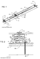
- FIG. 1 is a cross-section view of one embodiment of this invention showing the frames for the solar cell modules and the solar cell module retaining structure using the holding members.
- FIG. 2 is an enlarged cross-section view of the details of A in FIG. 1 .
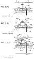
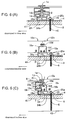
- FIG. 3 (A) is a side surface view of FIG. 2 ;
- FIG. 3(B) is a side surface view of the side surface frames and side surface caps different from FIG. 3 (A);
- FIG. 3 (C) is a side surface view of one portion FIG. 3 (B) in a cross-section.
- FIG. 3 (A) is a side surface view of FIG. 2 ;
- FIG. 3(B) is a side surface view of the side surface frames and side surface caps different from FIG. 3 (A);
- FIG. 3 (C) is a side surface view of one portion FIG. 3 (B) in a cross-section.
- FIG. 3 (A) is a side surface view of FIG. 2
- FIG. 3(B) is a side surface
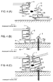
- FIG. 4 is an explanation view of the installation process summary for the solar cell module in FIGS. 1 and 2 .
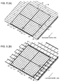
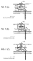
- FIG. 5 (A) is a perspective view of the condition where the solar cell module is installed on the roof material using the solar cell module retaining structure as shown in FIG. 1 ; and
- FIG. 5 (B) is a perspective view of the condition where the height of the surface of the solar cell module and the adjacent roof material are the same using the solar cell module retaining structure as shown in FIG. 1 .
- the frame 1 can be slid into a position of supporting member 42, such as a rafter, which supports a sheathing slope 41 with a predetermined interval and is completely fastened by the holding member 2 using a fastener 5 such as a bolt.
- the frames 1 adjacent to two solar cell modules positioned in an extending direction of the supporting member 42 are in contact with each other and are connected to make an almost flush surface.
- this example uses a cosmetic cover 1a which improves the design of the solar cell module on a downward incline side (solar cell array).
- a cross-section shape of the frame 1 for the solar cell module has a rectangle portion with a rectangle bottom surface arranged around middle section thereof relative to the height of the frame 1; a C-shaped insertion support portion 11 formed on the right surface thereof which has an opening at the first side surface side and into which an end of a module glass 6 in a solar cell panel body is inserted and supported; and a connection portion 12 formed and opened at the other side surface side opposite to the first side surface side around a lower right internal portion of the rectangular shape.
- there is an L-shaped bottom portion 14 which extends from the first side surface side of the rectangular to a lower side thereof, and then to the other side surface side.
- an engagement protrusion 13 has an arrow-shaped end portion 13a around the center of the connection portion 12 and the bottom portion 14, which extends in the same direction as the bottom portion 14 and has a top projecting upward. Also, a publicly known sealing member is placed between the end of the module glass 6 and the insertion support portion 11.
- the other side surface side of the frame 1 (the center of FIG. 4(A) or the right side surface) has the most projected section approximately from an upper surface and the insertion support portion 11, and the amount of the projection around the lower portion of the connection portion at the lower side, the engagement protrusion 13 and the other side surface side end of the bottom portion 14 is greater than the most projected section and less than that of the section around the above-mentioned insertion support portion 11.
- the end of the other side surface side of the engagement protrusion 13 is positioned more toward the first side surface side than the bottom portion 14.
- connection portion 12 of the frame 1 there is a C-shaped chamfer on an upper portion of the open side of the connection portion 12 of the frame 1, and the C-shaped chamfer makes the upper portion of the opening of the connection portion 12 incline. Also, an end of the lower portion of the open side of the connection portion 12 of the frame 1 and an end of the other side surface side of the bottom portion 14 are bent together to face each other where these other side surface side ends are positioned on an almost flush surface line (i.e., the amount of projection at the other side surface side is the same).
- the frame 1 has screw holes at an inner side of the other side surface side between the insertion support portion 11, the connection portion 12, and an inner side of one side surface side between the engagement protrusion 13 and the bottom portion 14, which can be used to assemble the frames 1 to build a framework.
- the material of the frame 1 is an aluminum extruded material with the same cross-section shapes, and colors thereof can be black, silver, brown, etc.
- the module glasses 6 has a pair of facing sides (downward incline side and upward incline side) where the frames 1 are fastened, and side surface frames 10, 10a are fastened on sides orthogonal to the pair of facing sides, where the side surface frames 10, 10a are fastened at the ends of the frames 1 by frame fastening screws 10e.
- the frames 1 and the side surface frames 10, 10a are fastened around the rectangular module glasses 6, thereby forming the rectangular solar cell module.
- the frames 1 and the side surface frames 10, 10a have different cross-section shapes.
- the holding member 2 comprises a pair of connecting portions 21 which can be inserted in the connection portions 12 of the frames 1 and extending in the direction spreading apart from each other; a downward section 22 extending downward from around the middle portions of the pair of connecting portions 21; and a seat section 24 arranged at a lower end of the downward section 22 and capable of mounting the bottom portion 14 of the frame 1 thereon.
- the holding member 2 has a connecting portion 23 which extends leftward from the downward section 22 between the connecting portion 21 and the seat section surface 24a, and has an arrow-shaped end 23a with its end projecting downward.
- This seat section 24 has a rectangular section at the right lower side from a connecting point with the downward section 22 and a C-shaped portion at a left lower side with an opening at the lower side whose size is almost equal to the right lower side rectangle.
- the seat section surface 24a can mount the bottom portion 14 of the frame 1 thereon and has a waterproof rubber 3 (e.g., butyl rubber), which gives a waterproof effect and corresponds to the rough surface (convex-concave surface) of the roof material 4, attached at a lower side of a seat section lower surface 24b.
- the holding member 2 has a holding portion 25, which extends in the opposite direction away from the connecting portion 23 from the seat section lower surface 24a so as to hold the supporting member 42.
- This holding member 2 is formed in an almost T shape by a pair of the connecting portions 21 and the downward section 22 and is designed to adjoin the end of the opening side lower portion of the connection portion 12 of the frame 1 and the other side surface side end of the bottom portion 14 at the side surface of the downward section 22, where the frame 1 has its movement restricted toward the other side surface side by the downward section 22.
- the C-shaped chamfer is formed at an angled portion of the end lower side of the connecting portion 21, and the C-shaped chamfer makes the end lower side of the connecting portion incline.
- the material of the frame 2 is an aluminum extruded material with the same cross-section shapes, and colors thereof can be black and silver.
- the length of the holding member 2 is preferably between 100 mm - 200 mm relative to the extrusion direction, and the holding member 2 is designed shorter than the frame, thereby allowing it to slide.
- the height adjustment can be done by the adjacent roof materials between the seat section surface 24a of the seat section 24 of the holding member 2 and the seat section lower surface 24b.
- a flat roof made from asphalt shingle or straight roof material can be arranged to be lowered for a module cable 61 ( FIG. 1 ) to pass through, and the distance/height between the roof material 4 and the bottom surface 14 of the frame 1 can be 7 mm.
- the surfaces of the adjacent roof materials 4a and the frames 1 can have approximately the same height when the roof materials 4a are thicker, such as roof tiles, where adjusting the height gives the feeling of integrity with the building and improves the design.
- the starter fixture 2a functioning as the holding member 2 is fastened to the supporting member 42, such as a roof, and the first solar cell module is arranged at the downward incline side (opposite to the upward incline side) where the frame 1 of one side (upward incline side) of the first solar cell module is connected to the starter fixture 2a.
- the holding member 2 is connected to the side (downward incline side) opposite to the side where the starter fixture 2a is connected.
- the holding portion 25 of the holding member 2 fastened to the supporting member 42 connected to the frame 1 of the solar cell module so as to face the direction of the side opposite to the solar cell module. Then, the holding member 2 can be slid relative to the frame 1 to fasten the position of the holding member 2 on the supporting member 42 supporting the sheathing slope 41 with the predetermined intervals, thereby fastening the first solar cell module to the supporting member 42.
- the frame 1 at the upward incline side of the second solar cell module is connected at the downward incline side thereof. Accordingly, two adjacent frames 1 of the solar cell modules are in contact with each other, and the holding members 2 are fastened to the supporting members 42 at the lower side of the second solar cell module.
- the holding member 2 is fastened to the frame 1 at the other side (downward incline side), and as stated above, the holding member 2 is fastened to the supporting member 42 so as to completely fasten the second solar cell module, wherein the above-mentioned operation can be repeated to fasten the solar cell modules to the supporting members 42 in order from the upward incline side toward the downward incline side.
- multiple solar cell modules can be fastened in order in one direction from a certain point (for example, the starter fixture 2a), and the standardization of the installation and installation cost reduction becomes possible.
- the holding member 2 is approximately arranged at the position of the supporting member 42 supporting the sheathing slope 41 with the predetermined intervals, and the engagement protrusion 13 of the frame 1 and the engaging protrusion 23 of the holding member 2 are used to make an engagement in between.
- the engagement between engagement protrusion 13 and the engaging protrusion 23 restricts the movement in the right-angle direction relative to the extension direction of the frame 1, which enables the disengagement of the holding member 2 at the installation process and smooth sliding, thereby reducing the cost of manufacturing and assembling.
- the holding member 2 can be arranged at a position to be fastened to the supporting member 42, a separate peeling paper (not shown in the figures) of the waterproof rubber 3, corresponding to the rough surface (convex-concave surface) of the waterproof and the roof material 4 underneath the lower surface 24b of the seat section, is peeled off, and the holding member 2 is arranged on the surface of the roof material 4 at an appropriate position.
- the holding member 2 is completely fastened to the supporting member 42 by a fastener 5 utilizing the holding screw hole 25a of the holding portion 25, and the solar cell module is fastened to the supporting member 42.
- an external force applied on the solar cell module for example, wind load and earthquake load
- the solar cell module does not interfere even if it slants, which allows these members to be slanted as they are connected, thereby providing and easy and cost-saving installation.
- FIG. 5 (A) illustrates an example of installation where the solar cell module retaining structure described above is arranged on the roof material 4 (such as a thinner roof material such as asphalt shingle or straight roof material).
- the roof material 4 such as a thinner roof material such as asphalt shingle or straight roof material.
- Height adjustment between the seat section surface 24a of the seat section 24 of the holding member 2 and the seat section lower surface 24b thereof can be operated, and the position where the module cable passes can be lowered to arrange the height between the roof material 4 and the lower surface of the bottom portion 14 of the frame 1 to be 7 mm, which gives the feeling of integrity with the building and improves the design.
- FIG. 5 (B) illustrates an example of an installation where the surface of the frame 1 of the above-mentioned solar cell module retaining structure and the surface of the adjacent roof material 4a (for example, a thicker roof material such as roof tiles) are almost the same height.
- the height of the seat section surface 24a of the seat section 24 of the holding member 2 and the seat section lower surface 24b can be adjusted, and with respect to the roof material 4a with thicker adjacent roof material, such as roof tiles, since the surfaces of the adjacent roof materials 4a and the frames 1 can have approximately the same height, adjusting the height gives the feeling of integrity with the building and improves the design.
- the side surface cap 10b can be used to cover and close the facing notched grooves 10d of the side surface frames 10a.
- the side surface cap 10b can be aluminum or a color steel plate (such as a galbarium steel plate), with the frame 1 and the side surface frame 10a having the same color.
- the size of the notched groove 10d of the side surface frame 10a is arranged so that the connecting portion 21 of the holding member 2 and the engaging protrusion 23 do not interfere. Then, the side surface cap 10b can be attached to the frame 1 using a portion of the frame fastening screw 10e in order to bridge two solar cell modules.
- the solar cell modules can be removed from the holding members 2 through the notched grooves 10d when maintenance of the solar cell modules is being performed.
- the arrangement of the side surface cap 10b increases the design of the solar cell modules and prevents the horizontal/lateral disengagement of the solar cell modules, and when maintenance after installing the solar cell module is necessary, the solar cell modules can be removed without removing the holding member 2 from the roof material 4, and it is possible to perform the maintenance operation and reduce the risk of breaking the roof material 4 and leakage.
- the number of members relating to the solar cell module retaining structure can be reduced and standardizing the installation process is possible, which reduces the cost of manufacturing and installation, and improves the design thereof.
- the holding member 2 can slide freely relative to the frame 1, and therefore the holding member 2 can be positioned on the supporting member 42 supporting the sheathing slope 31 with the predetermined intervals, and the fastener 5 can be used to firmly fasten the solar cell module.
- the solar cell modules of the downward incline side can be fastened with the holding members 2.
- the holding portion 25 of the holding member 2 to be fastened at the supporting member 42 is fastened at the supporting member 42 at the lower side of the solar cell module at the downward incline side, thereby making the frames 1 come in contact with each other.
- the solar cell modules are connected to make an almost flush surface, which improves the design without using a member such as a cover.
- the frames 1 of the solar cell modules arranged adjacent to each other are connected to each other, as long as the solar cell modules are the same size, an installation surface of the solar cell module can be minimized, thereby preventing the reduction of the number of installations of the solar cell modules on roofs, etc.
- the frames 1 are designed to have matching cross-section surfaces with two facing sides of the solar cell module, the frames 1 with different cross-section surface shapes are not necessary for the solar cell module to be fastened to the supporting member, which reduces the number of parts, cutting down the manufacturing cost of the solar cell module retaining structure.
- a conventional module glass 6 (solar cell panel body) with solar cells can be inserted and supported.
- one solar cell module and the adjacent other solar cell module can be electrically connected via the side surface cap 10b and the frame holding screw 10e, and therefore, there is no need to separately install the cables for groundings and prepare additional parts for the groundings when installing groundings between the solar cell modules, and the solar cell modules can easily be connected each other, which reduces the cost in relation to the grounding.
- the screw hole for fastening the side surface frame 10a of the frame 1 is also used to install the side surface cap 10b; however, as shown in FIGS. 6 (A) - 6 (C) , the screw hole 14b for the side surface cap can be created on the frame 1 e, and the side surface cap 10c can be fastened by the side surface cap holding screw 10f. Furthermore, the side surface cap 10c is sized to be in the notched grooves 10d of the facing side surface frames 10a and has the same height as the side surface frames 10a, which improves the design thereof.
- the frame holding screw 10e for fastening the frames 1 and the side surface frames 10a to be loosened, removing the possibility of loosening the frame connections.
- the side surface cap holding screw 10f is required; however, as shown in FIG. 6 (C) , the frame holding screw 10e and the side surface cap holding screw 10f are clearly separated, which provides better maintenance access and eliminates the chance of mistaking the removal screw.
- the engagement protrusion 13 of the frame 1 has an arrow-shaped end portion 13a with a projecting top on the frame 1 and the engaging protrusion 23 has the arrow-shaped end portion 23a with projecting lower end on the holding member 2; however, this invention is not limited thereto, and L-shaped end 13b as in FIG. 7 (A) and the L-shaped end 23b are possible.
- the L-shaped end 13b of the engagement protrusion 13 and the L-shaped end 23b of the engaging portion 23 provide firmer engagement than the arrow-shaped engagement.
- the holding member 2 is arranged at an approximate position on the supporting member 42 supporting the sheathing slope 41 with the predetermined intervals, and the engagement protrusion 13 of the frame 1 and the engaging protrusion 23 of the holding member 2 are used to make an engagement in between; however, when installing on a vertical/perpendicular wall, the load on the engagement protrusion 13 and the engaging protrusion 23 increases. Accordingly, the L-shaped end 13b of the frame 1b and the L-shaped end 23b of the holding member 2b provide a firmer engagement force.
- the frame 1c can be equipped with an extending piece 14a extending to an opposite side of the bottom portion 14 of the frame.
- the extending piece 14a increases the strength of the frame 1c against the deflection compared to the frame 1 with respect to X direction (the direction along the supporting member) and Y direction (the right-angle direction facing the supporting member). For example, a stronger frame 1 is necessary when installing the solar cell module in a snowy area or an area that often encounters strong gusts of wind.
- the extending piece 14a functions as the reinforcement part for the frame 1.
- the engagement protrusion 13 has an arrow-shaped end portion 13a around the center of the connection portion 12 and the bottom portion 14, extending in the same direction as the bottom portion 14 and having an arrow projecting top
- the engaging protrusion 23 has an arrow-shaped end portion 23a, extending to the left side from the down portion 22 between the connecting portion 21 and the seat section surface 24a and having the projecting lower end; however, this invention is not limited thereto, and as shown in FIG. 7 (C) , the L-shaped end 13c and the L-shaped end 23c are possible.
- the L-shaped end portion 13c can be located at the end of the bottom portion 14 of the frame 1, and the engaging portion 23 of the holding member 2 can engage the L-shaped end portion 23c. Accordingly, unlike the frame 1, there is no need for the engagement protrusion 13, and the functions of the bottom portion 14 and the engagement protrusion can be shared, reducing the necessary area space and the cost of frame 1.
Landscapes
- Engineering & Computer Science (AREA)
- Physics & Mathematics (AREA)
- Chemical & Material Sciences (AREA)
- General Engineering & Computer Science (AREA)
- Mechanical Engineering (AREA)
- Combustion & Propulsion (AREA)
- Sustainable Energy (AREA)
- Thermal Sciences (AREA)
- Life Sciences & Earth Sciences (AREA)
- Sustainable Development (AREA)
- Structural Engineering (AREA)
- Civil Engineering (AREA)
- Architecture (AREA)
- Condensed Matter Physics & Semiconductors (AREA)
- Power Engineering (AREA)
- Microelectronics & Electronic Packaging (AREA)
- Computer Hardware Design (AREA)
- General Physics & Mathematics (AREA)
- Electromagnetism (AREA)
- Photovoltaic Devices (AREA)
- Roof Covering Using Slabs Or Stiff Sheets (AREA)
Claims (7)
- Structure de retenue pour module de cellule solaire destinée à fixer un module de cellule solaire sur un élément de support (42), dans laquelle
le module de cellule solaire inclut un corps de panneau de cellule solaire (6) dont la forme est plane et est constituée par une pluralité de bordures, le corps de panneau de cellule solaire incluant une cellule solaire et des cadres (1) à fixer à au moins une paire de bordures face à face des corps de panneaux de cellules solaires adjacents l'un à l'autre et grâce à quoi le module de cellule solaire est capable d'être fixé sur l'élément de support en connectant chacun des éléments de maintien (2) aux cadres fixés respectivement sur la paire de bordures face à face des corps de panneaux de cellules solaires adjacents l'un à l'autre, et en fixant chaque élément de maintien à l'élément de support, dans laquelle chacun des éléments de maintien est capable de coulisser par rapport au cadre et connecte les deux modules de cellules solaires agencés dans une direction d'extension de l'élément de support de telle façon que les cadres des corps de panneaux de cellules solaires des deux modules de cellules solaires soient adjacents l'un à l'autre, et de telle façon que les deux modules de cellules solaires réalisent sensiblement une surface en affleurement ; et dans laquelle chacun des éléments de maintien restreint en outre le mouvement de l'un des deux modules de cellules solaires dans une direction perpendiculaire à une direction d'extension des cadres ; et est fixé sur l'élément de support au-dessous de l'autre des deux modules de cellules solaires, et dans laquelle
le cadre, configuré pour s'étendre dans une direction longitudinale tout en ayant la même section transversale dans une direction longitudinale, comprend :une portion de support d'insertion en forme de C (11) ayant une ouverture en forme de C sur un côté, la bordure du corps de panneau de cellule solaire capable d'être inséré dans la portion de support d'insertion en forme de C, et supportée par la portion de support d'insertion en forme de C ;une portion de connexion (12) agencée au-dessous de la portion de support d'insertion en forme de C et ayant une ouverture sur l'autre côté opposé au premier côté ; etune projection d'engagement (13) agencée au-dessous de la portion de connexion et ayant une ouverture sur l'autre côté, une portion terminale (13a) de la projection d'engagement se projetant vers le haut, etl'élément de maintien, configuré pour être plus court que le cadre dans une direction longitudinale tout en ayant la même section transversale dans une direction longitudinale, l'élément de maintien comprenant en outre :une paire de portions de connexion (21) capables d'être insérées dans la portion de connexion et s'étendant dans une direction en éloignement l'une de l'autre ;une section descendante (22) s'étendant vers le bas depuis la paire de portions de connexion ;une section formant siège (24) agencée à l'extrémité inférieure de la section descendante et capable de recevoir un fond du cadre monté sur elle-méme ;une pièce d'engagement (23) agencée sur la section descendante entre la section formant siège et la portion de connexion, et s'étendant depuis la section descendante dans la même direction qu'une direction de la portion de connexion, la pièce d'engagement ayant une portion d'engagement en projection (23a) qui se projette vers le bas de manière à engager la projection d'engagement de cadre ; etune portion de maintien (25) ayant une surface inférieure sur la même surface qu'une surface de fond de la section formant siège et s'étendant dans une direction opposée à une direction de la pièce d'engagement de manière à être fixée sur l'élément de support. - Structure de retenue pour module de cellule solaire selon la revendication 1, dans laquelle
l'autre module de cellule solaire est placé sur une toiture en pente, sur un côté de celle-ci incliné vers le bas, avec l'élément de maintien (2) entre eux. - Structure de retenue pour module de cellule solaire selon la revendication 1, dans laquelle
le sommet du cadre (1) est incliné du côté ouvert de la portion de connexion (21) de celui-ci, et une portion de l'élément de maintien (2) est inclinée sur le côté inférieur de l'extrémité de la portion de connexion. - Structure de retenue pour module de cellule solaire selon la revendication 1, comprenant en outre
un cadre de surface latérale (10a), qui est fixé sur un côté différent d'un côté où le cadre (1) est fixé autour du corps du panneau de cellule solaire, comporte une gorge en encoche (10d) à travers laquelle peut passer l'élément de maintien (2), un capuchon de surface latérale (10b) qui couvre la gorge en encoche du cadre de surface latérale, et qui est fixé au cadre, dans laquelle
en supprimant le capuchon de surface latérale alors que l'élément de support est supporté par l'élément de support (42), le module de cellule solaire fixé par l'élément de maintien peut être glissé dans la direction d'extension du cadre pour enlever le module de cellule solaire vis-à-vis de l'élément de maintien. - Élément de maintien (2) pour la structure de retenue pour module de cellule solaire selon la revendication 1, destinée à être fixée sur un élément de support prédéterminé du module de cellule solaire via un cadre qui s'étend dans le sens de la longueur dans une section transversale, et configuré pour être plus court que le cadre dans une direction longitudinale tout en ayant la même section transversale dans une direction longitudinale, comprenant :une paire de portions de connexion (21) capables d'être insérées dans la portion de connexion et s'étendant dans une direction en éloignement l'une de l'autre ;une section descendante (22) s'étendant vers le bas depuis la paire de portions de connexion ;une section formant siège (24) agencée à l'extrémité inférieure de la section descendante et capable de recevoir un fond du cadre monté sur elle-méme ;une pièce d'engagement (23) agencée sur la section descendante entre la section formant siège et la portion de connexion, et s'étendant depuis la section descendante dans la même direction qu'une direction de la portion de connexion, la pièce d'engagement ayant une portion en projection d'engagement (23a) qui se projette vers le bas de manière à engager la projection d'engagement du cadre ; etune portion de maintien (25) ayant une surface inférieure sur la même surface qu'une surface inférieure de la section formant siège et s'étendant dans une direction opposée à une direction de la pièce d'engagement de manière à être fixée à l'élément de support.
- Élément de maintien selon la revendication 5, dans lequel
la section formant siège (24) s'étend plus loin que l'extension de la portion de connexion (12). - Élément de maintien selon les revendications 5 ou 6, dans lequel la hauteur de celui-ci est conçue pour ladite section formant siège (24) afin de former un jeu suffisant entre la surface inférieure du cadre (1) et l'élément de support (42), jeu à travers lequel peut passer un câble de module connecté au corps de panneau de cellule solaire, et la surface supérieure du corps de module de cellule solaire est capable d'être ajustée de sorte que sa hauteur est approximativement égale à celle d'un matériau de toiture monté sur l'élément de support.
Applications Claiming Priority (2)
| Application Number | Priority Date | Filing Date | Title |
|---|---|---|---|
| JP2007153463A JP4290750B2 (ja) | 2007-06-11 | 2007-06-11 | 太陽電池モジュールの固定構造、太陽電池モジュール用のフレーム及び固定部材 |
| PCT/JP2007/068617 WO2008152748A1 (fr) | 2007-06-11 | 2007-09-26 | Structure de fixation d'un module de batterie solaire, cadre pour le module de batterie solaire, et élément de fixation |
Publications (3)
| Publication Number | Publication Date |
|---|---|
| EP2169139A1 EP2169139A1 (fr) | 2010-03-31 |
| EP2169139A4 EP2169139A4 (fr) | 2010-12-08 |
| EP2169139B1 true EP2169139B1 (fr) | 2016-01-27 |
Family
ID=40094740
Family Applications (1)
| Application Number | Title | Priority Date | Filing Date |
|---|---|---|---|
| EP07828390.0A Not-in-force EP2169139B1 (fr) | 2007-06-11 | 2007-09-26 | Structure de fixation d'un module de batterie solaire, cadre pour le module de batterie solaire, et élément de fixation |
Country Status (7)
| Country | Link |
|---|---|
| US (1) | US7956280B2 (fr) |
| EP (1) | EP2169139B1 (fr) |
| JP (1) | JP4290750B2 (fr) |
| KR (1) | KR101355881B1 (fr) |
| CN (1) | CN101802324B (fr) |
| AU (1) | AU2007355014B2 (fr) |
| WO (1) | WO2008152748A1 (fr) |
Cited By (1)
| Publication number | Priority date | Publication date | Assignee | Title |
|---|---|---|---|---|
| CN107819426A (zh) * | 2017-10-12 | 2018-03-20 | 山东新华联智能光伏有限公司 | 光伏系统 |
Families Citing this family (144)
| Publication number | Priority date | Publication date | Assignee | Title |
|---|---|---|---|---|
| JP4684874B2 (ja) * | 2005-12-13 | 2011-05-18 | 株式会社屋根技術研究所 | 太陽電池モジュール枠体 |
| EP2008343B1 (fr) * | 2006-03-09 | 2017-08-09 | SunPower Corporation, Systems | Pince de montage de module photovoltaique avec mise à la terre integrée |
| SI2132495T1 (sl) * | 2007-03-30 | 2011-04-29 | Haticon Gmbh | Pritrjevalna naprava za solarne module |
| KR20100024989A (ko) * | 2007-06-19 | 2010-03-08 | 비피 코포레이션 노쓰 아메리카 인코포레이티드 | 태양열 패널을 장착시키기 위한 프레임을 구비하는 태양열 모듈 |
| JP2009164434A (ja) * | 2008-01-08 | 2009-07-23 | Sharp Corp | 太陽電池モジュール |
| WO2009129293A2 (fr) * | 2008-04-15 | 2009-10-22 | The Penn State Research Foundation | Système de paroi transparente autoporteuse |
| KR100921658B1 (ko) * | 2008-10-06 | 2009-10-15 | 한국철강 주식회사 | 태양전지 모듈 |
| CN102245979A (zh) * | 2008-10-11 | 2011-11-16 | 美国太阳能股份有限公司 | 高效安装的太阳能面板系统 |
| US11063553B2 (en) | 2008-11-17 | 2021-07-13 | Kbfx Llc | Solar carports, solar-tracking carports, and methods |
| FR2938566B1 (fr) * | 2008-11-17 | 2012-01-13 | Alain Poivet | Dispositif de support de panneaux de cellules photovoltaiques et systeme de support de panneaux photovoltaiques |
| US10277159B2 (en) | 2008-11-17 | 2019-04-30 | Kbfx Llc | Finished multi-sensor units |
| FR2940884B1 (fr) * | 2009-01-09 | 2010-12-24 | Jean Paul Pierre Marie Guiol | Systeme de fixations de panneaux solaires photovoltaiques sur des serres agricoles, horticoles, arboricoles pour tunnel, chapelle multi-chapelles en couverture plastique ou en verre. |
| WO2010081890A1 (fr) * | 2009-01-19 | 2010-07-22 | Innate Pharma | Anticorps anti-kir3d |
| DE202009001098U1 (de) * | 2009-01-27 | 2009-04-30 | Mounting Systems Gmbh | Solarmodulbefestigung |
| US8826618B2 (en) | 2011-03-15 | 2014-09-09 | Vermont Slate & Copper Services, Inc. | Roof mount assembly |
| US9134044B2 (en) | 2010-01-25 | 2015-09-15 | Vermont Slate & Copper Services, Inc. | Roof mount assembly |
| US10151114B2 (en) | 2010-01-25 | 2018-12-11 | Rillito River Solar, Llc | Roof mount assembly |
| US8153700B2 (en) | 2010-03-19 | 2012-04-10 | Vermont Slate & Copper Services, Inc. | Roofing system and method |
| US9447988B2 (en) | 2010-01-25 | 2016-09-20 | Rillito Rive Solar, LLC | Roof mount assembly |
| US8209914B2 (en) | 2010-01-25 | 2012-07-03 | Vermont Slate & Copper Services, Inc. | Roofing grommet forming a seal between a roof-mounted structure and a roof |
| DE102009010225A1 (de) * | 2009-02-23 | 2010-09-02 | Solon Se | Solaranlage aus zumindest einem Solarmodul mit einer federnden Lagerung der Abdeckplatte |
| US8316590B2 (en) | 2009-03-20 | 2012-11-27 | Northern States Metals Company | Support system for solar panels |
| US20110220596A1 (en) * | 2009-03-20 | 2011-09-15 | Northern States Metals Company | Support system for solar panels |
| US8240109B2 (en) * | 2009-03-20 | 2012-08-14 | Northern States Metals Company | Support system for solar panels |
| US8256169B2 (en) * | 2009-03-20 | 2012-09-04 | Northern States Metals Company | Support system for solar panels |
| WO2010111383A2 (fr) * | 2009-03-24 | 2010-09-30 | Jenkins Robert L | Systèmes photovoltaïques, procédés pour installer des systèmes photovoltaïques, et kits pour installer des systèmes photovoltaïques |
| JP4465406B1 (ja) * | 2009-04-16 | 2010-05-19 | 株式会社屋根技術研究所 | 連結部材 |
| JP4365450B1 (ja) | 2009-05-01 | 2009-11-18 | 株式会社屋根技術研究所 | 太陽電池モジュールの固定構造、太陽電池モジュール用のフレーム及び固定部材 |
| US8690110B2 (en) * | 2009-05-25 | 2014-04-08 | Solaredge Technologies Ltd. | Bracket for connection of a junction box to photovoltaic panels |
| DE202009007526U1 (de) * | 2009-05-27 | 2009-08-20 | Schletter Gmbh | Vorrichtung zur Befestigung einer Montageschiene an einem Gewindeschaft |
| DE202009008931U1 (de) * | 2009-06-29 | 2009-09-24 | Meinhardt, Dirk | Gebäudehülle mit Solarkollektormodul(en) und Montagesystem dafür |
| US8991114B2 (en) | 2009-07-02 | 2015-03-31 | Zep Solar, Llc | Pivot-fit connection apparatus, system, and method for photovoltaic modules |
| US9518596B2 (en) * | 2009-07-02 | 2016-12-13 | Solarcity Corporation | Pivot-fit frame, system and method for photovoltaic modules |
| DE202010000293U1 (de) * | 2009-10-09 | 2010-05-20 | Galaxy-Energy Gmbh | Solardachanordnung |
| ITMI20092031A1 (it) * | 2009-11-18 | 2011-05-19 | Bm S P A | Dispositivo di sostegno ed ausilio al fissaggio di pannelli solari e simili |
| FR2953237B1 (fr) * | 2009-12-01 | 2012-04-06 | Jean Pierre Parneix | Dispositif d'encadrement compose d'une pluralite de panneaux et profiles de fixation sur une structure support formant un element de couverture etanche |
| KR20120110104A (ko) * | 2009-12-25 | 2012-10-09 | 가부시키가이샤 야네기주쓰켄큐조 | 보조부재 |
| JP4688951B1 (ja) * | 2009-12-25 | 2011-05-25 | シャープ株式会社 | 構造物設置架台、構造物設置用支持具、及び太陽光発電システム |
| US10472828B2 (en) | 2010-01-25 | 2019-11-12 | EcoFasten Solar, LLC | Roof mounting system |
| US20110209422A1 (en) * | 2010-02-18 | 2011-09-01 | King Zachary A | Method and apparatus for mounting photovoltaic modules to shingled surfaces |
| FR2964129A1 (fr) * | 2010-02-25 | 2012-03-02 | Dome Solar | Dispositif permettant de fixer des panneaux photovoltaiques avec une membrane d'etancheite |
| US8595996B2 (en) * | 2010-02-26 | 2013-12-03 | General Electric Company | Photovoltaic framed module array mount utilizing asymmetric rail |
| US10054336B2 (en) * | 2010-03-03 | 2018-08-21 | Robert M. M. Haddock | Photovoltaic module mounting assembly |
| US8495839B2 (en) * | 2010-04-01 | 2013-07-30 | Yanegijutsukenkyujo Co., Ltd. | Installation structure of solar cell module |
| US8424256B2 (en) * | 2010-04-01 | 2013-04-23 | Thomas Lawson Cook | Asphalt roof integrated photovoltaic |
| US8181402B2 (en) * | 2010-04-01 | 2012-05-22 | Yanegijutsukenkyujo Co., Ltd. | Building-integrated photovoltaic power unit |
| DE202010006442U1 (de) * | 2010-05-04 | 2010-08-19 | Ideematec Deutschland Gmbh | Gestell zur Befestigung von Solarmodulen |
| WO2011154019A1 (fr) * | 2010-06-08 | 2011-12-15 | Renusol Gmbh | Système de montage pour panneaux solaires et dispositif de fixation |
| KR101122601B1 (ko) * | 2010-06-29 | 2012-03-16 | 수림금속 주식회사 | 태양광 모듈용 프레임 |
| USD759464S1 (en) | 2010-07-02 | 2016-06-21 | Solarcity Corporation | Leveling foot |
| JP5501125B2 (ja) * | 2010-07-06 | 2014-05-21 | 株式会社屋根技術研究所 | 固定部材 |
| US8418983B2 (en) | 2010-07-29 | 2013-04-16 | First Solar, Inc. | Slider clip and photovoltaic structure mounting system |
| JP5611716B2 (ja) | 2010-08-16 | 2014-10-22 | 株式会社屋根技術研究所 | 板状モジュールの固定構造 |
| DE202010017458U1 (de) * | 2010-09-01 | 2011-11-14 | Mounting Systems Gmbh | Profilschiene, Halteelement und damit gebildete Solarmodulanordnung, insbesondere für eine Quermontage von Solarmodulen |
| US20120073630A1 (en) * | 2010-09-28 | 2012-03-29 | Perfect Source Technology Corp. | Rectangular protective frame for solar cell module |
| US20120097807A1 (en) * | 2010-10-25 | 2012-04-26 | Rees Kyle J | Solar panel support system |
| CA2820935A1 (fr) | 2010-12-09 | 2012-06-14 | Zep Solar, Inc. | Appareil et systeme de liaison pivot pour panneaux photovoltaiques |
| JP5909499B2 (ja) | 2010-12-09 | 2016-04-26 | ソーラーシティ コーポレーション | 光起電力アレイ用のスカート |
| US20160305459A1 (en) | 2010-12-10 | 2016-10-20 | Solar Clam-P | Panel Mounting System and Method |
| WO2012086271A1 (fr) * | 2010-12-22 | 2012-06-28 | 日晴金属株式会社 | Dispositif de fixation pour module de batterie solaire |
| US8701361B2 (en) * | 2011-01-12 | 2014-04-22 | Pierino Ferrara | Rooftop system with integrated photovoltaic modules and method for constructing the same |
| US8839573B2 (en) | 2011-02-11 | 2014-09-23 | Northern States Metals Company | Spring clip |
| AU2012220665B2 (en) | 2011-02-22 | 2017-04-13 | Solarcity Corporation | Pivot-fit frame, system and method for photovoltaic modules |
| US9611652B2 (en) | 2011-02-25 | 2017-04-04 | Dustin M. M. Haddock | Mounting device for building surfaces having elongated mounting slot |
| JP2012202132A (ja) * | 2011-03-25 | 2012-10-22 | Noritz Corp | 太陽電池パネルの固定構造 |
| US10041693B2 (en) * | 2011-03-30 | 2018-08-07 | Daniel Joseph Rheaume | Solar-powered ridge vent fan unit |
| US8448407B1 (en) | 2011-03-30 | 2013-05-28 | Gregory M. Wiener | Roof mounting assembly |
| US8631629B1 (en) | 2011-03-30 | 2014-01-21 | Gregory M. Wiener | Roof mounting assembly |
| US8776454B2 (en) | 2011-04-05 | 2014-07-15 | Michael Zuritis | Solar array support structure, mounting rail and method of installation thereof |
| CA2739766C (fr) * | 2011-05-10 | 2016-08-23 | Robert Richardson | Panneau solaire pour toiture inclinee classique pouvant etre integre entre les bardeaux |
| WO2012165437A1 (fr) * | 2011-06-03 | 2012-12-06 | 京セラ株式会社 | Matrice de cellules photovoltaïques |
| US8683751B2 (en) | 2011-07-08 | 2014-04-01 | Vermont Slate & Copper Services, Inc. | Roof mount having built-in failure |
| CN102299186B (zh) * | 2011-08-25 | 2013-06-26 | 浙江正泰太阳能科技有限公司 | 一种太阳能电池板安装固定装置及安装固定方法 |
| WO2013033670A1 (fr) * | 2011-09-02 | 2013-03-07 | Rterra Holdings, Llc | Système de montage pour réseaux photovoltaïques |
| US10008974B2 (en) | 2011-09-02 | 2018-06-26 | Pv Solutions, Llc | Mounting system for photovoltaic arrays |
| WO2013033687A1 (fr) | 2011-09-02 | 2013-03-07 | Rtetta Holdings, Llc | Système de suivi et d'attribution de contributions d'énergie renouvelable à un système d'énergie renouvelable modulaire |
| US11022343B2 (en) | 2011-09-02 | 2021-06-01 | Pv Solutions, Llc | Mounting system for photovoltaic arrays |
| WO2013043816A1 (fr) | 2011-09-23 | 2013-03-28 | Vermont Slate & Copper Services, Inc. | Ensemble de montage de toit et son procédé de montage |
| US9212833B2 (en) | 2011-09-23 | 2015-12-15 | Vermont Slate and Copper Services, Inc. | Power grip button |
| US9038329B2 (en) * | 2011-10-11 | 2015-05-26 | Sunlink Corporation | Structure following roof mounted photovoltaic system |
| USD765591S1 (en) | 2011-12-09 | 2016-09-06 | Solarcity Corporation | Panel skirt and photovoltaic panel |
| EP2604949A1 (fr) * | 2011-12-14 | 2013-06-19 | Renusol GmbH | Dispositif de retenue destiné à la retenue d'un module photovoltaïque sur un rail de montage |
| WO2013101597A1 (fr) | 2011-12-29 | 2013-07-04 | Haddock Dustin M M | Dispositif de montage pour panneaux à joints debout |
| CA2800423A1 (fr) * | 2012-01-03 | 2013-07-03 | Certainteed Corporation | Elements de toiture photovoltaiques et systemes de toiture photovoltaiques |
| KR101198702B1 (ko) * | 2012-02-28 | 2012-11-12 | 주식회사 톱텍 | 태양전지모듈 고정장치 |
| US8505864B1 (en) * | 2012-02-29 | 2013-08-13 | Imp Inc. | PV kit for roof assembly |
| US8640402B1 (en) * | 2012-03-08 | 2014-02-04 | Henry H. Bilge | Building roof fascia, coping and/or solar panel connector arrangement |
| JP5917210B2 (ja) * | 2012-03-15 | 2016-05-11 | 本田技研工業株式会社 | 太陽電池モジュールの固定方法およびメンテナンス方法 |
| JP6046708B2 (ja) * | 2012-05-11 | 2016-12-21 | 京セラ株式会社 | 太陽電池装置 |
| CN102777454B (zh) * | 2012-06-28 | 2014-10-01 | 友达光电股份有限公司 | 太阳能装置及其扣合机构 |
| US9320926B2 (en) | 2012-06-28 | 2016-04-26 | Solarcity Corporation | Solar panel fire skirt |
| US8567134B1 (en) * | 2012-06-29 | 2013-10-29 | Sunpower Corporation | Snap-in and progressive locking photovoltaic module |
| US8875401B2 (en) * | 2012-07-18 | 2014-11-04 | Solarcity Corporation | Solar panel clamp system |
| JP5705380B2 (ja) * | 2012-07-23 | 2015-04-22 | 株式会社屋根技術研究所 | 太陽電池モジュールの固定構造 |
| JP5540045B2 (ja) * | 2012-07-27 | 2014-07-02 | 株式会社サニックス | 太陽電池モジュールの取付け構造 |
| CN102810582B (zh) * | 2012-08-14 | 2015-04-22 | 友达光电股份有限公司 | 太阳能装置及其框架组合 |
| US8740163B1 (en) * | 2012-10-31 | 2014-06-03 | Innovative Medical Products Inc. | Insulated connector for attaching a solar unit to a roof |
| KR101306909B1 (ko) * | 2012-11-12 | 2013-09-10 | 두원산업(주) | 지붕에 설치되는 태양전지모듈 지지대 |
| DE102012022738A1 (de) * | 2012-11-21 | 2014-05-22 | Adensis Gmbh | PV-Modul 6-Punkt Montageverfahren |
| KR20140082900A (ko) * | 2012-12-24 | 2014-07-03 | 삼성에스디아이 주식회사 | 태양광 발전장치 |
| KR101474526B1 (ko) * | 2013-02-21 | 2014-12-22 | (주)제이텍 | 온실용 파이프 지지유닛 |
| US9347691B2 (en) * | 2013-02-26 | 2016-05-24 | Solarcity Corporation | Torque Tube Mounted Photovoltaic Apparatus, System, and Method |
| US9303663B2 (en) | 2013-04-11 | 2016-04-05 | Northern States Metals Company | Locking rail alignment system |
| KR101368923B1 (ko) * | 2013-04-24 | 2014-03-04 | (주)에이비엠그린텍 | 태양전지모듈을 마감재로 사용하는 지붕패널 |
| US10256765B2 (en) | 2013-06-13 | 2019-04-09 | Building Materials Investment Corporation | Roof integrated photovoltaic system |
| CN104282791A (zh) * | 2013-07-10 | 2015-01-14 | 国电光伏有限公司 | 高效型太阳能电池 |
| US9080792B2 (en) * | 2013-07-31 | 2015-07-14 | Ironridge, Inc. | Method and apparatus for mounting solar panels |
| KR20150041932A (ko) | 2013-10-10 | 2015-04-20 | 엘지이노텍 주식회사 | 태양전지 모듈 |
| US9397605B2 (en) * | 2013-10-30 | 2016-07-19 | Kevin Stapleton | Panel mounting bracket with under-mounting clamp and related methods |
| EP3128098B1 (fr) * | 2014-03-31 | 2018-12-26 | Panasonic Intellectual Property Management Co., Ltd. | Appareil de cellules solaires |
| WO2016123357A2 (fr) | 2015-01-28 | 2016-08-04 | Pv Solutions, Llc | Système de raccordement de réseau photovoltaïque mécanique et électrique intégré |
| US11817818B2 (en) | 2015-07-24 | 2023-11-14 | Tecsi Solar, Inc. | Module frame with cable management flange |
| CN108352804B (zh) * | 2015-07-24 | 2021-06-25 | 泰科思太阳能公司 | 具有电缆管理凸缘的人体工学太阳能模块框架 |
| US20170053043A1 (en) * | 2015-08-21 | 2017-02-23 | Solarcity Corporation | Systems and methods for locating structures for rooftop solar panel installation |
| GB2541927A (en) * | 2015-09-04 | 2017-03-08 | Viridian Concepts Ltd | Photovoltaic roof covering |
| US10088201B2 (en) * | 2015-10-09 | 2018-10-02 | Pegasus Solar Inc. | Support assemblies for solar energy panels |
| CN105897134A (zh) * | 2016-06-22 | 2016-08-24 | 上海欣美雅节能环境科技有限公司 | 一种包含太阳能电池组件的屋顶 |
| CN105932943B (zh) * | 2016-06-30 | 2018-09-07 | 苏州泽海电子塑胶有限公司 | 太阳能电池板可旋转摆动固定支架 |
| CN105958926B (zh) * | 2016-06-30 | 2018-09-07 | 苏州泽海电子塑胶有限公司 | 一种太阳能电池板可旋转摆动固定支架 |
| US10443896B2 (en) | 2016-07-29 | 2019-10-15 | Rmh Tech Llc | Trapezoidal rib mounting bracket with flexible legs |
| US10998847B2 (en) | 2016-08-23 | 2021-05-04 | Pegasus Solar Inc. | Solar mounting assemblies |
| WO2018061696A1 (fr) * | 2016-09-30 | 2018-04-05 | パナソニックIpマネジメント株式会社 | Dispositif de production d'énergie photovoltaïque |
| US10630229B2 (en) * | 2016-10-11 | 2020-04-21 | Kevin Stapleton | Panel mounting bracket with grounding mid-clamp and related methods |
| WO2018081722A1 (fr) | 2016-10-31 | 2018-05-03 | Haddock Dustin M M | Pince de liaison électrique de panneaux métalliques |
| KR102281392B1 (ko) * | 2016-12-31 | 2021-07-26 | 전금옥 | 솔라셀모듈 설치프레임 |
| CN106788152B (zh) * | 2017-01-04 | 2018-09-28 | 海宁创源太阳能科技有限公司 | 一种太阳能电池板安装固定件 |
| CN106760678A (zh) * | 2017-02-13 | 2017-05-31 | 深圳市华人世纪科技有限公司 | 多功能公交站亭 |
| US10205419B2 (en) * | 2017-03-30 | 2019-02-12 | Sunrun South Llc | Railless solar module installation systems and devices |
| US10177704B2 (en) * | 2017-04-26 | 2019-01-08 | Sunpower Corporation | Snap-on rail assembly |
| US10505493B2 (en) | 2017-07-18 | 2019-12-10 | Tesla, Inc. | Building integrated photovoltaic tile mounting system |
| CR20200201A (es) | 2017-10-09 | 2020-12-04 | Rmh Tech | Ensamble de riel con adaptador de montaje lateral invertible para aplicaciones de montaje directo e indirecto |
| WO2019087477A1 (fr) * | 2017-10-31 | 2019-05-09 | 京セラ株式会社 | Dispositif de cellules solaires |
| CN107986194A (zh) * | 2017-12-06 | 2018-05-04 | 安徽宇锋仓储设备有限公司 | 一种太阳能电动叉车 |
| CN108063584B (zh) * | 2017-12-22 | 2023-11-14 | 广东南控电力有限公司 | 一种快速安装的自重式光伏系统 |
| AU2019240320B2 (en) | 2018-03-21 | 2022-10-13 | Rmh Tech Llc | PV module mounting assembly with clamp/standoff arrangement |
| CN113412396A (zh) | 2018-12-14 | 2021-09-17 | Rmh技术有限责任公司 | 用于钉带面板的安装装置 |
| EP3997393A1 (fr) * | 2019-06-21 | 2022-05-18 | Energy Team B.V. | Ensemble panneau solaire autoportant, groupe d'au moins un ensemble panneau solaire autoportant et d'une pluralité d'éléments de fixation, toit sur lequel un tel groupe est agencé et procédé de montage de panneaux solaires sur un toit |
| NL2023965B1 (nl) * | 2019-06-21 | 2021-01-25 | Energy Team B V | Zonnepanelensamenstel, set van ten minste één zonnepanelensamenstel en een aantal bevestigingselementen, dak waarop een dergelijke set is aangebracht, en werkwijze voor het op een dak monteren van zonnepanelen |
| US12034282B2 (en) * | 2020-01-07 | 2024-07-09 | Samuel Marcus-Flack Truthseeker | Insertion tool for use with solar cable management cavity |
| AU2021239839A1 (en) | 2020-03-16 | 2022-10-06 | Rmh Tech Llc | Mounting device for a metal roof |
| US11041310B1 (en) | 2020-03-17 | 2021-06-22 | Rmh Tech Llc | Mounting device for controlling uplift of a metal roof |
| US11834835B2 (en) | 2020-03-30 | 2023-12-05 | Bmic Llc | Interlocking laminated structural roofing panels |
| MX2021013676A (es) | 2020-11-09 | 2022-05-10 | Bmic Llc | Paneles estructurales entrelazados de techumbre con paneles solares integrados. |
| US11757400B1 (en) | 2023-03-15 | 2023-09-12 | Sunmodo Corporation | Devices for mounting solar PV panels to roofs and other mounting structures |
Family Cites Families (15)
| Publication number | Priority date | Publication date | Assignee | Title |
|---|---|---|---|---|
| AU661184B2 (en) * | 1992-09-07 | 1995-07-13 | Hirai Engineering Corporation | Roof apparatus |
| JP3220934B2 (ja) * | 1996-07-17 | 2001-10-22 | キヤノン株式会社 | 太陽電池モジュールを用いたハイブリッドパネル |
| US6182403B1 (en) * | 1996-08-30 | 2001-02-06 | Canon Kabushiki Kaisha | Combination solar battery and roof unit and mounting method thereof |
| JP3475781B2 (ja) * | 1997-09-24 | 2003-12-08 | 松下電工株式会社 | 太陽電池モジュール取付レール |
| JP3395597B2 (ja) * | 1997-09-24 | 2003-04-14 | 松下電工株式会社 | 太陽電池フレーム |
| US6105317A (en) * | 1997-09-24 | 2000-08-22 | Matsushita Electric Works, Ltd. | Mounting system for installing an array of solar battery modules of a panel-like configuration on a roof |
| JPH11117479A (ja) * | 1997-10-08 | 1999-04-27 | Msk:Kk | 太陽電池モジュールの取り付け構造 |
| DE69943141D1 (de) * | 1998-05-20 | 2011-03-03 | Canon Kk | Photovoltaische Leistungserzeugungsvorrichtung |
| JP3652165B2 (ja) | 1999-04-14 | 2005-05-25 | シャープ株式会社 | 太陽電池モジュールの取付け構造およびその取付け方法 |
| US6570084B2 (en) * | 2001-07-10 | 2003-05-27 | Powerlight Corporation | Pressure equalizing photovoltaic assembly and method |
| JP4698089B2 (ja) * | 2001-08-20 | 2011-06-08 | 京セラ株式会社 | 太陽エネルギー利用アレイ |
| JP3869292B2 (ja) * | 2002-03-26 | 2007-01-17 | 株式会社Msk | 太陽電池パネル取付用の支持金具 |
| JP2003279333A (ja) * | 2002-03-26 | 2003-10-02 | Toshiba Eng Co Ltd | 形状計測装置、外観検査装置、寸法検査装置、体積検査装置および変位・変形計測装置 |
| JP2003336357A (ja) | 2002-05-20 | 2003-11-28 | Sekisui Chem Co Ltd | 太陽エネルギー集収装置の取付構造 |
| JP3455210B1 (ja) * | 2002-06-07 | 2003-10-14 | 株式会社栄信 | 太陽電池パネル取付け架台及びその組付け方法 |
-
2007
- 2007-06-11 JP JP2007153463A patent/JP4290750B2/ja active Active
- 2007-09-26 CN CN2007800512953A patent/CN101802324B/zh not_active Expired - Fee Related
- 2007-09-26 AU AU2007355014A patent/AU2007355014B2/en not_active Ceased
- 2007-09-26 KR KR1020097014584A patent/KR101355881B1/ko not_active IP Right Cessation
- 2007-09-26 WO PCT/JP2007/068617 patent/WO2008152748A1/fr active Search and Examination
- 2007-09-26 EP EP07828390.0A patent/EP2169139B1/fr not_active Not-in-force
-
2008
- 2008-01-10 US US11/972,193 patent/US7956280B2/en active Active
Cited By (1)
| Publication number | Priority date | Publication date | Assignee | Title |
|---|---|---|---|---|
| CN107819426A (zh) * | 2017-10-12 | 2018-03-20 | 山东新华联智能光伏有限公司 | 光伏系统 |
Also Published As
| Publication number | Publication date |
|---|---|
| JP4290750B2 (ja) | 2009-07-08 |
| AU2007355014A1 (en) | 2008-12-18 |
| US7956280B2 (en) | 2011-06-07 |
| AU2007355014B2 (en) | 2014-01-23 |
| KR101355881B1 (ko) | 2014-01-28 |
| KR20100037020A (ko) | 2010-04-08 |
| CN101802324A (zh) | 2010-08-11 |
| US20080302407A1 (en) | 2008-12-11 |
| JP2008303660A (ja) | 2008-12-18 |
| EP2169139A4 (fr) | 2010-12-08 |
| WO2008152748A1 (fr) | 2008-12-18 |
| EP2169139A1 (fr) | 2010-03-31 |
| CN101802324B (zh) | 2011-09-21 |
Similar Documents
| Publication | Publication Date | Title |
|---|---|---|
| EP2169139B1 (fr) | Structure de fixation d'un module de batterie solaire, cadre pour le module de batterie solaire, et élément de fixation | |
| US11646692B2 (en) | Waterproofing mounting system for attaching solar modules to a roof | |
| US8273981B2 (en) | Structure for securing solar cell modules and frame and securing member for solar cell modules | |
| US8495839B2 (en) | Installation structure of solar cell module | |
| US20230188084A1 (en) | Waterproofing Mounting System for Attaching Solar Modules to a Roof | |
| JP4125338B2 (ja) | 太陽電池モジュール取付構造 | |
| JP4093839B2 (ja) | 太陽電池モジュールの屋根取付け構造体及び太陽電池アレイ | |
| JP4125336B2 (ja) | 太陽電池モジュールの取付カバー |
Legal Events
| Date | Code | Title | Description |
|---|---|---|---|
| PUAI | Public reference made under article 153(3) epc to a published international application that has entered the european phase |
Free format text: ORIGINAL CODE: 0009012 |
|
| 17P | Request for examination filed |
Effective date: 20100107 |
|
| AK | Designated contracting states |
Kind code of ref document: A1 Designated state(s): AT BE BG CH CY CZ DE DK EE ES FI FR GB GR HU IE IS IT LI LT LU LV MC MT NL PL PT RO SE SI SK TR |
|
| AX | Request for extension of the european patent |
Extension state: AL BA HR MK RS |
|
| RIN1 | Information on inventor provided before grant (corrected) |
Inventor name: KOBAYASHI, SHUICHI |
|
| DAX | Request for extension of the european patent (deleted) | ||
| A4 | Supplementary search report drawn up and despatched |
Effective date: 20101110 |
|
| RAP1 | Party data changed (applicant data changed or rights of an application transferred) |
Owner name: YANEGIJUTSUKENKYUJO CO. LTD. |
|
| REG | Reference to a national code |
Ref country code: DE Ref legal event code: R079 Ref document number: 602007044699 Country of ref document: DE Free format text: PREVIOUS MAIN CLASS: E04D0013180000 Ipc: F24J0002520000 |
|
| RIC1 | Information provided on ipc code assigned before grant |
Ipc: F24J 2/52 20060101AFI20150302BHEP Ipc: H02S 20/23 20140101ALI20150302BHEP |
|
| GRAP | Despatch of communication of intention to grant a patent |
Free format text: ORIGINAL CODE: EPIDOSNIGR1 |
|
| INTG | Intention to grant announced |
Effective date: 20150428 |
|
| RAP1 | Party data changed (applicant data changed or rights of an application transferred) |
Owner name: YANEGIJUTSUKENKYUJO CO. LTD. |
|
| RIN1 | Information on inventor provided before grant (corrected) |
Inventor name: KOBAYASHI, SHUICHI |
|
| GRAS | Grant fee paid |
Free format text: ORIGINAL CODE: EPIDOSNIGR3 |
|
| GRAA | (expected) grant |
Free format text: ORIGINAL CODE: 0009210 |
|
| INTG | Intention to grant announced |
Effective date: 20151202 |
|
| AK | Designated contracting states |
Kind code of ref document: B1 Designated state(s): AT BE BG CH CY CZ DE DK EE ES FI FR GB GR HU IE IS IT LI LT LU LV MC MT NL PL PT RO SE SI SK TR |
|
| REG | Reference to a national code |
Ref country code: GB Ref legal event code: FG4D |
|
| REG | Reference to a national code |
Ref country code: CH Ref legal event code: EP |
|
| REG | Reference to a national code |
Ref country code: AT Ref legal event code: REF Ref document number: 772902 Country of ref document: AT Kind code of ref document: T Effective date: 20160215 |
|
| REG | Reference to a national code |
Ref country code: IE Ref legal event code: FG4D |
|
| REG | Reference to a national code |
Ref country code: DE Ref legal event code: R096 Ref document number: 602007044699 Country of ref document: DE |
|
| REG | Reference to a national code |
Ref country code: LT Ref legal event code: MG4D |
|
| REG | Reference to a national code |
Ref country code: NL Ref legal event code: MP Effective date: 20160127 |
|
| REG | Reference to a national code |
Ref country code: AT Ref legal event code: MK05 Ref document number: 772902 Country of ref document: AT Kind code of ref document: T Effective date: 20160127 |
|
| PG25 | Lapsed in a contracting state [announced via postgrant information from national office to epo] |
Ref country code: NL Free format text: LAPSE BECAUSE OF FAILURE TO SUBMIT A TRANSLATION OF THE DESCRIPTION OR TO PAY THE FEE WITHIN THE PRESCRIBED TIME-LIMIT Effective date: 20160127 |
|
| PG25 | Lapsed in a contracting state [announced via postgrant information from national office to epo] |
Ref country code: FI Free format text: LAPSE BECAUSE OF FAILURE TO SUBMIT A TRANSLATION OF THE DESCRIPTION OR TO PAY THE FEE WITHIN THE PRESCRIBED TIME-LIMIT Effective date: 20160127 Ref country code: GR Free format text: LAPSE BECAUSE OF FAILURE TO SUBMIT A TRANSLATION OF THE DESCRIPTION OR TO PAY THE FEE WITHIN THE PRESCRIBED TIME-LIMIT Effective date: 20160428 Ref country code: ES Free format text: LAPSE BECAUSE OF FAILURE TO SUBMIT A TRANSLATION OF THE DESCRIPTION OR TO PAY THE FEE WITHIN THE PRESCRIBED TIME-LIMIT Effective date: 20160127 |
|
| PG25 | Lapsed in a contracting state [announced via postgrant information from national office to epo] |
Ref country code: PT Free format text: LAPSE BECAUSE OF FAILURE TO SUBMIT A TRANSLATION OF THE DESCRIPTION OR TO PAY THE FEE WITHIN THE PRESCRIBED TIME-LIMIT Effective date: 20160527 Ref country code: SE Free format text: LAPSE BECAUSE OF FAILURE TO SUBMIT A TRANSLATION OF THE DESCRIPTION OR TO PAY THE FEE WITHIN THE PRESCRIBED TIME-LIMIT Effective date: 20160127 Ref country code: IS Free format text: LAPSE BECAUSE OF FAILURE TO SUBMIT A TRANSLATION OF THE DESCRIPTION OR TO PAY THE FEE WITHIN THE PRESCRIBED TIME-LIMIT Effective date: 20160527 Ref country code: LT Free format text: LAPSE BECAUSE OF FAILURE TO SUBMIT A TRANSLATION OF THE DESCRIPTION OR TO PAY THE FEE WITHIN THE PRESCRIBED TIME-LIMIT Effective date: 20160127 Ref country code: LV Free format text: LAPSE BECAUSE OF FAILURE TO SUBMIT A TRANSLATION OF THE DESCRIPTION OR TO PAY THE FEE WITHIN THE PRESCRIBED TIME-LIMIT Effective date: 20160127 Ref country code: AT Free format text: LAPSE BECAUSE OF FAILURE TO SUBMIT A TRANSLATION OF THE DESCRIPTION OR TO PAY THE FEE WITHIN THE PRESCRIBED TIME-LIMIT Effective date: 20160127 Ref country code: PL Free format text: LAPSE BECAUSE OF FAILURE TO SUBMIT A TRANSLATION OF THE DESCRIPTION OR TO PAY THE FEE WITHIN THE PRESCRIBED TIME-LIMIT Effective date: 20160127 |
|
| REG | Reference to a national code |
Ref country code: FR Ref legal event code: PLFP Year of fee payment: 10 |
|
| REG | Reference to a national code |
Ref country code: DE Ref legal event code: R097 Ref document number: 602007044699 Country of ref document: DE |
|
| PG25 | Lapsed in a contracting state [announced via postgrant information from national office to epo] |
Ref country code: EE Free format text: LAPSE BECAUSE OF FAILURE TO SUBMIT A TRANSLATION OF THE DESCRIPTION OR TO PAY THE FEE WITHIN THE PRESCRIBED TIME-LIMIT Effective date: 20160127 Ref country code: DK Free format text: LAPSE BECAUSE OF FAILURE TO SUBMIT A TRANSLATION OF THE DESCRIPTION OR TO PAY THE FEE WITHIN THE PRESCRIBED TIME-LIMIT Effective date: 20160127 |
|
| PG25 | Lapsed in a contracting state [announced via postgrant information from national office to epo] |
Ref country code: SK Free format text: LAPSE BECAUSE OF FAILURE TO SUBMIT A TRANSLATION OF THE DESCRIPTION OR TO PAY THE FEE WITHIN THE PRESCRIBED TIME-LIMIT Effective date: 20160127 Ref country code: RO Free format text: LAPSE BECAUSE OF FAILURE TO SUBMIT A TRANSLATION OF THE DESCRIPTION OR TO PAY THE FEE WITHIN THE PRESCRIBED TIME-LIMIT Effective date: 20160127 Ref country code: CZ Free format text: LAPSE BECAUSE OF FAILURE TO SUBMIT A TRANSLATION OF THE DESCRIPTION OR TO PAY THE FEE WITHIN THE PRESCRIBED TIME-LIMIT Effective date: 20160127 |
|
| PLBE | No opposition filed within time limit |
Free format text: ORIGINAL CODE: 0009261 |
|
| STAA | Information on the status of an ep patent application or granted ep patent |
Free format text: STATUS: NO OPPOSITION FILED WITHIN TIME LIMIT |
|
| PG25 | Lapsed in a contracting state [announced via postgrant information from national office to epo] |
Ref country code: BE Free format text: LAPSE BECAUSE OF FAILURE TO SUBMIT A TRANSLATION OF THE DESCRIPTION OR TO PAY THE FEE WITHIN THE PRESCRIBED TIME-LIMIT Effective date: 20160127 |
|
| 26N | No opposition filed |
Effective date: 20161028 |
|
| PG25 | Lapsed in a contracting state [announced via postgrant information from national office to epo] |
Ref country code: BG Free format text: LAPSE BECAUSE OF FAILURE TO SUBMIT A TRANSLATION OF THE DESCRIPTION OR TO PAY THE FEE WITHIN THE PRESCRIBED TIME-LIMIT Effective date: 20160427 Ref country code: SI Free format text: LAPSE BECAUSE OF FAILURE TO SUBMIT A TRANSLATION OF THE DESCRIPTION OR TO PAY THE FEE WITHIN THE PRESCRIBED TIME-LIMIT Effective date: 20160127 |
|
| PG25 | Lapsed in a contracting state [announced via postgrant information from national office to epo] |
Ref country code: MC Free format text: LAPSE BECAUSE OF FAILURE TO SUBMIT A TRANSLATION OF THE DESCRIPTION OR TO PAY THE FEE WITHIN THE PRESCRIBED TIME-LIMIT Effective date: 20160127 |
|
| REG | Reference to a national code |
Ref country code: CH Ref legal event code: PL |
|
| GBPC | Gb: european patent ceased through non-payment of renewal fee |
Effective date: 20160926 |
|
| REG | Reference to a national code |
Ref country code: IE Ref legal event code: MM4A |
|
| PG25 | Lapsed in a contracting state [announced via postgrant information from national office to epo] |
Ref country code: LI Free format text: LAPSE BECAUSE OF NON-PAYMENT OF DUE FEES Effective date: 20160930 Ref country code: GB Free format text: LAPSE BECAUSE OF NON-PAYMENT OF DUE FEES Effective date: 20160926 Ref country code: IE Free format text: LAPSE BECAUSE OF NON-PAYMENT OF DUE FEES Effective date: 20160926 Ref country code: CH Free format text: LAPSE BECAUSE OF NON-PAYMENT OF DUE FEES Effective date: 20160930 |
|
| PG25 | Lapsed in a contracting state [announced via postgrant information from national office to epo] |
Ref country code: LU Free format text: LAPSE BECAUSE OF NON-PAYMENT OF DUE FEES Effective date: 20160926 |
|
| REG | Reference to a national code |
Ref country code: FR Ref legal event code: PLFP Year of fee payment: 11 |
|
| REG | Reference to a national code |
Ref country code: DE Ref legal event code: R079 Ref document number: 602007044699 Country of ref document: DE Free format text: PREVIOUS MAIN CLASS: F24J0002520000 Ipc: F24S0025000000 |
|
| PG25 | Lapsed in a contracting state [announced via postgrant information from national office to epo] |
Ref country code: HU Free format text: LAPSE BECAUSE OF FAILURE TO SUBMIT A TRANSLATION OF THE DESCRIPTION OR TO PAY THE FEE WITHIN THE PRESCRIBED TIME-LIMIT; INVALID AB INITIO Effective date: 20070926 Ref country code: CY Free format text: LAPSE BECAUSE OF FAILURE TO SUBMIT A TRANSLATION OF THE DESCRIPTION OR TO PAY THE FEE WITHIN THE PRESCRIBED TIME-LIMIT Effective date: 20160127 |
|
| PG25 | Lapsed in a contracting state [announced via postgrant information from national office to epo] |
Ref country code: TR Free format text: LAPSE BECAUSE OF FAILURE TO SUBMIT A TRANSLATION OF THE DESCRIPTION OR TO PAY THE FEE WITHIN THE PRESCRIBED TIME-LIMIT Effective date: 20160127 Ref country code: MT Free format text: LAPSE BECAUSE OF NON-PAYMENT OF DUE FEES Effective date: 20160930 |
|
| REG | Reference to a national code |
Ref country code: FR Ref legal event code: PLFP Year of fee payment: 12 |
|
| PGFP | Annual fee paid to national office [announced via postgrant information from national office to epo] |
Ref country code: IT Payment date: 20180921 Year of fee payment: 12 Ref country code: FR Payment date: 20180921 Year of fee payment: 12 Ref country code: DE Payment date: 20180918 Year of fee payment: 12 |
|
| REG | Reference to a national code |
Ref country code: DE Ref legal event code: R119 Ref document number: 602007044699 Country of ref document: DE |
|
| PG25 | Lapsed in a contracting state [announced via postgrant information from national office to epo] |
Ref country code: DE Free format text: LAPSE BECAUSE OF NON-PAYMENT OF DUE FEES Effective date: 20200401 |
|
| PG25 | Lapsed in a contracting state [announced via postgrant information from national office to epo] |
Ref country code: IT Free format text: LAPSE BECAUSE OF NON-PAYMENT OF DUE FEES Effective date: 20190926 |
|
| PG25 | Lapsed in a contracting state [announced via postgrant information from national office to epo] |
Ref country code: FR Free format text: LAPSE BECAUSE OF NON-PAYMENT OF DUE FEES Effective date: 20190930 |