EP2166680A1 - Module de transmission optique et dispositif électronique - Google Patents
Module de transmission optique et dispositif électronique Download PDFInfo
- Publication number
- EP2166680A1 EP2166680A1 EP08739777A EP08739777A EP2166680A1 EP 2166680 A1 EP2166680 A1 EP 2166680A1 EP 08739777 A EP08739777 A EP 08739777A EP 08739777 A EP08739777 A EP 08739777A EP 2166680 A1 EP2166680 A1 EP 2166680A1
- Authority
- EP
- European Patent Office
- Prior art keywords
- power supply
- light
- signal
- transmission path
- light transmission
- Prior art date
- Legal status (The legal status is an assumption and is not a legal conclusion. Google has not performed a legal analysis and makes no representation as to the accuracy of the status listed.)
- Withdrawn
Links
Images


Classifications
-
- H—ELECTRICITY
- H04—ELECTRIC COMMUNICATION TECHNIQUE
- H04B—TRANSMISSION
- H04B10/00—Transmission systems employing electromagnetic waves other than radio-waves, e.g. infrared, visible or ultraviolet light, or employing corpuscular radiation, e.g. quantum communication
- H04B10/50—Transmitters
-
- H—ELECTRICITY
- H04—ELECTRIC COMMUNICATION TECHNIQUE
- H04B—TRANSMISSION
- H04B10/00—Transmission systems employing electromagnetic waves other than radio-waves, e.g. infrared, visible or ultraviolet light, or employing corpuscular radiation, e.g. quantum communication
- H04B10/80—Optical aspects relating to the use of optical transmission for specific applications, not provided for in groups H04B10/03 - H04B10/70, e.g. optical power feeding or optical transmission through water
- H04B10/806—Arrangements for feeding power
- H04B10/808—Electrical power feeding of an optical transmission system
-
- H—ELECTRICITY
- H04—ELECTRIC COMMUNICATION TECHNIQUE
- H04B—TRANSMISSION
- H04B10/00—Transmission systems employing electromagnetic waves other than radio-waves, e.g. infrared, visible or ultraviolet light, or employing corpuscular radiation, e.g. quantum communication
- H04B10/25—Arrangements specific to fibre transmission
-
- H—ELECTRICITY
- H04—ELECTRIC COMMUNICATION TECHNIQUE
- H04B—TRANSMISSION
- H04B10/00—Transmission systems employing electromagnetic waves other than radio-waves, e.g. infrared, visible or ultraviolet light, or employing corpuscular radiation, e.g. quantum communication
- H04B10/80—Optical aspects relating to the use of optical transmission for specific applications, not provided for in groups H04B10/03 - H04B10/70, e.g. optical power feeding or optical transmission through water
- H04B10/801—Optical aspects relating to the use of optical transmission for specific applications, not provided for in groups H04B10/03 - H04B10/70, e.g. optical power feeding or optical transmission through water using optical interconnects, e.g. light coupled isolators, circuit board interconnections
Definitions
- the present invention relates to light interconnections for connecting circuit boards in an information transmission device such as a portable telephone with an optical signal, and in particular, to a light transmission path module for transmitting optical signals and an electronic device.
- the light guide has a double structure of a center core, which is called a core, and a capsule covering the center core, which is called a clad, where the index of refraction of the core is higher than that of the clad.
- the optical signal that entered the core is propagated by repeating total reflection inside the core.
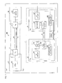
- Fig. 21 (a) is a perspective view showing an outer appearance of the light transmission module
- Fig. 21 (b) is a perspective view showing an inner appearance of a foldable portable telephone incorporating the light transmission module.
- Fig. 22 is a block diagram of a portion applied with the light transmission module in the foldable portable telephone incorporating the light transmission module.
- a light transmission module 100 is configured by a light transmission processing unit 2 with a light source drive circuit (light emission drive portion) and a light emitting portion (light emitting element; VCSEL (Vertical Cavity-Surface Emitting Laser)) connected to a master side board (main control board) 20 mounted with a CPU 29; a light reception processing unit 3 with a light receiving portion (light receiving element; PD (Photo-Diode) and a reception (amplifier) IC connected to a slave side board (application circuit board) 30 mounted with various types of applications such as an LCD (Liquid Crystal Display), an LCD driver 39 for drive controlling the LCD, and a camera module; and a light transmission path 4 for transmitting an optical signal by connecting the light transmission processing unit 2 and the light reception processing unit 3, such as an optical fiber or a light guide having high bendability.
- a light transmission processing unit 2 with a light source drive circuit (light emission drive portion) and a light emitting portion (light emitting element; VCSEL (Vertical Cavity-
- the light emission drive portion drives the light emission of the light emitting portion based on an electrical signal input from a main control board 20, and the light emitting portion irradiates a light incident surface of the light transmission path 4 with light.
- the light applied to the light incident surface of the light transmission path 4 is introduced into the light transmission path 4, and exit from a light exit surface of the light transmission path 4.
- the light exit from the light exit surface of the light transmission path 4 is received by the light receiving portion and converted to an electrical signal.
- the converted electrical signal is amplified to a desired value by an amplifier, and input to the LCD driver 39 and the like of the application circuit board 30.
- the use of such light transmission module enables high speed and large capacity data transmission from the main control board mounted in the portable telephone to the application circuit board.
- the light transmission module excels as a data transmission module.
- the light transmission module has an advantage in that large capacity data can be transmitted at high speed, but has a drawback in that the power consumption is large compared to the electrical transmission module for transmitting small capacity data at low speed.
- it is important to reduce the power consumption in the light transmission module, in particular, in a light transmission processing unit and a light reception processing unit.
- start and stop of the light transmission processing unit and the light reception processing unit are controlled according to the presence of data (transmitting data) transmitted between the units.
- data transmitting data
- Fig. 23 is a block diagram showing a schematic configuration of a portable telephone including a light transmission module showing a technique conventionally used in general for controlling start and stop of the light transmission processing unit and the light reception processing unit.
- start and stop of a light transmission processing unit (Tx) 2 and a light reception processing unit (Rx) 3 are individually controlled based on a control signal input from the CPU 29 and a CPU (not shown) on the data reception side.
- the CPU 29 on the data transmission side detects the presence of an input signal (data signal) to the light transmission processing unit 2 and controls the start and stop of the light transmission processing unit 2
- the CPU on the data reception side detects the presence of an output signal (data signal) from the light reception processing unit 3 and controls the start and stop of the light reception processing unit 3.
- Fig. 24 is a block diagram showing a schematic configuration of the light transmission module including a light reception circuit disclosed in patent document 1.
- such light transmission module includes a signal detection circuit 35 for determining whether or not the light receiving portion 31 received the optical signal, and a power supply controller 34 for controlling the power supply of an amplifier 32 and an I/F circuit 33 based on the detection result of the signal detection circuit 35.
- the power supply controller 34 stops the power supply of the amplifier 32 and the I/F circuit 33 if the light receiving portion 31 has not received the optical signal, and the power supply controller 34 starts the power supply of the amplifier 32 and the I/F circuit 33 if the light receiving portion 31 has received the optical signal.
- the power supply in the I/F circuit 21, the light emission drive portion 22, and the light emitting portion 23 can be controlled by the control signal input to the power supply controller 25 from the CPU (not shown) arranged outside.
- Patent document 1 Japanese Unexamined Patent Publication No. 2004-135188 (date of publication: April 30, 2004 ).
- the control of the start and the stop of the light transmission processing unit 2 and the light reception processing unit 3 are individually performed and synchronization thereof cannot be taken, and thus the light reception processing unit 3 might be operating in a reception standby (waiting) state even if the light transmission processing unit 2 is in the stopped state.
- the light reception processing unit 3 is in the operating state and the power in the light transmission processing unit 3 is wastefully consumed although data transmission is not performed. Therefore, the power consumption in a case where the light transmission module is in the standby state cannot be suppressed.
- the present invention provides a light transmission module including a light transmitting unit with a light emitting portion for outputting an optical signal corresponding to a data signal input as an electrical signal and a first power supply controller for controlling a drive power supply of the light emitting portion, a light transmission path for transmitting the optical signal introduced from the light transmitting unit, and a light receiving unit with a light receiving portion for receiving the optical signal output from the light transmission path and outputting an electrical signal corresponding to the optical signal and a second power supply controller for controlling a drive power supply of the light receiving portion;
- the light transmission module including: at last one electrical transmission path, connecting the light transmitting unit and the light receiving unit, for transmitting a control signal for controlling power supply to the light emitting portion and the light receiving portion to the first power supply controller and the second power supply controller; wherein the first power supply controller and the second power supply controller control the power supply to the light emitting portion and the light receiving portion based on the control signal input via the electrical transmission path.
- the light transmitting unit and the light receiving unit are connected by the light transmission path for transmitting the data signal and the electrical transmission path for transmitting the control signal.
- the control signal is input to the first power supply controller for controlling the drive power supply of the light emitting portion and the second power supply controller for controlling the drive power supply of the light receiving portion via the electrical transmission path, and the power supply to the light emitting portion and the light receiving portion is controlled based on the input control signal.
- the start and the stop of the light emitting portion and the light receiving portion can be controlled with the same control signal.
- the control signal commanding the stop of the power supply to the light emitting portion and the light receiving portion in the drive state is input to the first power supply controller and the second power supply controller, the power supply to the light emitting portion is stopped by the first power supply controller, and the power supply to the light receiving portion is stopped by the second power supply controller, whereby the light emitting portion and the light receiving portion make the transition from the drive state to the stopped state.
- the control signal commanding the start of the power supply to the light emitting portion and the light receiving portion in the stopped state is input to the first power supply controller and the second power supply controller, the power supply to the light emitting portion is started by the first power supply controller, and the power supply to the light receiving portion is started by the second power supply controller, whereby the light emitting portion and the light receiving portion make the transition from the stopped state to the drive state.
- a state in which either one of the light emitting portion and the light emitting portion is driven or stopped can be avoided since the power supply to the light emitting portion and the light receiving portion can be controlled with the same control signal. For instance, if the light emitting portion is in the stopped state, the light receiving portion is also in the stopped state. Thus, when the light emitting portion is in the stopped state, the power consumed by the light receiving portion can be reduced while waiting for the reception of the data signal transmitted from the light transmitting unit.
- the second power supply controller may control the power supply to the light receiving portion based on the control signal input via the electrical transmission path from the light transmitting unit.
- the control signal is transmitted in a direction same as a direction the data signal is transmitted.
- the control signal is input to the first power supply controller and the second power supply controller via the electrical transmission path of the light transmission module,
- the power supply to the light emitting portion and the light receiving portion can be stopped immediately after the transmission/reception process of the data signal in the light transmission module is completed, whereby wasteful power consumption can be suppressed.
- the first power supply controller may control the power supply to the light emitting portion based on the control signal input via the electrical transmission path from the light receiving unit.
- the control signal is transmitted in a direction opposite to a direction the data signal is transmitted.
- the image data (data signal) imaged by the camera is reception-processed by the CPU mounted on the main control board via the light transmission module.
- the control signal is then output from the CPU and input to the first power supply controller via the electrical transmission path.
- the light transmitting unit may further include a signal determination processing means for determining whether or not the data signal is input to the light transmitting unit and outputting the control signal to the first power supply controller and the second power supply controller based on the determination result; and the signal determination processing means may input a control signal for stopping the power supply to the light emitting portion and the light receiving portion to the first power supply controller and the second power supply controller via the electrical transmission path when determined that the data signal is not input to the light transmitting unit, and may input a control signal for starting the power supply to the light emitting portion and the light receiving portion to the first power supply controller and the second power supply controller via the electrical transmission path when determined that the data signal is input to the light transmitting unit.
- the control signal corresponding to the presence of the data signal input to the light transmitting unit is input to the first power supply controller and the second power supply controller.
- the power supply to the light emitting portion and the light receiving portion can be stopped immediately after determining that the data signal is not present, whereby wasteful consumption of the standby power can be suppressed.
- the light transmitting unit may receive the control signal from a transmission source side of the data signal and input the control signal to the first power supply controller and output the control signal to the electrical transmission path; and the light receiving unit may receive the control signal transmitted via the electrical transmission path, and input the control signal to the second power supply controller.
- the light transmission module when the control signal is input from the outside the light transmission module, the output control signal is input to the first power supply controller and the second power supply controller.
- the light transmission module since the presence of the input signal does not need to be determined in the light transmission module, the light transmission module itself can be miniaturized and the manufacturing cost can be reduced.
- the light transmission module of such configuration is suitable for a configuration in which the CPU etc. arranged exterior to the light transmission module determines the presence of the input signal to the light transmission module and performs the power supply control in the light transmission module.
- the light receiving unit may receive the control signal transmitted via the electrical transmission path, and input the control signal to the second power supply controller and outputs the control signal to the outside.
- control signal is transmitted by directly connecting the CPU mounted on the main control board and the application circuit in order to start or stop the power supply of the application circuit mounted on the application circuit board.
- the signal line for control signal transmission is thus necessary apart from the light transmission module, which led to increase in the wiring space.
- control signal is transmitted to the first power supply controller and the second power supply controller 4, and the application circuit mounted on the application circuit board using the electrical transmission path integrally configured with the light transmission module, and the power supply of the light transmission module and the application circuit is controlled.
- the wiring space thus can be saved, and the light transmission module can be applied to a smaller device.
- a high input impedance circuit may be arranged between a branched portion of the electrical transmission path connected to the light receiving unit and the electrical transmission path connected to the first power supply controller, and the first power supply controller on the electrical transmission path so that the first power supply controller may become high impedance when seen from the electrical transmission path.
- the transmitted high frequency signal (RF signal) is susceptible to other circuits, and bluntness occurs in the signal waveform.
- RF signal transmitted high frequency signal
- the input impedance of the first power supply controller that influences the signal waveform becomes high.
- the bluntness of the waveform of the high frequency signal thus can be prevented, and the control signal can be transmitted at high speed as a normal signal.
- a specific example of the high input impedance circuit is an inverter circuit that uses a MOS transistor for the input unit.
- the light transmitting unit may receive an input signal of the data signal and the control signal from respective transmission source via the same transmission path; the light transmitting unit may further include a signal separating means for separating the received input signal to one of the data signal and the control signal; and the signal separating means inputs the data signal to the light receiving portion while inputting the control signal to the first power supply controller and the second power supply controller via the electrical transmission path.
- the data signal and the control signal can be separated, and thus the transmission path for transmitting the data signal and the transmission path for transmitting the control signal connected to the light transmission module from the outside can be configured with the same transmission path.
- the number of transmission paths connected to the light transmission module can be reduced, whereby the light transmission module can be applied to a smaller device.
- the signal separating means may be configured by a high-pass filter and a low-pass filter; the high-pass filter is arranged on the transmission path connected to the light emitting portion, the input signal passed through the high-pass filter being input to the light emitting portion; the low-pass filter may be arranged on the electrical transmission path connected to the first power supply controller and the second power supply controller, the input signal passed through the low-pass filter being input to the first power supply controller and the second power supply controller via the electrical transmission path.
- the high input impedance circuit may be arranged between the branched portion and the low-pass filter, the branched portion being arranged between the electrical transmission path connected to the low-pass filter, on which the control signal is transmitted and the transmission path and the electrical transmission path connected to the light emitting portion, on which the data signal is transmitted, so that the electrical transmission path on which the control signal is transmitted may become high impedance when seen from the transmission path on which the data signal is transmitted.
- the data signal is the high frequency (RF) signal of greater than or equal to a several hundred MHz band
- the signal is less susceptible to the impedance of the electrical transmission path on the low speed side, and the waveform bluntness occurs.
- the high input impedance circuit is arranged such that the electrical transmission path becomes high impedance when seen from the data signal.
- the data signal of the RF band thus can be accurately transmitted to the light transmitting unit.
- a specific example of the high input impedance circuit is an inverter circuit that uses a MOS transistor for the input unit.
- the signal separating means may be configured by a first voltage comparison means for comparing a voltage level of the input signal and a first voltage value set in advance, and a second voltage comparison means for comparing the voltage level of the input signal and a second voltage value set in advance;
- the first comparison means may be arranged on the transmission path connected to the light emitting portion, the input signal being input to the light emitting portion if the first voltage value is in a range of change of the voltage level of the input signal;
- the second comparison means may be arranged on the electrical transmission path connected to the first power supply controller and the second power supply controller, the input signal being input to the first power supply controller and the second power supply controller via the electrical transmission path if the second voltage value is in a range of change of the voltage level of the input signal.
- the signal separating means may be configured by a frequency determining means for detecting a frequency of the input signal and comparing the detected frequency and a frequency set in advance, and a switching means for switching a transmission direction of the input signal by a switch based on the result determined by the frequency determining means; the switching means may switch the switch to transmit the input signal to the transmission path connected to the light emitting portion when the frequency determining means determines that the frequency of the input signal is greater than the frequency set in advance while switching the switch to transmit the input signal to the electrical transmission path connected to the first power supply controller and the second power supply controller when the frequency determining means determines that the frequency of the input signal is smaller than the frequency set in advance.
- the signal separating means may be configured by a voltage comparison means for detecting a voltage level of the input signal and comparing the detected voltage level and a voltage level set in advance, and a switching means for switching a transmission direction of the input signal by a switch based on the result compared by the voltage comparison means; the switching means may switch the switch to transmit the input signal to the transmission path connected to the light emitting portion when the voltage comparison means determines that the voltage level of the input signal is greater than the voltage level set in advance while switching the switch to transmit the input signal to the electrical transmission path connected to the first power supply controller and the second power supply controller when the voltage comparison means determines that the voltage level of the input signal is smaller than the voltage level set in advance.
- the electrical transmission path may include a flexible printed circuit board.
- the electrical transmission path may include a coaxial cable.
- a configuration of a foldable portable telephone including a main body with operation keys, a lid with a display screen, and a hinge for rotatably connecting the main body and the lid, where information (data) transmission between the main body and the lid is carried out through a light transmission module arranged in the hinge will be described by way of example.
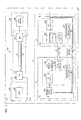
- Fig. 3(a) is a perspective view showing an outer appearance of a portable telephone 40 incorporating a light transmission module 1 of the first embodiment.
- Fig. 3(b) is a block diagram of a portion applied with the light transmission module 1 in the portable telephone 40 shown in Fig. 3(a).
- Fig. 3(c) is a perspective plan view of a hinge 41 (portion surrounded with a broken line) in Fig. 3(a) .
- the foldable portable telephone 40 is configured by a body unit 42, a hinge 41 arranged at one end of the body unit 42, and a lid 43 rotatably arranged with the hinge 41 as a shaft.
- the body unit 42 includes an operation key 44 for operating the portable telephone 40, and interiorly includes a main control board 20.
- the main control board 20 is mounted with a CPU 29 for comprehensively controlling each element (not shown) mounted on the main control board 20.
- the lid 43 exteriorly includes a display screen 45 and a camera (not shown) and interiorly includes an application circuit board 30.
- the application circuit board 30 is mounted with an LCD (Liquid Crystal Display) (not shown) for displaying images based on the image data transferred from the CPU 29, an LCD driver 39 for drive controlling the LCD, a camera module 39 including a camera for imaging a subject, and a camera drive portion for drive controlling the camera, and the like.
- LCD Liquid Crystal Display
- the light transmission module 1 connects the main control board 20 and the application circuit board 30, and carries out data transmission between the boards 20, 30.
- Specific examples of the data transmitted from the main control board 20 to the application circuit board 30 include drive signals for driving the LCD driver 39 and the camera module 39, and image data to be displayed on the LCD.
- Specific examples of the data transmitted from the application circuit board 30 to the main control board 20 include image data imaged by the camera.
- Fig. 4(a) is a block diagram of a portion applied with the light transmission module 1 in the portable telephone 40 incorporating the light transmission module 1 of the first embodiment
- Fig. 4(b) is a block diagram showing a schematic configuration of the light transmission module 1.
- the light transmission module 1 includes a light transmission processing unit (light transmitting unit; Tx) 2 connected to the main control board 20 mounting the CPU 29, a light reception processing unit (light receiving unit; Rx) 3 connected to the application circuit board 30 mounting the application circuit such as the LCD driver 39 and the camera module 39, a light transmission path 4 acting as an optical wiring for connecting the light transmission processing unit 2 and the light reception processing unit 3, and an electrical transmission path 5 acting as an electrical wiring for connecting the light transmission processing unit 2 and the light reception processing unit 3.
- a light transmission processing unit light transmitting unit; Tx
- Tx light transmitting unit
- Rx light receiving unit
- the application circuit board 30 mounting the application circuit such as the LCD driver 39 and the camera module 39
- a light transmission path 4 acting as an optical wiring for connecting the light transmission processing unit 2 and the light reception processing unit 3
- an electrical transmission path 5 acting as an electrical wiring for connecting the light transmission processing unit 2 and the light reception processing unit 3.
- the light transmission processing unit 2 includes an interface circuit (hereinafter referred to as I/F circuit) 21, a light emission drive portion 22, a light emitting portion 23, a signal determination processing portion (signal determination processing means) 24, and a power supply controller (first power supply controller) 25.
- I/F circuit interface circuit
- a light emission drive portion 22 a light emitting portion 23
- a signal determination processing portion signal determination processing means
- a power supply controller first power supply controller
- the I/F circuit 21 is a circuit for receiving signals having different voltage levels and frequency levels from the outside, and is arranged between the electrical wiring for the electrical signal externally input to the light transmission module 1 and the light emission drive portion 22. Although not illustrated, the I/F circuit 21 includes an electrical connecting portion with respect to the electrical wiring for transmitting the externally input electrical signal.
- the light emission drive portion 22 drives the light emission of the light emitting portion 23 based on the electrical signal externally input to the light transmission module 1 through the I/F circuit 21.
- the light emission drive portion 22 is configured by a light emission drive IC (Integrated Circuit), and the like.
- the light emitting portion 23 emits light based on the drive control by the light emission drive portion 22.
- the light emitting portion 23 is configured by a light emitting element such as a VCSEL (Vertical Cavity-Surface Emitting Laser).
- the light incident side end of the light transmission path 4 is irradiated with the light emitted from the light emitting portion 23 as an optical signal.
- the signal determination processing portion 24 determines the presence of the signal output from the main control board 20, and outputs a control signal corresponding to the determination result. The details of the signal determination processing portion 24 will be hereinafter described.
- the power supply controller 25 comprehensively controls the power supply of each portion configuring the light transmission processing unit 2 based on the control signal output from the signal determination processing portion 24. Specifically, the power supply controller 25 supplies power to the I/F circuit 21, the light emission drive portion 22, and the light emitting portion 23 to drive them, while shielding the supply of power to the I/F circuit 21, the light emission drive portion 22, and the light emitting portion 2 and stops the same based on the control signal.
- the light transmission processing unit 2 converts the electrical signal input to the light transmission processing unit 2 to the optical signal corresponding to the electrical signal and outputs the optical signal to the light transmission path 4, and has the power supply of each portion configuring the interior thereof controlled by the power supply controller 25.
- the light reception processing unit 3 includes a light receiving portion 31, an amplifier 32, an I/F circuit 33, and a power supply controller 34.
- the light receiving portion 31 receives the light serving as the optical signal exit from the light exit side end of the light transmission path 4, and outputs the electrical signal by photoelectric conversion.
- the light receiving portion 31 is configured by a light receiving element such as a PD (Photo-Diode).
- the amplifier 32 amplifies the electrical signal output from the light receiving portion 31 to a desired value, and outputs the desired value to the outside.
- the amplifier 32 is configured by an amplification IC, and the like.
- the I/F circuit 33 is a circuit for outputting the electrical signal amplified by the amplifier 32 to the outside of the light transmission module 1, and is arranged between the amplifier 32 and the electrical wiring connecting to the outside of the light transmission module 1. Although not illustrated, the I/F circuit 33 includes an electrical connecting portion with respect to the electrical wiring for transmitting the input electrical signal to the outside.
- the power supply controller 34 receives the control signal output from the signal determination processing portion 24 of the light transmission processing unit 2 through the electrical transmission path 5, to be hereinafter described, and comprehensively controls the power supply of each portion configuring the light reception processing unit 3 based on the control signal. Specifically, the power supply controller 34 supplies power to the light receiving portion 31, the amplifier 32, and the I/F circuit 33 to drive them, while shielding the supply of power to the light receiving portion 31, the amplifier 32, and the I/F circuit 33 and stops the same.
- the light reception processing unit 3 thus receives the optical signal output from the light transmission path 4, converts the same to the electrical signal corresponding to the optical signal, amplifies the same to a desired signal value and outputs the desired value to the outside, and has the power supply of each portion configuring the interior thereof controlled by the power supply controller 34.
- the light transmission path 4 is a medium for transmitting the optical signal serving as data signal emitted from the light emitting portion 23 to the light receiving portion 31, and the electrical transmission path 5 is a medium for transmitting the electrical signal serving as the control signal output from the light transmission processing unit 2 to the light reception processing unit 3.
- the details of the light transmission path 4 and the electrical transmission path 5 will be hereinafter described in detail.
- Fig. 5(a) shows a side view of the light transmission path 4.
- the light transmission path 4 has a configuration including a column-shaped core 4a having a light transmission direction as an axis, and a clad 4b arranged to surround the periphery of the core 4a.
- the core 4a and the clad 4b are made of materials having translucency, where the index of refraction of the core 4a is higher than the index of refraction of the clad 4b.
- the optical signal that entered the core 4a is transmitted in the light transmission direction by being totally reflected repeatedly inside the core 4a.
- Glass, plastic, or the like may be used for the material for forming the core 4a and the clad 4b, but resin material of acryl series, epoxy series, urethane series, silicone series and the like is preferably used to form the light transmission path 4 having sufficient flexibility.
- the clad 4b may be made of gas such as air. Furthermore, similar effects can be obtained even if the clad 4b is used under a liquid atmosphere having smaller index of refraction than the core 4a.
- Fig. 5(b) schematically shows a state of light transmission in the light transmission path 4.
- the light transmission path 4 is configured by a column-shaped member having flexibility.
- a light incident surface 4A is provided on the light incident side end of the light transmission path 4, and a light exit surface 4B is provided on the light exit side end.
- the light emitted from the light emitting portion 23 enters the light incident side end of the light transmission path 4 from a direction perpendicular to or substantially perpendicular to the light transmission direction of the light transmission path 4.
- the incident light is introduced into the light transmission path 4 by being reflected at the light incident surface 4A and advances through the core 4a.
- the light that advanced through the light transmission path 4 and reached the light exit side end is reflected at the light exit surface 4B and exit in a direction perpendicular to or substantially perpendicular to the light transmission direction of the light transmission path 4.
- the light receiving portion 31 is irradiated with the exit light, and the exit light is photoelectric converted in the light receiving portion 31.
- the light emitting portion 23 serving as a light source can be arranged in a direction perpendicular to or substantially perpendicular to the light transmission direction in the light transmission path 4.
- the light emitting portion 23 is installed between the light transmission path 4 and the substrate surface so as to emit light in a normal direction of the substrate surface.
- Such configuration facilitates mounting and enables further miniaturization in configuration than the configuration of installing the light emitting portion 23 so as to emit light parallel to the substrate surface.
- the general configuration of the light emitting portion 23 is such that a size in a direction perpendicular to a direction of emitting light is larger than the size in a direction of emitting light.
- application can be made to a configuration of using a plane mounting light emitting element in which the electrode and the light emitting portion 23 are in the same plane.
- the light transmission path 4 shown in the figure has a configuration in which the light incident surface 4A and the light exit surface 4B are inclined, as described above, but the light transmission path 4 in the present embodiment may have a configuration in which both end surfaces are orthogonal to the light transmission direction.
- the outer shape of the light transmission path 4 may be formed to a solid rectangular shape.
- the signal determination processing portion 24 is connected to the I/F circuit 21, and determines the presence of the electrical signal (input signal) externally input to the light transmission processing unit 2.
- the signal determination processing portion 24 outputs a signal (stop signal) commanding the stop of power supply to each portion to the power supply controller 25 of the light transmission processing unit 2 and the power supply controller 34 of the light reception processing unit 3 if determined that the input signal is not present, while outputting a signal (start signal) commanding the start of power supply to each portion to the power supply controllers 25, 34 if determined that the input signal is present.
- the signal determination processing portion 24 thus determines the presence of the input signal with respect to the light transmission module 1, and outputs the control signal, that is, a signal indicating start command or stop command based on the determination result.
- a method the signal determination processing portion 24 determines the presence of the input signal in the light transmission processing unit 2 will be described below using two methods by way of example.
- the first method is a method of reading change of "0" or "1” of the digital input signal. Specifically, the presence of the input signal is determined if "0" or “1" of the input signal does not change during the preset time, where determination is made that the input signal is not present if the input signal indicating "0” does not change during the preset time, and determination is made that the input signal is present if the input signal indicating "0" changed to "1" before elapse of the preset time. For instance, determination is made that the input signal is present if the input signal indicating "1” does not change during the preset time, and determination is made that the input signal is not present if the input signal indicating "1” changed to "0” before elapse of the preset time.
- the second method is a method of reading voltage change of the input signal. Specifically, the presence of the input signal is determined by whether or not the voltage of the input signal is within the preset voltage range, where determination is made that the input signal is present if the voltage of the input signal is within the preset voltage range, and determination is made that the input signal is not present if the voltage of the input signal is outside the preset voltage range.
- the signal determination processing portion 24 After determining the presence of the input signal through the above illustrated methods, the signal determination processing portion 24 outputs the control signal, specifically, the signal of "0" indicating the stop command or the signal of "1" indicating the start command to the power supply controllers 25, 34 in the light transmission processing unit 2 and the light reception processing unit 3, respectively.
- the respective power supply controllers 25, 34 controls the power supply of each portion of the light transmission processing unit 2 and the light reception processing unit 3 based on the control signal received from the signal discrimination processing unit 24.
- the electrical transmission path 5 is arranged parallel to the light transmission path 4, and connects the light transmission processing unit 2 and the light reception processing unit 3 to transmit the control signal output from the light transmission processing unit 2 to the light reception processing unit 3. Specifically, as shown in Fig. 4(b) , the electrical light transmission path 5 connects the signal determination processing portion 24 and the power supply controller 25 of the light transmission processing unit 2 to the power supply controller 34 of the light reception processing unit 3, and transmits the control signal output from the signal determination processing portion 24 to the respective power supply controllers 25, 34.
- the electrical transmission path 5 is specifically configured by a flexible printed circuit board (FPC), coaxial cable, lead frame, and the like.
- Fig. 6 is a perspective view showing a schematic configuration of the light transmission module 1 when the electrical transmission path 5 is configured by the FPC.
- the light transmission module 1 thus can be applied to a small electronic device such as a portable telephone by forming the light transmission path 4 and the electrical transmission path 5 with a flexible wiring.
- the electrical transmission path 5 shown in Fig. 4(b) is configured by one signal line, but is not limited thereto, and may be formed by two or more signal lines.
- Fig. 7 is a block diagram showing a schematic configuration of the light transmission module 1 when the electrical transmission path 5 is configured by two signal lines. As shown in the figure, the two signal lines respectively connect the light transmission processing unit 2 and the light reception processing unit 3, and transmit the control signal to the respective power supply controllers 25, 34.
- the power state (power mode) in the light transmission processing unit 2 and the light reception processing unit 3 can be controlled to various states.
- each electrical transmission path 5 can be controlled to the power mode corresponding to the combination of transmitting signal values ("0" or "1"), that is, four combinations of "00", "01", “10", "11".
- the setting and changes can be made to different power modes such as a stop mode in which the power of the light transmission processing unit 2 and the light reception processing unit 3 is completely shielded, a standby mode in which the power of the light transmission processing unit 2 and the light reception processing unit 3 is not completely shielded and a very small amount of standby power is supplied to enable high speed response process in time of activating, and a normal drive mode in which the power of the light transmission processing unit 2 and the light reception processing unit 3 is constantly supplied.
- the setting of the correspondence relationship of the control signal and the power mode is realized by a table (not shown).
- control is made to 2 n power modes by configuring the electrical transmission path 5 with n signal lines.
- a plurality of power modes can be controlled without using digital values of "0" and "1” by using one of the two signal lines as a clock signal line and the other signal line as a data signal line, and transmitting a command of 8 bits, 16 bits, or the like as a data signal.
- the power supply controllers 25, 34 in the light transmission processing unit 2 and the light reception processing unit 3 that received the control signal via the electrical transmission path 5 change the light transmission processing unit 2 and the light reception processing unit 3 to the power mode corresponding to the control signal. For instance, when each of the power supply controllers 25, 34 receives the stop signal from the signal determination processing portion 24, the power supply of the I/F circuit 21, the light emission drive portion 22 and the light emitting portion 23 driven in the light transmission processing unit 2, and the light receiving portion 31, the amplifier 32, and the I/F circuit 33 driven in the light reception processing unit 3 is shielded to change from the drive mode to the stop mode.
- the light transmission module 1 of the first embodiment has a configuration of controlling the power supply of the light transmission processing unit 2 and the light reception processing unit 3 based on the control signal output from the light transmission processing unit 2 or the data transmitting side.
- the power of the light reception processing unit 3 can be completely turned OFF if the data signal is not input to the light transmission module 1, whereby the power consumption in time of standby can be reduced compared to the conventional configuration.
- the power supply in the light transmission processing unit 2 and the light reception processing unit 3 is controlled using the same signal line (electrical transmission path 5), the start/stop of both units can be simultaneously controlled, and wasteful power consumption due to the influence of time lag can be reduced.
- Fig. 8(a) is a block diagram of a portion applied with the light transmission module 1 in the portable telephone 40 incorporating the light transmission module 1 serving as the variant 1-1 in the first embodiment
- Fig. 8B is a block diagram showing a schematic configuration of the light transmission module 1.
- the light transmission processing unit 2 and the light reception processing unit 3 of the light transmission module 4 shown in Fig. 4(a) and Fig. 4(b) have opposite configurations. That is, the light transmission processing unit 2 and the application circuit such as the camera module 39 are connected, and the light reception processing unit 3 and the CPU 29 are connected.
- the image data (data signal) imaged by the camera (camera module 39) is input to the I/F circuit 21 of the light transmission processing unit 2.
- the signal determination processing portion 24 determines that the input signal is present, and outputs a signal (start signal) commanding the start of the power supply to each unit configuring the light transmission module 1 to the power supply controllers 25, 34.
- the power supply controllers 25, 34 that received the start signal supply power to each unit and start the same.
- the image data After being transmitted by the light reception processing unit 3 through the light transmission path 4, the image data is stored in the memory (not shown) by the process of the CPU 29.
- the signal determination processing portion 24 When determining that the input signal to be received next at the I/F circuit 21 is not present, the signal determination processing portion 24 outputs a signal (stop signal) commanding the stop of the power supply to each unit to the power supply controllers 25, 34.
- the power supply controllers 25, 34 that received the stop signal shield the power supply to each unit and change from the drive mode to the stop mode.
- the light transmission processing unit 2 has a configuration of receiving the data signal from the application circuit board 30 side mounted with the camera module 39, and outputting the control signal based on the received data signal.
- the flow of data signals and control signals in the light transmission module 1 in the variant 1-1 is configured opposite to the flow of data signals and control signals in the light transmission module 1 shown in Fig. 4(a) and Fig. 4(b) .
- the light transmission module that can perform bi-directional communication can be realized by arranging the light transmission module shown in the figures as in Fig. 3(b) .
- Fig. 9(a) is a block diagram of a portion applied with a light transmission module 10 in the portable telephone 40 incorporating the light transmission module 10 of the second embodiment
- Fig. 9(b) is a block diagram showing a schematic configuration of the light transmission module 10.
- the signal determination processing portion 24 arranged in the light transmission processing unit 2 determines the presence of the input signal to the light transmission module 1, and outputs the control signal corresponding to the determination result to the power supply controller 25 and the power supply controller 34, but the control signal is received from outside the light transmission module 10 in the second embodiment.
- the power supply controller 25 of the light transmission processing unit 2 and the power supply controller 34 of the light reception processing unit 3 receive the control signal of the stop signal or the start signal generated outside, and control the light transmission processing unit 2 and the light reception processing unit 3 based on the received control signal.
- the light transmission processing unit 2 includes, apart from the input terminal (data signal input terminal) for receiving the data signal, an input signal (control signal input terminal) for receiving the control signal from the outside such as from the CPU 29 mounted on the main control board 20.
- the light transmission processing unit 2 and the CPU 29 are connected by the transmission path for data signal transmission and the transmission path for control signal transmission.
- the electrical transmission path 5 for transmitting the control signal is connected to the control signal input terminal, and the electrical transmission path 5 is connected to the respective power supply controllers 25, 34 of the light transmission processing unit 2 and the light reception processing unit 3.
- the power of the light transmission processing unit 2 and the light reception processing unit 3 can be completely turned OFF when data is not input to the light transmission module 10, similar to the first embodiment, and thus the power consumption in time of standby can be reduced compared to the conventional configuration. Furthermore, since the power supply in the light transmission processing unit 2 and the light reception processing unit 3 is controlled using the same signal line (electrical transmission path 5) based on the control signal input to the light transmission module 10, the start/stop of both units can be simultaneously controlled, and wasteful power consumption due to the influence of time lag can be reduced.
- the light transmission module 10 of the second embodiment is suitable when the CPU 29 arranged exterior to the light transmission module 10 determines the presence of the input signal to the light transmission module 10 and performs the power supply control in the light transmission module 10.
- the light transmission module 10 includes, at least, each configuring member for transmitting the optical signal, the electrical transmission path 5 for transmitting the control signal, and the power supply controllers 25, 34 for controlling the power supply based on the control signal.
- the miniaturization of the light transmission module 10 itself can be achieved, and the manufacturing cost can be reduced.
- Fig. 10(a) is a block diagram of a portion applied with the light transmission module 10 in the portable telephone 40 incorporating the light transmission module serving as the variant 2-1
- Fig. 10(b) is a block diagram showing a schematic configuration of the light transmission module 10.
- the light transmission processing unit 2 and the light reception processing unit 3 of the light transmission module 10 shown in Fig. 9(b) have opposite configurations. That is, the light transmission processing unit 2 and the application circuit such as the camera module 39 are connected, and the light reception processing unit 3 and the CPU 29 are connected.
- the image data (data signal) imaged by the camera (camera module 39) is transmitted from the light transmission processing unit 2 to the light reception processing unit 3 via the light transmission path 4.
- the image data received by the light reception processing unit 3 is stored in the memory (not shown) by the process of the CPU 29.
- the CPU 29 outputs the control signal (e.g., stop signal) at the time point the image data transmitted from the main control board 20 is detected.
- the stop signal is input to the power supply controller 34 of the light reception processing unit 3 and input to the power supply controller 25 of the light transmission processing unit 2 via the electrical transmission path 5.
- the power supply controller 25 shields the power supply of the light receiving portion 31, the amplifier 32, and the I/F circuit 33 driven in the light reception processing unit 3 and the I/F circuit 21, the light emission drive portion 22, and the light emitting portion 23 driven in the light transmission processing unit 2, and changes from the drive mode to the stop mode.
- the power supply controller 25 of the light transmission processing unit 2 receives the control signal output from the light reception processing unit 3 that receives the data signal, and controls the power supply of the light reception processing unit 2.
- the light transmission module that can perform bi-directional communication can be realized by being simultaneously used with the light transmission module 10 shown in Fig. 9(b) .
- Fig. 11(a) is a block diagram of a portion applied with the light transmission module 10 in the portable telephone 40 incorporating the light transmission module serving as the variant 2-2
- Fig. 11 (b) is a block diagram showing a schematic configuration of the light transmission module 10.
- the electrical transmission path 5 in the light transmission module 10 is connected to the CPU 29 mounted on the main control board 30, the power supply controller 25 of the light transmission processing unit 2, and the power supply controller 34 of the light reception processing unit 3 through the control signal input terminal, but in the variant 2-2, the electrical transmission path 5 is further connected to the application circuit such as the LCD driver 39 mounted on the application circuit board 30.
- control signal is transmitted by directly connecting the CPU mounted on the main control board and the application circuit to start or stop the power supply of the application circuit mounted on the application circuit board.
- a control signal transmission signal line needed to be arranged separate from the light transmission module, which led to increase in wiring space.
- the control signal output from the CPU 29 of the main control board 20 is simultaneously transmitted to the power supply controllers 25, 34 of the light transmission module 10 and the application circuit mounted on the application circuit board 30 using the electrical transmission path 5 that transmits the control signal for controlling the power supply, thereby simultaneously controlling the power supply of the light transmission module 10 and the application circuit.
- the wiring space thus can be saved and the light transmission module 10 can be applied to a smaller device.
- the signal can be input/output to and from the outside at both end sides of the light transmission module 10, that is, the main control board 20 and the application circuit board 30, and thus the control signal output from the camera module 39 mounted on the application circuit board 30 can be transmitted to the CPU 29 of the main control board 20.
- Fig. 12(a) is a block diagram showing a schematic configuration of the light transmission module 10 serving as the variant 2-3
- Fig. 12(b) is a circuit diagram showing a configuration of a high input impedance circuit 26 (circled portion).
- a high input impedance circuit 26 is arranged between a branched portion 5a and the power supply controller 25, the branched portion 5a being arranged between the light reception processing unit 3 and the power supply controller 25, on the electrical transmission path 5 such that the power supply controller 25 of the light transmission processing unit 2 becomes high impedance when seen from the electrical transmission path 5.
- the transmitted high frequency signal (RF signal) is susceptible to other circuits, and bluntness occurs in the signal waveform.
- RF signal transmitted high frequency signal
- the high input impedance circuit 26 is arranged such that the input impedance of the circuit that influences the signal waveform i.e., the power supply controller 25 herein becomes high. The bluntness of the waveform of the high frequency signal is thereby prevented, and the control signal can be transmitted at high speed as a normal signal.
- a specific example of the high input impedance circuit 26 is an inverter circuit that uses a MOS transistor for the input unit.
- Fig. 13(a) is a block diagram of a portion applied with the light transmission module 10 in the portable telephone 40 incorporating the light transmission module 10 serving as the variant 2-4
- Fig. 13(b) is a block diagram showing a schematic configuration of the light transmission module 10.
- the light transmission module 10 of the variant 2-4 the CPU 29 and the light transmission processing unit 2 are connected with one transmission path, and the data signals and the control signals are input to the light transmission processing unit 2 via the relevant transmission path.
- the light transmission module 10 includes a signal separator 27 for separating the data signal and the control signal, where the data signal separated by the signal separator 27 is input to the I/F circuit 21 of the light transmission processing unit 2 while the control signal separated by the signal separator 27 is input to the power supply controller 25 of the light transmission processing unit 2 and the power supply controller 34 of the light reception processing unit 3 via the electrical transmission path 5.
- the electrical transmission path 5 may be configured to be connected only to the power supply controller 34 of the light reception processing unit 3 so as to control the power supply of the light reception processing unit 3, or may be configured to be connected to the transmission path for transmitting the data signal output from the light reception processing unit 3, as shown in Fig. 13(b) .
- the control signal output from the CPU 29 can be input to the LCD driver 39 and the like of the application circuit board 30.
- the effects similar to the variant 2-2 are thereby obtained and the number of transmission paths to be connected to the light transmission module 10 can be reduced, whereby the light transmission module 10 can be applied to a smaller device.
- a configuration example 1 of the signal separator 27 is a configuration of separating the data signal and the control signal based on the value of the frequency of the signal (hereinafter referred to as input signal) input to the light transmission module 10.
- Fig. 14 is a block diagram showing a schematic configuration of the light transmission module 10 serving as the configuration example 1.
- the signal separator 27 is configured by a high-pass filter (hereinafter referred to as HPF) 271 a and a low-pass filter (hereinafter referred to as LPF) 271 b.
- HPF high-pass filter
- LPF low-pass filter
- the HPF 271 a is arranged on the transmission path between the branched portion 5b of the transmission path for data signal transmission and the transmission path for control signal transmission, and the I/F circuit 21 of the light transmission processing unit 2, and the LPF 271 b is arranged on the electrical transmission path 5 between the branched portion 5b and the power supply controller 25 of the light transmission processing unit 2.
- the data signal of high frequency (high speed) can be transmitted to the I/F circuit 21 via the HPF 271 a under normal circumstances, and the control signal of low frequency (low speed) can be transmitted to the power supply controller 25 and the light reception processing unit 3 via the LPF 271 b under normal circumstances.
- the data signal is a high frequency (RF) signal of a several hundred MHz band, it is susceptible to the impedance of the electrical transmission path 5 on the low speed side, and waveform bluntness occurs.
- the light transmission module 10 of the configuration example 1 may further include the high input impedance circuit 26 between the branched portion 5b and the LPF 271 b so that the electrical transmission path 5 seen from the data signal becomes high impedance, similar to the variant 2-3.
- the data signal of RF band thus can be accurately transmitted to the light transmission processing unit 2.
- a specific example of the high input impedance circuit 26 is an inverter circuit that uses a MOS transistor for the input unit.
- a configuration example 2 of the signal separator 27 is a configuration of separating the data signal and the control signal based on the voltage level of the input signal. This configuration is effective when the voltage level of the data signal and the voltage level of the control signal differ, as shown in Fig. 16(a).
- Fig. 16(a) is a block diagram showing a schematic configuration of the light transmission module 10 serving as the configuration example 2. As shown in Fig. 16(a) , the signal separator 27 is configured by a first voltage comparison circuit (first voltage comparison means) 272a and a second voltage comparison circuit (second voltage comparison means) 272b each having different threshold values.
- Fig. 16(c) is a circuit diagram of each of the voltage comparison circuits 272a, 272b, and
- Fig. 16(d) is a view showing a waveform of the signal separated by the voltage comparison circuits 272a, 272b.
- the threshold value is set high (Th_H; first voltage value) in the first voltage comparison circuit 272a so that the input signal of high voltage level is transmitted to the I/F circuit 21 on the downstream side, and the threshold value is set low (Th_L; second voltage value) in the second voltage comparison circuit 272b so that the input signal of low voltage level is transmitted to the power supply controller 25 and the light transmission processing unit 3 on the downstream side.
- the input signal is assumed as the data signal and transmitted to the I/F circuit 21 when the threshold value (Th_H) is in the range of change of the voltage level of the input signal, whereas the input signal is assumed as the control signal and transmitted to the power supply controller 25 and the light reception processing unit 3 when the threshold value (Th_L) is in the range of change of the voltage level of the input signal.
- a configuration example 3 of the signal separator 27 is a configuration of separating the data signal and the control signal based on the value of the frequency of the input signal, similar to the configuration example 1.
- Fig. 17 is a block diagram showing a schematic configuration of the light transmission module 10 serving as the configuration example 3. As shown in the figure, the signal separator 27 is configured by a frequency determining portion 273 and a switching portion 274.
- the frequency determining portion 273 determines the frequency of the input signal. Specifically, the frequency determining portion 273 determines whether or not the value of the frequency of the input signal is greater than a value set in advance, and outputs the determination result to the switching portion 274.
- the switching portion 274 switches the transmission path for data signal transmission and the transmission path for control signal transmission by a switch based on the determination result received from the frequency determining portion 273.
- the data signal of high frequency can be transmitted to the I/F circuit 21 under normal circumstances, and the control signal of low frequency (low speed) can be transmitted to the power supply controller 25 and the light reception processing unit 3 under normal circumstances.
- a configuration example 4 of the signal separator 27 is a configuration of separating the data signal and the control signal based on the voltage level of the input signal. This configuration is effective when the voltage level of the data signal and the voltage level of the control signal differ, as shown in Fig. 18(a) , similar to the configuration example 2.
- Fig. 18(a) is a block diagram showing a schematic configuration of the light transmission module 10 serving as the configuration example 4. As shown in Fig. 18(a) , the signal separator 27 is configured by a voltage comparison circuit (voltage comparison means) 275 and the switching portion 274.
- the voltage comparison circuit 275 determines the voltage level of the input signal. Specifically, the voltage comparison circuit 275 determines whether or not the voltage level of the input signal is greater than the threshold value (Th voltage) set in advance shown in Fig. 18(b) , and outputs the determination result to the switching portion 274.
- the switching portion 274 switches the transmission path for data signal transmission and the transmission path for control signal transmission based on the determination result received from the frequency determining portion 273.
- the input signal (data signal) can be transmitted to the I/F circuit 21 if the input signal is greater than the threshold value, and the input signal (control signal) can be transmitted to the power supply controller 25 and the light reception processing unit 3 if the input signal is smaller than the threshold value.
- the light transmission module of the present invention has a configuration in which the power supply controller 25 of the light transmission processing unit 2 and the power supply controller 34 of the light reception processing unit 3 control the power supply of each portion configuring the light transmission processing unit 2 and the light reception processing unit 3 based on the received control signal.
- the control signal is output from the light transmission processing unit 2 (or light reception processing unit 3) and is input to the power supply controller 34 (or the power supply controller 25) of the light reception processing unit 3 (or light transmission processing unit 2), as shown in Fig. 1(a) and Fig. 1(b) ( Fig. 10(a) and Fig. 10(b) ).
- the light transmission module of the present invention merely needs to have a configuration in which the light transmission processing unit 2 includes the light emitting portion 23 and the power supply controller 25 for controlling the power supply of the light emitting portion 23, and the light reception processing unit 3 includes the light receiving portion 31, the amplifier 32 and the power supply controller 34 for controlling the power supply thereof, where the I/F circuit 21, the light emission drive portion 22, and the I/F circuit 33 may be arranged exterior to the light transmission module.
- the light transmission module of the present embodiment can be applied to the following application examples.
- an example of being applied to the portable telephone 40 has been described as a first application example, but the light transmission module of the present invention is not limited thereto, and may be applied to a hinge and the like of a foldable electronic device such as a foldable PHS (Personal Handyphone System), a foldable PDA (Personal Digital Assistant), a foldable notebook computer and the like.
- a foldable electronic device such as a foldable PHS (Personal Handyphone System), a foldable PDA (Personal Digital Assistant), a foldable notebook computer and the like.
- a high speed and large capacity communication can be realized in a limited space by applying the light transmission module to such foldable electronic devices. Therefore, it is particularly suitable in devices where high speed and large capacity data communication is necessary and miniaturization is demanded such as the foldable liquid crystal display.
- the light transmission modules 1, 10 of the present invention can be applied to a device including a drive portion such as such as a printer head in a printing device (electronic device) and a reading unit in a hard disc recording and reproducing device.
- Figs. 19A to 19C show an example in which the light transmission modules 1,10 are applied to a printing device 50.
- Fig. 19(a) is a perspective view showing an outer appearance of the printing device 50.
- the printing device 50 includes a printer head 51 for performing printing on a paper 52 while moving in a width direction of a paper 52, where one end of the light transmission modules 1, 10 is connected to the printer head 51.
- Fig. 19(b) is a block diagram of a portion where the light transmission modules 1, 10 are applied in the printing device 50. As shown in the figure, one end of the light transmission modules 1, 10 is connected to the printer head 51, and the other end is connected to a body side substrate in the printing device 50.
- the body side substrate includes a control means etc. for controlling the operation of each unit of the printing device 50, and the like.
- Fig. 19(c) and Fig. 19(d) are perspective views showing a curved state of the light transmission path 4 when the printer head 51 is moved (driven) in the printing device 50.
- the curved state of the light transmission path 4 changes by the drive of the printer head 51 and each position of the light transmission path 4 is repeatedly curved.
- the light transmission modules 1, 10 according to the present embodiment are suited for such drive portion. High speed and large capacity communication using the drive portion can be realized by applying the light transmission modules 1, 10 to such drive portions.
- Fig. 20 shows an example in which the light transmission path 4 is applied to a hard disc recording and reproducing device 60.
- the hard disc recording and reproducing device 60 includes a disc (hard disc) 61, a head (read/write head) 62, a substrate introducing portion 63, a drive portion (drive motor) 64, and the light transmission modules 1, 10.
- the drive portion 64 drives the head 62 along a radial direction of the disc 61.
- the head 62 reads the information recorded on the disc 61 and writes information to the disc 61.
- the head 62 is connected to the substrate introducing portion 63 by way of the light transmission modules 1, 10, and propagates the information read from the disc 61 to the substrate introducing portion 63 as an optical signal and receives the optical signal of the information to write to the disc 61 propagated from the substrate introducing portion 63.
- the light transmission module in the present invention has a configuration of connecting the light transmitting unit and the light receiving unit, and including at least one electrical transmission path for transmitting the control signal for controlling the power supply to the light emitting portion and the light receiving portion to the first power supply controller and the second power supply controller, in which the first power supply controller and the second power supply controller control the power supply to the light emitting portion and the light receiving portion based on the control signal input via the electrical transmission path.
- the start/stop of the light emitting portion and the light receiving portion thus can be controlled by the same control signal. Therefore, a light transmission module capable of reducing the power consumption in time of standby with a simple configuration is thereby obtained.
- the light transmission module according to the present invention is applicable to the light communication path between various types of devices, and is also applicable to a flexible optical wiring serving as an in-device wiring mounted in a small and thin commercial-off-the-shelf device.
Landscapes
- Physics & Mathematics (AREA)
- Electromagnetism (AREA)
- Engineering & Computer Science (AREA)
- Computer Networks & Wireless Communication (AREA)
- Signal Processing (AREA)
- Optical Communication System (AREA)
Applications Claiming Priority (2)
| Application Number | Priority Date | Filing Date | Title |
|---|---|---|---|
| JP2007099917 | 2007-04-05 | ||
| PCT/JP2008/056670 WO2008126755A1 (fr) | 2007-04-05 | 2008-04-03 | Module de transmission optique et dispositif électronique |
Publications (2)
| Publication Number | Publication Date |
|---|---|
| EP2166680A1 true EP2166680A1 (fr) | 2010-03-24 |
| EP2166680A4 EP2166680A4 (fr) | 2013-01-23 |
Family
ID=39863855
Family Applications (1)
| Application Number | Title | Priority Date | Filing Date |
|---|---|---|---|
| EP08739777A Withdrawn EP2166680A4 (fr) | 2007-04-05 | 2008-04-03 | Module de transmission optique et dispositif électronique |
Country Status (6)
| Country | Link |
|---|---|
| US (1) | US8380062B2 (fr) |
| EP (1) | EP2166680A4 (fr) |
| JP (1) | JP4968330B2 (fr) |
| KR (3) | KR101173814B1 (fr) |
| CN (1) | CN101715632A (fr) |
| WO (1) | WO2008126755A1 (fr) |
Cited By (2)
| Publication number | Priority date | Publication date | Assignee | Title |
|---|---|---|---|---|
| EP2524270A4 (fr) * | 2010-01-11 | 2016-06-01 | Hewlett Packard Development Co | Système comprenant un circuit de commande pour une signalisation électrique et une signalisation optique |
| WO2018232261A3 (fr) * | 2017-06-16 | 2019-01-24 | Apple Inc. | Capteur d'image ayant des capacités de communication optique |
Families Citing this family (18)
| Publication number | Priority date | Publication date | Assignee | Title |
|---|---|---|---|---|
| JP5235490B2 (ja) * | 2008-05-13 | 2013-07-10 | キヤノン株式会社 | 通信システム及び通信装置 |
| JP5136374B2 (ja) * | 2008-11-21 | 2013-02-06 | オムロン株式会社 | 光伝送システム及びそれを備えた電子機器 |
| JP4920723B2 (ja) * | 2009-05-14 | 2012-04-18 | シャープ株式会社 | 画像表示装置用伝送システムおよび電子機器 |
| US20110142453A1 (en) * | 2009-12-11 | 2011-06-16 | Electronics And Telecommunications Research Institute | Optical transceiver and method for controlling the same |
| JP5417151B2 (ja) * | 2009-12-18 | 2014-02-12 | 株式会社東芝 | 光配線ケーブルと光配線ケーブルの電源制御方法 |
| US8458378B2 (en) * | 2009-12-25 | 2013-06-04 | Kabushiki Kaisha Toshiba | Cable |
| JP4883211B1 (ja) * | 2010-09-17 | 2012-02-22 | オムロン株式会社 | 伝送システムおよび電子機器 |
| US9363173B2 (en) * | 2010-10-28 | 2016-06-07 | Compass Electro Optical Systems Ltd. | Router and switch architecture |
| US8995830B2 (en) * | 2011-02-25 | 2015-03-31 | Mitsubishi Electric Corporation | Communication system, optical network unit, optical line terminal, control device, and communication control method |
| KR20120128847A (ko) * | 2011-05-18 | 2012-11-28 | 한국전자통신연구원 | 레인별로 전원을 제어하기 위한 광 트랜시버 모듈 |
| TWI534775B (zh) * | 2012-03-08 | 2016-05-21 | 鴻海精密工業股份有限公司 | 液晶顯示面板 |
| CN104170310A (zh) * | 2012-04-24 | 2014-11-26 | 惠普发展公司,有限责任合伙企业 | 具有电转发时钟的光数据接口 |
| JP5929476B2 (ja) * | 2012-04-27 | 2016-06-08 | 富士ゼロックス株式会社 | 画像読取制御装置及び画像読取装置 |
| KR102008909B1 (ko) * | 2012-05-04 | 2019-08-08 | 삼성전자주식회사 | 광 커넥터 및 이를 구비하는 스택 모듈 |
| WO2014138213A1 (fr) * | 2013-03-05 | 2014-09-12 | Ubiquiti Networks, Inc. | Fibre optique et alimentation par câble ethernet hybrides |
| US20150293645A1 (en) * | 2014-04-11 | 2015-10-15 | Qualcomm Incorporated | Holographic collection and emission turning film system |
| TWI702807B (zh) * | 2015-09-30 | 2020-08-21 | 日商新力股份有限公司 | 通訊裝置、資訊處理裝置、及通訊方法 |
| JP7238647B2 (ja) * | 2019-07-08 | 2023-03-14 | オムロン株式会社 | 信号処理装置 |
Citations (5)
| Publication number | Priority date | Publication date | Assignee | Title |
|---|---|---|---|---|
| US20030035186A1 (en) * | 2001-08-09 | 2003-02-20 | Seiko Epson Corporation | Optical transmitter |
| US20040076438A1 (en) * | 2002-10-22 | 2004-04-22 | Jong-Hwa Lee | Optical communication boards including power control function and system having the boards |
| EP1607837A2 (fr) * | 2004-06-18 | 2005-12-21 | Matsushita Electric Industrial Co., Ltd. | Terminal d'informations portatif |
| WO2006071641A2 (fr) * | 2004-12-28 | 2006-07-06 | Optical Solutions, Inc. | Communication par dispositif d'interface reseau par l'intermediaire d'une ligne d'alimentation electrique |
| JP2007053675A (ja) * | 2005-08-19 | 2007-03-01 | Fuji Xerox Co Ltd | 光信号伝送装置 |
Family Cites Families (15)
| Publication number | Priority date | Publication date | Assignee | Title |
|---|---|---|---|---|
| JPH01166630A (ja) * | 1987-12-23 | 1989-06-30 | Stanley Electric Co Ltd | 光通信装置 |
| JPH02170631A (ja) * | 1988-12-22 | 1990-07-02 | Sumitomo Electric Ind Ltd | 発光素子の駆動回路 |
| JPH09282060A (ja) * | 1996-04-08 | 1997-10-31 | Sony Corp | シリアルインターフェースの電源供給方法及びシリアルインターフェースの電源供給装置 |
| JP2000152026A (ja) * | 1998-11-10 | 2000-05-30 | Matsushita Electric Ind Co Ltd | 光信号送信機 |
| JP2000286804A (ja) * | 1999-03-30 | 2000-10-13 | Kokusai Electric Co Ltd | 無線信号再放射システム |
| JP2001042150A (ja) * | 1999-07-30 | 2001-02-16 | Canon Inc | 光導波路、その作製方法、およびこれを用いた光インタコネクション装置 |
| JP2004135188A (ja) | 2002-10-11 | 2004-04-30 | Sharp Corp | 光受信回路、およびそれを備えた電子機器 |
| JP2004179733A (ja) * | 2002-11-25 | 2004-06-24 | Japan Aviation Electronics Industry Ltd | 光電気複合通信システムに用いられる光信号供給用光源の光量調整装置 |
| US7539423B2 (en) * | 2003-01-10 | 2009-05-26 | Avago Technologies Fiber Ip (Singapore) Pte. Ltd. | Loss of signal detection and programmable behavior after error detection |
| JP2005018312A (ja) * | 2003-06-25 | 2005-01-20 | Sony Corp | 信号伝送装置および方法、ならびに情報機器 |
| JP4569195B2 (ja) * | 2003-11-14 | 2010-10-27 | 富士ゼロックス株式会社 | 信号伝送装置 |
| JP4633547B2 (ja) * | 2004-06-18 | 2011-02-16 | パナソニック株式会社 | 携帯情報端末機器およびその機器内相互通信方法 |
| JP2006091241A (ja) * | 2004-09-22 | 2006-04-06 | Hitachi Cable Ltd | 光電気複合配線部品及びこれを用いた電子機器 |
| US7468788B2 (en) * | 2005-06-21 | 2008-12-23 | Stheno Corporation | Systems and methods for chiral detection and analysis |
| JP5223183B2 (ja) * | 2006-10-31 | 2013-06-26 | 日立電線株式会社 | 光電気複合配線部品及びこれを用いた電子機器 |
-
2008
- 2008-04-03 KR KR1020117023204A patent/KR101173814B1/ko not_active IP Right Cessation
- 2008-04-03 US US12/594,725 patent/US8380062B2/en not_active Expired - Fee Related
- 2008-04-03 KR KR1020097020488A patent/KR101090516B1/ko not_active IP Right Cessation
- 2008-04-03 EP EP08739777A patent/EP2166680A4/fr not_active Withdrawn
- 2008-04-03 JP JP2009509295A patent/JP4968330B2/ja not_active Expired - Fee Related
- 2008-04-03 WO PCT/JP2008/056670 patent/WO2008126755A1/fr active Application Filing
- 2008-04-03 CN CN200880013982A patent/CN101715632A/zh active Pending
- 2008-04-03 KR KR1020117008507A patent/KR101062524B1/ko not_active IP Right Cessation
Patent Citations (5)
| Publication number | Priority date | Publication date | Assignee | Title |
|---|---|---|---|---|
| US20030035186A1 (en) * | 2001-08-09 | 2003-02-20 | Seiko Epson Corporation | Optical transmitter |
| US20040076438A1 (en) * | 2002-10-22 | 2004-04-22 | Jong-Hwa Lee | Optical communication boards including power control function and system having the boards |
| EP1607837A2 (fr) * | 2004-06-18 | 2005-12-21 | Matsushita Electric Industrial Co., Ltd. | Terminal d'informations portatif |
| WO2006071641A2 (fr) * | 2004-12-28 | 2006-07-06 | Optical Solutions, Inc. | Communication par dispositif d'interface reseau par l'intermediaire d'une ligne d'alimentation electrique |
| JP2007053675A (ja) * | 2005-08-19 | 2007-03-01 | Fuji Xerox Co Ltd | 光信号伝送装置 |
Non-Patent Citations (1)
| Title |
|---|
| See also references of WO2008126755A1 * |
Cited By (4)
| Publication number | Priority date | Publication date | Assignee | Title |
|---|---|---|---|---|
| EP2524270A4 (fr) * | 2010-01-11 | 2016-06-01 | Hewlett Packard Development Co | Système comprenant un circuit de commande pour une signalisation électrique et une signalisation optique |
| WO2018232261A3 (fr) * | 2017-06-16 | 2019-01-24 | Apple Inc. | Capteur d'image ayant des capacités de communication optique |
| US10911727B2 (en) | 2017-06-16 | 2021-02-02 | Apple Inc. | Image sensor with optical communication capabilities |
| US11683455B2 (en) | 2017-06-16 | 2023-06-20 | Apple Inc. | Image sensor with optical communication capabilities |
Also Published As
| Publication number | Publication date |
|---|---|
| EP2166680A4 (fr) | 2013-01-23 |
| KR101090516B1 (ko) | 2011-12-08 |
| JPWO2008126755A1 (ja) | 2010-07-22 |
| KR20110124349A (ko) | 2011-11-16 |
| KR101062524B1 (ko) | 2011-09-06 |
| JP4968330B2 (ja) | 2012-07-04 |
| CN101715632A (zh) | 2010-05-26 |
| KR20110047277A (ko) | 2011-05-06 |
| KR20090127316A (ko) | 2009-12-10 |
| WO2008126755A1 (fr) | 2008-10-23 |
| US8380062B2 (en) | 2013-02-19 |
| US20100119236A1 (en) | 2010-05-13 |
| KR101173814B1 (ko) | 2012-08-16 |
Similar Documents
| Publication | Publication Date | Title |
|---|---|---|
| US8380062B2 (en) | Optical transmission module and electronic device | |
| US8463129B2 (en) | Optical transmission module | |
| EP2317655B1 (fr) | Convertisseur parallèle/série pour une transmission optique, système de transmission optique et appareil électronique | |
| US8428402B2 (en) | Optical transmission module, electronic device, and method for manufacturing optical transmission module | |
| US20070183719A1 (en) | Optical module | |
| EP2192703B1 (fr) | Système de transmission optique et dispositif électronique l'utilisant | |
| EP2124252A1 (fr) | Procede de fabrication de boitier, boitier, module optique et coquille pour moulage integral | |
| EP2128672A1 (fr) | Guide d'ondes optiques, module de guide d'ondes optiques et appareil électronique | |
| EP2333598B1 (fr) | Module de transmission optique, instrument électronique et procédé de transmission optique | |
| CN107817563B (zh) | 光模块及传输装置 | |
| US20100046956A1 (en) | Optical transmission system and electronic device |
Legal Events
| Date | Code | Title | Description |
|---|---|---|---|
| PUAI | Public reference made under article 153(3) epc to a published international application that has entered the european phase |
Free format text: ORIGINAL CODE: 0009012 |
|
| 17P | Request for examination filed |
Effective date: 20091105 |
|
| AK | Designated contracting states |
Kind code of ref document: A1 Designated state(s): AT BE BG CH CY CZ DE DK EE ES FI FR GB GR HR HU IE IS IT LI LT LU LV MC MT NL NO PL PT RO SE SI SK TR |
|
| AX | Request for extension of the european patent |
Extension state: AL BA MK RS |
|
| DAX | Request for extension of the european patent (deleted) | ||
| A4 | Supplementary search report drawn up and despatched |
Effective date: 20130104 |
|
| RIC1 | Information provided on ipc code assigned before grant |
Ipc: H04B 10/80 20130101AFI20121218BHEP |
|
| STAA | Information on the status of an ep patent application or granted ep patent |
Free format text: STATUS: THE APPLICATION IS DEEMED TO BE WITHDRAWN |
|
| 18D | Application deemed to be withdrawn |
Effective date: 20151103 |