EP2166303A1 - Vorrichtung zur Ermittlung der 3D-Koordinaten eines Objekts insbesondere eines Zahns - Google Patents
Vorrichtung zur Ermittlung der 3D-Koordinaten eines Objekts insbesondere eines Zahns Download PDFInfo
- Publication number
- EP2166303A1 EP2166303A1 EP09010072A EP09010072A EP2166303A1 EP 2166303 A1 EP2166303 A1 EP 2166303A1 EP 09010072 A EP09010072 A EP 09010072A EP 09010072 A EP09010072 A EP 09010072A EP 2166303 A1 EP2166303 A1 EP 2166303A1
- Authority
- EP
- European Patent Office
- Prior art keywords
- scanner
- projector
- projectors
- cameras
- optics
- Prior art date
- Legal status (The legal status is an assumption and is not a legal conclusion. Google has not performed a legal analysis and makes no representation as to the accuracy of the status listed.)
- Granted
Links
Images


Classifications
-
- G—PHYSICS
- G01—MEASURING; TESTING
- G01B—MEASURING LENGTH, THICKNESS OR SIMILAR LINEAR DIMENSIONS; MEASURING ANGLES; MEASURING AREAS; MEASURING IRREGULARITIES OF SURFACES OR CONTOURS
- G01B11/00—Measuring arrangements characterised by the use of optical techniques
- G01B11/24—Measuring arrangements characterised by the use of optical techniques for measuring contours or curvatures
- G01B11/245—Measuring arrangements characterised by the use of optical techniques for measuring contours or curvatures using a plurality of fixed, simultaneously operating transducers
-
- A—HUMAN NECESSITIES
- A61—MEDICAL OR VETERINARY SCIENCE; HYGIENE
- A61C—DENTISTRY; APPARATUS OR METHODS FOR ORAL OR DENTAL HYGIENE
- A61C9/00—Impression cups, i.e. impression trays; Impression methods
- A61C9/004—Means or methods for taking digitized impressions
- A61C9/0046—Data acquisition means or methods
- A61C9/0053—Optical means or methods, e.g. scanning the teeth by a laser or light beam
- A61C9/006—Optical means or methods, e.g. scanning the teeth by a laser or light beam projecting one or more stripes or patterns on the teeth
-
- G—PHYSICS
- G01—MEASURING; TESTING
- G01B—MEASURING LENGTH, THICKNESS OR SIMILAR LINEAR DIMENSIONS; MEASURING ANGLES; MEASURING AREAS; MEASURING IRREGULARITIES OF SURFACES OR CONTOURS
- G01B11/00—Measuring arrangements characterised by the use of optical techniques
- G01B11/02—Measuring arrangements characterised by the use of optical techniques for measuring length, width or thickness
- G01B11/03—Measuring arrangements characterised by the use of optical techniques for measuring length, width or thickness by measuring coordinates of points
-
- G—PHYSICS
- G01—MEASURING; TESTING
- G01B—MEASURING LENGTH, THICKNESS OR SIMILAR LINEAR DIMENSIONS; MEASURING ANGLES; MEASURING AREAS; MEASURING IRREGULARITIES OF SURFACES OR CONTOURS
- G01B11/00—Measuring arrangements characterised by the use of optical techniques
- G01B11/24—Measuring arrangements characterised by the use of optical techniques for measuring contours or curvatures
- G01B11/25—Measuring arrangements characterised by the use of optical techniques for measuring contours or curvatures by projecting a pattern, e.g. one or more lines, moiré fringes on the object
- G01B11/2513—Measuring arrangements characterised by the use of optical techniques for measuring contours or curvatures by projecting a pattern, e.g. one or more lines, moiré fringes on the object with several lines being projected in more than one direction, e.g. grids, patterns
-
- G—PHYSICS
- G01—MEASURING; TESTING
- G01C—MEASURING DISTANCES, LEVELS OR BEARINGS; SURVEYING; NAVIGATION; GYROSCOPIC INSTRUMENTS; PHOTOGRAMMETRY OR VIDEOGRAMMETRY
- G01C11/00—Photogrammetry or videogrammetry, e.g. stereogrammetry; Photographic surveying
- G01C11/02—Picture taking arrangements specially adapted for photogrammetry or photographic surveying, e.g. controlling overlapping of pictures
-
- A—HUMAN NECESSITIES
- A61—MEDICAL OR VETERINARY SCIENCE; HYGIENE
- A61C—DENTISTRY; APPARATUS OR METHODS FOR ORAL OR DENTAL HYGIENE
- A61C9/00—Impression cups, i.e. impression trays; Impression methods
- A61C9/004—Means or methods for taking digitized impressions
- A61C9/0046—Data acquisition means or methods
- A61C9/0053—Optical means or methods, e.g. scanning the teeth by a laser or light beam
Definitions
- the invention relates to a scanner for scanning an object, in particular one or more teeth or a tooth model, and a device for determining the 3D coordinates of an object, in particular one or more teeth or a tooth model.
- a scanner for scanning an object in particular one or more teeth or a tooth model
- a device for determining the 3D coordinates of an object in particular one or more teeth or a tooth model.
- teeth in the context of the invention prepared and unprepared teeth and dentures are considered.
- a device for determining the 3D coordinates of an object, in particular one or more teeth or a tooth model, with a scanner for scanning the object and an evaluation device for determining the 3D coordinates of the object from the images taken by the scanner.
- the scanner includes a projector for projecting a pattern on the object and a camera comprising a pickup optics having a first image optic and a second image optic and an image sensor.
- the object of the invention is to propose an improved scanner and an improved device of the type specified.
- a scanner having the features of claim 1.
- the scanner is used to scan an object, in particular one or more teeth, wherein one or more or all teeth can be prepared.
- the term of dissecting comprises on the one hand the dental preparation, for example the grinding of a tooth stump, and on the other hand the preparation which is advantageous or necessary for scanning a tooth with optical measuring technology, for example the spraying of the area to be scanned with white spray.
- the scanner comprises a carrier on which are provided a plurality of projectors for projecting a pattern on the object and a plurality of cameras for receiving the object in an array.
- the projectors and cameras can be arranged as an "array".
- the inventive arrangement of the projectors and carriers is particularly suitable for use in confined spaces and in hard to reach areas, as they are in particular in the oral cavity of a patient in which the teeth are to be scanned. Due to the large number of cameras ensures that a sufficient number of different images can be created for the evaluation. The large number of projectors ensures that a sufficient number of patterns can be projected onto the areas of the teeth to be scanned.
- the scanner according to the invention can be designed, in particular, as a miniaturized scanner. It is particularly suitable for palpating teeth in a patient's mouth. However, it is also particularly suitable for other applications in which the objects to be scanned are difficult to access.
- the scanner according to the invention may be suitable for endoscopic digitization and / or in hard-to-reach cavities and / or channels of machines and / or apparatuses.
- Each image sensor generates a 2D image. From the 2D images, the 3D coordinates of the object can be determined. This can be done by a metrological method that is based on the evaluation of multiple 2D images on which the same object points are mapped. In this method, the same features can be found and correlated with suitable algorithms in different 2D images. In a calibrated system, ie if the position and orientation of the cameras are known, a distance value and thus a 3D coordinate - in the coordinate system of the scanner - can be calculated for each object point located in different 2D images. To find the same features of the object in different 2D images, patterns are projected onto the object. Through the projected pattern (s), the corresponding object points can be found in different 2D images. In this way, a 3D point cloud representing the surface of the object can be determined from the 2D images.
- 3D point clouds into an entire 3D point cloud representing the entire object.
- several 3D point clouds can be determined from different directions.
- the scanner can be moved around the object to capture multiple or all areas of the object.
- the projectors and cameras are provided in a planar arrangement on the carrier.
- the projectors and cameras may be arranged alternately on the carrier. It is possible to arrange a camera next to a projector and then repeat this, so that the projectors and cameras are arranged in a ratio of 1: 1 alternately. This pattern can be extended in a corresponding manner in the area. However, it is also possible to have more projectors than Provide cameras or more cameras as projectors. The arrangement can be regular or irregular.
- the projectors may each comprise a light source, a mask and a projector optics.
- the light source is preferably an LED.
- the projector optics can consist of one or more lenses.
- the mask can be formed by an LCD.
- the mask and the projector optics form a composite unit. It is particularly advantageous if the mask is vapor-deposited onto the projector optics, in particular onto a lens of the projector optics.
- the mask is produced in particular as vapor-deposited chrome mask.
- the projectors each comprise a pattern projector and a projector optics.
- the pattern projector can be a DLP or LCOS.
- the cameras may each comprise an image sensor, in particular a CCD sensor or a CMOS sensor, and a camera optics.
- the camera optics may include one or more lenses.
- each projector and / or each camera has a projector optics or camera optics.
- the system optics can be one-piece. It can be made as a composite of several or all lenses or lenses.
- the carrier on which the projectors and cameras are provided may just be designed. In certain applications, however, it is advantageous if the carrier has angled portions. In particular, the carrier may have angled sides.
- the carrier is preferably concave.
- the carrier has the shape of a dental arch.
- the object underlying the invention is achieved in a device for determining the 3D coordinates of an object, in particular a tooth, by the features of claim 10.
- the device comprises a scanner according to the invention for scanning the object or tooth and an evaluation device, in particular a computer, in particular a PC including the associated software, for determining the 3D coordinates of the object from the images taken by the scanner.
- the device according to the invention comprises a tracking system for determining the position and orientation of the scanner.
- the tracking system can be formed by the scanner having one or more sensors for detecting the position and orientation of the scanner.
- the tracking system may be formed by the scanner having acceleration sensors and / or gyroscopes. It is possible that the information of the sensor (s) for detecting the position and orientation of the scanner and / or the acceleration sensor (s), and / or the gyrometer (s), in particular their 6D information, by temporal integration on the position and rotational position of the scanner be recalculated.
- another tracking system in particular an infrared tracking system.
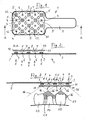
- Fig. 1 to 5 show a scanner 1, which comprises a planar support 2 and a handle part 3.
- ten projectors 4 and ten cameras 5 are provided side by side in a planar arrangement ("array").
- the projectors 4 and the cameras 5 are arranged alternately on the carrier 2.
- In the top row are from left to right, a camera 5, a projector 4, a camera 5, a projector 4 and a camera 5.
- In the second row are from left to right a projector 4, a camera 5, a projector 4, a camera 5 and a projector 4.
- the third and fourth rows are configured like the first and second rows. In both directions, the projectors 4 and the cameras 5 alternate in a ratio of 1: 1.
- each projector 4 comprises a light source 6, a mask 7 and a projector optics 8.
- the light source 6 is formed by an LED.
- the mask 7 is formed as a slide or LCD.
- the projector optics 8 consists of a lens.
- Each camera 5 comprises an image sensor 9 and a camera optics 10.
- the image sensor 5 is a CCD image sensor or CMOS image sensor.
- the camera optics 10 consists of a lens.
- Fig. 1 to 5 Are all projector optics 8 and all camera optics 10 combined to form a system optics 11.
- the system optics 11 is made in one piece. It has gaps 12 in the respective crossing points of two adjacent projectors 4 and cameras 5.
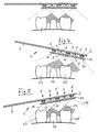
- Fig. 3 to 5 In addition to the scanner 1, three teeth 13, 14, 15 are shown.
- the tooth 14 is ground, the adjacent teeth 13, 15 are not ground and form the environment of the ground tooth 14.
- the conical fields of view 16 of the image sensors 9 drawn.
- the areas 17, which are detected by at least two image sensors 9, that is to say "seen", are hatched.
- the Fig. 3 to 5 show a possible chronological sequence when scanning the teeth 13, 14, 15. The fact that the scanner 1 is guided around the teeth 13, 14, 15, enough data can be obtained for the entire object representation.
- the carrier 2 'of the scanner 1' has angled regions, namely angled sides 18.
- the carrier 2 ' has a concave shape.
- the angled sides 18 serve to accommodate even more and better quality data on the tooth flanks.
- Fig. 9 shows a further modification of a scanner with a carrier 2 ", which has the shape of a denture arch.
- the projectors 4 and the cameras 5 are arranged in the form of a dental arch.
- the metrological method for determining the 3D coordinates of the objects or teeth can be based on a photogrammetric evaluation of several individual images, ie on the method of observing the object with multiple cameras and using suitable algorithms to find and correlate the same features in the individual images ,
- a specific area of the object or tooth can be detected.
- the individual recordings taken by the cameras can be combined to form a total recording. This process is referred to as "registering" or "matching".
- the scanner can be moved around the object to capture multiple or all areas of the object. In this way, an entire object presentation can be made from several whole shots.
- the pattern to be projected may be stochastic or ordered. It can consist of lines or cross lattices. It can be a temporally constant or temporally variable or sequential pattern.
- the pattern can be any graphic pattern (dots, lines, grid, etc.).
- the pattern may be a gray value pattern or a color pattern.
- the pattern can be projected with transmitted light, for example as a chrome mask (slide) or as an LED projection. However, the pattern can also be projected by reflection, for example as LCOS or DLP projection.
- the invention makes it possible to determine the 3D coordinates of an object. This can be done by calculating the 3D coordinates via the correlation of the same features in several, at least two, 2D images. According to this method, matching identical pixels can be found in two or more 2D images taken from different directions.
- the calibration of the cameras and triangulation or bundle triangulation can be used to calculate the 3D coordinates of the object points. In order to be able to clearly establish the assignment of the same features in the 2D images, patterns are projected.
- the projectors are not part of this process the calibration; they are independent of the photogrammetric camera system.
- the captured 2D image must contain all the information needed to calculate the 3D coordinates.
- a pattern is usually projected onto the object. To project this pattern different properties of the light can be exploited.
- the pattern may be a cross lattice of different colors, as shown in FIG DE 102 12 364 A1 is described. This procedure requires the projector to be calibrated with the camera. The method may be performed by calculating the 3D coordinates with the 2D image from a camera and the projected pattern, and that those 3D coordinates with the coordinates obtained from a 2D image from another camera and calculated from the projected pattern, correlated and optimized.
- the optionally used tracking system can be an optical or an interferometric tracking system.
- the optionally used tracking system can be an optical or an interferometric tracking system.
- the acceleration sensors can provide three translation information.
- the gyrometers can provide three rotation information, that is information about the orientation of the scanner. It is particularly advantageous to provide both acceleration sensors and gyrometers, thereby obtaining 6D information.
Landscapes
- Physics & Mathematics (AREA)
- General Physics & Mathematics (AREA)
- Health & Medical Sciences (AREA)
- Engineering & Computer Science (AREA)
- Epidemiology (AREA)
- General Health & Medical Sciences (AREA)
- Oral & Maxillofacial Surgery (AREA)
- Dentistry (AREA)
- Computer Vision & Pattern Recognition (AREA)
- Life Sciences & Earth Sciences (AREA)
- Animal Behavior & Ethology (AREA)
- Optics & Photonics (AREA)
- Public Health (AREA)
- Veterinary Medicine (AREA)
- Multimedia (AREA)
- Radar, Positioning & Navigation (AREA)
- Remote Sensing (AREA)
- Dental Tools And Instruments Or Auxiliary Dental Instruments (AREA)
- Length Measuring Devices By Optical Means (AREA)
Abstract
Description
- Die Erfindung betrifft einen Scanner zur Abtastung eines Objekts, insbesondere eines oder mehrerer Zähne oder eines Zahnmodells, und eine Vorrichtung zur Ermittlung der 3D-Koordinaten eines Objekts, insbesondere eines oder mehrerer Zähne oder eines Zahnmodells. Als Zähne im Sinne der Erfindung werden präparierte und nicht präparierte Zähne und auch Zahnersatz angesehen.
- Vorrichtungen und Verfahren zur Ermittlung der 3D-Koordinaten eines Objekts sind bereits bekannt. In der
EP 299 490 B2 - Aus der prioritätsälteren, nicht vorveröffentlichten deutschen Patentanmeldung
10 2007 060 263.6 ist eine Vorrichtung zur Ermittlung der 3D-Koordinaten eines Objekts, insbesondere eines oder mehrerer Zähne oder eines Zahnmodells, mit einem Scanner zur Abtastung des Objekts und einer Auswerteeinrichtung zur Ermittlung der 3D-Koordinaten des Objekts aus den von dem Scanner aufgenommenen Bildern bekannt. Der Scanner umfaßt einen Projektor zum Projizieren eines Musters auf das Objekt und eine Kamera, die eine Aufnahmeoptik mit einer ersten Bildoptik und einer zweiten Bildoptik sowie einen Bildsensor umfaßt. - Aufgabe der Erfindung ist es, einen verbesserten Scanner und eine verbesserte Vorrichtung der eingangs angegebenen Art vorzuschlagen.
- Erfindungsgemäß wird diese Aufgabe durch einen Scanner mit den Merkmalen des Anspruchs 1 gelöst. Der Scanner dient zur Abtastung eines Objekts, insbesondere eines oder mehrerer Zähne, wobei einer oder mehrere oder alle Zähne präpariert sein können. Der Begriff des Präparierens umfaßt einerseits die zahnmedizinische Präparation, also beispielsweise das Beschleifen eines Zahnstumpfs, und andererseits die Präparation, die zum Scannen eines Zahns mit optischer Meßtechnik vorteilhaft oder notwendig ist, beispielsweise das Einsprühen des zu scannenden Bereichs mit weißem Spray.
- Der Scanner umfaßt einen Träger, auf dem mehrere Projektoren zum Projizieren eines Musters auf das Objekt und mehrere Kameras zur Aufnahme des Objekts in einer Anordnung vorgesehen sind. Die Projektoren und Kameras können als "Array" angeordnet sein. Die erfindungsgemäße Anordnung der Projektoren und Träger ist insbesondere zur Anwendung bei beengten Platzverhältnissen und in schwer zugänglichen Bereichen geeignet, wie sie insbesondere in der Mundhöhle eines Patienten vorliegen, in der die Zähne gescannt werden sollen. Durch die Vielzahl der Kameras ist gewährleistet, daß eine ausreichende Anzahl verschiedener Bilder für die Auswertung erstellt werden kann. Durch die Vielzahl der Projektoren ist gewährleistet, daß eine ausreichende Anzahl von Mustern auf die zu scannenden Bereiche der Zähne projiziert werden kann.
- Der erfindungsgemäße Scanner kann insbesondere als miniaturisierter Scanner ausgebildet werden. Er ist zum Abtasten von Zähnen im Mund eines Patienten besonders geeignet. Er ist allerdings auch für andere Anwendungen besonders geeignet, bei denen die abzutastenden Objekte schwer zugänglich sind. Insbesondere kann der erfindungsgemäße Scanner für eine endoskopische Digitalisierung und/oder in schwer zugänglichen Kavitäten und/oder Kanälen von Maschinen und/oder Apparaten geeignet sein.
- Jeder Bildsensor erzeugt ein 2D-Bild. Aus den 2D-Bildern können die 3D-Koordinaten des Objekts bestimmt werden. Dies kann durch ein meßtechnisches Verfahren geschehen, das auf der Auswertung von mehreren 2D-Bildern, auf denen dieselben Objektpunkte abgebildet sind, basiert. Bei diesem Verfahren können mit geeigneten Algorithmen in verschiedenen 2D-Bildern dieselben Merkmale gefunden und korreliert werden. Bei einem kalibrierten System, wenn also die Lage und Orientierung der Kameras bekannt sind, kann zu jedem Objektpunkt, der sich in verschiedenen 2D-Bildern befindet, ein Abstandswert und damit eine 3D-Koordinate - im Koordinatensystem des Scanners - berechnet werden. Um in den verschiedenen 2D-Bildern dieselben Merkmale des Objekts zu finden, werden Muster auf das Objekt projiziert. Durch das oder die projizierten Muster können in verschiedenen 2D-Bildern die einander entsprechenden Objektpunkte gefunden werden. Auf diese Weise kann aus den 2D-Bildern eine 3D-Punktwolke bestimmt werden, die die Oberfläche des Objekts repräsentiert.
- Ferner ist es möglich, mehrere 3D-Punktwolken zu einer gesamten 3D-Punktwolke zusammenzufügen, die das gesamte Objekt repräsentiert. Hierfür können mehrere 3D-Punktwolken aus jeweils verschiedenen Richtungen bestimmt werden. Der Scanner kann um das Objekt bewegt werden, um mehrere oder alle Bereiche des Objektes zu erfassen.
- Vorteilhafte Weiterbildungen sind in den Unteransprüchen beschrieben.
- Vorteilhaft ist es, wenn die Projektoren und Kameras in einer flächenhaften Anordnung auf dem Träger vorgesehen sind.
- Die Projektoren und Kameras können auf dem Träger abwechselnd angeordnet sein. Dabei ist es möglich, neben einem Projektor eine Kamera anzuordnen und dies dann zu wiederholen, so daß die Projektoren und Kameras im Verhältnis 1:1 alternierend angeordnet sind. Dieses Muster kann in entsprechender Weise in die Fläche ausgedehnt werden. Es ist allerdings auch möglich, mehr Projektoren als Kameras oder mehr Kameras als Projektoren vorzusehen. Die Anordnung kann regelmäßig oder unregelmäßig sein.
- Die Projektoren können jeweils eine Lichtquelle, eine Maske und eine Projektoroptik umfassen. Bei der Lichtquelle handelt es sich vorzugsweise um eine LED. Die Projektoroptik kann aus einer oder mehreren Linsen bestehen. Die Maske kann von einer LCD gebildet werden.
- Vorteilhaft ist es, wenn die Maske und die Projektoroptik, insbesondere eine Linse der Projektoroptik, eine Verbundeinheit bilden. Besonders vorteilhaft ist es, wenn die Maske auf die Projektoroptik, insbesondere auf eine Linse der Projektoroptik, aufgedampft ist. Die Maske ist insbesondere als aufgedampfte Chrommaske hergestellt.
- Nach einer weiteren vorteilhaften Weiterbildung umfassen die Projektoren jeweils einen Musterprojektor und eine Projektoroptik. Bei dem Musterprojektor kann es sich um eine DLP oder LCOS handeln.
- Die Kameras können jeweils einen Bildsensor, insbesondere einen CCD-Sensor oder einen CMOS-Sensor, und eine Kameraoptik umfassen. Die Kameraoptik kann eine oder mehrere Linsen umfassen.
- Es ist möglich, daß jeder Projektor und/oder jede Kamera jeweils eine Projektoroptik bzw. Kameraoptik aufweist. In bestimmten Fällen kann es allerdings vorteilhaft sein, mehrere oder alle Projektoroptiken und/oder mehrere oder alle Kameraoptiken zu einer Systemoptik zusammenzufassen. Die Systemoptik kann einstückig sein. Sie kann als Verbund mehrerer oder aller Optiken bzw. Linsen hergestellt sein.
- Der Träger, auf dem die Projektoren und Kameras vorgesehen sind, kann eben ausgestaltet sein. In bestimmten Anwendungsfällen ist es allerdings vorteilhaft, wenn der Träger abgewinkelte Bereiche aufweist. Insbesondere kann der Träger abgewinkelte Seiten aufweisen. Der Träger ist vorzugsweise konkav ausgebildet.
- Nach einer weiteren vorteilhaften Weiterbildung weist der Träger die Form eines Gebißbogens auf.
- Die der Erfindung zugrundeliegende Aufgabe wird bei einer Vorrichtung zur Ermittlung der 3D-Koordinaten eines Objekts, insbesondere eines Zahns, durch die Merkmale des Anspruchs 10 gelöst. Die Vorrichtung umfaßt einen erfindungsgemäßen Scanner zur Abtastung des Objekts bzw. Zahns und eine Auswerteeinrichtung, insbesondere einen Computer, insbesondere einen PC einschließlich der zugehörigen Software, zur Ermittlung der 3D-Koordinaten des Objekts aus den von dem Scanner aufgenommenen Bildern.
- Für die Durchführung der Erfindung ist ein Tracking-System nicht erforderlich. In bestimmten Fällen kann es allerdings vorteilhaft sein, wenn die erfindungsgemäße Vorrichtung ein Tracking-System zum Ermitteln der Lage und Orientierung des Scanners umfaßt. Das Tracking-System kann dadurch gebildet werden, daß der Scanner einen oder mehrere Sensoren zur Erkennung von Lage und Orientierung des Scanners aufweist. Insbesondere kann das Tracking-System dadurch gebildet werden, daß der Scanner Beschleunigungssensoren und/oder Gyrometer aufweist. Es ist möglich, daß die Informationen des oder der Sensoren zur Erkennung von Lage und Orientierung des Scanners und/oder des oder der Beschleunigungssensoren und/oder des oder der Gyrometer, insbesondere deren 6D-Informationen, durch zeitliche Integration auf die Position und Drehstellung des Scanners zurückgerechnet werden. Stattdessen oder zusätzlich kann allerdings auch ein anderes Tracking-System verwendet werden, insbesondere ein Infrarot-Tracking-System.
- Ausführungsbeispiele der Erfindung werden nachstehend anhand der beigefügten Zeichnung im einzelnen erläutert. In der Zeichnung zeigt
- Fig. 1
- einen Scanner in einer Ansicht von oben,
- Fig. 2
- einen Schnitt längs der Linie A-A in
Fig. 1 , - Fig. 3
- den Scanner gemäß
Fig. 1 und 2 mit einer Gruppe von Zähnen, - Fig. 4
- den Scanner gemäß
Fig. 3 in einer nach rechts geneigten Lage, - Fig. 5
- den Scanner gemäß
Fig. 3 in einer nach links geneigten Lage, - Fig. 6
- eine Abwandlung des Scanners gemäß
Fig. 1 bis 5 , dessen Träger abgewinkelte Seiten aufweist, - Fig. 7
- den Scanner gemäß
Fig. 6 in zwei perspektivischen Darstellungen, - Fig. 8
- einen Schnitt durch den Scanner gemäß
Fig. 6 und 7 und - Fig. 9
- einen weiteren abgewandelten Scanner, dessen Träger die Form eines Gebißbogens aufweist.
-
Fig. 1 bis 5 zeigen einen Scanner 1, der einen ebenen Träger 2 und ein Griffteil 3 umfaßt. Auf dem Träger 2 sind zehn Projektoren 4 und zehn Kameras 5 nebeneinander in einer flächenhaften Anordnung ("Array") vorgesehen. Die Projektoren 4 und die Kameras 5 sind auf dem Träger 2 abwechselnd angeordnet. In der obersten Reihe befinden sich von links nach rechts eine Kamera 5, ein Projektor 4, eine Kamera 5, ein Projektor 4 und eine Kamera 5. In der zweiten Reihe befinden sich von links nach rechts ein Projektor 4, eine Kamera 5, ein Projektor 4, eine Kamera 5 und ein Projektor 4. Die dritte und vierte Reihe sind wie die erste und zweite Reihe ausgestaltet. In beiden Richtungen wechseln sich die Projektoren 4 und die Kameras 5 im Verhältnis 1:1 ab. - Aus
Fig. 2 ist ersichtlich, daß jeder Projektor 4 eine Lichtquelle 6, eine Maske 7 und eine Projektoroptik 8 umfaßt. Die Lichtquelle 6 wird von einer LED gebildet. Die Maske 7 ist als Dia oder LCD ausgebildet. Die Projektoroptik 8 besteht aus einer Linse. - Jede Kamera 5 umfaßt einen Bildsensor 9 und eine Kameraoptik 10. Der Bildsensor 5 ist ein CCD-Bildsensor oder CMOS-Bildsensor. Die Kameraoptik 10 besteht aus einer Linse.
- Bei der Ausführungsform nach
Fig. 1 bis 5 sind alle Projektoroptiken 8 und alle Kameraoptiken 10 zu einer Systemoptik 11 zusammengefaßt. Die Systemoptik 11 ist aus einem Stück hergestellt. Sie weist in den jeweiligen Kreuzungspunkten zweier benachbarter Projektoren 4 und Kameras 5 jeweils Lücken 12 auf. - In
Fig. 3 bis 5 sind zusätzlich zu dem Scanner 1 noch drei Zähne 13, 14, 15 dargestellt. Der Zahn 14 ist beschliffen, die Nachbarzähne 13, 15 sind nicht beschliffen und bilden die Umgebung des beschliffenen Zahnes 14. Ferner sind inFig. 3 bis 5 die kegelförmigen Sichtfelder 16 der Bildsensoren 9 eingezeichnet. Die Bereiche 17, die von jeweils mindestens zwei Bildsensoren 9 erfaßt, also "gesehen" werden, sind schraffiert dargestellt. - Die
Fig. 3 bis 5 zeigen eine mögliche zeitliche Abfolge beim Scannen der Zähne 13, 14, 15. Dadurch, daß der Scanner 1 um die Zähne 13, 14, 15 herumgeführt wird, können genügend Daten für die gesamte Objektrepräsentation erhalten werden. - Bei der in
Fig. 6 bis 8 gezeigten Abwandlung des Scanners werden bereits beschriebene Bestandteile, die mit denselben Bezugszeichen versehen sind, nicht erneut erläutert. Hier weist der Träger 2' des Scanners 1' abgewinkelte Bereiche, nämlich abgewinkelte Seiten 18 auf. Der Träger 2' hat eine konkave Form. Die abgewinkelten Seiten 18 dienen dazu, um noch mehr und qualitativ bessere Daten an den Zahnflanken aufnehmen zu können. -
Fig. 9 zeigt eine weitere Abwandlung eines Scanners mit einem Träger 2", der die Form eines Gebißbogens aufweist. Die Projektoren 4 und die Kameras 5 sind in der Form eines Gebißbogens angeordnet. - Das meßtechnische Verfahren zum Bestimmen der 3D-Koordinaten der Objekte bzw. Zähne kann auf einer photogrammetrischen Auswertung von mehreren Einzelaufnahmen basieren, also auf dem Verfahren, das Objekt mit mehreren Kameras zu beobachten und mit geeigneten Algorithmen dieselben Merkmale in den Einzelaufnahmen zu finden und zu korrelieren. Durch eine Einzelaufnahme kann ein bestimmter Bereich des Objekts bzw. Zahns erfaßt werden. Um das gesamte Objekt bzw. den gesamten Zahn oder mehrere oder alle Zähne und möglicherweise auch deren Umgebung zu erfassen, können die von den Kameras aufgenommenen Einzelaufnahmen zu einer Gesamtaufnahme zusammengefügt werden. Dieser Vorgang wird als "registrieren" bzw. "matchen" bezeichnet. Der Scanner kann um das Objekt bewegt werden, um mehrere oder alle Bereiche des Objektes zu erfassen. Auf diese Weise kann aus mehreren Gesamtaufnahmen eine gesamte ObjektRepräsentation hergestellt werden.
- Das zu projizierende Muster kann stochastisch oder geordnet sein. Es kann aus Linien oder Kreuzgittern bestehen. Es kann sich um ein zeitlich konstantes oder zeitlich veränderliches bzw. sequentielles Muster handeln. Das Muster kann ein beliebiges graphisches Muster sein (Punkte, Linien, Gitter etc.). Bei dem Muster kann es sich um ein Grauwertmuster oder um ein Farbmuster handeln. Das Muster kann mit Durchlicht projiziert werden, beispielsweise als Chrom-Maske (Dia) oder als LED-Projektion. Das Muster kann allerdings auch durch Reflektion projiziert werden, beispielsweise als LCOS- oder DLP-Projektion.
- Durch die Erfindung ist es möglich, die 3D-Koordinaten eines Objekts zu bestimmen. Dies kann dadurch geschehen, daß die 3D-Koordinaten über die Korrelation gleicher Merkmale in mehreren, mindestens zwei, 2D-Bildern berechnet werden. Nach diesem Verfahren lassen sich in zwei oder mehr 2D-Bildern, die aus unterschiedlichen Richtungen aufgenommen worden sind, zugehörige gleiche Bildpunkte finden. Über die Kalibration der Kameras und eine Triangulation bzw. Bündeltriangulation lassen sich damit die 3D-Koordinaten der Objektpunkte berechnen. Um die Zuordnung der gleichen Merkmale in den 2D-Bildern eindeutig herstellen zu können, werden Muster projiziert. Bei diesem Verfahren sind die Projektoren nicht Bestandteil der Kalibirierung; sie sind unabhängig von dem photogrammetrischen Kamerasystem.
- Es ist allerdings auch möglich, andere Verfahren zur Bestimmung der 3D-Koordinaten des Objekts durchzuführen. Insbesondere können Verfahren der "Einbild-Meßtechnik" angewandt werden, also Verfahren, mit denen man aus einem einzigen 2D-Bild die 3D-Koordinaten des Objekts berechnen kann. Um dieses Verfahren durchführen zu können und um mehrere sequentielle 2D-Bilder desselben Bereichs zu vermeiden, muß das aufgenommene 2D-Bild alle Informationen zur Berechnung der 3D-Koordinaten enthalten. Um dies zu gewährleisten wird üblicherweise ein Muster auf das Objekt projiziert. Um dieses Muster zu projizieren können unterschiedliche Eigenschaften des Lichts ausgenutzt werden. Beispielsweise kann es sich bei dem Muster um ein Kreuzgitter mit unterschiedlichen Farben handeln, wie dies in der
DE 102 12 364 A1 beschrieben ist. Bei diesem Verfahren muß der Projektor zusammen mit der Kamera kalibriert sein. Das Verfahren kann in der Weise durchgeführt werden, daß mit dem 2D-Bild aus einer Kamera und mit dem projizierten Muster die 3D-Koordinaten berechnet werden und daß diese 3D-Koordinaten mit den Koordinaten, die aus einem 2D-Bild aus einer anderen Kamera und aus dem projizierten Muster berechnet wurden, korreliert und optimiert werden. - Bei dem wahlweise zu verwendenden Trackingsystem kann es sich um ein optisches oder ein interferometrisches Trackingsystem handeln. Es ist allerdings auch möglich, das Trackingsystem durch an dem Scanner befestigte Sensoren zur Erkennung von Lage und Orientierung des Scanners und/oder Beschleunigungssensoren und/oder Gyrometer zu realisieren, mit deren Hilfe über die zeitliche Integration auf Geschwindigkeit und Position des Scanners zurückgerechnet werden kann. Die Beschleunigungssensoren können drei Translationsinformationen liefern. Die Gyrometer können drei Rotationsinformationen liefern, also Informationen über die Orientierung des Scanners. Besonders vorteilhaft ist es, sowohl Beschleunigungssensoren als auch Gyrometer vorzusehen, um dadurch 6D-Informationen zu erhalten.
Claims (12)
- Scanner zum Abtasten eines Objekts, insbesondere eines oder mehrere Zähne (13, 14, 15) oder eines Zahnmodells, mit einem Träger (2), auf dem mehrere Projektoren (4) zum Projizieren eines Musters auf das Objekt und mehrere Kameras (5) zur Aufnahme des Objekts in einer Anordnung vorgesehen sind.
- Scanner nach Anspruch 1, dadurch gekennzeichnet, daß die Projektoren (4) und Kameras (5) in einer flächenhaften Anordnung auf dem Träger (2) vorgesehen sind.
- Scanner nach Anspruch 1 oder 2, dadurch gekennzeichnet, daß die Projektoren (4) und die Kameras (5) auf dem Träger (2) abwechselnd angeordnet sind.
- Scanner nach einem der vorhergehenden Ansprüche, dadurch gekennzeichnet, daß die Projektoren (4) jeweils eine Lichtquelle (6), eine Maske (7) und eine Projektoroptik (8) umfassen.
- Scanner nach Anspruch 4, dadurch gekennzeichnet, daß die Maske (7) und die Projektoroptik (8) eine Verbundeinheit bilden.
- Scanner nach einem der Ansprüche 1 bis 3, dadurch gekennzeichnet, daß die Projektoren jeweils einen Musterprojektor und eine Projektoroptik umfassen.
- Scanner nach einem der vorhergehenden Ansprüche, dadurch gekennzeichnet, daß die Kameras jeweils einen Bildsensor (9) und eine Kameraoptik (10) umfassen.
- Scanner nach einem der vorhergehenden Ansprüche, dadurch gekennzeichnet, daß mehrere oder alle Projektoroptiken (8) und/oder mehrere oder alle Kameraoptiken (10) zu einer Systemoptik (11) zusammengefaßt sind.
- Scanner nach einem der vorhergehenden Ansprüche, dadurch gekennzeichnet, daß der Träger (2') abgewinkelte Bereiche (18) aufweist.
- Scanner nach einem der vorhergehenden Ansprüche, dadurch gekennzeichnet, daß der Träger (2, 2') die Form eines Gebißbogens aufweist.
- Vorrichtung zur Ermittlung der 3D-Koordinaten eines Objekts, insbesondere eines oder mehrerer Zähne (13, 14, 15) oder eines Zahnmodells, mit einem Scanner (1) zur Abtastung des Objekts und einer Auswerteeinrichtung zur Ermittlung der 3D-Koordinaten des Objekts aus den von dem Scanner aufgenommenen Bildern,
gekennzeichnet durch
einen Scanner nach einem der Ansprüche 1 bis 10. - Vorrichtung nach Anspruch 11, gekennzeichnet durch ein Tracking-System zum Ermitteln der Lage und Orientierung des Scanners (1).
Applications Claiming Priority (1)
| Application Number | Priority Date | Filing Date | Title |
|---|---|---|---|
| DE102008047816A DE102008047816B4 (de) | 2008-09-18 | 2008-09-18 | Vorrichtung zur Ermittlung der 3D-Koordinaten eines Objekts, insbesondere eines Zahns |
Publications (2)
| Publication Number | Publication Date |
|---|---|
| EP2166303A1 true EP2166303A1 (de) | 2010-03-24 |
| EP2166303B1 EP2166303B1 (de) | 2014-10-01 |
Family
ID=41170015
Family Applications (1)
| Application Number | Title | Priority Date | Filing Date |
|---|---|---|---|
| EP09010072.8A Active EP2166303B1 (de) | 2008-09-18 | 2009-08-04 | Vorrichtung zur Ermittlung der 3D-Koordinaten eines Objekts insbesondere eines Zahns |
Country Status (4)
| Country | Link |
|---|---|
| US (1) | US9671220B2 (de) |
| EP (1) | EP2166303B1 (de) |
| JP (1) | JP5647778B2 (de) |
| DE (1) | DE102008047816B4 (de) |
Cited By (18)
| Publication number | Priority date | Publication date | Assignee | Title |
|---|---|---|---|---|
| FR2960962A1 (fr) * | 2010-06-08 | 2011-12-09 | Francois Duret | Dispositif de mesures tridimensionnelles et temporelles par empreinte optique en couleur. |
| EP2400261A1 (de) * | 2010-06-21 | 2011-12-28 | Leica Geosystems AG | Optisches Messverfahren und Messsystem zum Bestimmen von 3D-Koordinaten auf einer Messobjekt-Oberfläche |
| WO2012126022A1 (de) * | 2011-03-18 | 2012-09-27 | A.Tron3D Gmbh | Vorrichtung zum aufnehmen von bildern von dreidimensionalen objekten |
| WO2013008097A1 (en) | 2011-07-08 | 2013-01-17 | Duret Francois | Three-dimensional measuring device used in the dental field |
| WO2013116881A1 (de) * | 2012-02-06 | 2013-08-15 | A.Tron3D Gmbh | Vorrichtung zum erfassen der dreidimensionalen geometrie von objekten und verfahren zum betreiben derselben |
| US9453722B2 (en) | 2009-08-26 | 2016-09-27 | Degudent Gmbh | Method and arrangement for determining a combined data record for a masticatory organ to be measured |
| WO2016172411A1 (en) * | 2015-04-24 | 2016-10-27 | Faro Technologies, Inc. | Two-camera triangulation scanner with detachable coupling mechanism |
| US9599455B2 (en) | 2012-12-14 | 2017-03-21 | Faro Technologies, Inc. | Device for optically scanning and measuring an environment |
| EP3098563A3 (de) * | 2015-05-29 | 2017-05-03 | Nikolaus Kreuzhermes | System und verfahren zur erfassung von bilddaten einer oberfläche eines objekts |
| EP3403568A1 (de) * | 2010-03-30 | 2018-11-21 | 3Shape A/S | Scannen von eingeschränkt zugänglichen hohlräumen |
| US10159547B2 (en) | 2014-06-11 | 2018-12-25 | Quarz Partners Ag | Measuring apparatus and method for three-dimensional measurement of an oral cavity |
| CN110623763A (zh) * | 2018-06-22 | 2019-12-31 | 阿莱恩技术有限公司 | 用多个微型摄像头和微型图案投射器的口内3d扫描仪 |
| WO2020264035A1 (en) * | 2019-06-24 | 2020-12-30 | Align Technology, Inc. | Intraoral 3d scanner employing multiple miniature cameras and multiple miniature pattern projectors |
| EP3490439B1 (de) | 2016-07-27 | 2023-06-07 | Align Technology, Inc. | Intraoraler scanner mit zahnmedizinischen diagnosefähigkeiten |
| EP3810027B1 (de) | 2018-06-22 | 2023-08-02 | Align Technology, Inc. | Intraoraler 3d-scanner mit mehreren miniaturkameras und mehreren miniaturmusterprojektoren |
| EP4332897A1 (de) | 2022-09-02 | 2024-03-06 | Brütsch Elektronik AG | Vorrichtung und verfahren zur durchführung eines intraoralen scans |
| US12263063B2 (en) | 2016-07-27 | 2025-04-01 | Align Technology, Inc. | Intraoral scanning apparatus |
| US12268574B2 (en) | 2018-01-26 | 2025-04-08 | Align Technology, Inc. | Diagnostic intraoral methods and apparatuses |
Families Citing this family (34)
| Publication number | Priority date | Publication date | Assignee | Title |
|---|---|---|---|---|
| DE102007060263A1 (de) * | 2007-08-16 | 2009-02-26 | Steinbichler Optotechnik Gmbh | Vorrichtung zur Ermittlung der 3D-Koordinaten eines Objekts, insbesondere eines Zahns |
| WO2010145669A1 (en) | 2009-06-17 | 2010-12-23 | 3Shape A/S | Focus scanning apparatus |
| DE102010049310A1 (de) | 2010-10-22 | 2012-04-26 | Weber Maschinenbau Gmbh Breidenbach | Abtastvorrichtung und Verfahren zum Ermitteln der Kontur eines Objekts |
| KR101175616B1 (ko) | 2010-11-11 | 2012-08-21 | 데오덴탈 주식회사 | 구강용 스캐너 |
| ES2699529T3 (es) | 2011-07-15 | 2019-02-11 | 3Shape As | Detección de un objeto móvil al escanear en 3D un objeto rígido |
| WO2013121605A1 (ja) * | 2012-02-15 | 2013-08-22 | メディア株式会社 | 口腔内歯列撮影装置 |
| US20150118638A1 (en) * | 2012-04-05 | 2015-04-30 | Trispera Dental, Inc. | Intraoral Imaging Apparatus |
| DE102012206472B4 (de) * | 2012-04-19 | 2015-07-09 | Fraunhofer-Gesellschaft zur Förderung der angewandten Forschung e.V. | Projektionssystem mit statischen mustererzeugungselementen und mehreren optischen kanälen zur optischen 3d-vermessung |
| US10869020B2 (en) * | 2012-06-29 | 2020-12-15 | Inb Vision Ag | Method for capturing images of a preferably structured surface of an object and device for image capture |
| WO2014102779A2 (en) | 2012-12-24 | 2014-07-03 | Dentlytec G.P.L. Ltd | Device and method for subgingival measurement |
| DE102013211200B4 (de) * | 2013-06-14 | 2018-11-29 | Kulzer Gmbh | Scanbarer Löffel zur Herstellung einer Dentalprothese |
| KR101499649B1 (ko) * | 2013-08-20 | 2015-03-06 | 조현재 | 구강촬영용 트레이, 구강촬영용 트레이를 포함하는 구강촬영장치 및 구강촬영 시스템 |
| WO2015118120A1 (en) | 2014-02-07 | 2015-08-13 | 3Shape A/S | Detecting tooth shade |
| DE102014205784B4 (de) * | 2014-03-27 | 2024-01-18 | Sirona Dental Systems Gmbh | Scanvorrichtung |
| SE1400260A1 (sv) | 2014-05-22 | 2015-11-23 | Arrangeman och metod för tillverkning av individuellt utformade objekt såsom dentala restaurationer | |
| PL3145436T3 (pl) * | 2014-05-23 | 2021-07-19 | Apollo Oral Scanner, LLC | Nowe urządzenie skanera stomatologicznego oraz system i sposoby użytkowania |
| US12259231B2 (en) | 2015-01-18 | 2025-03-25 | Dentlytec G.P.L. Ltd. | Intraoral scanner |
| US9844426B2 (en) | 2015-03-12 | 2017-12-19 | Align Technology, Inc. | Digital dental tray |
| US10159542B2 (en) | 2015-05-01 | 2018-12-25 | Dentlytec G.P.L. Ltd. | System, device and methods for dental digital impressions |
| EP3405092A2 (de) | 2016-01-18 | 2018-11-28 | Dentlytec G.P.L. Ltd. | Intraoraler scanner |
| EP3410919B1 (de) | 2016-02-01 | 2023-12-06 | Martin, Marco | Zahnärztliche abbildungsvorrichtung und verfahren zur aufzeichnung fotografischer abdrücke |
| EP3471627B1 (de) | 2016-06-16 | 2025-12-31 | Ark Surgical Ltd. | Gewebeeindämmungsvorrichtung zur verwendung bei chirurgischen eingriffen |
| US12285188B2 (en) | 2016-09-10 | 2025-04-29 | Ark Surgical Ltd. | Laparoscopic workspace device |
| WO2018047180A1 (en) | 2016-09-10 | 2018-03-15 | Ark Surgical Ltd. | Laparoscopic workspace device |
| DE102017204503A1 (de) * | 2017-03-17 | 2018-09-20 | Schott Ag | Beleuchtungssystem mit flachem Leuchtabschnitt |
| WO2019008586A1 (en) | 2017-07-04 | 2019-01-10 | Dentlytec G.P.L. Ltd | DENTAL DEVICE WITH PROBE |
| EP3658069B1 (de) * | 2017-07-26 | 2024-06-26 | Dentlytec G.P.L. Ltd. | Intraoraler scanner |
| US12491058B2 (en) | 2019-01-09 | 2025-12-09 | Dentlytec G.P.L. Ltd. | Dental device with probe and methods associated therewith |
| US10849723B1 (en) * | 2019-05-07 | 2020-12-01 | Sdc U.S. Smilepay Spv | Scanning device |
| IT201900006650A1 (it) * | 2019-05-08 | 2020-11-08 | Playcast S R L | Un sistema di scansione |
| DE102020133627A1 (de) | 2020-12-15 | 2022-06-15 | Infinisense Technologies GmbH | Verfahren und Intraoralscanner zum Erfassen der Topographie der Oberfläche eines transluzenten, insbesondere dentalen, Objektes |
| EP4262573B1 (de) | 2020-12-17 | 2026-04-22 | Ark Surgical Ltd. | Laparoskopische gewebeeindämmungsvorrichtung |
| CN121127723A (zh) * | 2023-03-17 | 2025-12-12 | 阿莱恩技术有限公司 | 口内扫描仪投射器对准和固定 |
| US12594148B2 (en) * | 2024-08-20 | 2026-04-07 | Cerna Diamant | Aid apparatus for positioning an orthodontic bracket in a center of a tooth |
Citations (9)
| Publication number | Priority date | Publication date | Assignee | Title |
|---|---|---|---|---|
| JPS61162706A (ja) | 1985-01-14 | 1986-07-23 | Hitachi Zosen Corp | 立体計測方法 |
| DE3810455A1 (de) | 1988-03-26 | 1989-10-05 | Michael Dr Radu | Verfahren und vorrichtung zur beruehrungsfreien raeumlichen erfassung eines unregelmaessigen koerpers |
| US5257184A (en) | 1990-04-10 | 1993-10-26 | Mushabac David R | Method and apparatus with multiple data input stylii for collecting curvilinear contour data |
| US5712803A (en) | 1995-06-23 | 1998-01-27 | Kreon Industrie | Method of acquiring and digitizing objects through a transparent wall |
| US20020171847A1 (en) | 2001-04-27 | 2002-11-21 | Tadashi Fukumoto | Three-dimensional shape-measuring system |
| US20040252312A1 (en) | 2003-06-12 | 2004-12-16 | Liang-Chia Chen | Apparatus and method for rapid and precise scanning of three-dimensional occlusal profile of dental cast |
| DE102004052199A1 (de) | 2004-10-20 | 2006-04-27 | Universität Stuttgart | Streifenprojektions-Triangulationsanordnung zur dreidimensionalen Objekterfassung, insbesondere auch zur dreidimensionalen Erfassung des Gesichts eines Menschen |
| DE102006013584A1 (de) | 2006-03-22 | 2007-09-27 | Benteler Automobiltechnik Gmbh | Vorrichtung und Verfahren zum Vermessen von Bauteilen |
| US20080101688A1 (en) | 2006-10-25 | 2008-05-01 | D4D Technologies, Llc | 3D photogrammetry using projected patterns |
Family Cites Families (24)
| Publication number | Priority date | Publication date | Assignee | Title |
|---|---|---|---|---|
| DE3723555C2 (de) | 1987-07-16 | 1994-08-11 | Steinbichler Hans | Verfahren zur Herstellung von Zahnersatz |
| US5372502A (en) * | 1988-09-02 | 1994-12-13 | Kaltenbach & Voight Gmbh & Co. | Optical probe and method for the three-dimensional surveying of teeth |
| US5347454A (en) * | 1990-04-10 | 1994-09-13 | Mushabac David R | Method, system and mold assembly for use in preparing a dental restoration |
| DE4134117C2 (de) * | 1991-10-15 | 1996-02-01 | Kaltenbach & Voigt | Verfahren zur optischen Vermessung von Objekten |
| DE4206836C2 (de) * | 1992-03-04 | 1994-07-14 | Kaltenbach & Voigt | Sonde zur optischen Vermessung von Zähnen |
| NZ293713A (en) * | 1994-09-28 | 1997-09-22 | William Richard Fright | Laser surface scanning system: shape of surface recorded by determining relative positions of laser, camera, and laser spot on surface with respect to fixed reference point |
| DE19634797A1 (de) * | 1996-08-29 | 1998-03-12 | Opel Helmut Dr | Bildwiedergabe-/Speichereinrichtung für ärztliche Diagnosezwecke |
| US7068825B2 (en) * | 1999-03-08 | 2006-06-27 | Orametrix, Inc. | Scanning system and calibration method for capturing precise three-dimensional information of objects |
| US7625335B2 (en) * | 2000-08-25 | 2009-12-01 | 3Shape Aps | Method and apparatus for three-dimensional optical scanning of interior surfaces |
| EP1467549B1 (de) * | 2000-10-20 | 2011-03-23 | FUJIFILM Corporation | Bildverarbeitungsvorrichtung, welche Informationen mit einem identifizierten Subjekt des Bildes verknüpft |
| JP2002328012A (ja) * | 2001-04-27 | 2002-11-15 | Minolta Co Ltd | 三次元形状測定システム |
| US20050202363A1 (en) * | 2002-02-21 | 2005-09-15 | Osterwalder J. M. | Dental imaging and treatment system |
| DE10212364A1 (de) | 2002-03-20 | 2003-10-16 | Steinbichler Optotechnik Gmbh | Verfahren und Vorrichtung zur Bestimmung der Absolut-Koordinaten eines Objekts |
| WO2004110309A2 (en) * | 2003-06-11 | 2004-12-23 | Case Western Reserve University | Computer-aided-design of skeletal implants |
| US20050142517A1 (en) * | 2003-12-30 | 2005-06-30 | Howard Frysh | System for producing a dental implant and method |
| US7961912B2 (en) * | 2004-10-14 | 2011-06-14 | Stevick Glen R | Method and apparatus for dynamic space-time imaging system |
| DE102004054876B3 (de) * | 2004-11-12 | 2006-07-27 | Sirona Dental Systems Gmbh | Vermessungseinrichtung zur 3D-Vermessung von Zahnmodellen, Verschiebeplatte und Verfahren dazu |
| US7609875B2 (en) * | 2005-05-27 | 2009-10-27 | Orametrix, Inc. | Scanner system and method for mapping surface of three-dimensional object |
| US7372642B2 (en) * | 2006-02-13 | 2008-05-13 | 3M Innovative Properties Company | Three-channel camera systems with non-collinear apertures |
| US9348463B2 (en) * | 2006-08-03 | 2016-05-24 | New York University | Retroreflection based multitouch sensor, method and program |
| US8090194B2 (en) * | 2006-11-21 | 2012-01-03 | Mantis Vision Ltd. | 3D geometric modeling and motion capture using both single and dual imaging |
| DE102007060263A1 (de) | 2007-08-16 | 2009-02-26 | Steinbichler Optotechnik Gmbh | Vorrichtung zur Ermittlung der 3D-Koordinaten eines Objekts, insbesondere eines Zahns |
| JP2009204991A (ja) * | 2008-02-28 | 2009-09-10 | Funai Electric Co Ltd | 複眼撮像装置 |
| US8129703B2 (en) * | 2008-03-12 | 2012-03-06 | Optimet, Optical Metrology Ltd. | Intraoral imaging system and method based on conoscopic holography |
-
2008
- 2008-09-18 DE DE102008047816A patent/DE102008047816B4/de active Active
-
2009
- 2009-08-04 EP EP09010072.8A patent/EP2166303B1/de active Active
- 2009-09-15 JP JP2009213252A patent/JP5647778B2/ja active Active
- 2009-09-16 US US12/560,704 patent/US9671220B2/en active Active
Patent Citations (9)
| Publication number | Priority date | Publication date | Assignee | Title |
|---|---|---|---|---|
| JPS61162706A (ja) | 1985-01-14 | 1986-07-23 | Hitachi Zosen Corp | 立体計測方法 |
| DE3810455A1 (de) | 1988-03-26 | 1989-10-05 | Michael Dr Radu | Verfahren und vorrichtung zur beruehrungsfreien raeumlichen erfassung eines unregelmaessigen koerpers |
| US5257184A (en) | 1990-04-10 | 1993-10-26 | Mushabac David R | Method and apparatus with multiple data input stylii for collecting curvilinear contour data |
| US5712803A (en) | 1995-06-23 | 1998-01-27 | Kreon Industrie | Method of acquiring and digitizing objects through a transparent wall |
| US20020171847A1 (en) | 2001-04-27 | 2002-11-21 | Tadashi Fukumoto | Three-dimensional shape-measuring system |
| US20040252312A1 (en) | 2003-06-12 | 2004-12-16 | Liang-Chia Chen | Apparatus and method for rapid and precise scanning of three-dimensional occlusal profile of dental cast |
| DE102004052199A1 (de) | 2004-10-20 | 2006-04-27 | Universität Stuttgart | Streifenprojektions-Triangulationsanordnung zur dreidimensionalen Objekterfassung, insbesondere auch zur dreidimensionalen Erfassung des Gesichts eines Menschen |
| DE102006013584A1 (de) | 2006-03-22 | 2007-09-27 | Benteler Automobiltechnik Gmbh | Vorrichtung und Verfahren zum Vermessen von Bauteilen |
| US20080101688A1 (en) | 2006-10-25 | 2008-05-01 | D4D Technologies, Llc | 3D photogrammetry using projected patterns |
Cited By (45)
| Publication number | Priority date | Publication date | Assignee | Title |
|---|---|---|---|---|
| EP2470857B1 (de) * | 2009-08-26 | 2018-05-02 | DENTSPLY SIRONA Inc. | Verfahren und anordnung zur ermittlung eines gesamtdatensatzes eines zu messenden kauorgans |
| US9453722B2 (en) | 2009-08-26 | 2016-09-27 | Degudent Gmbh | Method and arrangement for determining a combined data record for a masticatory organ to be measured |
| EP3403568A1 (de) * | 2010-03-30 | 2018-11-21 | 3Shape A/S | Scannen von eingeschränkt zugänglichen hohlräumen |
| CN103153167A (zh) * | 2010-06-08 | 2013-06-12 | 弗朗索瓦·迪莱特 | 三维暂存光学彩色图像摄取装置 |
| WO2011154656A1 (fr) * | 2010-06-08 | 2011-12-15 | Duret Francois | Dispositif de mesures tridimensionnelles et temporelles par empreinte optique en couleur |
| CN103153167B (zh) * | 2010-06-08 | 2016-10-26 | 弗朗索瓦·迪莱特 | 三维暂存光学彩色图像摄取装置 |
| FR2960962A1 (fr) * | 2010-06-08 | 2011-12-09 | Francois Duret | Dispositif de mesures tridimensionnelles et temporelles par empreinte optique en couleur. |
| US8520925B2 (en) | 2010-06-08 | 2013-08-27 | François Duret | Device for taking three-dimensional and temporal optical imprints in color |
| AU2011269189B2 (en) * | 2010-06-21 | 2013-09-26 | Leica Geosystems Ag | Optical measurement method and measurement system for determining 3D coordinates on a measurement object surface |
| EP2400261A1 (de) * | 2010-06-21 | 2011-12-28 | Leica Geosystems AG | Optisches Messverfahren und Messsystem zum Bestimmen von 3D-Koordinaten auf einer Messobjekt-Oberfläche |
| US20130100282A1 (en) * | 2010-06-21 | 2013-04-25 | Leica Geosystems Ag | Optical measurement method and measurement system for determining 3d coordinates on a measurement object surface |
| CN102947670A (zh) * | 2010-06-21 | 2013-02-27 | 莱卡地球系统公开股份有限公司 | 用于确定测量对象表面上的3d坐标的光学测量方法和测量系统 |
| KR101458991B1 (ko) | 2010-06-21 | 2014-11-12 | 라이카 게오시스템스 아게 | 측정 대상 표면에 대한 3d 좌표들을 결정하기 위한 광학 측정 방법 및 측정 시스템 |
| CN102947670B (zh) * | 2010-06-21 | 2015-11-25 | 莱卡地球系统公开股份有限公司 | 用于确定测量对象表面上的3d坐标的光学测量方法和测量系统 |
| WO2011160962A1 (de) * | 2010-06-21 | 2011-12-29 | Leica Geosystems Ag | Optisches messverfahren und messsystem zum bestimmen von 3d-koordinaten auf einer messobjekt-oberfläche |
| US9683837B2 (en) | 2010-06-21 | 2017-06-20 | Leica Geosystems Ag | Optical measurement method and measurement system for determining 3D coordinates on a measurement object surface |
| WO2012126022A1 (de) * | 2011-03-18 | 2012-09-27 | A.Tron3D Gmbh | Vorrichtung zum aufnehmen von bildern von dreidimensionalen objekten |
| WO2013008097A1 (en) | 2011-07-08 | 2013-01-17 | Duret Francois | Three-dimensional measuring device used in the dental field |
| WO2013116881A1 (de) * | 2012-02-06 | 2013-08-15 | A.Tron3D Gmbh | Vorrichtung zum erfassen der dreidimensionalen geometrie von objekten und verfahren zum betreiben derselben |
| US9861456B2 (en) | 2012-02-06 | 2018-01-09 | A.Tron3D Gmbh | Device for detecting the three-dimensional geometry of objects and method for the operation thereof |
| US10166090B2 (en) | 2012-02-06 | 2019-01-01 | A.Tron3D Gmbh | Device for detecting the three-dimensional geometry of objects and method for the operation thereof |
| US9599455B2 (en) | 2012-12-14 | 2017-03-21 | Faro Technologies, Inc. | Device for optically scanning and measuring an environment |
| US9858682B2 (en) | 2012-12-14 | 2018-01-02 | Faro Technologies, Inc. | Device for optically scanning and measuring an environment |
| US10159547B2 (en) | 2014-06-11 | 2018-12-25 | Quarz Partners Ag | Measuring apparatus and method for three-dimensional measurement of an oral cavity |
| WO2016172411A1 (en) * | 2015-04-24 | 2016-10-27 | Faro Technologies, Inc. | Two-camera triangulation scanner with detachable coupling mechanism |
| US9964402B2 (en) | 2015-04-24 | 2018-05-08 | Faro Technologies, Inc. | Two-camera triangulation scanner with detachable coupling mechanism |
| US10866089B2 (en) | 2015-04-24 | 2020-12-15 | Faro Technologies, Inc. | Two-camera triangulation scanner with detachable coupling mechanism |
| US10444009B2 (en) | 2015-04-24 | 2019-10-15 | Faro Technologies, Inc. | Two-camera triangulation scanner with detachable coupling mechanism |
| US11262194B2 (en) | 2015-04-24 | 2022-03-01 | Faro Technologies, Inc. | Triangulation scanner with blue-light projector |
| EP3098563A3 (de) * | 2015-05-29 | 2017-05-03 | Nikolaus Kreuzhermes | System und verfahren zur erfassung von bilddaten einer oberfläche eines objekts |
| EP3490439B1 (de) | 2016-07-27 | 2023-06-07 | Align Technology, Inc. | Intraoraler scanner mit zahnmedizinischen diagnosefähigkeiten |
| US12263063B2 (en) | 2016-07-27 | 2025-04-01 | Align Technology, Inc. | Intraoral scanning apparatus |
| US12268574B2 (en) | 2018-01-26 | 2025-04-08 | Align Technology, Inc. | Diagnostic intraoral methods and apparatuses |
| US12178685B2 (en) | 2018-06-22 | 2024-12-31 | Align Technology, Inc. | Dental scanning system with structured light projection |
| CN110623763A (zh) * | 2018-06-22 | 2019-12-31 | 阿莱恩技术有限公司 | 用多个微型摄像头和微型图案投射器的口内3d扫描仪 |
| AU2025201042B2 (en) * | 2018-06-22 | 2025-11-06 | Align Technology, Inc. | Intraoral 3d scanner employing multiple miniature cameras and multiple miniature pattern projectors |
| CN110623763B (zh) * | 2018-06-22 | 2023-03-14 | 阿莱恩技术有限公司 | 用多个微型摄像头和微型图案投射器的口内3d扫描仪 |
| EP3810027B1 (de) | 2018-06-22 | 2023-08-02 | Align Technology, Inc. | Intraoraler 3d-scanner mit mehreren miniaturkameras und mehreren miniaturmusterprojektoren |
| US12279929B2 (en) | 2018-06-22 | 2025-04-22 | Align Technology, Inc. | Intraoral 3D scanning system using structured light projection |
| US12143558B2 (en) | 2019-06-24 | 2024-11-12 | Align Technology, Inc. | Automatic calibration of intraoral 3D scanner |
| WO2020264035A1 (en) * | 2019-06-24 | 2020-12-30 | Align Technology, Inc. | Intraoral 3d scanner employing multiple miniature cameras and multiple miniature pattern projectors |
| EP4302684A3 (de) * | 2019-06-24 | 2024-03-20 | Align Technology, Inc. | Verfahren und system zur erzeugung eines digitalen dreidimensionalen bildes einer intraoralen dreidimensionalen oberfläche |
| US11563929B2 (en) | 2019-06-24 | 2023-01-24 | Align Technology, Inc. | Intraoral 3D scanner employing multiple miniature cameras and multiple miniature pattern projectors |
| WO2024047253A1 (de) | 2022-09-02 | 2024-03-07 | Brütsch Elektronik Ag | Vorrichtung und verfahren zur durchführung eines intraoralen scans |
| EP4332897A1 (de) | 2022-09-02 | 2024-03-06 | Brütsch Elektronik AG | Vorrichtung und verfahren zur durchführung eines intraoralen scans |
Also Published As
| Publication number | Publication date |
|---|---|
| US20100239136A1 (en) | 2010-09-23 |
| EP2166303B1 (de) | 2014-10-01 |
| JP5647778B2 (ja) | 2015-01-07 |
| DE102008047816A1 (de) | 2010-04-08 |
| DE102008047816B4 (de) | 2011-08-25 |
| US9671220B2 (en) | 2017-06-06 |
| JP2010069301A (ja) | 2010-04-02 |
Similar Documents
| Publication | Publication Date | Title |
|---|---|---|
| EP2166303B1 (de) | Vorrichtung zur Ermittlung der 3D-Koordinaten eines Objekts insbesondere eines Zahns | |
| DE102007060263A1 (de) | Vorrichtung zur Ermittlung der 3D-Koordinaten eines Objekts, insbesondere eines Zahns | |
| EP2212646B1 (de) | Verfahren zur optischen vermessung von objekten unter verwendung eines triangulationsverfahrens | |
| EP2079981B1 (de) | Vorrichtung und verfahren zum berührungslosen erfassen einer dreidimensionalen kontur | |
| DE102007054906B4 (de) | Verfahren zur optischen Vermessung der dreidimensionalen Geometrie von Objekten | |
| EP2273229B1 (de) | Verfahren zur Bestimmung der 3D-Koordinaten eines Objekts | |
| DE3829925C2 (de) | Vorrichtung zur optischen Vermessung von Zähnen in der Mundhöhle | |
| EP2574876B1 (de) | Verfahren und Vorrichtung zum Bestimmen der 3D-Koordinaten eines Objekts | |
| EP3298345B1 (de) | Kamera und verfahren zur dreidimensionalen vermessung und farbvermessung eines dentalen objekts | |
| EP2026034B1 (de) | Vorrichtung zur Ermittlung der 3D-Koordinaten eines Objekts, insbesondere eines Zahns | |
| DE10137241A1 (de) | Registrierung von Tiefenbildern mittels optisch projizierter Marken | |
| DE19638727A1 (de) | Verfahren zur Erhöhung der Signifikanz der dreidimensionalen Vermessung von Objekten | |
| DE19502459A1 (de) | Verfahren zur dreidimensionalen optischen Vermessung der Oberfläche von Objekten | |
| WO2003091660A1 (de) | Verfahren und vorrichtung zur bestimmung der räumlichen koordinaten eines gegenstandes | |
| WO2016041695A1 (de) | Verfahren und vorrichtung zum identifizieren von strukturelementen eines projizierten strukturmusters in kamerabildern | |
| EP0449859B1 (de) | Verfahren und vorrichtung zur beobachtung von moiremustern von zu untersuchenden oberflächen unter anwendung des moireverfahrens mit phasenshiften | |
| DE102013203312A1 (de) | Extraoraler Dentalscanner | |
| DE102012207499B3 (de) | Verfahren zur Vermessung einer Zahnsituation | |
| EP2470857B1 (de) | Verfahren und anordnung zur ermittlung eines gesamtdatensatzes eines zu messenden kauorgans | |
| DE3810455A1 (de) | Verfahren und vorrichtung zur beruehrungsfreien raeumlichen erfassung eines unregelmaessigen koerpers | |
| DE102012102580A1 (de) | Verfahren zum Messen eines Objektes sowie Intraoral-Scanner | |
| DE102004058655A1 (de) | Verfahren und Anordnung zum Messen von Geometrien eines Objektes mittels eines Koordinatenmessgerätes | |
| DE4314602A1 (de) | Verfahren und Vorrichtung zur Herstellung von Paßkörpern | |
| DE102011123029B3 (de) | Verfahren zur optischen dreidimensionalen Vermessung eines dentalen Objekts | |
| DE19834597A1 (de) | Vorrichtung und Verfahren zur Farbaufnahme eines Bildes |
Legal Events
| Date | Code | Title | Description |
|---|---|---|---|
| PUAI | Public reference made under article 153(3) epc to a published international application that has entered the european phase |
Free format text: ORIGINAL CODE: 0009012 |
|
| AK | Designated contracting states |
Kind code of ref document: A1 Designated state(s): AT BE BG CH CY CZ DE DK EE ES FI FR GB GR HR HU IE IS IT LI LT LU LV MC MK MT NL NO PL PT RO SE SI SK SM TR |
|
| AX | Request for extension of the european patent |
Extension state: AL BA RS |
|
| 17P | Request for examination filed |
Effective date: 20100902 |
|
| 17Q | First examination report despatched |
Effective date: 20101022 |
|
| GRAP | Despatch of communication of intention to grant a patent |
Free format text: ORIGINAL CODE: EPIDOSNIGR1 |
|
| RIC1 | Information provided on ipc code assigned before grant |
Ipc: G01B 11/245 20060101AFI20140414BHEP Ipc: G01B 11/25 20060101ALI20140414BHEP Ipc: G01B 11/03 20060101ALI20140414BHEP Ipc: A61C 9/00 20060101ALI20140414BHEP |
|
| INTG | Intention to grant announced |
Effective date: 20140509 |
|
| GRAS | Grant fee paid |
Free format text: ORIGINAL CODE: EPIDOSNIGR3 |
|
| GRAA | (expected) grant |
Free format text: ORIGINAL CODE: 0009210 |
|
| AK | Designated contracting states |
Kind code of ref document: B1 Designated state(s): AT BE BG CH CY CZ DE DK EE ES FI FR GB GR HR HU IE IS IT LI LT LU LV MC MK MT NL NO PL PT RO SE SI SK SM TR |
|
| REG | Reference to a national code |
Ref country code: GB Ref legal event code: FG4D Free format text: NOT ENGLISH |
|
| REG | Reference to a national code |
Ref country code: CH Ref legal event code: EP Ref country code: AT Ref legal event code: REF Ref document number: 689741 Country of ref document: AT Kind code of ref document: T Effective date: 20141015 |
|
| REG | Reference to a national code |
Ref country code: IE Ref legal event code: FG4D Free format text: LANGUAGE OF EP DOCUMENT: GERMAN |
|
| REG | Reference to a national code |
Ref country code: DE Ref legal event code: R096 Ref document number: 502009010027 Country of ref document: DE Effective date: 20141113 |
|
| REG | Reference to a national code |
Ref country code: NL Ref legal event code: VDEP Effective date: 20141001 |
|
| REG | Reference to a national code |
Ref country code: LT Ref legal event code: MG4D |
|
| PG25 | Lapsed in a contracting state [announced via postgrant information from national office to epo] |
Ref country code: NL Free format text: LAPSE BECAUSE OF FAILURE TO SUBMIT A TRANSLATION OF THE DESCRIPTION OR TO PAY THE FEE WITHIN THE PRESCRIBED TIME-LIMIT Effective date: 20141001 |
|
| PG25 | Lapsed in a contracting state [announced via postgrant information from national office to epo] |
Ref country code: LT Free format text: LAPSE BECAUSE OF FAILURE TO SUBMIT A TRANSLATION OF THE DESCRIPTION OR TO PAY THE FEE WITHIN THE PRESCRIBED TIME-LIMIT Effective date: 20141001 Ref country code: IS Free format text: LAPSE BECAUSE OF FAILURE TO SUBMIT A TRANSLATION OF THE DESCRIPTION OR TO PAY THE FEE WITHIN THE PRESCRIBED TIME-LIMIT Effective date: 20150201 Ref country code: CZ Free format text: LAPSE BECAUSE OF FAILURE TO SUBMIT A TRANSLATION OF THE DESCRIPTION OR TO PAY THE FEE WITHIN THE PRESCRIBED TIME-LIMIT Effective date: 20141001 Ref country code: FI Free format text: LAPSE BECAUSE OF FAILURE TO SUBMIT A TRANSLATION OF THE DESCRIPTION OR TO PAY THE FEE WITHIN THE PRESCRIBED TIME-LIMIT Effective date: 20141001 Ref country code: ES Free format text: LAPSE BECAUSE OF FAILURE TO SUBMIT A TRANSLATION OF THE DESCRIPTION OR TO PAY THE FEE WITHIN THE PRESCRIBED TIME-LIMIT Effective date: 20141001 Ref country code: NO Free format text: LAPSE BECAUSE OF FAILURE TO SUBMIT A TRANSLATION OF THE DESCRIPTION OR TO PAY THE FEE WITHIN THE PRESCRIBED TIME-LIMIT Effective date: 20150101 Ref country code: PT Free format text: LAPSE BECAUSE OF FAILURE TO SUBMIT A TRANSLATION OF THE DESCRIPTION OR TO PAY THE FEE WITHIN THE PRESCRIBED TIME-LIMIT Effective date: 20150202 |
|
| PG25 | Lapsed in a contracting state [announced via postgrant information from national office to epo] |
Ref country code: CY Free format text: LAPSE BECAUSE OF FAILURE TO SUBMIT A TRANSLATION OF THE DESCRIPTION OR TO PAY THE FEE WITHIN THE PRESCRIBED TIME-LIMIT Effective date: 20141001 Ref country code: PL Free format text: LAPSE BECAUSE OF FAILURE TO SUBMIT A TRANSLATION OF THE DESCRIPTION OR TO PAY THE FEE WITHIN THE PRESCRIBED TIME-LIMIT Effective date: 20141001 Ref country code: GR Free format text: LAPSE BECAUSE OF FAILURE TO SUBMIT A TRANSLATION OF THE DESCRIPTION OR TO PAY THE FEE WITHIN THE PRESCRIBED TIME-LIMIT Effective date: 20150102 Ref country code: SE Free format text: LAPSE BECAUSE OF FAILURE TO SUBMIT A TRANSLATION OF THE DESCRIPTION OR TO PAY THE FEE WITHIN THE PRESCRIBED TIME-LIMIT Effective date: 20141001 Ref country code: HR Free format text: LAPSE BECAUSE OF FAILURE TO SUBMIT A TRANSLATION OF THE DESCRIPTION OR TO PAY THE FEE WITHIN THE PRESCRIBED TIME-LIMIT Effective date: 20141001 Ref country code: LV Free format text: LAPSE BECAUSE OF FAILURE TO SUBMIT A TRANSLATION OF THE DESCRIPTION OR TO PAY THE FEE WITHIN THE PRESCRIBED TIME-LIMIT Effective date: 20141001 |
|
| REG | Reference to a national code |
Ref country code: DE Ref legal event code: R097 Ref document number: 502009010027 Country of ref document: DE |
|
| PG25 | Lapsed in a contracting state [announced via postgrant information from national office to epo] |
Ref country code: RO Free format text: LAPSE BECAUSE OF FAILURE TO SUBMIT A TRANSLATION OF THE DESCRIPTION OR TO PAY THE FEE WITHIN THE PRESCRIBED TIME-LIMIT Effective date: 20141001 Ref country code: DK Free format text: LAPSE BECAUSE OF FAILURE TO SUBMIT A TRANSLATION OF THE DESCRIPTION OR TO PAY THE FEE WITHIN THE PRESCRIBED TIME-LIMIT Effective date: 20141001 Ref country code: SK Free format text: LAPSE BECAUSE OF FAILURE TO SUBMIT A TRANSLATION OF THE DESCRIPTION OR TO PAY THE FEE WITHIN THE PRESCRIBED TIME-LIMIT Effective date: 20141001 Ref country code: EE Free format text: LAPSE BECAUSE OF FAILURE TO SUBMIT A TRANSLATION OF THE DESCRIPTION OR TO PAY THE FEE WITHIN THE PRESCRIBED TIME-LIMIT Effective date: 20141001 |
|
| PLBE | No opposition filed within time limit |
Free format text: ORIGINAL CODE: 0009261 |
|
| STAA | Information on the status of an ep patent application or granted ep patent |
Free format text: STATUS: NO OPPOSITION FILED WITHIN TIME LIMIT |
|
| 26N | No opposition filed |
Effective date: 20150702 |
|
| PG25 | Lapsed in a contracting state [announced via postgrant information from national office to epo] |
Ref country code: SI Free format text: LAPSE BECAUSE OF FAILURE TO SUBMIT A TRANSLATION OF THE DESCRIPTION OR TO PAY THE FEE WITHIN THE PRESCRIBED TIME-LIMIT Effective date: 20141001 |
|
| PG25 | Lapsed in a contracting state [announced via postgrant information from national office to epo] |
Ref country code: MC Free format text: LAPSE BECAUSE OF FAILURE TO SUBMIT A TRANSLATION OF THE DESCRIPTION OR TO PAY THE FEE WITHIN THE PRESCRIBED TIME-LIMIT Effective date: 20141001 Ref country code: LU Free format text: LAPSE BECAUSE OF FAILURE TO SUBMIT A TRANSLATION OF THE DESCRIPTION OR TO PAY THE FEE WITHIN THE PRESCRIBED TIME-LIMIT Effective date: 20150804 |
|
| REG | Reference to a national code |
Ref country code: CH Ref legal event code: PL |
|
| PG25 | Lapsed in a contracting state [announced via postgrant information from national office to epo] |
Ref country code: LI Free format text: LAPSE BECAUSE OF NON-PAYMENT OF DUE FEES Effective date: 20150831 Ref country code: CH Free format text: LAPSE BECAUSE OF NON-PAYMENT OF DUE FEES Effective date: 20150831 |
|
| REG | Reference to a national code |
Ref country code: IE Ref legal event code: MM4A |
|
| PG25 | Lapsed in a contracting state [announced via postgrant information from national office to epo] |
Ref country code: IE Free format text: LAPSE BECAUSE OF NON-PAYMENT OF DUE FEES Effective date: 20150804 |
|
| REG | Reference to a national code |
Ref country code: FR Ref legal event code: PLFP Year of fee payment: 8 |
|
| PG25 | Lapsed in a contracting state [announced via postgrant information from national office to epo] |
Ref country code: MT Free format text: LAPSE BECAUSE OF FAILURE TO SUBMIT A TRANSLATION OF THE DESCRIPTION OR TO PAY THE FEE WITHIN THE PRESCRIBED TIME-LIMIT Effective date: 20141001 |
|
| PG25 | Lapsed in a contracting state [announced via postgrant information from national office to epo] |
Ref country code: HU Free format text: LAPSE BECAUSE OF FAILURE TO SUBMIT A TRANSLATION OF THE DESCRIPTION OR TO PAY THE FEE WITHIN THE PRESCRIBED TIME-LIMIT; INVALID AB INITIO Effective date: 20090804 Ref country code: BG Free format text: LAPSE BECAUSE OF FAILURE TO SUBMIT A TRANSLATION OF THE DESCRIPTION OR TO PAY THE FEE WITHIN THE PRESCRIBED TIME-LIMIT Effective date: 20141001 Ref country code: SM Free format text: LAPSE BECAUSE OF FAILURE TO SUBMIT A TRANSLATION OF THE DESCRIPTION OR TO PAY THE FEE WITHIN THE PRESCRIBED TIME-LIMIT Effective date: 20141001 |
|
| PG25 | Lapsed in a contracting state [announced via postgrant information from national office to epo] |
Ref country code: BE Free format text: LAPSE BECAUSE OF NON-PAYMENT OF DUE FEES Effective date: 20150831 |
|
| REG | Reference to a national code |
Ref country code: FR Ref legal event code: PLFP Year of fee payment: 9 |
|
| PG25 | Lapsed in a contracting state [announced via postgrant information from national office to epo] |
Ref country code: TR Free format text: LAPSE BECAUSE OF FAILURE TO SUBMIT A TRANSLATION OF THE DESCRIPTION OR TO PAY THE FEE WITHIN THE PRESCRIBED TIME-LIMIT Effective date: 20141001 |
|
| PG25 | Lapsed in a contracting state [announced via postgrant information from national office to epo] |
Ref country code: MK Free format text: LAPSE BECAUSE OF FAILURE TO SUBMIT A TRANSLATION OF THE DESCRIPTION OR TO PAY THE FEE WITHIN THE PRESCRIBED TIME-LIMIT Effective date: 20141001 |
|
| REG | Reference to a national code |
Ref country code: FR Ref legal event code: PLFP Year of fee payment: 10 |
|
| P01 | Opt-out of the competence of the unified patent court (upc) registered |
Effective date: 20230601 |
|
| PGFP | Annual fee paid to national office [announced via postgrant information from national office to epo] |
Ref country code: DE Payment date: 20240821 Year of fee payment: 16 |
|
| PGFP | Annual fee paid to national office [announced via postgrant information from national office to epo] |
Ref country code: GB Payment date: 20240826 Year of fee payment: 16 |
|
| PGFP | Annual fee paid to national office [announced via postgrant information from national office to epo] |
Ref country code: FR Payment date: 20240828 Year of fee payment: 16 |
|
| PGFP | Annual fee paid to national office [announced via postgrant information from national office to epo] |
Ref country code: AT Payment date: 20240822 Year of fee payment: 16 |
|
| PGFP | Annual fee paid to national office [announced via postgrant information from national office to epo] |
Ref country code: IT Payment date: 20240827 Year of fee payment: 16 |
|
| REG | Reference to a national code |
Ref country code: DE Ref legal event code: R119 Ref document number: 502009010027 Country of ref document: DE |
|
| PG25 | Lapsed in a contracting state [announced via postgrant information from national office to epo] |
Ref country code: AT Free format text: LAPSE BECAUSE OF NON-PAYMENT OF DUE FEES Effective date: 20250804 |
|
| REG | Reference to a national code |
Ref country code: AT Ref legal event code: MM01 Ref document number: 689741 Country of ref document: AT Kind code of ref document: T Effective date: 20250804 |
|
| GBPC | Gb: european patent ceased through non-payment of renewal fee |
Effective date: 20250804 |