EP2165772A2 - Vorrichtung zur Entfernung einer Beschichtung zur Herstellung von Beschichtungsartikeln und/oder Verfahren zur Herstellung der beschichteten Artikel damit - Google Patents
Vorrichtung zur Entfernung einer Beschichtung zur Herstellung von Beschichtungsartikeln und/oder Verfahren zur Herstellung der beschichteten Artikel damit Download PDFInfo
- Publication number
- EP2165772A2 EP2165772A2 EP09168935A EP09168935A EP2165772A2 EP 2165772 A2 EP2165772 A2 EP 2165772A2 EP 09168935 A EP09168935 A EP 09168935A EP 09168935 A EP09168935 A EP 09168935A EP 2165772 A2 EP2165772 A2 EP 2165772A2
- Authority
- EP
- European Patent Office
- Prior art keywords
- tank
- coating mixture
- coating
- substrate
- mixture
- Prior art date
- Legal status (The legal status is an assumption and is not a legal conclusion. Google has not performed a legal analysis and makes no representation as to the accuracy of the status listed.)
- Withdrawn
Links
- 238000000576 coating method Methods 0.000 title claims abstract description 250
- 239000011248 coating agent Substances 0.000 title claims abstract description 232
- 238000000034 method Methods 0.000 title claims description 49
- 239000000203 mixture Substances 0.000 claims abstract description 185
- 239000000758 substrate Substances 0.000 claims abstract description 182
- 238000004519 manufacturing process Methods 0.000 claims abstract description 12
- 230000000630 rising effect Effects 0.000 claims description 12
- 230000007423 decrease Effects 0.000 claims description 10
- 239000011521 glass Substances 0.000 abstract description 14
- 239000007788 liquid Substances 0.000 abstract description 9
- 238000000151 deposition Methods 0.000 abstract description 6
- 239000000499 gel Substances 0.000 description 28
- 238000003618 dip coating Methods 0.000 description 14
- 239000000463 material Substances 0.000 description 5
- 150000004703 alkoxides Chemical class 0.000 description 4
- 239000002243 precursor Substances 0.000 description 4
- 238000001704 evaporation Methods 0.000 description 3
- 230000008020 evaporation Effects 0.000 description 3
- 238000001879 gelation Methods 0.000 description 3
- 230000003667 anti-reflective effect Effects 0.000 description 2
- 230000007613 environmental effect Effects 0.000 description 2
- 238000007654 immersion Methods 0.000 description 2
- 230000003287 optical effect Effects 0.000 description 2
- 239000002245 particle Substances 0.000 description 2
- XLYOFNOQVPJJNP-UHFFFAOYSA-N water Substances O XLYOFNOQVPJJNP-UHFFFAOYSA-N 0.000 description 2
- LFQSCWFLJHTTHZ-UHFFFAOYSA-N Ethanol Chemical compound CCO LFQSCWFLJHTTHZ-UHFFFAOYSA-N 0.000 description 1
- 239000002253 acid Substances 0.000 description 1
- 150000001450 anions Chemical group 0.000 description 1
- 230000015572 biosynthetic process Effects 0.000 description 1
- 239000003054 catalyst Substances 0.000 description 1
- 239000000919 ceramic Substances 0.000 description 1
- 238000006243 chemical reaction Methods 0.000 description 1
- 150000003841 chloride salts Chemical class 0.000 description 1
- 238000009833 condensation Methods 0.000 description 1
- 230000005494 condensation Effects 0.000 description 1
- 238000000280 densification Methods 0.000 description 1
- 238000001035 drying Methods 0.000 description 1
- 239000010408 film Substances 0.000 description 1
- 238000009501 film coating Methods 0.000 description 1
- 239000007789 gas Substances 0.000 description 1
- 238000010438 heat treatment Methods 0.000 description 1
- 239000000017 hydrogel Substances 0.000 description 1
- 230000007062 hydrolysis Effects 0.000 description 1
- 238000006460 hydrolysis reaction Methods 0.000 description 1
- 238000012986 modification Methods 0.000 description 1
- 230000004048 modification Effects 0.000 description 1
- 150000002823 nitrates Chemical class 0.000 description 1
- 239000001301 oxygen Substances 0.000 description 1
- 229910052760 oxygen Inorganic materials 0.000 description 1
- 238000005086 pumping Methods 0.000 description 1
- 238000000518 rheometry Methods 0.000 description 1
- 150000003839 salts Chemical class 0.000 description 1
- 239000007787 solid Substances 0.000 description 1
- 239000002904 solvent Substances 0.000 description 1
- 239000000126 substance Substances 0.000 description 1
- 239000000725 suspension Substances 0.000 description 1
- 239000010409 thin film Substances 0.000 description 1
- 230000009466 transformation Effects 0.000 description 1
Images



Classifications
-
- B—PERFORMING OPERATIONS; TRANSPORTING
- B05—SPRAYING OR ATOMISING IN GENERAL; APPLYING FLUENT MATERIALS TO SURFACES, IN GENERAL
- B05D—PROCESSES FOR APPLYING FLUENT MATERIALS TO SURFACES, IN GENERAL
- B05D1/00—Processes for applying liquids or other fluent materials
- B05D1/18—Processes for applying liquids or other fluent materials performed by dipping
-
- C—CHEMISTRY; METALLURGY
- C03—GLASS; MINERAL OR SLAG WOOL
- C03C—CHEMICAL COMPOSITION OF GLASSES, GLAZES OR VITREOUS ENAMELS; SURFACE TREATMENT OF GLASS; SURFACE TREATMENT OF FIBRES OR FILAMENTS MADE FROM GLASS, MINERALS OR SLAGS; JOINING GLASS TO GLASS OR OTHER MATERIALS
- C03C17/00—Surface treatment of glass, not in the form of fibres or filaments, by coating
- C03C17/001—General methods for coating; Devices therefor
- C03C17/002—General methods for coating; Devices therefor for flat glass, e.g. float glass
-
- C—CHEMISTRY; METALLURGY
- C23—COATING METALLIC MATERIAL; COATING MATERIAL WITH METALLIC MATERIAL; CHEMICAL SURFACE TREATMENT; DIFFUSION TREATMENT OF METALLIC MATERIAL; COATING BY VACUUM EVAPORATION, BY SPUTTERING, BY ION IMPLANTATION OR BY CHEMICAL VAPOUR DEPOSITION, IN GENERAL; INHIBITING CORROSION OF METALLIC MATERIAL OR INCRUSTATION IN GENERAL
- C23C—COATING METALLIC MATERIAL; COATING MATERIAL WITH METALLIC MATERIAL; SURFACE TREATMENT OF METALLIC MATERIAL BY DIFFUSION INTO THE SURFACE, BY CHEMICAL CONVERSION OR SUBSTITUTION; COATING BY VACUUM EVAPORATION, BY SPUTTERING, BY ION IMPLANTATION OR BY CHEMICAL VAPOUR DEPOSITION, IN GENERAL
- C23C18/00—Chemical coating by decomposition of either liquid compounds or solutions of the coating forming compounds, without leaving reaction products of surface material in the coating; Contact plating
- C23C18/02—Chemical coating by decomposition of either liquid compounds or solutions of the coating forming compounds, without leaving reaction products of surface material in the coating; Contact plating by thermal decomposition
- C23C18/12—Chemical coating by decomposition of either liquid compounds or solutions of the coating forming compounds, without leaving reaction products of surface material in the coating; Contact plating by thermal decomposition characterised by the deposition of inorganic material other than metallic material
- C23C18/1204—Chemical coating by decomposition of either liquid compounds or solutions of the coating forming compounds, without leaving reaction products of surface material in the coating; Contact plating by thermal decomposition characterised by the deposition of inorganic material other than metallic material inorganic material, e.g. non-oxide and non-metallic such as sulfides, nitrides based compounds
- C23C18/1208—Oxides, e.g. ceramics
-
- C—CHEMISTRY; METALLURGY
- C23—COATING METALLIC MATERIAL; COATING MATERIAL WITH METALLIC MATERIAL; CHEMICAL SURFACE TREATMENT; DIFFUSION TREATMENT OF METALLIC MATERIAL; COATING BY VACUUM EVAPORATION, BY SPUTTERING, BY ION IMPLANTATION OR BY CHEMICAL VAPOUR DEPOSITION, IN GENERAL; INHIBITING CORROSION OF METALLIC MATERIAL OR INCRUSTATION IN GENERAL
- C23C—COATING METALLIC MATERIAL; COATING MATERIAL WITH METALLIC MATERIAL; SURFACE TREATMENT OF METALLIC MATERIAL BY DIFFUSION INTO THE SURFACE, BY CHEMICAL CONVERSION OR SUBSTITUTION; COATING BY VACUUM EVAPORATION, BY SPUTTERING, BY ION IMPLANTATION OR BY CHEMICAL VAPOUR DEPOSITION, IN GENERAL
- C23C18/00—Chemical coating by decomposition of either liquid compounds or solutions of the coating forming compounds, without leaving reaction products of surface material in the coating; Contact plating
- C23C18/02—Chemical coating by decomposition of either liquid compounds or solutions of the coating forming compounds, without leaving reaction products of surface material in the coating; Contact plating by thermal decomposition
- C23C18/12—Chemical coating by decomposition of either liquid compounds or solutions of the coating forming compounds, without leaving reaction products of surface material in the coating; Contact plating by thermal decomposition characterised by the deposition of inorganic material other than metallic material
- C23C18/1225—Deposition of multilayers of inorganic material
-
- C—CHEMISTRY; METALLURGY
- C23—COATING METALLIC MATERIAL; COATING MATERIAL WITH METALLIC MATERIAL; CHEMICAL SURFACE TREATMENT; DIFFUSION TREATMENT OF METALLIC MATERIAL; COATING BY VACUUM EVAPORATION, BY SPUTTERING, BY ION IMPLANTATION OR BY CHEMICAL VAPOUR DEPOSITION, IN GENERAL; INHIBITING CORROSION OF METALLIC MATERIAL OR INCRUSTATION IN GENERAL
- C23C—COATING METALLIC MATERIAL; COATING MATERIAL WITH METALLIC MATERIAL; SURFACE TREATMENT OF METALLIC MATERIAL BY DIFFUSION INTO THE SURFACE, BY CHEMICAL CONVERSION OR SUBSTITUTION; COATING BY VACUUM EVAPORATION, BY SPUTTERING, BY ION IMPLANTATION OR BY CHEMICAL VAPOUR DEPOSITION, IN GENERAL
- C23C18/00—Chemical coating by decomposition of either liquid compounds or solutions of the coating forming compounds, without leaving reaction products of surface material in the coating; Contact plating
- C23C18/02—Chemical coating by decomposition of either liquid compounds or solutions of the coating forming compounds, without leaving reaction products of surface material in the coating; Contact plating by thermal decomposition
- C23C18/12—Chemical coating by decomposition of either liquid compounds or solutions of the coating forming compounds, without leaving reaction products of surface material in the coating; Contact plating by thermal decomposition characterised by the deposition of inorganic material other than metallic material
- C23C18/125—Process of deposition of the inorganic material
-
- C—CHEMISTRY; METALLURGY
- C23—COATING METALLIC MATERIAL; COATING MATERIAL WITH METALLIC MATERIAL; CHEMICAL SURFACE TREATMENT; DIFFUSION TREATMENT OF METALLIC MATERIAL; COATING BY VACUUM EVAPORATION, BY SPUTTERING, BY ION IMPLANTATION OR BY CHEMICAL VAPOUR DEPOSITION, IN GENERAL; INHIBITING CORROSION OF METALLIC MATERIAL OR INCRUSTATION IN GENERAL
- C23C—COATING METALLIC MATERIAL; COATING MATERIAL WITH METALLIC MATERIAL; SURFACE TREATMENT OF METALLIC MATERIAL BY DIFFUSION INTO THE SURFACE, BY CHEMICAL CONVERSION OR SUBSTITUTION; COATING BY VACUUM EVAPORATION, BY SPUTTERING, BY ION IMPLANTATION OR BY CHEMICAL VAPOUR DEPOSITION, IN GENERAL
- C23C18/00—Chemical coating by decomposition of either liquid compounds or solutions of the coating forming compounds, without leaving reaction products of surface material in the coating; Contact plating
- C23C18/02—Chemical coating by decomposition of either liquid compounds or solutions of the coating forming compounds, without leaving reaction products of surface material in the coating; Contact plating by thermal decomposition
- C23C18/12—Chemical coating by decomposition of either liquid compounds or solutions of the coating forming compounds, without leaving reaction products of surface material in the coating; Contact plating by thermal decomposition characterised by the deposition of inorganic material other than metallic material
- C23C18/125—Process of deposition of the inorganic material
- C23C18/1254—Sol or sol-gel processing
-
- B—PERFORMING OPERATIONS; TRANSPORTING
- B05—SPRAYING OR ATOMISING IN GENERAL; APPLYING FLUENT MATERIALS TO SURFACES, IN GENERAL
- B05C—APPARATUS FOR APPLYING FLUENT MATERIALS TO SURFACES, IN GENERAL
- B05C3/00—Apparatus in which the work is brought into contact with a bulk quantity of liquid or other fluent material
- B05C3/02—Apparatus in which the work is brought into contact with a bulk quantity of liquid or other fluent material the work being immersed in the liquid or other fluent material
- B05C3/09—Apparatus in which the work is brought into contact with a bulk quantity of liquid or other fluent material the work being immersed in the liquid or other fluent material for treating separate articles
-
- C—CHEMISTRY; METALLURGY
- C03—GLASS; MINERAL OR SLAG WOOL
- C03C—CHEMICAL COMPOSITION OF GLASSES, GLAZES OR VITREOUS ENAMELS; SURFACE TREATMENT OF GLASS; SURFACE TREATMENT OF FIBRES OR FILAMENTS MADE FROM GLASS, MINERALS OR SLAGS; JOINING GLASS TO GLASS OR OTHER MATERIALS
- C03C2218/00—Methods for coating glass
- C03C2218/10—Deposition methods
- C03C2218/11—Deposition methods from solutions or suspensions
- C03C2218/111—Deposition methods from solutions or suspensions by dipping, immersion
Definitions
- Certain example embodiments of this invention relate to techniques for depositing coatings on substrates. More particularly, certain example embodiments relate to a draw-off coating apparatus and/or system for depositing a coating on a substrate (e.g., a glass substrate), and/or a method of making coating articles using the same.
- a substrate e.g., a glass substrate
- a method of making coating articles using the same At least one substrate to be coated is inserted into a tank, a liquid or sol-gel like mixture (either or both of which may have a low viscosity) is pumped into the tank in a controlled manner, the at least one substrate is allowed to dwell in the mixture, and the liquid or sol-gel like mixture is drawn-off from the tank in another controlled manner.
- the drawn-off liquid or sol-gel like mixture may be fed into another tank having at least one substrate to be coated.
- Coating thickness and coating uniformity typically are specified and often must be tightly controlled, especially for thin-film coatings such as nanothin anti-reflective (AR) coating films.
- AR nanothin anti-reflective
- Fias. 1a-1c illustrate a conventional dip coating process used to deposit a coating on a substrate.
- Conventional dip coating generally can be separated into stages, shown generally in Figs. 1a-1c .
- an immersion stage Fig. 1a
- the substrate 10 is moved over the tank 12 and is immersed in a coating solution 14 at a substantially constant speed.
- the immersion of the substrate 10 is accomplished with a reduced amount of "judders" or "shaking.”
- a dwell phase Fig. 1b
- the substrate 10 remains immersed and substantially motionless in the coating solution 14 to allow for the coating material to apply itself to the substrate 10.
- the substrate 10 is withdrawn ( Fig. 1c ), again at a constant speed, also with a reduced amount of judders or shaking.
- the coated substrate optionally may be transferred to a cure oven after it has been removed from the coating tank 12.
- the coating industry has successfully used the dip coating process for a number of years, further enhancements are still possible.
- the coating mixture's rheological properties generally need to be precisely controlled, as these rheological properties influence the coating's thickness and uniformity.
- rheology relates to the science of the deformation and flow of matter and can be used to study the behavior of coatings (e.g., by helping to determine whether a coating will adhere or fall off, be absorbed, require a pretreatment, spread or dry in the necessary time, react with another coating, etc.).
- it often is hard to consistently control the coating mixture's rheological properties during production.
- Some of the coating mixture evaporates from the tank, which is open at the top where in the substrate is inserted. Additionally, when the substrate is removed and at least temporarily held over the tank, some of the concentrated coating material drips off of the coated surface and back into the coating tank. It is also sometimes difficult to ensure that the speed of the draw is substantially uniform.
- a clean room also is needed to help reduce the chances of unwanted particles becoming attached to the substrate during the dip coating process (e.g., when it is positioned over the tank, dwelling in the tank, removed from the tank, and/or during transportation).
- environmental stability is a factor that influences the coating quality during the dip coating process.
- the clean room must be large, especially when large substrates are to be coated. Indeed, the clean room must be at least twice as high as the substrate to be coated so that it may be positioned over the tank and immersed therein. Evaporation of the coating mixture (e.g., when the substrate is lifted from the tank) also may pose safety and/or environmental issues.
- an apparatus for forming a coating on a substrate is provided.
- a sealed tank is configured to receive one or more substrates to be coated. At least one door is provided on a side of the tank allowing the one or more substrates to be inserted into and/or removed from the tank.
- a coating flow distributor is provided, with the coating flow distributor being configured to (a) pump coating mixture into the tank in a first controlled manner such that a level of the coating mixture in the tank rises at a first substantially uniform rate, and (b) draw-off the coating mixture in a second controlled manner such that the level of the coating mixture in the tank decreases at a second substantially uniform rate.
- a method of making a coated article is provided. At least one substrate to be coated is inserted into a tank. A coating mixture is provided to the tank in a first controlled manner until the at least one substrate inserted therein is at least partially submerged, with the.coating mixture rising at substantially uniform levels. The at least one substrate is allowed to remain at least partially submerged in the coating mixture for a predetermined amount of time. The coating mixture is drawn-off from the tank at a second controlled manner until the at least one substrate inserted therein is no longer at least partially submerged, with the coating mixture falling at substantially uniform levels.
- a system for forming coatings on substrates is provided.
- First and second sealed tanks are provided.
- Each said tank is configured to receive one or more substrates to be coated, and each said tank comprises at least one door provided on a side thereof allowing the one or more substrates to be inserted into and/or removed therefrom.
- At least one coating flow distributor is configured to: (a) pump the coating mixture into the first tank in a first controlled manner such that a level of the coating mixture in the first tank rises at a first substantially uniform rate, (b) draw-off the coating mixture in the first tank in a second controlled manner such that the level of the coating mixture in the first tank decreases at a second substantially uniform rate, (c) pump the coating mixture into the second tank as it is being drawn-off from the first tank in a third controlled manner such that a level of the coating mixture in the second tank rises at a third substantially uniform rate, (d) draw-off the coating mixture in the second tank in a fourth controlled manner such that the level of the coating mixture in the second tank decreases at a fourth substantially uniform rate, and (e) pump the coating mixture into the first tank as it is being drawn-off from the second tank in the first controlled manner such that a level of the coating mixture in the first tank rises at the first substantially uniform rate.
- a method of making a coated article is provided. At least one substrate to be coated is inserted into a first tank. A coating mixture is provided to the first tank in a first controlled manner until the at least one substrate inserted therein is at least partially submerged, with the coating mixture rising at substantially uniform levels in the first tank. The at least one substrate is allowed to remain at least partially submerged in the coating mixture provided to the first tank for a first predetermined amount of time. At least one substrate to be coated is inserted into a second tank. The coating mixture is drawn-off from the first tank in a second controlled manner until the at least one substrate inserted therein is no longer at least partially submerged, with the coating mixture falling at substantially uniform levels in the first tank. The at least one substrate is removed from the first tank.
- the coating mixture is provided to the second tank from the first tank in a third controlled manner until the at least one substrate inserted in the second tank is at least partially submerged, with the coating mixture rising at substantially uniform levels in the second tank.
- the at least one substrate is allowed to remain at least partially submerged in the coating mixture provided to the second tank for a second predetermined amount of time.
- the coating mixture is drawn-off from the second tank in a fourth controlled manner until the at least one substrate inserted therein is no longer at least partially submerged, with the coating mixture falling at substantially uniform levels in the second tank.
- the at least one substrate is removed from the second tank.
- the coating mixture may be provided to the first tank from the second tank in the first controlled manner until the at least one substrate inserted in the first tank is at least partially submerged, with the coating mixture rising at substantially uniform levels in the first tank.
- a system for forming coatings on substrates is provided.
- a plurality of tanks is provided. Each said tank is configured to receive one or more substrates to be coated, and each said tank comprises at least one door provided on a side thereof allowing the one or more substrates to be inserted into and/or removed therefrom.
- At least one coating flow distributor is configured to pump and draw-off the coating mixture between the tanks such that the levels of the coating mixture rise and fall at substantially the same or different uniform rates.
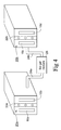
- FIGURES 1a-1c illustrate a conventional dip coating process used to deposit a coating on a substrate
- FIGURE 2 is an illustrative draw-off coating apparatus in accordance with an example embodiment
- FIGURE 3 is a flowchart showing an illustrative process for using the draw-off coating apparatus of Fig. 2 to create at least one coated article, in accordance with an example embodiment
- FIGURE 4 is an illustrative draw-off coating apparatus system in accordance with an example embodiment.
- FIGURE 5 is a flowchart showing an illustrative process for using the draw-off coating apparatus system of Fig. 4 to create a plurality of coated articles, in accordance with an example embodiment.
- a draw-off coating apparatus and/or system for depositing a coating on a substrate e.g., a glass substrate
- a substrate e.g., a glass substrate
- a method of making coating articles using the same is/are provided.
- At least one substrate to be coated is inserted into a tank.
- a liquid or sol-gel like mixture (either or both of which may have a low viscosity) is pumped into the tank in a controlled manner.
- the at least one substrate is allowed to dwell in the mixture.
- the liquid or sol-gel like mixture is drawn-off of the tank in another controlled manner.
- the drawn-off liquid or sol-gel like mixture may be provided to another tank having at least one substrate to be coated.
- a system for forming coatings on substrates may comprise two or more tanks, each said tank being configured to receive one or more substrates to be coated and each said tank comprising at least one door provided on a side thereof allowing the one or more substrates to be inserted into and/or removed therefrom; and at least one coating flow distributor configured to pump and draw-off the coating mixture between the tanks such that the levels of the coating mixture rise and fall at substantially the same or different uniform rates.
- Fig. 2 is an illustrative draw-off coating apparatus in accordance with an example embodiment.
- the draw-off coating apparatus of Fig. 2 includes a tank 20.
- the top of tank 20 may be open or closed.
- One or more substrates to be coated 10a, 10b etc. may be inserted into the tank 20.
- the one or more substrates to be coated 10a, 10b, etc. may be substantially stationary (e.g., hanged on or set in a track) once within the tank 20.
- the one or more substrates to be coated 10a, 10b, etc. do not need to be lifted to placed into or removed from the coating tank 20. Instead, they may be provided to the tank 20 through a side door 22a.
- the coating mixture (e.g., the sol-gel like mixture) may be pumped into the tank 20 through tubing 24 from a reservoir 26. More particularly, the coating mixture (e.g., the sol-gel like mixture) may be pumped into the tank 20 through tubing 24 from a reservoir 26 at a controlled speed. The coating mixture may be pumped in so as to at least partially submerge the one or more substrates to be coated 10a, 10b, etc., which may be allowed to dwell in the tank 20.
- the coating mixture e.g., the sol-gel like mixture
- the pump-in speed may be controlled so as to incrementally submerge the one or more substrates to be coated 10a, 10b, etc., at a first substantially constant rate.
- the level of the coating mixture may increase at a substantially uniform rate.
- the coating mixture may be pumped out of the tank 20 through the tubing 24 and back into the reservoir 26.
- the pump-out speed may be controlled to achieve a desired coating on the one or more substrates to be coated 10a, 10b, etc., e.g., in dependence on the relevant rheological properties.
- the pump-out speed may be controlled so as to draw-off the coating mixture relative to the one or more substrates to be coated 10a, 10b, etc., at a second substantially constant rate.
- the level of the coating mixture may decrease at a substantially uniform rate
- the first and second substantially constant rates may be the same or different.
- the newly coated one or more substrates 10a, 10b, etc. may be removed from the tank 20.
- the newly coated one or more substrates 10a, 10b, etc. may be removed from the tank 20 through the same door 22a through which it entered the tank 20, or through a separate door in the tank 20 (e.g., opposite the door 22a).
- the movement of the one or more substrates 10a, 10b, etc. may be facilitated via one or more corresponding track systems (not shown).
- the coating tanks may include a side-opening structure allowing the glass substrates to be transferred in and out from the side door(s) by a track system provided on the tank top or bottom in certain example embodiments. More particularly, in certain example embodiments, a first side-opening door may be opened when glass is transferred into the tank, and the same or a second door (e.g., on another side such as, for example, the side opposite the first door) may be opened when the substrate needs to be moved out of the tank (e.g., to the cure oven).
- a first side-opening door may be opened when glass is transferred into the tank, and the same or a second door (e.g., on another side such as, for example, the side opposite the first door) may be opened when the substrate needs to be moved out of the tank (e.g., to the cure oven).
- one or more inlet and/or outlet ports may be used to achieve the pumping-in and drawing-off of the coating mixture.
- a single port or a single group of ports may be used for both pumping-in and drawing-off the coating mixture in certain example embodiments, whereas a first port or group of ports and a separate second port or group of ports may be respectively used for pumping-in and drawing-off the coating mixture in certain example embodiments.
- the tubing 24 is shown as connecting to a side of the tank 20 in Fig. 2
- the tubing and/or associated inlet and/or outlet ports may be positioned elsewhere relative to the tank such as, for example, higher and/or lower on one or more sides of the tank 20, below the tank 20, etc.
- a coating flow distributor may be provided proximate to the tank (e.g., may be provided under the bottom of the tank) to draw-off the coating in a substantially uniform manner, thereby causing the coating surface level to drop down substantially evenly.
- the newly coated one or more substrates 10a, 10b, etc. may be transferred to a cure oven (not shown).
- the movement of the newly coated one or more substrates 10a, 10b, etc., to the cure oven also may be facilitated via the same or different one or more corresponding track systems (not shown).
- Fig. 3 is a flowchart showing an illustrative process for using the draw-off coating apparatus of Fig. 2 to create at least one coated article, in accordance with an example embodiment.
- step S31 at least one substrate to be coated is inserted into a tank.
- a sol-gel like mixture is provided to the tank at a first controlled rate until the at least one substrate inserted therein is at least partially submerged.
- the at least one substrate may be held in position in the tank as it is filled, e.g., reducing the number and/or amount of shaking and/or judder to which the at least one substrates are subjected.
- the at least one substrate is allowed to remain at least partially submerged in the sol-gel like mixture for a predetermined amount of time during step S35.
- step S37 the sol-gel like mixture is drawn-off from the tank at a second controlled rate until the at least one substrate inserted therein is no longer at least partially submerged and/or the tank is substantially free from the sol-gel like mixture.
- the at least one substrate may be removed from the tank.
- step S39 the at least one substrate optionally is cured in making the coated article. The curing may be accomplished using a cure oven in certain example embodiments.
- Fig. 4 is an illustrative draw-off coating apparatus system in accordance with an example embodiment.
- Two tanks 20a and 20b are shown in Fig. 4 , and a number of substrates to be coated 10a, 10b, 10c, 10d, etc., can be placed within the tanks 22a and 22b, e.g., through the doors 22a.
- the coating mixture is pumped out of the reservoir 26 and into one of the two tanks in a controlled manner, as described above. After the substrates 10 in the tank dwell, the coating mixture may be drawn-off of the first tank in a controlled manner and pumped into the second tank.
- the coating mixture may be drawn-off from the first tank 20a, through the tubing 24a, back into the reservoir 26, through tubing 24b, and into the second tank 20b in a controlled manner.
- This technique may be extended in certain example embodiments, such that two or more coating tanks may be connected in a like manner, thereby taking advantage of this coating delivery system.
- the pumping-in and drawing-off speeds for a particular tank may be controlled to achieve more consistent coating levels, which may based at least in part on the rheological properties of the substrates to be coated and/or the coating mixture.
- the pumping-in and drawing-off speeds may be the same or different.
- the drawing-off and pumping-in may be the same or different for each of the tanks.
- the levels of coating mixtures may be monitored in example embodiments where different speeds are used for different tanks, e.g., to compensate for different pumping-in and drawing-off speeds.
- attempting to slowly draw-off the coating mixture from a first tank or first group of tanks while quickly pumping the coating mixture into a second tank or second group of tanks may be problematic if a sufficient amount of coating mixture is not provided or already present in a reservoir.
- the levels of coating mixtures may be monitored in example embodiments, as some of the coating material may be removed with the substrates, remain in the tanks, etc.
- one or more coating flow distributors provided centrally, in groups, and/or to each of the tanks, may help ensure that the coating mixture is substantially uniformly pumped-in and drawn-off, for one or more of the tanks.
- the coating mixture may be pumped between tanks more directly, e.g., sometimes reducing or even completely eliminating the need for a coating mixture reservoir or other coating mixture source.
- Fig. 5 is a flowchart showing an illustrative process for using the draw-off coating apparatus system of Fig. 4 to create a plurality of coated articles, in accordance with an example embodiment.
- Fig. 5 is similar to Fig. 3 , except that it is corresponds to a coating system with two coating tanks rather than a single coating tank.
- step S51 at least one substrate to be coated is inserted into a first tank.
- step S53 a sol-gel like mixture is provided to the first tank at a first controlled rate until the at least one substrate inserted therein is at least partially submerged.
- the at least one substrate is allowed to remain at least partially submerged in the sol-gel like mixture provided to the first tank for a predetermined amount of time in step S55.
- At least one substrate to be coated is inserted into a second tank in step S57.
- the sol-gel like mixture is drawn-off from the first tank at a second controlled rate until the at least one substrate inserted therein is no longer at least partially submerged and/or the first tank is substantially free from the sol-gel like mixture.
- the at least one substrate is removed from the first tank in step S61.
- step S63 the sol-gel like mixture is provided to the second tank at a third controlled rate until the at least one substrate inserted therein is at least partially submerged. At least some of the sol-gel like mixture may be provided to the second tank as it is drawn off from the first tank. The at least one substrate is allowed to remain at least partially submerged in the sol-gel like mixture provided to the second tank for a predetermined amount of time in step S65.
- step S67 the sol-gel like mixture is drawn off from the second tank at a fourth controlled rate until the at least one substrate inserted therein is no longer at least partially submerged and/or the second tank is substantially free from the sol-gel like mixture.
- step S69 the at least one substrate is removed from the second tank.
- step S71 it is determined whether there are more substrates to be coated. If there are not, the process is ended. However, if there are more substrates to be coated, the process returns to step S51, and at least one substrate to be coated is inserted into the first tank. Similar to the description provided above, the sol-gel like mixture may be provided to the first tank in step S53 as it is drawn off from the second tank. As above, the substrates optionally may be cured in making the coated articles. The process may continue as normal until the process is complete.
- a system for forming coatings on substrates may comprise a plurality of tanks, with each said tank being configured to receive one or more substrates to be coated, and with each said tank comprising at least one door provided on a side thereof allowing the one or more substrates to be inserted into and/or removed therefrom; and at least one coating flow distributor configured to pump and draw-off the coating mixture between the tanks such that the levels of the coating mixture rise and fall at substantially the same or different uniform rates.
- Certain example embodiments may provide a number of advantages, e.g., as compared to conventional dip coating processes.
- the multi-tank system is conducive to producing a high product yield.
- the draw-off tank approach of certain example embodiments is conducive to creating high quality coated articles. This is related, in part, to the reduced amount of substrate vibrations and shorter time in which particle attacks may occur, both of which typically happen as the substrates are being positioned, dipped into, and/or removed from, conventional dip-coating tanks.
- the techniques of certain example embodiments may be used in a smaller clean room and production space, as compared to conventional dip coating techniques, since the substrates may be inserted and removed from the sides, rather than from the above.
- the tanks of certain example embodiments only have to be slightly larger than the glass substrates to be coated.
- the clean room, and the coating environment in general, may be maintained more easily, as it is comparatively easier to keep a closed tank clean than an entire room.
- the amount of coating evaporation may be reduced, as the coating system is substantially closed. That is, the door(s) of a tank according to an example embodiment is/are only opened as substrates are inserted and removed from the tank, as opposed to a conventional dip coating tank where the top is substantially always open. Similarly, the draw-off arrangement of certain example embodiments reduces the likelihood of concentrated coating material dripping back into coating mixture, e.g., when the substrate is removed.
- Some of these and/or other advantages conveyed by certain example embodiments help contribute to a more controllable process, where it is easier to more tightly control the coating process (e.g., as the rhelogical properties tend to be more consistent).
- a computer-controlled system may be provided in connection with certain example embodiments. Such a computer-controlled system may allow a user to program the rates at which the coating mixture should be provided and drawn-off, e.g., on a per-tank, per-system, or other basis. Similarly, such a computer-controlled system may allow a user to program the amount of coating mixture to provide to a tank (e.g., based on the size of the substrate to be coated, etc.). Also, a user may be able to program dwell times. It will be appreciated that these and/or other process conditions may be varied and/or controlled.
- a “sol” is prepared, which includes a solution or suspension in water, alcohol and/or hydroalcoholic mixtures of precursor(s) of the element(s) whose oxide(s) is/are to be prepared.
- precursors may be alkoxides, of formula M(OR) n , where M represents the element (e.g., Si) whose oxide is desired, the group -OR is the alkoxide moiety, and "n” represents the valence of M; soluble salt(s) of M such as chlorides, nitrates, and oxides may be used in place of alkoxides in certain example embodiments.
- the precursor(s) may begin to hydrolyze (with or without an acid or base catalyst), e.g., alkoxide moieties or other anion bonded to the element M(s) may be replaced by -OH groups.
- Sol-gelation may take from a few seconds to several days, depending on the chemical composition and temperature of the solution. During sol-gelation, hydrolysis of the possibly remaining precursor(s) may be completed or substantially completed, and condensation may occur including reaction of -OH group(s) belonging to different molecules with formation of a free water molecule and an oxygen bridge between atoms M, M' (which may be alike or different).
- the product obtained in this sol-gelation phase may be called alcogel, hydrogel, xerogel, or the like, or more generally "gel” as is widely used to cover all such instances.
- Gel drying then occurs; in this phase, the solvent is removed by evaporation or through transformation into gas (e.g., via heating in certain instances), and a solid or dry body is obtained.
- Densification may be performed by heat treating or curing in certain example embodiments, whereby a porous gel densifies thereby obtaining a glassy or ceramic compact oxide.
- example “sols” may be prepared in the foregoing and/or other ways, and also may be used in connection with certain example embodiments.
- coating mixtures suitable for use with certain example embodiments do not necessarily have to be sol-gel mixtures.
- draw-off coating techniques of certain example embodiments may incorporate any suitable coating mixture.
Landscapes
- Chemical & Material Sciences (AREA)
- Engineering & Computer Science (AREA)
- Organic Chemistry (AREA)
- Materials Engineering (AREA)
- General Chemical & Material Sciences (AREA)
- Chemical Kinetics & Catalysis (AREA)
- Mechanical Engineering (AREA)
- Thermal Sciences (AREA)
- Physics & Mathematics (AREA)
- Metallurgy (AREA)
- Inorganic Chemistry (AREA)
- Life Sciences & Earth Sciences (AREA)
- Geochemistry & Mineralogy (AREA)
- Ceramic Engineering (AREA)
- Dispersion Chemistry (AREA)
- Application Of Or Painting With Fluid Materials (AREA)
- Coating Apparatus (AREA)
Applications Claiming Priority (1)
| Application Number | Priority Date | Filing Date | Title |
|---|---|---|---|
| US12/232,540 US20100068404A1 (en) | 2008-09-18 | 2008-09-18 | Draw-off coating apparatus for making coating articles, and/or methods of making coated articles using the same |
Publications (1)
| Publication Number | Publication Date |
|---|---|
| EP2165772A2 true EP2165772A2 (de) | 2010-03-24 |
Family
ID=41460498
Family Applications (1)
| Application Number | Title | Priority Date | Filing Date |
|---|---|---|---|
| EP09168935A Withdrawn EP2165772A2 (de) | 2008-09-18 | 2009-08-28 | Vorrichtung zur Entfernung einer Beschichtung zur Herstellung von Beschichtungsartikeln und/oder Verfahren zur Herstellung der beschichteten Artikel damit |
Country Status (2)
| Country | Link |
|---|---|
| US (1) | US20100068404A1 (de) |
| EP (1) | EP2165772A2 (de) |
Families Citing this family (6)
| Publication number | Priority date | Publication date | Assignee | Title |
|---|---|---|---|---|
| US8596214B2 (en) * | 2009-09-29 | 2013-12-03 | Larry J. Schieszer | Wood grilling plank soaking device |
| TWI460305B (zh) * | 2010-11-30 | 2014-11-11 | Ind Tech Res Inst | 化學水浴法鍍膜設備 |
| TW201251094A (en) * | 2011-06-07 | 2012-12-16 | Hon Hai Prec Ind Co Ltd | Electrode of dye-sensitized solar cells manufacturing equipment |
| US9204982B2 (en) * | 2012-04-26 | 2015-12-08 | Medtronic Vascular, Inc. | Apparatus and methods for filling a drug eluting medical device via capillary action |
| WO2017214434A1 (en) | 2016-06-10 | 2017-12-14 | Medtronic Vascular Inc. | Drug-eluting stent formed from a deformable hollow strut for a customizable elution rate |
| US10226367B2 (en) | 2016-12-19 | 2019-03-12 | Medtronic Vascular, Inc. | Apparatus and methods for filling a drug eluting medical device via capillary action |
Family Cites Families (60)
| Publication number | Priority date | Publication date | Assignee | Title |
|---|---|---|---|---|
| US2644472A (en) * | 1951-09-07 | 1953-07-07 | American Locomotive Co | Flushing device |
| NL187797B (nl) * | 1953-06-01 | Volvo Penta Ab | Overbrengsysteem voor bootmotoren. | |
| US2808022A (en) * | 1954-05-28 | 1957-10-01 | Kaulen | Device for seamless coating of printing forms, especially of printing cylinders |
| US3664354A (en) * | 1968-11-12 | 1972-05-23 | Udylite Corp | Apparatus for processing workpieces |
| US3557749A (en) * | 1969-03-12 | 1971-01-26 | George Farago | Immersion apparatus |
| DE2330747C3 (de) * | 1973-06-16 | 1978-06-22 | Euro-Clinic-Schuck & Co, 8000 Muenchen | Desinfektions-Tauchtank |
| CH568101A5 (de) * | 1973-09-11 | 1975-10-31 | Beaud Jean Louis | |
| US4262044A (en) * | 1980-05-16 | 1981-04-14 | Kuczma Jr John J | Method for the electroless nickel plating of long bodies |
| US4438159A (en) * | 1982-03-08 | 1984-03-20 | Techsight Corporation | Coating process |
| US4767509A (en) * | 1983-02-04 | 1988-08-30 | Burlington Industries, Inc. | Nickel-phosphorus electroplating and bath therefor |
| DE3339262A1 (de) * | 1983-10-28 | 1985-05-09 | Günther Dipl.-Ing. 7778 Markdorf Boos | Vorrichtung zum transport von koerpern mittels einer in einer rohrleitung stroemenden fluessigkeit |
| US4595474A (en) * | 1983-11-14 | 1986-06-17 | Greco Bros., Inc. | Electroplating solution recovery system |
| US4911761A (en) * | 1984-05-21 | 1990-03-27 | Cfm Technologies Research Associates | Process and apparatus for drying surfaces |
| US4633893A (en) * | 1984-05-21 | 1987-01-06 | Cfm Technologies Limited Partnership | Apparatus for treating semiconductor wafers |
| US4856544A (en) * | 1984-05-21 | 1989-08-15 | Cfm Technologies, Inc. | Vessel and system for treating wafers with fluids |
| US4740249A (en) * | 1984-05-21 | 1988-04-26 | Christopher F. McConnell | Method of treating wafers with fluid |
| US4738272A (en) * | 1984-05-21 | 1988-04-19 | Mcconnell Christopher F | Vessel and system for treating wafers with fluids |
| US4795497A (en) * | 1985-08-13 | 1989-01-03 | Mcconnell Christopher F | Method and system for fluid treatment of semiconductor wafers |
| US4773983A (en) * | 1986-02-03 | 1988-09-27 | Omi International Corporation | Electrolytic apparatus and process |
| US5372701A (en) * | 1986-12-30 | 1994-12-13 | Gerdon; Louis J. | Process and apparatus for electroplating |
| JPH0634956B2 (ja) * | 1987-08-06 | 1994-05-11 | セントラル硝子株式会社 | 薄膜のコ−ティング方法およびその装置 |
| DE3731444A1 (de) * | 1987-09-18 | 1989-03-30 | Leybold Ag | Vorrichtung zum beschichten von substraten |
| US5078850A (en) * | 1989-04-10 | 1992-01-07 | Polytechs Inc. | Electrodeposition coating system |
| US5275184A (en) * | 1990-10-19 | 1994-01-04 | Dainippon Screen Mfg. Co., Ltd. | Apparatus and system for treating surface of a wafer by dipping the same in a treatment solution and a gate device for chemical agent used in the apparatus and the system |
| US5246025A (en) * | 1991-03-28 | 1993-09-21 | Cawlfield B Gene | Controlled fluid agitation method and apparatus |
| US5217533A (en) * | 1991-07-08 | 1993-06-08 | The United States Of America As Represented By The Secretary Of The Air Force | Coating apparatus for continuous fibers |
| JP2546089B2 (ja) * | 1991-07-09 | 1996-10-23 | 上村工業株式会社 | 錫又は半田めっき浴への金属イオン補給方法 |
| FR2693558B1 (fr) * | 1992-07-09 | 1994-08-19 | Commissariat Energie Atomique | Procédé de fabrication de couches minces présentant des propriétés optiques. |
| US5950645A (en) * | 1993-10-20 | 1999-09-14 | Verteq, Inc. | Semiconductor wafer cleaning system |
| US5772784A (en) * | 1994-11-14 | 1998-06-30 | Yieldup International | Ultra-low particle semiconductor cleaner |
| US5968285A (en) * | 1995-06-07 | 1999-10-19 | Gary W. Ferrell | Methods for drying and cleaning of objects using aerosols and inert gases |
| GB2302959B (en) * | 1995-06-30 | 1999-02-10 | Kodak Ltd | Carrier for photographic material |
| US5658537A (en) * | 1995-07-18 | 1997-08-19 | Basf Corporation | Plate-type chemical reactor |
| FR2738813B1 (fr) * | 1995-09-15 | 1997-10-17 | Saint Gobain Vitrage | Substrat a revetement photo-catalytique |
| EP0850203B2 (de) * | 1995-09-15 | 2012-01-04 | Rhodia Chimie | Substrat mit einer photokatalytischen beschichtung von titandioxyd und organische dispersionen mit titandioxyd |
| US5693372A (en) * | 1996-02-29 | 1997-12-02 | Xerox Corporation | Immersion coating process |
| US5720815A (en) * | 1996-03-01 | 1998-02-24 | Xerox Corporation | Dip coating apparatus having solution displacement apparatus |
| US5856018A (en) * | 1996-06-17 | 1999-01-05 | Yazaki Corporation | Plastic articles having multi-layer antireflection coatings, and sol-gel process for depositing such coatings |
| US6132522A (en) * | 1996-07-19 | 2000-10-17 | Cfmt, Inc. | Wet processing methods for the manufacture of electronic components using sequential chemical processing |
| AU6327398A (en) * | 1997-02-18 | 1998-09-08 | Scp Global Technologies | Multiple stage wet processing chamber |
| US6517894B1 (en) * | 1998-04-30 | 2003-02-11 | Ebara Corporation | Method for plating a first layer on a substrate and a second layer on the first layer |
| US6355104B1 (en) * | 1998-11-20 | 2002-03-12 | Louis S. Polster | Article treating apparatus and method and control system therefor |
| US6245250B1 (en) * | 1999-03-05 | 2001-06-12 | Scp Global Technologies Inc. | Process vessel |
| CA2270807A1 (en) * | 1999-05-03 | 2000-11-03 | Ibm Canada Limited-Ibm Canada Limitee | Closed chamber method and apparatus for the coating of liquid films |
| WO2000074111A2 (en) * | 1999-05-27 | 2000-12-07 | Lam Research Corporation | Apparatus and methods for drying batches of wafers |
| US6214419B1 (en) * | 1999-12-17 | 2001-04-10 | Xerox Corporation | Immersion coating process |
| DE10139128A1 (de) * | 2001-08-09 | 2003-02-27 | Herbert Georg Nopper | Vorrichtung und Verfahren zur Vakuumimprägnierung |
| WO2003020447A2 (en) * | 2001-08-31 | 2003-03-13 | Lord Corporation | Improved autodeposition metal dip coating process |
| US20030077396A1 (en) * | 2001-10-23 | 2003-04-24 | Lecompte Robert S. | Dip coating system |
| CN1602538A (zh) * | 2001-11-13 | 2005-03-30 | Fsi国际公司 | 用于浸渍处理的高级处理控制 |
| US20040108213A1 (en) * | 2002-12-09 | 2004-06-10 | Talasek Robert T. | Plating bath composition control |
| US7244315B2 (en) * | 2003-06-27 | 2007-07-17 | Fsi International, Inc. | Microelectronic device drying devices and techniques |
| US7157051B2 (en) * | 2003-09-10 | 2007-01-02 | Advanced Technology Materials, Inc. | Sampling management for a process analysis tool to minimize sample usage and decrease sampling time |
| US6991827B2 (en) * | 2003-11-07 | 2006-01-31 | Essilor International Compagnie Generale D'optique | Apparatus and method for dip coating lenses |
| US7108947B2 (en) * | 2003-12-19 | 2006-09-19 | Xerox Corporation | Sol-gel processes for photoreceptor layers |
| US6962626B1 (en) * | 2004-05-28 | 2005-11-08 | Xerox Corporation | Venting assembly for dip coating apparatus and related processes |
| JP4486559B2 (ja) * | 2005-07-12 | 2010-06-23 | 株式会社ムラタ | 無電解めっき液の再生装置及び再生方法 |
| US20080299411A1 (en) * | 2007-05-30 | 2008-12-04 | Oladeji Isaiah O | Zinc oxide film and method for making |
| JP4957906B2 (ja) * | 2007-07-27 | 2012-06-20 | 上村工業株式会社 | 連続電気銅めっき方法 |
| US20130087463A1 (en) * | 2011-10-05 | 2013-04-11 | Globalfoundries Inc. | Method and System for Metal Deposition in Semiconductor Processing |
-
2008
- 2008-09-18 US US12/232,540 patent/US20100068404A1/en not_active Abandoned
-
2009
- 2009-08-28 EP EP09168935A patent/EP2165772A2/de not_active Withdrawn
Also Published As
| Publication number | Publication date |
|---|---|
| US20100068404A1 (en) | 2010-03-18 |
Similar Documents
| Publication | Publication Date | Title |
|---|---|---|
| EP2165772A2 (de) | Vorrichtung zur Entfernung einer Beschichtung zur Herstellung von Beschichtungsartikeln und/oder Verfahren zur Herstellung der beschichteten Artikel damit | |
| Jeffrey Brinker et al. | Fundamentals of sol-gel dip-coating | |
| US4397666A (en) | Method of producing glass from metal alkoxide solution | |
| Puetz et al. | Dip coating technique | |
| EP1625182B1 (de) | Verfahren zur herstellung von nanostrukturierten oberflächenbeschichtung, deren beschichtungen und gegenständen enthaltend die beschichtung | |
| CN102712529B (zh) | 具有防污表面的玻璃制品及其制造方法 | |
| CN112126101B (zh) | 一种具有各向异性亲水超滑表面的制备方法 | |
| CN103288364A (zh) | 一种玻璃超疏水表面的制备方法 | |
| CN103370286A (zh) | 在基材上沉积抗反射层的方法 | |
| HK1042066A1 (zh) | 用液態或超臨界二氧化碳塗布的方法和設備 | |
| KR20130054939A (ko) | 기판 상에 정렬된 입자층의 증착 방법 | |
| CN107500561A (zh) | 高透明、超润滑、自补充性能的玻璃涂层及其制备方法和应用 | |
| WO2019131872A1 (ja) | ポリマーブラシ形成用基体及び該基体の製造方法並びに該方法に用いる前駆液 | |
| CN108913016A (zh) | 一种有机硅透明耐磨增硬涂料及其制作方法 | |
| CN111471330A (zh) | 一种亲疏水性以及表面粗糙度可调节的透明涂层及其制备方法 | |
| CN101664646A (zh) | 一种陶瓷超滤膜的制备方法及自动涂膜装置 | |
| US6277442B1 (en) | Closed chamber method and apparatus for the coating of liquid films | |
| CN105457844A (zh) | 一种液位沉降法镀膜的装置 | |
| Thomas | Optical coating fabrication | |
| Chang et al. | Fabrication of superhydrophobic silica‐based surfaces with high transmittance by using polypropylene and tetraeyhoxysilane precursors | |
| CN104311863A (zh) | 一种甲基硅树脂薄膜及其制备方法 | |
| CN114632678A (zh) | 一种pc眼镜片的加硬方法 | |
| CN1732134A (zh) | 玻璃基板上的薄膜形成方法以及薄膜被覆玻璃基板 | |
| JP2003277041A (ja) | 任意の表面特性及び表面形状を有する基体表面へのシリカ薄膜の製造方法及び複合構造体 | |
| CN207452253U (zh) | 一种薄膜材料制备装置 |
Legal Events
| Date | Code | Title | Description |
|---|---|---|---|
| PUAI | Public reference made under article 153(3) epc to a published international application that has entered the european phase |
Free format text: ORIGINAL CODE: 0009012 |
|
| AK | Designated contracting states |
Kind code of ref document: A2 Designated state(s): AT BE BG CH CY CZ DE DK EE ES FI FR GB GR HR HU IE IS IT LI LT LU LV MC MK MT NL NO PL PT RO SE SI SK SM TR |
|
| STAA | Information on the status of an ep patent application or granted ep patent |
Free format text: STATUS: THE APPLICATION IS DEEMED TO BE WITHDRAWN |
|
| 18D | Application deemed to be withdrawn |
Effective date: 20150303 |