EP2165243B1 - Flüssigkeitserwärmungsbehälter und steuerung - Google Patents
Flüssigkeitserwärmungsbehälter und steuerung Download PDFInfo
- Publication number
- EP2165243B1 EP2165243B1 EP08762397.1A EP08762397A EP2165243B1 EP 2165243 B1 EP2165243 B1 EP 2165243B1 EP 08762397 A EP08762397 A EP 08762397A EP 2165243 B1 EP2165243 B1 EP 2165243B1
- Authority
- EP
- European Patent Office
- Prior art keywords
- vessel
- temperature
- liquid
- base
- control
- Prior art date
- Legal status (The legal status is an assumption and is not a legal conclusion. Google has not performed a legal analysis and makes no representation as to the accuracy of the status listed.)
- Not-in-force
Links
- 239000007788 liquid Substances 0.000 title claims description 131
- 238000010438 heat treatment Methods 0.000 title claims description 117
- 238000009835 boiling Methods 0.000 claims description 53
- 238000005286 illumination Methods 0.000 claims description 31
- 230000003287 optical effect Effects 0.000 claims description 22
- 230000008859 change Effects 0.000 claims description 9
- 230000008878 coupling Effects 0.000 claims description 5
- 238000010168 coupling process Methods 0.000 claims description 5
- 238000005859 coupling reaction Methods 0.000 claims description 5
- 230000011664 signaling Effects 0.000 claims description 5
- 230000006854 communication Effects 0.000 claims description 4
- 238000004891 communication Methods 0.000 claims description 4
- 230000007175 bidirectional communication Effects 0.000 claims 1
- XLYOFNOQVPJJNP-UHFFFAOYSA-N water Substances O XLYOFNOQVPJJNP-UHFFFAOYSA-N 0.000 description 107
- 238000001514 detection method Methods 0.000 description 29
- 238000010586 diagram Methods 0.000 description 27
- 230000006870 function Effects 0.000 description 26
- 230000004044 response Effects 0.000 description 14
- 239000000463 material Substances 0.000 description 13
- 230000000694 effects Effects 0.000 description 10
- 229910052736 halogen Inorganic materials 0.000 description 9
- 150000002367 halogens Chemical class 0.000 description 9
- 230000005855 radiation Effects 0.000 description 8
- 238000013019 agitation Methods 0.000 description 7
- 235000014676 Phragmites communis Nutrition 0.000 description 6
- 230000008901 benefit Effects 0.000 description 6
- 230000002035 prolonged effect Effects 0.000 description 6
- 230000001954 sterilising effect Effects 0.000 description 6
- 238000004659 sterilization and disinfection Methods 0.000 description 6
- 238000010411 cooking Methods 0.000 description 4
- 230000005670 electromagnetic radiation Effects 0.000 description 4
- 230000001939 inductive effect Effects 0.000 description 4
- 238000000034 method Methods 0.000 description 4
- 230000004913 activation Effects 0.000 description 3
- 238000013459 approach Methods 0.000 description 3
- 235000013361 beverage Nutrition 0.000 description 3
- 239000003990 capacitor Substances 0.000 description 3
- 230000007423 decrease Effects 0.000 description 3
- 230000001419 dependent effect Effects 0.000 description 3
- 238000009826 distribution Methods 0.000 description 3
- 235000013305 food Nutrition 0.000 description 3
- 238000009434 installation Methods 0.000 description 3
- 230000004048 modification Effects 0.000 description 3
- 238000012986 modification Methods 0.000 description 3
- 241001122767 Theaceae Species 0.000 description 2
- 230000009471 action Effects 0.000 description 2
- 239000003086 colorant Substances 0.000 description 2
- 230000003247 decreasing effect Effects 0.000 description 2
- 239000008236 heating water Substances 0.000 description 2
- 238000009413 insulation Methods 0.000 description 2
- 238000004519 manufacturing process Methods 0.000 description 2
- 230000009467 reduction Effects 0.000 description 2
- 238000003303 reheating Methods 0.000 description 2
- 229910001220 stainless steel Inorganic materials 0.000 description 2
- 239000010935 stainless steel Substances 0.000 description 2
- 238000002604 ultrasonography Methods 0.000 description 2
- 230000000007 visual effect Effects 0.000 description 2
- NCGICGYLBXGBGN-UHFFFAOYSA-N 3-morpholin-4-yl-1-oxa-3-azonia-2-azanidacyclopent-3-en-5-imine;hydrochloride Chemical compound Cl.[N-]1OC(=N)C=[N+]1N1CCOCC1 NCGICGYLBXGBGN-UHFFFAOYSA-N 0.000 description 1
- 241001233242 Lontra Species 0.000 description 1
- 238000009825 accumulation Methods 0.000 description 1
- 230000002457 bidirectional effect Effects 0.000 description 1
- 238000009529 body temperature measurement Methods 0.000 description 1
- 235000019219 chocolate Nutrition 0.000 description 1
- 238000010276 construction Methods 0.000 description 1
- 238000001816 cooling Methods 0.000 description 1
- 238000013016 damping Methods 0.000 description 1
- 238000013461 design Methods 0.000 description 1
- 230000005684 electric field Effects 0.000 description 1
- 238000005516 engineering process Methods 0.000 description 1
- 230000001771 impaired effect Effects 0.000 description 1
- 230000006698 induction Effects 0.000 description 1
- 230000007794 irritation Effects 0.000 description 1
- 238000005259 measurement Methods 0.000 description 1
- 230000007246 mechanism Effects 0.000 description 1
- 239000002184 metal Substances 0.000 description 1
- 239000008267 milk Substances 0.000 description 1
- 210000004080 milk Anatomy 0.000 description 1
- 235000013336 milk Nutrition 0.000 description 1
- 238000012544 monitoring process Methods 0.000 description 1
- 230000001151 other effect Effects 0.000 description 1
- 230000008569 process Effects 0.000 description 1
- 230000001012 protector Effects 0.000 description 1
- 230000002441 reversible effect Effects 0.000 description 1
- 238000005096 rolling process Methods 0.000 description 1
- 235000015067 sauces Nutrition 0.000 description 1
- 238000007789 sealing Methods 0.000 description 1
- 235000014347 soups Nutrition 0.000 description 1
- 239000000758 substrate Substances 0.000 description 1
- 230000007704 transition Effects 0.000 description 1
- 238000010792 warming Methods 0.000 description 1
- 238000005303 weighing Methods 0.000 description 1
Images


Classifications
-
- A—HUMAN NECESSITIES
- A47—FURNITURE; DOMESTIC ARTICLES OR APPLIANCES; COFFEE MILLS; SPICE MILLS; SUCTION CLEANERS IN GENERAL
- A47J—KITCHEN EQUIPMENT; COFFEE MILLS; SPICE MILLS; APPARATUS FOR MAKING BEVERAGES
- A47J27/00—Cooking-vessels
- A47J27/21—Water-boiling vessels, e.g. kettles
- A47J27/21008—Water-boiling vessels, e.g. kettles electrically heated
- A47J27/21058—Control devices to avoid overheating, i.e. "dry" boiling, or to detect boiling of the water
- A47J27/21083—Control devices to avoid overheating, i.e. "dry" boiling, or to detect boiling of the water with variable operating parameters, e.g. temperature or boiling period
-
- A—HUMAN NECESSITIES
- A47—FURNITURE; DOMESTIC ARTICLES OR APPLIANCES; COFFEE MILLS; SPICE MILLS; SUCTION CLEANERS IN GENERAL
- A47J—KITCHEN EQUIPMENT; COFFEE MILLS; SPICE MILLS; APPARATUS FOR MAKING BEVERAGES
- A47J27/00—Cooking-vessels
- A47J27/21—Water-boiling vessels, e.g. kettles
- A47J27/21008—Water-boiling vessels, e.g. kettles electrically heated
- A47J27/2105—Water-boiling vessels, e.g. kettles electrically heated of the cordless type, i.e. whereby the water vessel can be plugged into an electrically-powered base element
-
- G—PHYSICS
- G05—CONTROLLING; REGULATING
- G05D—SYSTEMS FOR CONTROLLING OR REGULATING NON-ELECTRIC VARIABLES
- G05D23/00—Control of temperature
- G05D23/19—Control of temperature characterised by the use of electric means
- G05D23/1902—Control of temperature characterised by the use of electric means characterised by the use of a variable reference value
- G05D23/1905—Control of temperature characterised by the use of electric means characterised by the use of a variable reference value associated with tele control
-
- G—PHYSICS
- G05—CONTROLLING; REGULATING
- G05D—SYSTEMS FOR CONTROLLING OR REGULATING NON-ELECTRIC VARIABLES
- G05D23/00—Control of temperature
- G05D23/19—Control of temperature characterised by the use of electric means
- G05D23/20—Control of temperature characterised by the use of electric means with sensing elements having variation of electric or magnetic properties with change of temperature
- G05D23/22—Control of temperature characterised by the use of electric means with sensing elements having variation of electric or magnetic properties with change of temperature the sensing element being a thermocouple
-
- G—PHYSICS
- G05—CONTROLLING; REGULATING
- G05D—SYSTEMS FOR CONTROLLING OR REGULATING NON-ELECTRIC VARIABLES
- G05D23/00—Control of temperature
- G05D23/19—Control of temperature characterised by the use of electric means
- G05D23/20—Control of temperature characterised by the use of electric means with sensing elements having variation of electric or magnetic properties with change of temperature
- G05D23/24—Control of temperature characterised by the use of electric means with sensing elements having variation of electric or magnetic properties with change of temperature the sensing element having a resistance varying with temperature, e.g. a thermistor
-
- G—PHYSICS
- G05—CONTROLLING; REGULATING
- G05D—SYSTEMS FOR CONTROLLING OR REGULATING NON-ELECTRIC VARIABLES
- G05D23/00—Control of temperature
- G05D23/19—Control of temperature characterised by the use of electric means
- G05D23/27—Control of temperature characterised by the use of electric means with sensing element responsive to radiation
-
- A—HUMAN NECESSITIES
- A47—FURNITURE; DOMESTIC ARTICLES OR APPLIANCES; COFFEE MILLS; SPICE MILLS; SUCTION CLEANERS IN GENERAL
- A47J—KITCHEN EQUIPMENT; COFFEE MILLS; SPICE MILLS; APPARATUS FOR MAKING BEVERAGES
- A47J2203/00—Devices having filling level indicating means
-
- A—HUMAN NECESSITIES
- A47—FURNITURE; DOMESTIC ARTICLES OR APPLIANCES; COFFEE MILLS; SPICE MILLS; SUCTION CLEANERS IN GENERAL
- A47J—KITCHEN EQUIPMENT; COFFEE MILLS; SPICE MILLS; APPARATUS FOR MAKING BEVERAGES
- A47J31/00—Apparatus for making beverages
- A47J31/44—Parts or details or accessories of beverage-making apparatus
- A47J31/52—Alarm-clock-controlled mechanisms for coffee- or tea-making apparatus ; Timers for coffee- or tea-making apparatus; Electronic control devices for coffee- or tea-making apparatus
- A47J31/525—Alarm-clock-controlled mechanisms for coffee- or tea-making apparatus ; Timers for coffee- or tea-making apparatus; Electronic control devices for coffee- or tea-making apparatus the electronic control being based on monitoring of specific process parameters
-
- H—ELECTRICITY
- H01—ELECTRIC ELEMENTS
- H01H—ELECTRIC SWITCHES; RELAYS; SELECTORS; EMERGENCY PROTECTIVE DEVICES
- H01H36/00—Switches actuated by change of magnetic field or of electric field, e.g. by change of relative position of magnet and switch, by shielding
- H01H36/02—Switches actuated by change of magnetic field or of electric field, e.g. by change of relative position of magnet and switch, by shielding actuated by movement of a float carrying a magnet
Definitions
- the present invention relates to electrically powered liquid heating vessels and to electronic controls therefor.
- Electrically powered liquid heating vessels such as kettles, typically include one or more controls such as a boil control for responding to a boil condition and a dry boil control for responding to an overheat condition where there is no liquid in the appliance.
- these controls are electromechanical and comprise one or more thermal actuators and switches. Electromechanical controls are cheap to manufacture and are generally reliable, but are limited in their functions.
- Electronic controls incorporating an electronic controller such as a microprocessor and one or more electrical or electronic sensors, have been proposed as an alternative to electromechanical controls.
- Early proposals include the applicant's own patent publications GB-A-2185161 and GB-A-2228634 .
- an electronic control it would be desirable for an electronic control to be able to determine accurately the level of liquid in the vessel.
- WO-A-2008/144805 discloses a liquid heating vessel comprising a vessel body, a cordless base for providing an electrical connection to the vessel body regardless of the rotational orientation of the vessel body on the base, an electronic control and an infra-red or optical connector for the control between the vessel body and the base, the infra-red or optical connector comprising a circular or annular light guide and an infra-red or optical coupler that provides an infra-red or optical coupling with the circular or annular light guide when the vessel body is positioned on the base, regardless of the rotational orientation of the vessel body on the base.
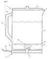
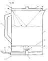
- FIG. 1 shows schematically a jug kettle with an electronic control, as an example of a liquid heating vessel to which embodiments of the invention may be applied.
- the kettle is a cordless kettle comprising a vessel body 1 and a power base 2 having respective body and base cordless connectors 3 and 4, such as 360° cordless connectors of the type described in patent publication WO-A-94/06185 and/or as sold by Otter Controls Ltd. under the CS4/CS7 (power base socket) and CP7 (appliance plug) references.
- the power base is connectable by a power cord 13 to an electrical power outlet (not shown).
- the vessel body 1 comprises a reservoir 5 for containing water to be heated, and a base section 6, as well as a spout 7, a lid 8 and a handle 9.
- Water is heated by an element plate 12 forming the base of the reservoir 5, and including a heating element on the underside (i.e. facing towards the base section 6).
- the element plate 12 may be fitted into the vessel body using the Easifix (RTM) fitting as described in WO 99/17645 .
- the element may comprise a sheathed element and/or a thick film element.
- the element plate is composed of stainless steel.
- the element plate is substantially as described in WO 06/83162 .
- at least some embodiments of the present invention are applicable to liquid heating vessels having an immersed heating element, rather than an element plate.
- the base section contains an electronic control 10 for controlling the operation state of the vessel, as will be described in more detail below.
- a user interface 11 allows the user to operate the vessel, and may provide a display of the operational state of the vessel.
- the control electronics may be divided between the user interface 11 and the control 10 as desired.
- a sensor 14 is arranged to sense the temperature of water in the reservoir 5 through the element plate 12, and is preferably thermally isolated from the heating element.
- boiling is detected by means other than temperature sensing, so that the sensor 14 is not required.
- the vessel may have one or more additional features, some of which are described in more details below. However, to avoid repetition, some of these features will be outlined here.
- Additional heating features of the vessel may include a 'keep warm' feature, in which the liquid is maintained around a predetermined temperature, preferably after boiling; this may be done by intermittent activation of the main heating element, or by intermittent or continuous activation of a secondary heating element.
- the predetermined temperature may be just below boiling point, or a lower temperature such as 80°C, and may be selectable by the user.
- Another heating feature is a sub-boil feature, in which the liquid is heated up to a predetermined temperature below boiling, such as 80°C for making coffee, and the heating power is then switched off or reduced, for example to activate a keep warm mode.
- the predetermined temperature may be selectable by the user.
- Another heating feature is a prolonged boil feature, whereby the liquid is heated to boiling and then boiled for at least a predetermined time, such as 30 seconds to 2 minutes, to sterilize the liquid.
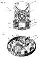
- Figures 2 to 8 show a specific embodiment of the control 10 in various stages of installation.
- Figure 2 shows a power supply and switching board 22 on which are mounted a capacitor 21 and relays 23 together with a control connector 27.
- the board 22 is mounted on a metal chassis 20, on which the cordless connector 3 is also mounted. In this way, the cordless connector 3 is integrated with the board 22 to provide an integrated component.
- FIG 3 shows the chassis 20 inverted and mounted in the base section 6.
- the reverse side of the chassis 20 carries spring connectors comprising three power connectors 24, temperature sensor connectors 25 and an overheat sensor connector 26.
- the element plate 12 has corresponding power connection pads 24', temperature sensor connection pads 25', and overheat sensor connector 26' which make electrical contact with the corresponding connectors when the element plate 12 is located on the chassis 20, as shown in Figures 5 and 6 .
- the element plate 12 also includes temperature sensor mounting pads 28 to which the temperature sensor 14 (shown in dotted outline in Figure 4 ) is connected.
- the temperature sensor 14 is located in a central portion of the element plate 12 which is free from thick film heating tracks, so that the sensed temperature is close to that of the water during heating, although there is some heat conduction from the surrounding heating tracks to the sensor 14 via the element plate 12.
- the element plate 12 preferably comprises a stainless steel substrate and an insulating layer on which the heating tracks are deposited.
- the temperature sensor 14 preferably comprises an NTC thermistor.
- the element plate 12 comprises a high power heating track 29 and a low power heating track 30, which are independently switchable via separate high and low power connection pads 24'.
- the high power track 29 is rated at 2073 W and the low power track at 1027W, giving a maximum power of 3.1 kW when both tracks are powered in parallel.
- the overheat sensor connector 26' is used to detect leakage current which is indicative of an overheat condition of the element plate 12, as described in WO 06/83162 .
- the control 10 can detect a dry boil condition and/or scale deposit.
- FIG 7 shows the user interface 11 in this embodiment, which is connectable to the control connector 27 on the power and switching board 22 by a control cable 32.
- the user interface portion comprises user actuable buttons 34, and an LCD display 36, as well as a lighting connector 38 and an audio connector 40.
- the user interface 11 may be provided in the handle 9 so that the display 36 and buttons 4 are easily accessible to the user.
- the user interface 11 includes a microprocessor arranged to control operation of the vessel by means of the power and switching board 22, in response to user control by means of the buttons 34.
- the microprocessor also controls the display 36, as well as lighting effects via the lighting connector 38 and audio via the audio connector.
- the user interface 11 may be movably mounted so that its position or configuration can be altered to suit the user.
- the display 36 may be pivotable and/or rotatable so that it is more easily visible when the vessel body 1 is separated from or connected to the base 2.
- the display 36 may be pivotable about a substantially vertical axis and mounted on the lid or upper surface of the vessel, so as to be configurable for left or right-handed operation.
- Figure 9a is a circuit diagram of the power supply and switching board 22, showing the connection of the relays 23 to the power connectors 24.
- the capacitor 21 forms part of a power supply that supplies a low DC voltage on the control connector 37 from the mains AC power.
- Figure 9b is a circuit diagram of an interface circuit for providing the voltages necessary to drive the relays 23 and the lighting connector 38.
- This interface circuit forms part of the user interface 11, although it could alternatively be located within the base section 6.
- Figure 9c is a circuit diagram of the connection of the microprocessor to the temperature sensor and overheat sensor inputs. The diagram also shows the connection of the user actuable buttons 34.
- Figure 9d is a circuit diagram of the LCD driver circuit for driving the LCD display 36.
- the microprocessor includes a program memory in which one or more control programs are stored for performing one or more control functions, as described below.
- the control program may be stored in program memory during manufacture.
- the control program is stored in flash memory and may be updated via an interface to the microprocessor and/or the program memory.
- the interface may be an external interface such as a USB port, to allow programs and/or data to be transferred to the control.
- the external interface may be a wireless interface, such as a Bluetooth (RTM) interface.
- the control is arranged so that the high-voltage circuits, such as the power supply and the relays, are formed within the base section, close to the element plate 12 and the cordless connector 3.
- the low voltage electronic circuits form part of the user interface section, which is remote from the element plate 12.
- the low voltage electronic circuits are more susceptible to heat and moisture, so it is advantageous to locate them away from the base section 6.
- At least the power switching components of the control are located in the power base 2 and are controlled via the cordless connectors 3, 4.
- the control may send a low voltage pulse on the earth pin of the cordless connector 3, which controls the switch to toggle the power.
- signalling between the vessel body 1 and the cordless base 2 may be simplified.
- the power switching components are further removed from the control logic, so that the risk of interference is reduced.
- Data and/or signals may be communicated between the body 1 and the base 2 wirelessly, for example via infra-red or optical signalling.
- One of the body 1 and/or the base 2 may include a circular light guide 2a concentric with the cordless connector, with a corresponding infrared transmitter and/or receiver 1a at the same radius, as shown schematically in Figure 10 , so that communication may occur regardless of the relative orientation of the body 1 on the base 2.
- the user interface 11 may be provided as a remote control device, connected wirelessly to the control 10, for example by an infrared (IR), sonic, ultrasonic or radio frequency (RF) link.
- IR infrared
- RF radio frequency
- IR infrared
- sonic sonic
- RF radio frequency
- Known wireless technologies and/or protocols may be used for the wireless link, such Bluetooth®, or IR signalling protocols similar to those used in remote control devices for audiovisual equipment; in this way, the vessel may be controlled by a suitably programmed remote control device for audio or audiovisual equipment.
- a person watching television need not get up to switch on the kettle, but may instead switch on the kettle using an existing television IR remote control, provided there is a line of sight to the kettle, or using an RF remote control.
- the vessel is remotely controlled by sonic signals, the user may switch on the kettle without the need for a remote control device, simply by whistling for example.
- a remote control user interface 11 for a liquid heating vessel has ecological advantages. For example, users often fill a kettle and set it to heat up or boil, in the expectation of needing hot water for cooking or making beverages in the near future. Much energy is wasted as the water cools down before it is needed, or is kept warm for too long. With a remote control, the user may switch on the kettle shortly before hot water is needed, while performing other tasks.
- the user interface 11 may control heating functions in addition to switching the heating function on and off. For example, the user interface may control the target heating temperature and/or 'keep warm' temperature. The user interface 11 may control additional heating features of liquid heating vessel, as described above. The user interface 11 may control auxiliary features of the liquid heating vessel not directly involving heating, such as lighting effects. In a reservoir vessel, such as a filter kettle or an 'ECO' kettle as described in EP-A-1289395 , the user interface 11 may control a valve for admitting water or other liquid from a reservoir into a heating chamber. The user interface 11 may control other functions, such as lid opening mechanisms, spout flaps, filling aids and pouring aids. Features of the remote control user interface are applicable to other appliances, such as coffee makers, flow-through heaters, teawakers and the like. The user interface 11 may be programmable and include a timer, so that the user can set desired actions at specific times.
- the link to the user interface 11 may be bidirectional, so that information regarding the status of the vessel may be sent from the control 10 to the user interface 11.
- the status may be displayed to the user and/or used to trigger a further control signal by the user interface 11.
- the user interface 11 may be programmed to activate a 'keep warm' mode or a prolonged boil or simmer mode after the liquid has reached the required temperature.
- the prolonged boil or simmer mode the user may set the duration of this mode; for example, the user may set a 1 minute prolonged boil for sterilization, or a 10 minute simmer for cooking, where the vessel body 1 is suitable for cooking foods in water or other liquid.
- a first alert may be sent to the user interface 11 when the liquid has reached boiling, and the interval timer may then be started by a further user actuation, for example after the user has added the food to the liquid. When the interval has expired, the user is alerted again to drain the cooked food.
- control 10 may detect whether the body 1 is connected to the base 2, or whether power is available, and indicate this status to the user interface 11 so that the user knows whether heating functions are available.
- control 10 may indicate the level of liquid in the vessel, so that the user knows whether heating can be activated, or the vessel needs to be refilled.
- Other status or condition indications may include the sensed water temperature, the estimated time to reach target temperature (sub-boil or boil), whether the vessel needs descaling, whether the vessel has dry boiled, time since last filling etc.
- the user interface 11 may be removably mountable on the vessel body 1 and/or the power base 2, and may be rechargeable by an electrical or inductive coupling thereto.
- the control 10 may only be operable by means of the user interface 11, such that if the user interface 11 is removed, the control 10 is not manually operable; this may provide an advantageous child safety feature.
- the user interface 11 may be mountable over a manual actuator for the control 10, so that the latter is only accessible when the user interface 11 is removed.
- the user interface 11 may provide touch-sensitive control, but may be removed if the user prefers mechanical control.
- the control 10 may be manually actuable independently of the user interface 11.
- the remote control user interface 11 may be arranged to communicate with an intermediate module 11a that communicates in turn with the control 10.
- the intermediate module 11a may act as a simple relay between the remote control 11 and the control 10, or may provide additional data for the control 10, such as sensing barometric pressure, that do not require input from the user.
- the intermediate module 11a may communicate wirelessly with the control 10, using a similar or different form of wireless communication to that used by the user interface 11.
- the intermediate module 11a may be a fixed installation and therefore may communicate with the control 10 using a wired connection, such as via mains signalling; this is particularly advantageous since the vessel must be connected to the mains in order to operate.
- the intermediate module 11a may be arranged to communicate with one or more additional electrical devices other than the liquid heating vessel, such as lighting, heating or other devices.
- the intermediate module 11a may be a control hub for a wireless domestic control system.
- the intermediate module 11a is operatively connected to entertainment equipment to synchronise the operation of the vessel with the condition of the entertainment equipment.
- the intermediate module 11a may detect that a commercial break in a television program is about to commence, and may automatically switch on the vessel so that the water therein is boiled approximately when the commercial break commences. This may be done by coupling the intermediate module 11a to the television receiver, so as to detect an embedded signal in the television programming indicating the approach of a commercial break; similar functionality is known in VCR's, for pausing recording during commercial breaks.
- the intermediate module 11a may retrieve electronic program guide data from the receiver, or from another source such as the Internet, determine when the currently watched program at the receiver is about to end, and activate a heating function of the vessel a predetermined time before the end of the program.
- the intermediate module 11a may communicate with the user by other means than via the user interface 11.
- the intermediate module 11a may communicate with an entertainment system to notify the user of a specific state or condition of the vessel.
- the intermediate module 11a creates a short signal that generates audible or visible interference at the entertainment system, so as to alert the user, or generates a low power radio signal that is output as an audible message by a radio receiver.
- the intermediate module 11a may send a text message or email to notify the user, via a corresponding SMS or email interface within the module 11a.
- the intermediate module 11a may contain the control 10 for the vessel, and may receive information from one or more sensors in the vessel and send commands to switching circuitry within the vessel body 1 and/or the power base 2.
- the intermediate module 11a is arranged to sense remotely properties of the vessel and/or its contents, and to control the switching state thereof.
- the vessel may contain a temperature sensor which transmits a signal representing the sensed temperature.
- the intermediate module 11a may include a remote sensor, such as an infrared sensor or force sensor as described below, which senses the condition of the vessel, such as the temperature of a part of the vessel or agitation of the liquid within the vessel.
- the intermediate module 11a may determine a boil or sub-boil condition of the vessel from the sensed temperature, and control the heating state of the vessel in response to the determined condition thereof.
- the intermediate module may include a control program, such as described in the section Boil Detection and/or Sub-boil Temperature Detection below.
- the intermediate module 11a may be reprogrammable, for example by loading an updated control program via a local network connection or via the Internet.
- the intermediate module 11a may be provided in a mains plug for connecting the vessel to mains power, or in an adaptor module connected between the mains plug and the socket, and may switch power to the vessel.
- the intermediate module 11a may communicate with the control 10 through the mains cable between the module 11a and the control, either by signals transmitted through the mains wiring, or via a separate electrical or optical connection within the mains cable sheath.
- This arrangement of the intermediate module may be retrofitted to an existing vessel with little or any modification to the vessel, or may be used with a vessel having very few electrical or electronic components fitted within the vessel itself.
- the user interface 11 as a remote control unit provides greater choice in the design of user interface 11.
- the user interface 11 may be designed for operation by a disabled user, for example with large buttons for users with poor motor skills or Braille labels for visually impaired users.
- users may choose a user interface 11 to suit their needs, without the need for the manufacturer to provide different vessels for different user interface requirements.
- the basic functions for the electronic control of a liquid heating vessel may comprise:
- liquid heating vessel Further optional functions of the liquid heating vessel include:
- the liquid heating vessel may comprise one or more of the following optional discrete components:
- Table 1 Function user control sensing switching control status display additional switching Component body 1 Yes Yes Yes Yes Yes Yes power base 2 Yes Yes Yes Yes Yes Yes Yes Yes module 11a Yes Yes Yes Yes Yes Yes Yes No remote 11 Yes No No Yes Yes No
- the user control and/or status display may be provided in any one or more of the components, although if the remote 11 is present, it must contain at least one of these functions. Sensing and switching are not practicable for the remote 11, as this needs to be mobile with respect to the vessel body 1.
- the control logic may be implemented in any one or more of the components, and may be distributed between the components. Switching of additional vessel functions may only be performed within the power base if there is a separate power supply for the additional functions from the power base 2 to the vessel body 1.
- a power source such as a battery or capacitor, may be provided in the vessel body 1 to provide power to the electronic circuits when the vessel body 1 is removed from the power base 2.
- the power source is rechargeable and is recharged when the vessel body 1 is connected to the power base 2.
- the power source may be charged when the vessel body is not connected to the power base 2, for example by a photovoltaic panel on the vessel body 1.
- the power source may preserve the state of at least some parts of the electronic control 10, and may be sufficient to power lighting or other effects as described below.
- the user may operate the user interface 11 while the vessel body 1 is removed from the power base, for example to change settings such as control settings and/or lighting.
- the user interface 11 may be operable in a demonstration mode, to demonstrate non-heating features of the vessel when the vessel is not plugged into the mains.
- the vessel should preferably be chargeable without a mains connection, such as by means of a photovoltaic panel, or the power source should be renewable.
- the electronic control 10 may enter a standby mode when the vessel body 1 is separated from the base 2 for more than a predetermined interval.
- the power drain may be reduced by switching off lighting and/or disabling features of the user interface 11.
- the vessel body 1 may leave standby mode in response to being reconnected to the base 2 and/or in response to user control via the user interface and/or in response to other inputs, such as from a user proximity sensor.
- the electronic control 10 may enter a mode that is not a low power mode, but is intended to encourage the user to replace the vessel body 1 on the base 2.
- the control 10 may detect the charging level of the power source within the vessel body 1, and issue an alert to the user when the charging level is below a predetermined level.
- the control 10 may alert the user when the vessel body 1 has been separated from the base 2 for more than a predetermined interval, to ensure that the vessel body 1 is not misplaced or unavailable when the user next wants to use the vessel.
- a boil detection control program is arranged to perform the algorithm shown in Figure 14 .
- an initial boil operation for example the first boil operation that is performed by the user
- the water is heated until boiling is detected (S2) using an initial boil detection algorithm.
- One such algorithm measures the rate of temperature rise of the water, and detects boil when the rate falls below a predetermined value, as described for example in GB-A-2228634 . This algorithm gives a reliable indication of boiling, but is comparatively unresponsive.
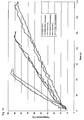
- the present inventors have found that the sensor temperature recorded when the rate of temperature rise falls below the predetermined value varies with the rate of temperature rise during heating: when the rate of rise is low, for example because of a large water volume or a low power input, the recorded sensor temperature at boiling is lower than when the rate of rise is high.
- Figure 15 shows the water temperature (measured by thermocouples within the water) and NTC sensor temperature at three different rates of temperature rise; in this case when heating 500 ml, 1100 ml and 1700 ml of water to boiling.
- the sensor temperature lags behind the water temperature, while at a low rate of rise, the water temperature lags behind the sensor temperature; this is due to the thermal inertia of the heating element relative to the thermal inertia of the water being heated.
- the average rate of temperature rise is determined between the starting temperature and a predetermined temperature, such as 90°C. Boiling is then detected when the rate of temperature rise falls below 0.1 °C/s, and the boiling temperature T B is then recorded.
- the measured boiling temperature T B varies according to the volume of water in the vessel, which is approximately inversely proportional to the average rate of temperature rise up to the predetermined temperature, assuming constant heating power and negligible heat loss.
- the boiling temperature T B is therefore adjusted for a nominal average rate of temperature rise corresponding to a nominal volume of water, and the adjusted temperature is recorded as the boil reference temperature T BR (S3).
- the boil reference temperature T BR may be reduced by a small amount, such as 1°C, to compensate for the delay in the initial boil detection algorithm.
- the user may be required to fill the vessel with the nominal volume of water for the initial boil operation, in which case the boiling temperature is taken as the boil reference temperature T BR without adjustment.
- the boiling temperature is taken as the boil reference temperature T BR without adjustment.
- this approach relies too much on the accuracy of the user, and is less preferred.
- ⁇ T/ ⁇ t the average rate of temperature rise up to a predetermined temperature is measured as ⁇ T/ ⁇ t, where ⁇ T is the difference between the start temperature and the predetermined temperature (such as 90°C), and ⁇ t is the time taken to reach the predetermined temperature from the start temperature.
- a target boil temperature T T is then calculated (S6) as a function of the boil reference temperature T BR and ⁇ T/ ⁇ t, to compensate for the difference between ⁇ T/ ⁇ t and the nominal average rate of temperature rise corresponding to the nominal volume of water.
- the program checks whether boil is detected according to the initial boil detection algorithm (S7). If so, then a boil condition is determined (S9). If not, the program checks whether the measured temperature T has reached the target boil temperature T T (S8) and if so, the boil condition is determined (S9); otherwise, heating continues and the boil detection algorithms are repeated (S7, S8) until the boil condition is determined (S9).
- heating may be terminated or reduced, for example to keep the water warm at a temperature below boiling, to boil the water at reduced power for a predetermined period for sterilization, or to simmer the water or other liquid in the vessel.
- the boil detection algorithm based on the target temperature T T (S8) is more responsive than the initial boil detection algorithm (S2, S7), since the latter depends on temperature measurement over a period of time in order to determine when the rate of rise has fallen below the threshold; this period of time should be long enough to achieve reliable boil detection, even for the maximum volume of water and/or low heating power, when the rate of temperature rise is at its lowest.
- the initial boil detection algorithm is included for subsequent boil operations (S7) as a check in case the target temperature T T algorithm fails. This may occur if the atmospheric pressure has reduced since the boil reference temperature T BR was measured, for example if the vessel has been taken to a higher altitude.
- the boil detection control program may adjust the boil reference temperature T BR after a boil condition is determined (S9).
- the program compares the actual temperature T B at which boil was determined with the target temperature T T . If T B ⁇ T T , for example because boil was detected by the initial boil detection algorithm first (S7), then the boil reference temperature T BR is decreased by a small predetermined quantity, such as 0.05°C.
- information about the ambient pressure and/or altitude of the vessel may be input to the control, for example by entering the information via the user interface 11 or intermediate module 11a, or by inputting data from an external device via the external interface, such as from an electronic barometer or from a GPS device.
- the average rate of temperature rise ⁇ T/ ⁇ t is used to calculate the time ⁇ T 1 to increase the water temperature by a first predetermined amount ⁇ 1 , such as 2°C. This may be done as an additional part of step S6.
- the program sets a timer for the interval ⁇ T 1 .
- the condition at step S8 becomes T > T T - ⁇ 2 .
- the timer is set if the condition is satisfied.
- the boil condition is determined (S9) in response to expiry of the timer; in other words, the boil condition is determined an interval ⁇ T 1 after the condition at step S8 is satisfied.
- the actual boil temperature T B may be higher than the target temperature T T , for example because of scale accumulation on the element plate 12. If T B > T T , the boil reference temperature T BR is increased by a small predetermined quantity, such as 0.05°C. This allows the program to track the effect of scale deposit. Furthermore, the current value of the boil reference temperature T BR may be used to detect excessive scaling: if the boil reference temperature T BR exceeds a predetermined threshold, then a scale warning may be indicated to the user or an automatic descaling process may be initiated, for example as described below.
- the boil reference temperature T BR may be too high, and the initial boil detection algorithm may detect boiling before the target temperature algorithm i.e. T B ⁇ T T .
- the boil reference temperature T BR will then be decreased by a small predetermined quantity, such as 0.05°C after each boil operation until T B > T T .
- the control program may decrease the boil reference temperature T BR by a larger quantity if T B is significantly less than T T , so that the control program adjusts more quickly to descaling.
- the value of T BR may be reset, for example by performing a new initial boil operation (S1) and calculating the new value of T BR from the boil temperature T B (S2, S3).
- the reset may be performed periodically, such as after every 1000 heating operations, or in response to a user actuation.
- a control program for heating the liquid up to a predetermined temperature lower than boiling may be a fixed temperature, such as 80°C which is suitable for brewing coffee, or may be set by the user at a desired temperature.
- the liquid When liquid is heated from ambient temperature in a liquid heating vessel, the liquid is not thoroughly mixed until it reaches boiling point.
- the local water temperature may vary by as much as 20°C, whereas at an average temperature of 95°C the local variation may have fallen to 5°C.
- measuring average water temperature for a sub-boil temperature presents problems that do not exist for temperatures close to boiling.
- the sensor 14, which is located at the bottom of the column of water in the reservoir 5, will sense a temperature higher than the average temperature of the water.
- the local temperature variation is dependent on the volume of liquid in the vessel. For a smaller volume, the temperature variation will be less. For a given measured temperature at the bottom of the vessel, the average temperature will therefore be higher for a smaller volume.
- the volume of liquid is determined indirectly by measuring the rate of temperature rise, which is approximately inversely proportional to volume for a constant heating power.
- the rate of temperature rise ⁇ T/ ⁇ t is measured as the liquid is heated from a starting temperature to a temperature below the desired sub-boil temperature for the water.
- the target sensor temperature is then adjusted according to the measured rate of temperature rise ⁇ T/ ⁇ t, so that the average temperature corresponds to the desired sub-boil temperature when the measured sensor temperature reaches the target temperature. Heating is then terminated, or reduced to keep the water at the desired sub-boil temperature. In the latter case, the sensor temperature may change as the water becomes more thoroughly mixed and the sensor temperature approaches the average temperature of the water.
- the initial water temperature before heating may have an effect on the actual average water temperature when the sensor temperature reaches the target sensor temperature, adjusted as described above.
- the initial water temperature is measured and the target sensor temperature is adjusted according to the measured initial water temperature.
- the heater may be controlled to maintain the water around the desired temperature, whether just below boiling or the desired sub-boiling temperature.
- the control program may switch the element on when the measured water temperature falls a predetermined amount below the desired temperature, until the desired temperature is reached.
- the target temperature T T corresponding to the desired temperature may be adjusted according to the rate of rise of the water temperature ⁇ T/ ⁇ t as the water is reheated, similarly to the boil and sub-boil detection algorithms described above.
- the keep warm mode may be maintained indefinitely, until the user switches it off.
- the control program may switch off the keep warm mode automatically after a predetermined period, such as 30 minutes.
- the keep warm mode may be used as a simmer control, to maintain the liquid around boiling without producing a fast, rolling boil.
- This simmer control may be applied to liquid heating vessels other than kettles, which are suitable for cooking.
- the control program may be operated in sterilization mode, in which the water is boiled for a predetermined period (such as 15 seconds). In this mode, it is not essential to use the target temperature algorithm to detect boiling, as a prolonged boil is required and a rapid response to boiling is unnecessary. Instead, the initial boil detection algorithm may be used. A timer is set for the predetermined period, and the heater is then switched off.
- the sterilization control mode may include a desired temperature indication mode. After the heater is switched off, the water cools and the control program senses the water temperature until it reaches a target temperature corresponding to the desired temperature, at which point the control program provides an indication to the user that the desired temperature is reached. Additionally, the control program may then enter the keep warm mode to keep the sterilized water at the desired temperature. The user may select the desired temperature indication mode and/or the keep warm mode in addition to the sterilization mode.
- a bimetal used as a dry boil sensor is typically arranged to be in good thermal contact with an element plate until activated, at which point the bimetal snaps out of contact with the element plate, and is therefore able to cool down and reset quickly.
- a bimetal used as a steam sensor may be arranged in a steam chamber or adjacent the outlet of a steam tube. When the steam sensor is activated, steam is no longer generated and so the quantity of steam around the sensor decreases rapidly; the sensor therefore cools and resets quickly.
- the senor 14 is an electrical or electronic sensor and does not move out of thermal contact with the element plate 12 when the target temperature or dry boil condition is detected. Hence, the sensed temperature remains high for some time after power to the element plate 12 is switched off or reduced, due to the thermal inertia of the element plate 12, unlike the rapid cooling of mechanical sensors.
- the control 10 enters an override mode in response to user actuation to reheat the liquid when the sensed temperature is still above the target temperature T T .
- the control 10 switches on or increases heating power for a predetermined time, such as 10 seconds, and then switches off or reduces power.
- the override mode also has the benefit of reassuring the user that the vessel is still operational; otherwise, a user accustomed to the rapid resetting of manual sensors may assume incorrectly that the vessel is faulty.
- the volume of water in the reservoir 5 may be detected by means, as described below.
- the control 10 is connected to a series of reed switches 42 at approximately equally spaced heights within a vertically extending tube 46 within the reservoir 5.
- a magnetic float 44 is slidably mounted on the outside of the tube 46 to actuate the reed switch or switches 42 closest to the float. In this way, the control 10 may determine the liquid level, and hence derive the volume of liquid in the reservoir, by determining which reed switches are actuated.
- the tube 46 may be a steam tube for conveying steam to the control 10.
- the reed switches 42 may be arranged within the wall of the reservoir 5, or outside the wall but within a housing, such that they can still be actuated by the magnetic float 44.
- the reed switches 42 may be replaced by sensors within the reservoir 5, such as electrodes that are able to detect whether they are immersed, in which case there is no need for the magnetic float 44.
- sensors within the reservoir 5 such as electrodes that are able to detect whether they are immersed, in which case there is no need for the magnetic float 44.
- capacitive level sensors may be used.
- the liquid level is sensed by means of a pressure sensor at or near the bottom of the reservoir 5. As the liquid level increases, so does the sensed pressure, from which the liquid level is derived.
- the liquid level or volume is detected by sensing the electrical resistance of the liquid in the reservoir 5. Assuming the conductivity of the liquid is constant, the resistance of the liquid as a whole will decrease as the level or volume increases. The resistance may be measured between electrodes, one of which is preferably arranged at the bottom of the reservoir 5. Alternatively, liquid level or volume is detected using a capacitive sensor or sensors.
- the liquid level is sensed by an ultrasonic transducer 48 coupled to the element plate 12.
- Ultrasonic pulses are reflected off the surface of the liquid and are detected by the transducer 48.
- the control 10 measures the time taken for the pulses to be reflected off the surface and thereby calculates the distance of the surface from the element plate 12 and therefore the liquid level.
- the transducer 48 could be located above the surface of the water, such as in or adjacent to the lid 8, and the level of the surface thereby determined and used to calculate the liquid level.
- the control 10 varies the frequency of the ultrasonic transducer and determines the amplitude of the reflected signal at the different frequencies and hence a resonant frequency or frequencies.
- the reflection of the ultrasound between the element plate 12 and the surface will determine a resonant frequency in the liquid having a wavelength that is a function of the distance between the surface and the element plate.
- the speed of sound in water is approximately 1500 m/s, therefore a frequency above 20 kHz will give a wavelength of 7.5 cm, which is comparable to the depth of water in a kettle.
- the control 10 therefore derives the liquid level from the resonant frequency or frequencies.
- the resonant frequency may alternatively be a resonant frequency of part or all of the vessel body 1, such as the resonant frequency of the walls.
- the amplitude of the resonance will be damped according to the volume of water in the vessel.
- the frequency of the ultrasound is fixed, and the amplitude of the resonance is detected to determine the water level or volume.
- an electrical signal at an ultrasonic frequency may be passed through the heating element itself, or through a separate track on the element plate; the electrical signal interacts with the earth's magnetic field to cause ultrasonic vibrations within the element plate. It has been observed that passing 50 Hz mains current through a thick film element can cause audible vibration of an element plate; this effect, which is normally considered as a nuisance to be avoided, is harnessed in the present embodiment by the use of ultrasonic signals.
- an electromagnetic signal such as a light signal may be used; the light may be laser light.
- the electromagnetic signal may be emitted as a short pulse, or series of pulses, which is reflected off the surface of the liquid and detected by a photodetector.
- the time of flight may be measured using conventional components such are used in laser distance meters, and used to calculate the liquid level.
- a distance-measuring device 48 is situated at or around the top of the reservoir 5.
- the device may be a laser or ultrasonic distance measuring device.
- the distance-measuring device 48 may be positioned substantially on the central vertical axis of the reservoir 5, so that the accuracy of the water level accuracy measurement is not dependent upon the vessel body 1 being vertical.
- the distance measuring device(s) may be used to accurately measure the level of water during filling at the tap, when the vessel body 1 is likely to held at an angle.
- the distance-measuring device may be positioned outside the water reservoir of the vessel, and may be directed at the water surface through a window.
- the signal may be substantially continuous but modulated to provide a timing reference.
- the signal may be pulse modulated.
- electromagnetic radiation or ultrasonic vibration may be directed obliquely at the surface of the liquid, and a detector is positioned to detect the radiation or vibration reflected off the surface. At the liquid level changes, the amplitude of the detected radiation or vibration changes, and the level is detected therefrom.
- the volume of liquid in the reservoir 5 is detected by weighing the reservoir, for example using a force sensor 51 in the body 1 or in the base 2.
- the force sensor 51 may comprise a strain gauge or other electrical, electronic or optical force detecting component arranged to measure the force between the body 1 and the base 2.
- the force sensor is calibrated to compensate for the weight of the body 1; since the liquid has a known density, the volume of liquid is proportional to the measured weight.
- the force sensor 51 may be used to detect whether the body 1 is on the base 2, by determining whether the detected force is less than the calibrated weight of the body 1.
- a pressure switch or light sensor may be used instead.
- the light sensor may be provided in the base 2, and be arranged to be occluded when the body 1 is located on the base 2.
- the force sensor may be used to detect whether a user is touching the body 1, by detecting the resultant change in force between the body 1 and the power base 2.
- the force sensor 51 may be used as part of a touch sensitive user control.
- the force sensor may be used to detect agitation of the liquid within the reservoir 5, caused by simmering and/or boiling of the liquid.
- the agitation causes small characteristic fluctuations in the force between the vessel body 1 and the power base 2, which may be sensed by the force sensor 51 and used by the control 10 to detect simmering and/or boiling.
- a force sensor 51 for boil detection may provide a particularly advantageous arrangement in which the number of electrical components within the vessel body 1 is reduced to a minimum.
- the switching and control functions may be located in the power base 2 and/or an intermediate module 11a, if present.
- Boil sensing may be provided by a force sensor located within the power base 2.
- the electrical components within vessel body 1 need only comprise the element plate 12 and the cordless connector 3, and a dry boil protector if required by safety standards.
- the cordless connector 3 may be a washproof cordless connector as described for example in WO08/012506A1 , so that the vessel body is washable in a dishwasher, and is particular suitable for heating liquids other than water.
- the vessel body is heated inductively by an induction heater 52 located within the power base 2, and boiling of the liquid is sensed by a force sensor 51 arranged within the power base and arranged to sense the force applied by the vessel body 1 onto the base 2.
- a force sensor 51 arranged within the power base and arranged to sense the force applied by the vessel body 1 onto the base 2.
- a user interface 11 may be provided in the base 2, or as a remote control.
- Dry boil protection may be provided by selection of the material and/or structure of the inductively heatable portion so as to provide a Curie temperature above the normal temperature of the inductively heatable portion during heating, but below the point at which dry boiling would cause damage to the vessel body.
- dry boil protection may be provided by self-regulation of the temperature of the inductively heatable material.
- dry boiling may be sensed in the power base by detecting a change in the inductive coupling between the inductive heater and the inductively heatable material, caused by a rise in temperature of the latter.
- the force sensor may be provided in the vessel body 1 and be arranged to detect the force between the body 1 and a surface on which the body 1 rests.
- Scale deposit on the element plate 12 may alter the resonant properties of the element plate, and may in particular damp the resonance or alter the resonant frequency of the element plate.
- the control 10 may detect scale deposit on the element plate 12 by inducing ultrasonic vibration of the element plate at a nominal resonant frequency thereof, detecting the amplitude of the vibration, and determining the existence of scale deposit from the amplitude of the vibration. Reduced amplitude at the resonant frequency may indicate damping and/or a shift in resonant frequency and therefore the presence of scale on the element plate.
- At least some of the level sensors or sensing techniques described above may be used to detect the level or volume of liquid remaining in a liquid heating vessel after the liquid has been heated, some of the liquid has been dispensed, and the vessel is returned to its normal position, such as a kettle being returned to its cordless connector base.
- the liquid remaining in the vessel after heating and dispensing may indicate that the liquid heating vessel is not being used efficiently, as it was filled with more liquid than was needed.
- the control measures the quantity of water heated during a heating operation, and the quantity of water remaining after the vessel body 1 is returned to the power base 2, for example following a dispensing operation.
- the ratio of remaining water to heated water is calculated and used to determine an efficiency rating which is indicated to the user as a measure of how efficiently the vessel is being used. This indication may be made every time the vessel body 1 is returned to its power base 2, or only if the efficiency rating is low i.e. the ratio of remaining water to heated water is high.
- the control may calculate an average efficiency rating, for example based on the average ratio of remaining water to heated water over the last 10 operations, or some other number of operations.
- At least some of the level sensor or sensing techniques described above may be used to detect the level or volume of liquid in a liquid heating vessel on or before commencement of a heating operation, to determine whether the liquid level is above a predetermined maximum and/or below a predetermined minimum level; if not, the heating operation may be inhibited, or an indication given to the user. In this way, unsafe operation of the vessel may be prevented.
- the predetermined maximum and/or minimum may be set according to the operational parameters of the vessel, for example to correspond to maximum and minimum levels for safety purposes, or may be altered by the user, for example if a user wants to save energy by never heating more than a particular volume of water.
- the vessel body 1 may include a rechargeable power source so that the control may perform level detection when the vessel body 1 is removed from the base 2.
- the predetermined level may be set by the user, for example by means of the user interface 11. Preferably, this setting may be changed even when the vessel body 1 is removed from the base 2. For example, the user may select between two or more predetermined levels, such as full (e.g. 1.7 litres), ecological (1 litre), or single cup. If the predetermined level is exceeded, the user interface 11 may give the user the option to change to a higher level and continue filling, or empty out some of the water until the current level is reached.
- boiling is detected by measuring the resistance of water in the reservoir 5. This may be done by measuring the resistance between electrodes in contact with the water; preferably, the element plate 12 forms one of the electrodes, while the other electrode is positioned in a side wall of the reservoir, below the minimum safe water level. Localised boiling may occur on the element plate 12 before the boiling point is reached. As the boiling point is approached, steam bubbles forming on the element plate 12 become larger and increase the resistance of the water as measured between the element plate 12 and the other electrode.
- the control program measures this resistance, and detects boiling when the resistance has increased by a predetermined percentage of its initial value, or the resistance increases at above a predetermined rate.
- control program may determine that there is insufficient water in the vessel, and may inhibit heating.
- the agitation is monitored by a water level detector that is sensitive to small, rapid fluctuations of the water level as the water becomes agitated.
- a water level detector that is sensitive to small, rapid fluctuations of the water level as the water becomes agitated.
- One such level detector is the laser or acoustic level detector illustrated in Figure 18 .
- the detector accurately measures fluctuations in the absolute distance to the water surface, and the control 10 detects when the fluctuations exceed a predetermined level to determine when boiling or simmering occurs.
- the predetermined level may vary dependent upon the amount of water in the vessel, which may also be determined by the device according to the absolute distance to the water surface.
- the agitation is monitored by an acoustic sensor that detects the characteristic sound of water reaching boiling point, such as the reduction in heating noise caused by a reduction in the collapse of steam bubbles within the water as the water reaches boiling.
- boiling and/or simmering may be detected from fluctuations in angle of a part of the liquid surface.
- the liquid surface remains substantially horizontal during heating, exhibits some local variation in angle during simmering, and significant variation in local surface angle during boiling, because of increased turbulence or agitation of the liquid.
- An emitter 48 is located in the bottom of the reservoir 5, and arranged to emit electromagnetic radiation towards the surface of the liquid from below. The emitted beam is sufficiently broad to illuminate a wide area of the surface at all liquid levels above a predetermined minimum level.
- a detector 49 is located in the bottom of the reservoir 5 at the opposite side, and is arranged to receive electromagnetic radiation reflected from at least part of the liquid surface.
- the emitter 48 and/or the detector 49 may be sealed within corresponding apertures in the element plate 12, or in an annular adaptor sealed around the periphery of the element plate 12.
- the electromagnetic radiation may be narrow band radiation and the detector 49 may be arranged to detect in the narrow band, to reduce the effect of ambient radiation.
- the output of the emitter 48 may be modulated and the detector circuitry associated with the detector 49 may include a band-pass filter or phase-locked loop.
- the modulation may be code modulation, and the detector circuitry may include a code demodulator.
- the radiation may be optical or near-optical, such as infrared.
- the emitter 48 may be an infrared LED.
- the angle from the emitter 48 to the surface to the detector 49 may or may not be above the critical angle, depending on the liquid level. However, turbulence caused by boiling or simmering will cause the normal of the surface to fluctuate locally from the vertical, so that the intensity of radiation reflected from the surface and received by the detector 49 as a result of total internal reflection will also fluctuate.
- the control 10 detects these fluctuations from the detector 49 and determines a boiling or simmering condition therefrom.
- the emitter 48 and detector 49 are both located at or towards the upper part of the reservoir 5, so as to detect radiation reflected off the surface of the liquid from above the surface.
- the emitter 48 and the detector 49 are placed on opposite sides of the liquid surface, so as to detect the intensity of radiation that is not reflected, which will also fluctuate with turbulence.
- the lighting connector 38 may be connected to an array of LED's and/or other light sources arranged to illuminate different parts of the vessel and/or to provide illumination from the vessel. At least some of the light sources may be powered by a rechargeable power source within the vessel body 1 so that they may be illuminated even when the vessel body 1 is separate from the power base 2.
- the rechargeable power source may be recharged when the vessel is connected to mains power and/or from a solar panel on the vessel.
- one such light source 52 is arranged on the handle 9, facing inwardly so as to illuminate a water window 54 through which the water level may be seen.
- Another such light source 56 may be arranged to illuminate the inside of the spout 7 as an aid to filling the vessel.
- Another such light source 58 is arranged to illuminate an area immediately forward of the spout 58, as an aid to pouring water from the vessel.
- Another such light source 60 is arranged below the lid 8, which is transparent or translucent, and directs light through the lid to provide a lighting effect or an indication.
- Another such light source 62 may be located so as to illuminate the water within the reservoir 5.
- Another such light source (not shown) may illuminate the user interface 11, or a separate user actuable mechanical switch which may be provided in addition to the user interface portion, to provide a more familiar means of operation.
- the vessel body 1 includes a secondary reservoir 80 arranged to be filled with water by the user and to discharge water into the main reservoir 5 for heating, for example through a valve 82.
- the secondary reservoir 80 contains a filter and the valve 82 is arranged to admit filtered water into the main reservoir 5.
- the secondary reservoir is for storing water that is not heated, and the valve 82 is user-actuable to dispense the required amount of water into the main reservoir 5 to be heated.
- a light source 84 for illuminating the contents of the secondary reservoir 80 in addition to the light source 62 for illuminating the contents of the main reservoir 5, there is provided a light source 84 for illuminating the contents of the secondary reservoir 80.
- the light sources 62 and 84 may generate light of mutually different colours so as to highlight the main reservoir 5 and secondary reservoir 80.
- the light sources 62 and 84 may be controlled independently.
- One or more parts of the vessel body 1 may be photoluminescent, so as to provide light even when electrical power is not available.
- the spout 7 or handle 9 may be partially or completely luminescent, to assist location of the vessel body 1 in the dark.
- the or each luminescent part may be illuminated by a powered light source when power is available, to 'charge up' the luminescent part.
- the luminescent part may of course be charged by ambient light.
- an audible indication may alternatively or additionally be used.
- the information may be provided on the LCD display 36.
- status information may be projected from the vessel onto a surface, such as a work surface or a ceiling.
- the lid 8 may include an LCD similar to the LCD display 36, and the light source 60 may project light through the LCD display in the lid.
- the illumination state of a liquid heating vessel may follow a predetermined sequence designed to prompt the user to perform a specific action, rather than merely indicating the operational state of the vessel.
- a power switch of the vessel may be illuminated initially.
- the power switch of the vessel is actuated so that a heating operation commences, the liquid within the vessel is then illuminated.
- the illumination state of the liquid may change as the liquid is heated, for example to indicate the temperature of the liquid.
- the spout may be illuminated to show that the liquid is ready to be dispensed.
- a heating element or element plate may be illuminated when a dry boil condition is detected, or when excess scale is detected.
- the illumination is localised to indicate a part of the vessel to which the current operational state relates.
- the current illumination state may be a function of a previous operational state of the vessel and of a predetermined change in the operational state or the condition of the vessel.
- the control may constitute a finite state machine having a finite set of illumination states, transitions between those states being determined by predetermined changes in the operational state or condition of the liquid heating vessel.
- the above illumination states may provide a more intuitive indication of the operational state of the vessel. Additionally, state-based illumination may provide important additional information to the user.
- the operational state may be an operational mode of the vessel, such heating mode, keep warm mode or prolonged boil mode, or a switching state such as detection of boil or target temperature, or dry boil.
- the condition of the vessel may include the current sensed temperature of the liquid within the vessel or of the element plate 12, the sensed liquid level within the vessel, or the ambient condition such as lighting levels around the vessel, ambient temperature or pressure.
- the vessel control has detected that descaling is necessary and there is no liquid in the vessel, both of which are conditions of the vessel.
- power to the element plate 12 is switched off.
- the user interface 11 or illumination state of the vessel may then indicate to the user that descaling is complete; this is a function of the current operational state and of previous conditions of the vessel.
- the illumination state may be controlled in accordance with a property of the environment around the vessel.
- an illumination state may be switched on in response to the proximity of a user, or the user touching a part of the vessel without actuating a mechanical switch.
- a power switch may be illuminated in response to the user being near or touching the vessel, to guide the user to the user operable part of the vessel.
- the illumination state may be activated by sound.
- An illumination state may change according to the ambient light level.
- an illumination state is dimmed as the ambient light dims, so that the illumination state is visible without expending excessive power.
- the volume of audible effects may be varied according to ambient sound levels, so as to be audible without consuming excessive power or causing irritation or surprise.
- the heating power may be varied according to the level of ambient noise around the vessel, such that the heating power is reduced when the detected ambient noise is below a predetermined threshold.
- the level of noise caused by heating depends on the heating power, since greater heating power tends to cause more localised boiling. In noisy environments, the noise of a kettle at full heating power would hardly be noticed, so there is no disadvantage to heating at full power, so that the required temperature is reached as quickly as possible. In quiet environments, the noise of a kettle at full heating power may be obtrusive, and the heating power is therefore reduced.
- a illumination state that is designed to assist a user locate part of the vessel, or to pour from or to fill the vessel, may only be activated when the ambient light is dim and therefore the user may need assistance by means of the illumination state. Illumination may be switched off or dimmed after a predetermined time, to conserve power.
- a part of the vessel body 1 and/or the power base 2 that is visible to the user may be made from a colour changing material.
- a part of the vessel body 1 in thermal contact with the liquid in the reservoir 5 may be made from a thermochromic material, so that the temperature of the liquid is indicated visually by the colour of the material.
- a thermochromic material that changes colour at a sub-boiling temperature such as approximately 80° C, may indicate whether the liquid is hot enough to make a beverage such as coffee, soup or certain types of tea, that does not require the water to be at or near boiling point. This may avoid unnecessary reheating of the liquid.
- the colour changing material may be an electrochromic material, that changes colour in response to an electric field or current.
- a part made from electrochromic material may be controlled by the electronic control 10, in a similar way to a light source as described above.
- part or all of a water window, through which liquid in the reservoir 5 may be seen is made of a transparent or translucent electrochromic material. This provides a particularly striking visual indicator or aesthetic feature for the user, particularly when combined with a light source within the reservoir 5.
- an opaque wall or part of a wall of the vessel body 1 may be made of electrochromic material.
- the side wall of the vessel body 1 comprises an inner wall 64 and an outer wall 66 forming a cavity therebetween.
- the cavity may be sealed and contain a partial vacuum, for improved thermal insulation of the reservoir, or may contain air at ambient pressure.
- the outer face of the inner wall 64 is preferably silvered, while at least part of the outer wall 66 is preferably transparent or translucent.
- the inner wall 64 preferably includes a transparent or translucent window 54 through which the level of water in the reservoir may be seen, and the outer wall 66 includes a corresponding window. In this way, the reservoir may be thermally insulated while still allowing the user to judge the water level.
- a light source 68 provides illumination within the cavity, so that light is reflected off the silvered inner wall 64 through the outer wall 66.
- This provides a particularly striking lighting effect that makes use of the silvered inner wall 64, which also has the advantage of improved thermal insulation.
- the light source 68 is provided in the vicinity of the window 54.
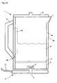
- FIG. 27 Another embodiment of the present invention is applicable to an immersed element vessel as shown in Figure 27 , in which an element 12 is immersed within the reservoir 5 rather than forming the base of the reservoir 5.
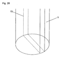
- the cordless connectors 3 and 4 are not 360° connectors, but require alignment between the vessel body 1 and the power base 2.
- a light source 70 is provided in the power base 2 and is arranged to illuminate a window 72 that extends down to the bottom of the vessel body 1, across its base, and up the other side, as shown schematically in Figure 28 . This allows the window 72 to be manufactured as a single piece providing a window on opposite sides of the vessel body 1.
- the light source 70 is arranged to provide light into an annular light guide in the vessel body 1, similar to that shown in Figure 10 , which then distributes illumination around the vessel body.
- a halogen lamp 80 is provided as a keep warm heater; hence, when the keep warm state is entered, the halogen lamp 80 is illuminated, thereby warming and illuminating the contents of the reservoir at the same time. This provides a visual indication that the keep warm state is operational.
- the element plate 12 is used as the main heater, but does not need a separate keep-warm track.
- another electrically powered combined heat and light source may be provided, such as a high-power LED array.
- heating is provided by a plurality of halogen lamps 74a, 74b, 74c positioned below a transparent plate 76 forming the bottom of the reservoir 76.
- the halogen lamps 74a, 74b and 74c are individually switchable so that the heating power may be varied; for example, one lamp may be switched on for the keep warm state, whilst all the lamps may be switched on for maximum heating power. As a result, the lighting state varies automatically as the heating state varies.
- the transparent plate 76 may include a plurality of different coloured filters corresponding to the different halogen lamps 74a, 74b, and 74c.
- each of the lamps 74a, 74b, and 74c may be controlled, for example by corresponding dimmers, so that the illumination brightness and colour may be more freely varied.
- the present invention is not limited to kettles and controls therefore; aspects of the invention may be applied to wasserkochers, coffee makers such as moka makers, Turkish tea makers, samovars, water boiling urns, pans, sauce makers, steamers, chocolate fountains, fondues, steamers, slow cookers and milk frothers, for example.
Landscapes
- Engineering & Computer Science (AREA)
- Physics & Mathematics (AREA)
- General Physics & Mathematics (AREA)
- Automation & Control Theory (AREA)
- Food Science & Technology (AREA)
- Cookers (AREA)
- Discharge Lamps And Accessories Thereof (AREA)
Claims (12)
- Behälter für die Erwärmung von Flüssigkeit umfassend einen Behälterkörper (1), eine kabellose Basis (2) für die Bereitstellung einer elektrischen Verbindung zum Behälterkörper (1) ungeachtet der Drehausrichtung des Behälterkörpers (1) auf der Basis (2), eine elektronische Steuerung (10) und einen Infrarot- oder optischen Verbinder für die Steuerung (10) zwischen dem Behälterkörper (1) und der Basis (2), wobei der Infrarot- oder optische Verbinder einen kreisförmigen oder ringförmigen Lichtleiter (2a) und einen Infrarot- oder optischen Koppler (1a) umfasst, die jeweils auf dem Behälterkörper (1) oder auf der Basis (2) angeordnet sind, sodass der Infrarot- oder optische Koppler (1a) eine Infrarot- oder optische Kopplung mit dem kreisförmigen oder ringförmigen Lichtleiter (2a) bereitstellt, wenn der Behälterkörper (1) auf der Basis (2) positioniert wird, ungeachtet der Drehausrichtung des Behälterkörpers (1) auf der Basis (2), wobei der Behälterkörper (1) eine Energieversorgung umfasst, die betreibbar ist, um Energie zumindest zu einem Teil der im Behälterkörper (1) bereitgestellten elektronischen Steuerung (10) zu liefern, wenn der Behälterkörper (1) von der Basis (2) entfernt ist.
- Behälter nach Anspruch 1, wobei der Infrarot- oder optische Verbinder angeordnet ist, um eine Lichtquelle (70) in der Basis (2) mit einem Beleuchtungsmittel im Behälterkörper (1) zu verbinden.
- Behälter nach Anspruch 1, wobei der optische Verbinder angeordnet ist, um eine optische Signalgabe zwischen dem Behälterkörper (1) und der Basis (2) zu verbinden.
- Behälter nach Anspruch 1 ferner umfassend eine vom Behälter getrennte oder trennbare Fernsteuerungsvorrichtung, wobei die Vorrichtung Folgendes umfasst:a. eine Benutzerschnittstelle (11) zum Empfangen einer Benutzereingabe;b. Erkennungsmittel zum Erkennen einer Bedingung im Zusammenhang mit dem Behälter;c. Schaltmittel zum Wechseln eines Heizzustands des Behälters; undd. Steuerungsmittel (10), das auf die Benutzereingabe und das Erkennungsmittel zum Steuern des Schaltmittels reagiert.
- Behälter nach Anspruch 4, wobei das Steuerungsmittel (10) zumindest teilweise in der Fernsteuerungsvorrichtung bereitgestellt ist.
- Behälter nach Anspruch 5, wobei die Fernsteuerungsvorrichtung durch den Benutzer programmiert werden kann.
- Behälter nach einem der Ansprüche 4 bis 6, wobei die Fernsteuerungsvorrichtung ferner ein Anzeigemittel zum Bereitstellen einer Angabe für den Benutzer umfasst, das auf das Steuerungsmittel reagiert.
- Behälter nach einem der Ansprüche 4 bis 7, wobei das Erkennungsmittel angeordnet ist, um einen Flüssigkeitspegel in dem Behälter zu erkennen.
- Behälter nach einem der Ansprüche 4 bis 8, wobei das Erkennungsmittel angeordnet ist, um einen Kochzustand der Flüssigkeit in dem Behälter zu erkennen.
- Behälter nach einem der Ansprüche 4 bis 9 umfassend eine bidirektionale Kommunikationsverknüpfung zwischen dem Behälter und der Fernsteuerungsvorrichtung.
- Behälter nach einem der Ansprüche 4 bis 10 ferner umfassend eine dazwischenliegende Vorrichtung, die angeordnet ist, um Kommunikation zwischen dem Behälter und der Fernsteuerungsvorrichtung bereitzustellen.
- Vorrichtung nach Anspruch 1, wobei die elektronische Steuerung (10) eine Benutzerschnittstelle (11) hat, die betreibbar ist, wenn der Behälterkörper (1) von der Basis (2) getrennt ist, um eine Einstellung auf der elektronischen Steuerung (10) zu ändern.
Priority Applications (1)
| Application Number | Priority Date | Filing Date | Title |
|---|---|---|---|
| EP13178601.4A EP2661994B1 (de) | 2007-06-18 | 2008-06-18 | Flüssigkeitserwärmungsbehälter und Steuerung |
Applications Claiming Priority (6)
| Application Number | Priority Date | Filing Date | Title |
|---|---|---|---|
| GBGB0711752.6A GB0711752D0 (en) | 2007-06-18 | 2007-06-18 | Electrical appliances |
| GBGB0714146.8A GB0714146D0 (en) | 2007-06-18 | 2007-07-19 | Electrical appliances |
| GB0721858A GB2448009A (en) | 2007-03-30 | 2007-11-07 | Liquid heating vessels |
| GBGB0808483.2A GB0808483D0 (en) | 2007-07-17 | 2008-05-09 | COntrols for liquid heating vessels |
| PCT/GB2008/001632 WO2008139173A2 (en) | 2007-05-11 | 2008-05-12 | Liquid heating vessels |
| PCT/GB2008/002073 WO2008155538A2 (en) | 2007-06-18 | 2008-06-18 | Liquid heating vessel and control |
Related Child Applications (2)
| Application Number | Title | Priority Date | Filing Date |
|---|---|---|---|
| EP13178601.4A Division EP2661994B1 (de) | 2007-06-18 | 2008-06-18 | Flüssigkeitserwärmungsbehälter und Steuerung |
| EP13178601.4A Division-Into EP2661994B1 (de) | 2007-06-18 | 2008-06-18 | Flüssigkeitserwärmungsbehälter und Steuerung |
Publications (2)
| Publication Number | Publication Date |
|---|---|
| EP2165243A1 EP2165243A1 (de) | 2010-03-24 |
| EP2165243B1 true EP2165243B1 (de) | 2014-02-12 |
Family
ID=38332294
Family Applications (2)
| Application Number | Title | Priority Date | Filing Date |
|---|---|---|---|
| EP08762397.1A Not-in-force EP2165243B1 (de) | 2007-06-18 | 2008-06-18 | Flüssigkeitserwärmungsbehälter und steuerung |
| EP13178601.4A Active EP2661994B1 (de) | 2007-06-18 | 2008-06-18 | Flüssigkeitserwärmungsbehälter und Steuerung |
Family Applications After (1)
| Application Number | Title | Priority Date | Filing Date |
|---|---|---|---|
| EP13178601.4A Active EP2661994B1 (de) | 2007-06-18 | 2008-06-18 | Flüssigkeitserwärmungsbehälter und Steuerung |
Country Status (4)
| Country | Link |
|---|---|
| EP (2) | EP2165243B1 (de) |
| CN (3) | CN102160013B (de) |
| GB (2) | GB0711752D0 (de) |
| WO (1) | WO2008155538A2 (de) |
Cited By (7)
| Publication number | Priority date | Publication date | Assignee | Title |
|---|---|---|---|---|
| DE102019119720A1 (de) * | 2019-07-22 | 2021-01-28 | Miele & Cie. Kg | Gargeschirr zum Garen wenigstens eines Garguts |
| DE102019219609B3 (de) * | 2019-12-13 | 2021-04-01 | BSH Hausgeräte GmbH | Verfahren zur Kalibrierung einer Temperaturerfassungseinrichtung in einem Getränkeautomaten |
| US11366075B2 (en) | 2017-04-28 | 2022-06-21 | Electrolux Appliances Aktiebolag | Method for determining an amount of deposition of scale on a heating element and household appliance comprising a heating element |
| DE102021123647A1 (de) | 2021-09-13 | 2023-03-16 | Simon Best | Elektrischer Wassererhitzer zum Erwärmen und Garen von Nahrungsmitteln |
| EP4224676A1 (de) * | 2010-11-02 | 2023-08-09 | Ember Technologies, Inc. | Beheiztes oder gekühltes trinkgeschirr |
| US12035843B2 (en) | 2010-11-02 | 2024-07-16 | Ember Technologies, Inc. | Dishware or serverware with active temperature control |
| WO2025184707A1 (en) * | 2024-03-07 | 2025-09-12 | Breville Pty Limited | A jug and method of guiding a user to froth milk |
Families Citing this family (104)
| Publication number | Priority date | Publication date | Assignee | Title |
|---|---|---|---|---|
| US20110008029A1 (en) * | 2008-01-29 | 2011-01-13 | Von Seidel Michael | Culinary electric hot water appliance with automatic switch |
| GB2466219A (en) * | 2008-12-12 | 2010-06-16 | Otter Controls Ltd | Thick film heating element |
| GB0902726D0 (en) | 2009-02-18 | 2009-04-01 | Otter Controls Ltd | Liquid heating appliances |
| DE102009002841A1 (de) * | 2009-05-06 | 2010-11-18 | Emsa Gmbh | Verfahren zur berührungslosen Füllstandsmessung bei Getränkebehältern und Getränkebehälter mit einer Füllstandsanzeige |
| TR200904257A2 (tr) | 2009-06-01 | 2010-12-21 | Yenel Yeni̇li̇kçi̇ Ve Buluşçu Elekt.Si̇stemler Sanayi̇ Ve Ti̇caret Li̇mi̇ted Şi̇rketi̇ | Bir türk kahvesi makinesi ve türk kahvesi pişirme yöntemi |
| ITMI20090986A1 (it) * | 2009-06-05 | 2010-12-06 | San Marco Di Francesco Bugatti & C S A P A | Bollitore per liquidi, particolarmente per uso domestico, con elementi di controllo delle funzioni eseguibili. |
| JP5809161B2 (ja) * | 2009-12-02 | 2015-11-10 | ネステク ソシエテ アノニム | 遠隔サービス機能をサポートする飲料調製マシン |
| TWI391114B (zh) * | 2009-12-18 | 2013-04-01 | Univ Nat Formosa | Light - emitting diode food heaters |
| DE102010008270A1 (de) * | 2010-02-17 | 2010-08-05 | SEVERIN ELEKTROGERÄTE GmbH | Elektrische Maschine |
| GB2477944B (en) | 2010-02-18 | 2015-04-01 | Otter Controls Ltd | Cordless electrical appliances |
| US8518501B2 (en) | 2010-03-10 | 2013-08-27 | Restaurant Technology, Inc. | Food holding device, method of making, and method of storing cooked food |
| JP5885740B2 (ja) * | 2010-06-17 | 2016-03-15 | ネステク ソシエテ アノニム | 例えばコーヒーマシンのための温度調整装置の高速加熱 |
| CN101912228A (zh) * | 2010-07-09 | 2010-12-15 | 美的集团有限公司 | 一种电热水壶 |
| WO2012039772A1 (en) | 2010-09-21 | 2012-03-29 | Joseph Behm | System for precise temperature control of liquids in consumer products |
| US9814331B2 (en) | 2010-11-02 | 2017-11-14 | Ember Technologies, Inc. | Heated or cooled dishware and drinkware |
| US11950726B2 (en) | 2010-11-02 | 2024-04-09 | Ember Technologies, Inc. | Drinkware container with active temperature control |
| US8759721B1 (en) * | 2010-11-02 | 2014-06-24 | Piatto Technologies, Inc. | Heated or cooled dishwasher safe dishware and drinkware |
| US9035222B2 (en) * | 2010-11-02 | 2015-05-19 | Oromo Technologies, Inc. | Heated or cooled dishware and drinkware |
| GB2497978A (en) | 2011-12-23 | 2013-07-03 | Otter Controls Ltd | Liquid heating vessel and control |
| EP2846665A4 (de) * | 2012-05-06 | 2016-01-27 | Bruce D Burrows | Kaffeeaufbrühvorrichtung vorrichtungen und verfahren zum brauen von getränken |
| GB2498823B (en) * | 2012-07-03 | 2013-12-11 | Robert Hill | A water heater |
| CN103697594A (zh) * | 2012-09-27 | 2014-04-02 | 芜湖美的厨卫电器制造有限公司 | 电热水器及其控制系统与控制方法 |
| WO2014085598A1 (en) * | 2012-11-30 | 2014-06-05 | Elwha Llc | Systems and methods for producing hydrogen gas |
| US9434612B2 (en) | 2012-11-30 | 2016-09-06 | Elwha, Llc | Systems and methods for producing hydrogen gas |
| US9156688B2 (en) | 2012-11-30 | 2015-10-13 | Elwha Llc | Systems and methods for producing hydrogen gas |
| AU2014242042B2 (en) * | 2013-03-14 | 2018-11-29 | Ember Technologies, Inc. | Heated or cooled dishware and drinkware |
| JP6663850B2 (ja) | 2013-09-13 | 2020-03-13 | フィッシャー アンド ペイケル ヘルスケア リミテッド | 加湿システムの接続 |
| US20160235243A1 (en) * | 2013-09-30 | 2016-08-18 | Breville Pty Limited | Apparatus and Method for Frothing Milk |
| GB2525836B (en) | 2013-11-25 | 2017-09-20 | Kenwood Ltd | Electro chromatic vessels for processing and storage for foodstuffs |
| CN103637698B (zh) * | 2013-11-29 | 2016-06-01 | 美的集团股份有限公司 | 液体的电加热容器 |
| WO2015084294A1 (en) * | 2013-12-02 | 2015-06-11 | Richards Corporation | Aircraft kettle temperature control system |
| CN103759408A (zh) * | 2014-01-13 | 2014-04-30 | 法罗力热能设备(中国)有限公司 | 带有水垢检测、报警和自动清洗功能的电热水器 |
| EP3116352A4 (de) * | 2014-03-14 | 2018-01-17 | Spectrum Brands, Inc. | Getränkegerät zur verwendung mit einer fernkommunikationsvorrichtung |
| CN203914526U (zh) * | 2014-06-09 | 2014-11-05 | 朱星曈 | 一种可监测水位的电水壶 |
| US9782036B2 (en) | 2015-02-24 | 2017-10-10 | Ember Technologies, Inc. | Heated or cooled portable drinkware |
| WO2016156096A1 (en) * | 2015-04-03 | 2016-10-06 | Arcelik Anonim Sirketi | A hot beverage preparation machine with decreased stand-by energy consumption |
| US10136751B2 (en) | 2015-06-25 | 2018-11-27 | La San Marco Di Francesco Bugatti & C.—S.A.P.A. | Electric kettle |
| AU2016290887B2 (en) | 2015-07-08 | 2021-06-10 | Breville Pty Limited | Kitchen appliance for sensing food and beverage properties |
| CN106691174A (zh) * | 2015-08-11 | 2017-05-24 | 广东海利集团有限公司 | 超声波水位检测煮水壶 |
| CN105167595A (zh) * | 2015-08-28 | 2015-12-23 | 中山市亚美斯电子科技有限公司 | 电热开水瓶的安全结构 |
| CN105167598A (zh) * | 2015-10-08 | 2015-12-23 | 格力电器(中山)小家电制造有限公司 | 电热壶及其底座组件 |
| CN106937824B (zh) * | 2016-01-04 | 2019-03-12 | 广东美的生活电器制造有限公司 | 电热水壶 |
| WO2017151362A1 (en) | 2016-02-29 | 2017-09-08 | Ember Technologies, Inc. | Liquid container and module for adjusting temperature of liquid in container |
| US10105006B2 (en) * | 2016-04-07 | 2018-10-23 | Electrolux Home Products, Inc. | Cooking appliance with indicators formed using electrochromic material |
| WO2017192396A1 (en) | 2016-05-02 | 2017-11-09 | Ember Technologies, Inc. | Heated or cooled drinkware |
| JP6522153B2 (ja) | 2016-05-12 | 2019-05-29 | エンバー テクノロジーズ, インコーポレイテッド | 飲料用容器及び食器並びに飲料用容器及び食器のためのアクティブ制御モジュール |
| CN107773038B (zh) * | 2016-08-31 | 2021-04-09 | 广东美的生活电器制造有限公司 | 液体加热容器的除氯方法及装置、液体加热容器 |
| KR20180035662A (ko) | 2016-09-29 | 2018-04-06 | 엠버 테크놀로지스 인코포레이티드 | 가열되거나 냉각된 음료용기 |
| CN107874586A (zh) * | 2016-09-30 | 2018-04-06 | 广东美的生活电器制造有限公司 | 液体加热容器及其加热控制方法 |
| DE102016219590A1 (de) * | 2016-10-10 | 2018-04-12 | E.G.O. Elektro-Gerätebau GmbH | Verfahren zum Betrieb eines Induktionskochfelds und Induktionskochfeld |
| US9995529B1 (en) | 2016-12-08 | 2018-06-12 | Nova Laboratories | Temperature-regulating containment system |
| GB2560176A (en) * | 2017-03-01 | 2018-09-05 | Kenwood Ltd | Beverage making appliance |
| CN108692808B (zh) * | 2017-04-10 | 2021-10-29 | 深圳市元疆科技有限公司 | 一种测振式识别锅内液体状态的方法和装置 |
| EP3446600B1 (de) * | 2017-08-24 | 2020-08-12 | Eksen Makine Sanayi ve Ticaret A.S. | Verfahren und vorrichtung zur getränkezubereitung |
| WO2019051529A1 (en) | 2017-09-12 | 2019-03-21 | Breville Pty Limited | LIQUID HEATING APPARATUS FOR MAKING A BEVERAGE AND ASSOCIATED METHOD, POWER MANAGEMENT SYSTEM, AND MICROCONTROLLER READABLE MEDIUM |
| CN116256388B (zh) * | 2017-11-28 | 2025-12-19 | 广研德孚科技发展(深圳)有限公司 | 一种发动机防冻液和刹车油的沸点测试方法 |
| CN107843917A (zh) * | 2017-12-04 | 2018-03-27 | 美钻石油钻采系统(上海)有限公司 | 一种水下装备抗震装置 |
| CN107912978A (zh) * | 2017-12-28 | 2018-04-17 | 佛山市顺德区米创智能科技有限公司 | 一种智能电磁加热水壶 |
| DE102017223896A1 (de) * | 2017-12-29 | 2019-07-04 | BSH Hausgeräte GmbH | Wasserkocheinrichtung mit einer am Griff angeordneten Wiegeeinrichtung |
| CN109984614B (zh) * | 2017-12-29 | 2024-04-12 | 福州品行科技发展有限公司 | 一种可分离式超声波除垢冲泡加热装置 |
| EP3745930B1 (de) | 2018-01-31 | 2021-12-29 | Ember Technologies, Inc. | Aktiv beheiztes oder gekühltes säuglingsflaschensystem |
| CN108415482B (zh) * | 2018-01-31 | 2020-06-16 | 厦门芯阳科技股份有限公司 | 一种基于咖啡机控温自学习算法的控温方法、系统及装置 |
| EP3527114B1 (de) * | 2018-02-20 | 2021-11-17 | Purtek Machine Industry And Trade Inc. | Getränkezubereitungsvorrichtung mit einem niveau- und kochsensorelement |
| US10969141B2 (en) | 2018-03-13 | 2021-04-06 | Ngb Innovations Llc | Regulating temperature and reducing buildup in a water heating system |
| EP3781884A1 (de) | 2018-04-19 | 2021-02-24 | Ember Technologies, Inc. | Tragbarer kühler mit aktiver temperaturregelung |
| CN108401309A (zh) * | 2018-05-10 | 2018-08-14 | 东莞市可乐狗电子科技有限公司 | 一种多电压适用厚膜发热盘 |
| CN108680962A (zh) * | 2018-06-04 | 2018-10-19 | 广州市德弘五金制品有限公司 | 一种电陶炉激光检测系统 |
| CN108803687A (zh) * | 2018-07-25 | 2018-11-13 | 珠海格力电器股份有限公司 | 用于电器缺液保护的控制装置及其方法与电器 |
| KR102676479B1 (ko) * | 2018-11-30 | 2024-06-18 | 엘지전자 주식회사 | 릴레이 설치 위치가 개선된 전기 포트 |
| KR102683312B1 (ko) * | 2018-12-14 | 2024-07-08 | 엘지전자 주식회사 | 보온 작업 유지 기능이 개선된 전기 포트 |
| CN109674345A (zh) * | 2018-12-20 | 2019-04-26 | 深圳市优点智联科技有限公司 | 即热式热水的加热水温调整方法、装置、存储介质及系统 |
| CN109658936B (zh) * | 2019-01-03 | 2023-04-21 | 陕西手一网络科技有限公司 | 一种提高烧水壶语音识别率的方法 |
| CN118640630A (zh) | 2019-01-11 | 2024-09-13 | 恩伯技术公司 | 具有主动温度控制的便携式冷却器 |
| KR102716260B1 (ko) | 2019-03-21 | 2024-10-11 | 엘지전자 주식회사 | 전기 주전자 |
| US12256861B2 (en) | 2019-01-25 | 2025-03-25 | Lg Electronics Inc. | Electric kettle |
| KR102716254B1 (ko) | 2019-03-21 | 2024-10-11 | 엘지전자 주식회사 | 전기 주전자 |
| KR102716268B1 (ko) | 2019-03-21 | 2024-10-11 | 엘지전자 주식회사 | 전기 주전자 |
| KR102716256B1 (ko) | 2019-03-21 | 2024-10-11 | 엘지전자 주식회사 | 전기 주전자 |
| KR102716261B1 (ko) | 2019-03-21 | 2024-10-11 | 엘지전자 주식회사 | 전기 주전자 |
| KR102767254B1 (ko) | 2019-03-21 | 2025-02-14 | 엘지전자 주식회사 | 전기 주전자 |
| KR102716262B1 (ko) | 2019-03-21 | 2024-10-11 | 엘지전자 주식회사 | 전기 주전자 |
| KR102716264B1 (ko) | 2019-03-21 | 2024-10-11 | 엘지전자 주식회사 | 전기 주전자 |
| EP3945962B1 (de) * | 2019-03-26 | 2025-07-02 | De' Longhi Appliances S.r.l. Con Unico Socio | Maschine und verfahren zur zubereitung von getränken |
| CA3143365A1 (en) | 2019-06-25 | 2020-12-30 | Ember Technologies, Inc. | Portable cooler |
| US11162716B2 (en) | 2019-06-25 | 2021-11-02 | Ember Technologies, Inc. | Portable cooler |
| US11668508B2 (en) | 2019-06-25 | 2023-06-06 | Ember Technologies, Inc. | Portable cooler |
| CN110530255B (zh) * | 2019-09-04 | 2021-06-11 | 中国电建集团中南勘测设计研究院有限公司 | 一种地应力测试用橡皮叉式三轴应变计线缆连接装置、三轴应变计及其使用方法 |
| CN110731700B (zh) * | 2019-09-24 | 2021-11-12 | 成都越凡创新科技有限公司 | 移动胶囊咖啡机供水系统及其控制方法 |
| US11504684B2 (en) * | 2019-09-30 | 2022-11-22 | Ohaus Corporation | Hotplate stirrer |
| RU2741285C1 (ru) * | 2019-10-14 | 2021-01-25 | Общество с ограниченной ответственностью "ЭР ЛАБ" | Устройство для нагрева жидкости с беспроводным управлением, подсветкой, индикацией и функцией определения количества жидкости |
| JP7678592B2 (ja) * | 2019-11-06 | 2025-05-16 | ポワ コーポレイション プロプライエトリー リミテッド | ケトル |
| CN111436878B (zh) * | 2020-03-31 | 2023-07-25 | 宁波方太厨具有限公司 | 一种清洗机及清洗方法 |
| CA3178289A1 (en) | 2020-04-03 | 2021-10-07 | Clayton Alexander | Portable cooler with active temperature control |
| CN112244631B (zh) * | 2020-10-19 | 2022-06-14 | 珠海格力电器股份有限公司 | 一种电热水壶 |
| CN113385246B (zh) * | 2021-02-04 | 2022-07-19 | 唐飞鹏 | 一种共沸恒温加热装置 |
| WO2022186805A1 (en) * | 2021-03-02 | 2022-09-09 | Technocast Otomotiv Sanayi Ve Ticaret Anonim Sirketi | A turkish cofee maker having a cofee pot with a sensor |
| CN113068982A (zh) * | 2021-03-29 | 2021-07-06 | 深圳市鑫同创电子有限公司 | 基于倾斜角度检测水杯干烧的方法及电路 |
| CN115815215A (zh) * | 2022-11-08 | 2023-03-21 | 乳源东阳光智能科技有限公司 | 一种加热组件及其坐便器和加热组件清洗方法 |
| CN116182937A (zh) * | 2022-12-14 | 2023-05-30 | 中国科学院空间应用工程与技术中心 | 一种用于研究空间池沸腾现象的实验装置 |
| EP4694736A1 (de) * | 2023-04-13 | 2026-02-18 | Strix Limited | Flüssigkeitserhitzungsvorrichtung mit bypass-stromversorgungsschaltung |
| EP4591764A1 (de) * | 2023-12-06 | 2025-07-30 | Bellnix Co., Ltd. | Verfahren und vorrichtung zur schätzung der temperatur des inhalts in einem elektrischen topf |
| US12369741B1 (en) | 2024-01-18 | 2025-07-29 | Sharkninja Operating Llc | Preventing coffee bean grinder jamming |
| WO2025155326A1 (en) | 2024-01-18 | 2025-07-24 | Sharkninja Operating Llc | Preparation of beverage machines for cold beverage brewing |
| CN120122765A (zh) * | 2025-05-13 | 2025-06-10 | 绍兴市中等专业学校 | 用于羊肚菌工厂化种植的智能温湿度控制系统 |
Citations (5)
| Publication number | Priority date | Publication date | Assignee | Title |
|---|---|---|---|---|
| EP0061334A1 (de) * | 1981-03-23 | 1982-09-29 | The Babcock & Wilcox Company | Flüssigkeitsstand-Messeinheit für die Fernanzeige und lokale Anzeige des Flüssigkeitsstandes |
| GB2328143A (en) * | 1997-08-16 | 1999-02-17 | Kenwood Marks Ltd | A domestic electrical appliance removable from a base |
| EP1195120A1 (de) * | 2000-10-04 | 2002-04-10 | Seb S.A. | Elektrisches Haushaltsgerät mit einem bewegbaren Element, das auf einem Sockel aufgesetzt werden kann |
| EP1816659A1 (de) * | 2006-02-02 | 2007-08-08 | Efbe Elektrogeräte GmbH | Elektrisches Haushaltsgerätesystem |
| WO2008144805A1 (en) * | 2007-05-25 | 2008-12-04 | Breville Pty Limited | Data communication with cordless base |
Family Cites Families (10)
| Publication number | Priority date | Publication date | Assignee | Title |
|---|---|---|---|---|
| JPH0817742B2 (ja) * | 1990-12-19 | 1996-02-28 | 象印マホービン株式会社 | 電気ポットの沸騰制御方法 |
| JP3683435B2 (ja) * | 1999-04-20 | 2005-08-17 | ホシザキ電機株式会社 | 貯湯装置 |
| DE60035954T2 (de) * | 1999-10-11 | 2008-01-24 | Strix Ltd. | Schnurlose elektrische geräte |
| US6791467B1 (en) * | 2000-03-23 | 2004-09-14 | Flextronics Semiconductor, Inc. | Adaptive remote controller |
| WO2005059670A1 (en) * | 2003-12-16 | 2005-06-30 | Otter Controls Limited | Improvements relating to thermal controls |
| JP2007529708A (ja) * | 2004-03-15 | 2007-10-25 | ジップ インダストリーズ (オーストラリア) プロプライアタリー リミテッド | 温水器及びその運転方法 |
| CN2730265Y (zh) * | 2004-06-14 | 2005-10-05 | 周传伟 | 一种电热水壶 |
| DE102005006720A1 (de) * | 2005-02-04 | 2006-08-10 | Eldora Gmbh | Gerät zum Erhitzen einer Flüssigkeit, insbesondere Wasserkocher |
| CN100370376C (zh) * | 2005-09-08 | 2008-02-20 | 晶辉科技(深圳)有限公司 | 电热水壶水沸腾的判断方法 |
| CN201069266Y (zh) * | 2007-05-15 | 2008-06-04 | 刘瑜琦 | 电子式电茶壶温度传输控制装置 |
-
2007
- 2007-06-18 GB GBGB0711752.6A patent/GB0711752D0/en not_active Ceased
- 2007-07-19 GB GBGB0714146.8A patent/GB0714146D0/en not_active Ceased
-
2008
- 2008-06-18 EP EP08762397.1A patent/EP2165243B1/de not_active Not-in-force
- 2008-06-18 CN CN200880103162.0A patent/CN102160013B/zh not_active Expired - Fee Related
- 2008-06-18 CN CN2011104440929A patent/CN102563842A/zh active Pending
- 2008-06-18 CN CNU2008201335110U patent/CN201348377Y/zh not_active Expired - Fee Related
- 2008-06-18 EP EP13178601.4A patent/EP2661994B1/de active Active
- 2008-06-18 WO PCT/GB2008/002073 patent/WO2008155538A2/en not_active Ceased
Patent Citations (5)
| Publication number | Priority date | Publication date | Assignee | Title |
|---|---|---|---|---|
| EP0061334A1 (de) * | 1981-03-23 | 1982-09-29 | The Babcock & Wilcox Company | Flüssigkeitsstand-Messeinheit für die Fernanzeige und lokale Anzeige des Flüssigkeitsstandes |
| GB2328143A (en) * | 1997-08-16 | 1999-02-17 | Kenwood Marks Ltd | A domestic electrical appliance removable from a base |
| EP1195120A1 (de) * | 2000-10-04 | 2002-04-10 | Seb S.A. | Elektrisches Haushaltsgerät mit einem bewegbaren Element, das auf einem Sockel aufgesetzt werden kann |
| EP1816659A1 (de) * | 2006-02-02 | 2007-08-08 | Efbe Elektrogeräte GmbH | Elektrisches Haushaltsgerätesystem |
| WO2008144805A1 (en) * | 2007-05-25 | 2008-12-04 | Breville Pty Limited | Data communication with cordless base |
Cited By (7)
| Publication number | Priority date | Publication date | Assignee | Title |
|---|---|---|---|---|
| EP4224676A1 (de) * | 2010-11-02 | 2023-08-09 | Ember Technologies, Inc. | Beheiztes oder gekühltes trinkgeschirr |
| US12035843B2 (en) | 2010-11-02 | 2024-07-16 | Ember Technologies, Inc. | Dishware or serverware with active temperature control |
| US11366075B2 (en) | 2017-04-28 | 2022-06-21 | Electrolux Appliances Aktiebolag | Method for determining an amount of deposition of scale on a heating element and household appliance comprising a heating element |
| DE102019119720A1 (de) * | 2019-07-22 | 2021-01-28 | Miele & Cie. Kg | Gargeschirr zum Garen wenigstens eines Garguts |
| DE102019219609B3 (de) * | 2019-12-13 | 2021-04-01 | BSH Hausgeräte GmbH | Verfahren zur Kalibrierung einer Temperaturerfassungseinrichtung in einem Getränkeautomaten |
| DE102021123647A1 (de) | 2021-09-13 | 2023-03-16 | Simon Best | Elektrischer Wassererhitzer zum Erwärmen und Garen von Nahrungsmitteln |
| WO2025184707A1 (en) * | 2024-03-07 | 2025-09-12 | Breville Pty Limited | A jug and method of guiding a user to froth milk |
Also Published As
| Publication number | Publication date |
|---|---|
| EP2165243A1 (de) | 2010-03-24 |
| CN201348377Y (zh) | 2009-11-18 |
| GB0714146D0 (en) | 2007-08-29 |
| GB0711752D0 (en) | 2007-07-25 |
| EP2661994B1 (de) | 2016-09-14 |
| CN102160013A (zh) | 2011-08-17 |
| WO2008155538A2 (en) | 2008-12-24 |
| CN102160013B (zh) | 2014-03-26 |
| EP2661994A1 (de) | 2013-11-13 |
| CN102563842A (zh) | 2012-07-11 |
Similar Documents
| Publication | Publication Date | Title |
|---|---|---|
| EP2165243B1 (de) | Flüssigkeitserwärmungsbehälter und steuerung | |
| CN103792973B (zh) | 液体加热容器及其控制器 | |
| US8208801B2 (en) | Multi-function liquid container | |
| CN102187292A (zh) | 液体加热容器和控制装置 | |
| CN102762135B (zh) | 加热的液体用的容器和电器装置 | |
| WO2007131271A1 (en) | Improved temperature sensor for an electric heating vessel | |
| WO2011002421A2 (en) | A turkish coffee machine and a turkish coffee brewing method | |
| JP5143090B2 (ja) | 誘導加熱調理器 | |
| KR20200141781A (ko) | 내용물의 온도 유지를 위한 전기레인지의 화구제어방법 | |
| AU2007314163B2 (en) | Electric heating appliance with data display | |
| JP2009266468A (ja) | 誘導加熱調理器 | |
| KR102838130B1 (ko) | 파우셋부가 구비된 전기레인지를 이용한 자동조리 제어방법 | |
| AU2010292990B2 (en) | Electric kettle | |
| KR200280718Y1 (ko) | 머그컵 | |
| JP3546811B2 (ja) | 調理家電機器の予約時刻設定システム | |
| AU2010200571B2 (en) | Improved temperature sensor for an electric heating appliance | |
| AU2013200269B2 (en) | Improved temperature sensor for an electric heating vessel | |
| GB2629134A (en) | Liquid heating appliance | |
| JP2011009031A (ja) | 誘導加熱調理器 | |
| WO2017194077A1 (en) | A cooking control device | |
| AU2015264889A1 (en) | Improved temperature sensor for an electric heating vessel |
Legal Events
| Date | Code | Title | Description |
|---|---|---|---|
| PUAI | Public reference made under article 153(3) epc to a published international application that has entered the european phase |
Free format text: ORIGINAL CODE: 0009012 |
|
| 17P | Request for examination filed |
Effective date: 20100118 |
|
| AK | Designated contracting states |
Kind code of ref document: A1 Designated state(s): AT BE BG CH CY CZ DE DK EE ES FI FR GB GR HR HU IE IS IT LI LT LU LV MC MT NL NO PL PT RO SE SI SK TR |
|
| AX | Request for extension of the european patent |
Extension state: AL BA MK RS |
|
| RIN1 | Information on inventor provided before grant (corrected) |
Inventor name: SIDDONS, JEREMY Inventor name: GAETA, ANTONIO, MARTIN Inventor name: WRIGHT, PETER, HALLAM Inventor name: HADFIELD, ROBERT, HENRY Inventor name: MOORE, ROBIN, KEITH Inventor name: SMITH, DAVID, ANDREW |
|
| DAX | Request for extension of the european patent (deleted) | ||
| 17Q | First examination report despatched |
Effective date: 20110721 |
|
| GRAP | Despatch of communication of intention to grant a patent |
Free format text: ORIGINAL CODE: EPIDOSNIGR1 |
|
| INTG | Intention to grant announced |
Effective date: 20130822 |
|
| RAP1 | Party data changed (applicant data changed or rights of an application transferred) |
Owner name: OTTER CONTROLS LIMITED |
|
| RIN1 | Information on inventor provided before grant (corrected) |
Inventor name: SIDDONS, JEREMY Inventor name: SMITH, DAVID, ANDREW Inventor name: WRIGHT, PETER, HALLAM Inventor name: HADFIELD, ROBERT, HENRY Inventor name: GAETA, ANTONIO, MARTIN Inventor name: MOORE, ROBIN, KEITH |
|
| GRAS | Grant fee paid |
Free format text: ORIGINAL CODE: EPIDOSNIGR3 |
|
| GRAA | (expected) grant |
Free format text: ORIGINAL CODE: 0009210 |
|
| AK | Designated contracting states |
Kind code of ref document: B1 Designated state(s): AT BE BG CH CY CZ DE DK EE ES FI FR GB GR HR HU IE IS IT LI LT LU LV MC MT NL NO PL PT RO SE SI SK TR |
|
| REG | Reference to a national code |
Ref country code: GB Ref legal event code: FG4D |
|
| REG | Reference to a national code |
Ref country code: CH Ref legal event code: EP |
|
| REG | Reference to a national code |
Ref country code: AT Ref legal event code: REF Ref document number: 652401 Country of ref document: AT Kind code of ref document: T Effective date: 20140215 |
|
| REG | Reference to a national code |
Ref country code: IE Ref legal event code: FG4D |
|
| REG | Reference to a national code |
Ref country code: DE Ref legal event code: R096 Ref document number: 602008030257 Country of ref document: DE Effective date: 20140327 |
|
| REG | Reference to a national code |
Ref country code: NL Ref legal event code: VDEP Effective date: 20140212 |
|
| REG | Reference to a national code |
Ref country code: AT Ref legal event code: MK05 Ref document number: 652401 Country of ref document: AT Kind code of ref document: T Effective date: 20140212 |
|
| REG | Reference to a national code |
Ref country code: LT Ref legal event code: MG4D |
|
| PG25 | Lapsed in a contracting state [announced via postgrant information from national office to epo] |
Ref country code: LT Free format text: LAPSE BECAUSE OF FAILURE TO SUBMIT A TRANSLATION OF THE DESCRIPTION OR TO PAY THE FEE WITHIN THE PRESCRIBED TIME-LIMIT Effective date: 20140212 Ref country code: IS Free format text: LAPSE BECAUSE OF FAILURE TO SUBMIT A TRANSLATION OF THE DESCRIPTION OR TO PAY THE FEE WITHIN THE PRESCRIBED TIME-LIMIT Effective date: 20140612 Ref country code: NO Free format text: LAPSE BECAUSE OF FAILURE TO SUBMIT A TRANSLATION OF THE DESCRIPTION OR TO PAY THE FEE WITHIN THE PRESCRIBED TIME-LIMIT Effective date: 20140512 |
|
| PG25 | Lapsed in a contracting state [announced via postgrant information from national office to epo] |
Ref country code: ES Free format text: LAPSE BECAUSE OF FAILURE TO SUBMIT A TRANSLATION OF THE DESCRIPTION OR TO PAY THE FEE WITHIN THE PRESCRIBED TIME-LIMIT Effective date: 20140212 Ref country code: AT Free format text: LAPSE BECAUSE OF FAILURE TO SUBMIT A TRANSLATION OF THE DESCRIPTION OR TO PAY THE FEE WITHIN THE PRESCRIBED TIME-LIMIT Effective date: 20140212 Ref country code: FI Free format text: LAPSE BECAUSE OF FAILURE TO SUBMIT A TRANSLATION OF THE DESCRIPTION OR TO PAY THE FEE WITHIN THE PRESCRIBED TIME-LIMIT Effective date: 20140212 Ref country code: NL Free format text: LAPSE BECAUSE OF FAILURE TO SUBMIT A TRANSLATION OF THE DESCRIPTION OR TO PAY THE FEE WITHIN THE PRESCRIBED TIME-LIMIT Effective date: 20140212 Ref country code: PT Free format text: LAPSE BECAUSE OF FAILURE TO SUBMIT A TRANSLATION OF THE DESCRIPTION OR TO PAY THE FEE WITHIN THE PRESCRIBED TIME-LIMIT Effective date: 20140612 Ref country code: CY Free format text: LAPSE BECAUSE OF FAILURE TO SUBMIT A TRANSLATION OF THE DESCRIPTION OR TO PAY THE FEE WITHIN THE PRESCRIBED TIME-LIMIT Effective date: 20140212 Ref country code: SE Free format text: LAPSE BECAUSE OF FAILURE TO SUBMIT A TRANSLATION OF THE DESCRIPTION OR TO PAY THE FEE WITHIN THE PRESCRIBED TIME-LIMIT Effective date: 20140212 |
|
| PG25 | Lapsed in a contracting state [announced via postgrant information from national office to epo] |
Ref country code: HR Free format text: LAPSE BECAUSE OF FAILURE TO SUBMIT A TRANSLATION OF THE DESCRIPTION OR TO PAY THE FEE WITHIN THE PRESCRIBED TIME-LIMIT Effective date: 20140212 Ref country code: LV Free format text: LAPSE BECAUSE OF FAILURE TO SUBMIT A TRANSLATION OF THE DESCRIPTION OR TO PAY THE FEE WITHIN THE PRESCRIBED TIME-LIMIT Effective date: 20140212 Ref country code: BE Free format text: LAPSE BECAUSE OF FAILURE TO SUBMIT A TRANSLATION OF THE DESCRIPTION OR TO PAY THE FEE WITHIN THE PRESCRIBED TIME-LIMIT Effective date: 20140212 |
|
| PG25 | Lapsed in a contracting state [announced via postgrant information from national office to epo] |
Ref country code: EE Free format text: LAPSE BECAUSE OF FAILURE TO SUBMIT A TRANSLATION OF THE DESCRIPTION OR TO PAY THE FEE WITHIN THE PRESCRIBED TIME-LIMIT Effective date: 20140212 Ref country code: DK Free format text: LAPSE BECAUSE OF FAILURE TO SUBMIT A TRANSLATION OF THE DESCRIPTION OR TO PAY THE FEE WITHIN THE PRESCRIBED TIME-LIMIT Effective date: 20140212 Ref country code: RO Free format text: LAPSE BECAUSE OF FAILURE TO SUBMIT A TRANSLATION OF THE DESCRIPTION OR TO PAY THE FEE WITHIN THE PRESCRIBED TIME-LIMIT Effective date: 20140212 Ref country code: CZ Free format text: LAPSE BECAUSE OF FAILURE TO SUBMIT A TRANSLATION OF THE DESCRIPTION OR TO PAY THE FEE WITHIN THE PRESCRIBED TIME-LIMIT Effective date: 20140212 |
|
| REG | Reference to a national code |
Ref country code: DE Ref legal event code: R097 Ref document number: 602008030257 Country of ref document: DE |
|
| PG25 | Lapsed in a contracting state [announced via postgrant information from national office to epo] |
Ref country code: SK Free format text: LAPSE BECAUSE OF FAILURE TO SUBMIT A TRANSLATION OF THE DESCRIPTION OR TO PAY THE FEE WITHIN THE PRESCRIBED TIME-LIMIT Effective date: 20140212 Ref country code: PL Free format text: LAPSE BECAUSE OF FAILURE TO SUBMIT A TRANSLATION OF THE DESCRIPTION OR TO PAY THE FEE WITHIN THE PRESCRIBED TIME-LIMIT Effective date: 20140212 |
|
| PLBE | No opposition filed within time limit |
Free format text: ORIGINAL CODE: 0009261 |
|
| STAA | Information on the status of an ep patent application or granted ep patent |
Free format text: STATUS: NO OPPOSITION FILED WITHIN TIME LIMIT |
|
| 26N | No opposition filed |
Effective date: 20141113 |
|
| PG25 | Lapsed in a contracting state [announced via postgrant information from national office to epo] |
Ref country code: LU Free format text: LAPSE BECAUSE OF FAILURE TO SUBMIT A TRANSLATION OF THE DESCRIPTION OR TO PAY THE FEE WITHIN THE PRESCRIBED TIME-LIMIT Effective date: 20140618 Ref country code: MC Free format text: LAPSE BECAUSE OF FAILURE TO SUBMIT A TRANSLATION OF THE DESCRIPTION OR TO PAY THE FEE WITHIN THE PRESCRIBED TIME-LIMIT Effective date: 20140212 |
|
| REG | Reference to a national code |
Ref country code: CH Ref legal event code: PL |
|
| REG | Reference to a national code |
Ref country code: DE Ref legal event code: R097 Ref document number: 602008030257 Country of ref document: DE Effective date: 20141113 |
|
| REG | Reference to a national code |
Ref country code: IE Ref legal event code: MM4A |
|
| PG25 | Lapsed in a contracting state [announced via postgrant information from national office to epo] |
Ref country code: IT Free format text: LAPSE BECAUSE OF FAILURE TO SUBMIT A TRANSLATION OF THE DESCRIPTION OR TO PAY THE FEE WITHIN THE PRESCRIBED TIME-LIMIT Effective date: 20140212 |
|
| PG25 | Lapsed in a contracting state [announced via postgrant information from national office to epo] |
Ref country code: LI Free format text: LAPSE BECAUSE OF NON-PAYMENT OF DUE FEES Effective date: 20140630 Ref country code: IE Free format text: LAPSE BECAUSE OF NON-PAYMENT OF DUE FEES Effective date: 20140618 Ref country code: CH Free format text: LAPSE BECAUSE OF NON-PAYMENT OF DUE FEES Effective date: 20140630 |
|
| PG25 | Lapsed in a contracting state [announced via postgrant information from national office to epo] |
Ref country code: SI Free format text: LAPSE BECAUSE OF FAILURE TO SUBMIT A TRANSLATION OF THE DESCRIPTION OR TO PAY THE FEE WITHIN THE PRESCRIBED TIME-LIMIT Effective date: 20140212 |
|
| PG25 | Lapsed in a contracting state [announced via postgrant information from national office to epo] |
Ref country code: MT Free format text: LAPSE BECAUSE OF FAILURE TO SUBMIT A TRANSLATION OF THE DESCRIPTION OR TO PAY THE FEE WITHIN THE PRESCRIBED TIME-LIMIT Effective date: 20140212 |
|
| PG25 | Lapsed in a contracting state [announced via postgrant information from national office to epo] |
Ref country code: BG Free format text: LAPSE BECAUSE OF FAILURE TO SUBMIT A TRANSLATION OF THE DESCRIPTION OR TO PAY THE FEE WITHIN THE PRESCRIBED TIME-LIMIT Effective date: 20140212 |
|
| REG | Reference to a national code |
Ref country code: FR Ref legal event code: PLFP Year of fee payment: 9 |
|
| PG25 | Lapsed in a contracting state [announced via postgrant information from national office to epo] |
Ref country code: GR Free format text: LAPSE BECAUSE OF FAILURE TO SUBMIT A TRANSLATION OF THE DESCRIPTION OR TO PAY THE FEE WITHIN THE PRESCRIBED TIME-LIMIT Effective date: 20140513 |
|
| PG25 | Lapsed in a contracting state [announced via postgrant information from national office to epo] |
Ref country code: HU Free format text: LAPSE BECAUSE OF FAILURE TO SUBMIT A TRANSLATION OF THE DESCRIPTION OR TO PAY THE FEE WITHIN THE PRESCRIBED TIME-LIMIT; INVALID AB INITIO Effective date: 20080618 Ref country code: TR Free format text: LAPSE BECAUSE OF FAILURE TO SUBMIT A TRANSLATION OF THE DESCRIPTION OR TO PAY THE FEE WITHIN THE PRESCRIBED TIME-LIMIT Effective date: 20140212 |
|
| REG | Reference to a national code |
Ref country code: FR Ref legal event code: PLFP Year of fee payment: 10 |
|
| REG | Reference to a national code |
Ref country code: FR Ref legal event code: PLFP Year of fee payment: 11 |
|
| PGFP | Annual fee paid to national office [announced via postgrant information from national office to epo] |
Ref country code: FR Payment date: 20180626 Year of fee payment: 11 |
|
| PGFP | Annual fee paid to national office [announced via postgrant information from national office to epo] |
Ref country code: NL Payment date: 20180724 Year of fee payment: 13 |
|
| REG | Reference to a national code |
Ref country code: DE Ref legal event code: R119 Ref document number: 602008030257 Country of ref document: DE |
|
| PG25 | Lapsed in a contracting state [announced via postgrant information from national office to epo] |
Ref country code: DE Free format text: LAPSE BECAUSE OF NON-PAYMENT OF DUE FEES Effective date: 20200101 |
|
| PG25 | Lapsed in a contracting state [announced via postgrant information from national office to epo] |
Ref country code: FR Free format text: LAPSE BECAUSE OF NON-PAYMENT OF DUE FEES Effective date: 20190630 |
|
| PGFP | Annual fee paid to national office [announced via postgrant information from national office to epo] |
Ref country code: GB Payment date: 20230627 Year of fee payment: 16 |
|
| GBPC | Gb: european patent ceased through non-payment of renewal fee |
Effective date: 20240618 |
|
| PG25 | Lapsed in a contracting state [announced via postgrant information from national office to epo] |
Ref country code: GB Free format text: LAPSE BECAUSE OF NON-PAYMENT OF DUE FEES Effective date: 20240618 |