EP2160349B1 - Agencement, module et procédé pour le fonctionnement sûr d'une installation - Google Patents
Agencement, module et procédé pour le fonctionnement sûr d'une installation Download PDFInfo
- Publication number
- EP2160349B1 EP2160349B1 EP08758988.3A EP08758988A EP2160349B1 EP 2160349 B1 EP2160349 B1 EP 2160349B1 EP 08758988 A EP08758988 A EP 08758988A EP 2160349 B1 EP2160349 B1 EP 2160349B1
- Authority
- EP
- European Patent Office
- Prior art keywords
- brake
- drives
- converter
- drive
- level control
- Prior art date
- Legal status (The legal status is an assumption and is not a legal conclusion. Google has not performed a legal analysis and makes no representation as to the accuracy of the status listed.)
- Active
Links
Images


Classifications
-
- B—PERFORMING OPERATIONS; TRANSPORTING
- B66—HOISTING; LIFTING; HAULING
- B66D—CAPSTANS; WINCHES; TACKLES, e.g. PULLEY BLOCKS; HOISTS
- B66D1/00—Rope, cable, or chain winding mechanisms; Capstans
- B66D1/54—Safety gear
Definitions
- the present invention relates to an arrangement and a method for safe operation of a plant.
- Lifting hoists generally involve the risk of uncontrolled lowering of lifted loads due to technical or human failure. This results in a risk to the persons or objects underneath.
- a hoist is known in which the lowering of the load is stopped as soon as a maximum speed is exceeded.
- a pawl is provided on the cable drum, which stops the drum due to their inertia, as soon as the previously selected maximum speed is reached.
- From the DE 38 38 058 is a safety control of a motor-driven cable drum known.
- the rotational speed of the driving motor is determined on the driving side by means of a pulse generator, on the driving side, the rotational speed of the cable drum is also determined by a pulse generator.
- the two pulser signals are compared by a logic circuit. If an irregularity occurs between the two signals of the pulse generator, the control circuit triggers a brake, which prevents the uncontrolled lowering of the load.
- these hoists are designed for network operation of the motors used. A soft start or slow braking to bring the load smoothly in a defined position, are not provided.
- the invention is therefore based on the object to increase the safety of facilities.
- the object is achieved in the arrangement according to the features specified in claim 1 and in the method according to the features specified in claim 9.
- a single inverter comprising a control unit, supplies at least two drives, wherein each drive comprises a motor, a brake and at least one sensor for detecting a physical state variable of the drive, in particular an angle sensor, wherein the sensor signals of the sensor of a drive are supplied to the control unit, the motors of the drives being connected in parallel and means for detecting the output current of the converter being connected to the control unit of the converter, wherein the drives are mechanically coupled to one another in such a way that if one drive fails, the other or the other drives connected in parallel take over the torque, wherein the sensor signal of the first drive and the further drive or of the further drives are also forwarded to a module which contains means for analyzing the sensor signals for generating an output signal, wherein the inverter comprises means for generating a brake drive signal, wherein the output signal and the Bremsenan tenusignal a network of controllable switching elements,
- the advantage here is that a hoist with a redundant drive system is executable. As a result, a high level of security against uncontrolled lowering can be achieved in the hoist. Due to the redundancy and the regular tests a controlled lowering is possible even in case of failure. Thus even demanding safety regulations can be fulfilled.
- the speed, the output torque or another physical state variable of the drives are comparable with each other, which, for example, allows monitoring for certain specific error cases. In an example executed monitoring of the rotational speeds is thus monitored for breakage of the jointly driven shaft.
- the operating states such as error or the like, so to speak associated with a hard-wired logical gate and thus also deposited robust.
- a shaft is driven jointly by all drives for mechanical coupling.
- the advantage here is that the safety of the hoist is improved by redundant drives.
- the individual drives are designed in terms of their performance and size so that the safety of the hoist is not impaired in case of failure of a single drive.
- motor drive signals and brake drive signals are supplied to a superordinate controller to the network.
- the advantage here is that also specifications of such an independent entity in the network can be linked.
- the network is designed such that the respective motor is energized only when the output signal of the module and possibly a correspondingly assigned Motoran Kunststoffsignal grant release to a higher-level control.
- the network is designed such that the respective brake is only activated when the output signal of the module, the brake control signal of the inverter and optionally a correspondingly assigned Bremsenan Kunststoffsignal a higher-level control release granted.
- the senor is an angle sensor which is connected to a shaft, in particular a rotor shaft of an electric motor.
- means for influencing the hoist movement of the module and / or converter controllable switching elements are provided in the system, in particular relays, contactors or the like. These switching elements are suitable for interrupting the power supply and for supplying the brakes of the drives.
- the advantage here is that an individual control of the individual components is possible. As a result, brakes and motors are separately switchable, allowing an individual test of the individual components is possible.
- means are provided for moving the hoist to different Hubwerkspositionen within the system in the system.
- the advantage here is that the entire hoist can be moved in different areas. This allows loads to be lifted at a first location and deposited at a second location.
- the hoist positions in the system are comprised of either a working area or a safe area, these having different safety requirements.
- the safe area which is provided for the safe depositing of the loads, the stay of persons is prevented.
- the advantage here is that the hoist in the safe area tests are feasible, which can be prevented that people are harmed.
- the safe area for the stay of persons is monitored by securing means in the system, which are connected to a higher-level controller and / or the inverter.
- securing means in the system, which are connected to a higher-level controller and / or the inverter.
- the advantage here is that the protection of persons is achieved.
- These safety devices either consist of mechanical barriers or are carried out electronically by means of light barriers, sound sensors or similar scanning methods.
- means for displaying the plant safety are provided in the system.
- the advantage here is that the current status, which concerns the plant safety, is directly recognizable for persons.
- a module for safe operation of the lifting mechanism in which means for receiving and detecting motor encoder signals, means for storing setpoint specifications, means for analyzing the motor encoder signals and means for outputting response signals are provided, in particular electrical outputs.
- the advantage here is that this module takes over the complete monitoring of the hoist functions.
- the inputs and outputs required for monitoring can be integrated in this module.
- the module includes a memory which stores the boundary conditions necessary for monitoring and a processor which processes the input data.
- the module is independent of the other plant components, which reduces the susceptibility of the module to disturbances that occur in the system.
- the module has means for analysis in particular means for comparing at least two sensor signals.
- the advantage here is that the signals of the sensors in the module are to be compared with each other.
- means for receiving and detecting further sensor signals are provided in the module, in particular signals of limit switches.
- means for communication with system components, in particular with a higher-level controller are provided in the module.
- the advantage here is that the module forwards irregularities that affect the plant safety, directly to a higher-level control.
- the advantage here is that the brakes of the hoist are verifiable, whereby the safety is increased.
- the current state of the system can be represented by a display means.
- the advantage here is that the state of the security of the plant in spatial proximity to the system can be displayed.
- the current state of the system can be forwarded to a higher-level controller.
- the advantage here is that the plant control is enabled to respond to the test result. As a result, follow-up problems are reducible.
- the hoisting gear can be brought into a position in a safe area, in particular in an area shut off for persons at risk.
- a safe area in particular in an area shut off for persons at risk.
- the brake test is performed on the brakes of the coupled drives in succession.
- the advantage here is that all brakes are verifiable. Also, combinations of brakes verifiable, the different security levels of the hoist can be checked verifiable.
- the higher-level controller will send a move command for moving the coupled drives to a safe position, the higher-level control will trigger the brake test, and the inverter will perform a brake test.
- the advantage here is that the higher-level control determines the time for the brake test.
- the actual implementation by the inverter is independent of the higher-level control.
- the evaluation of the brake test is independent of both the higher-level control and the inverter, as it is only carried out in the module. Thus, an independent review of the brakes can be achieved.
- the FIG. 1 shows the components required for the safe drive of a hoist.
- the two geared motors 1 drive a shaft on which, for example, a cable drum is located.
- the two motors are attached to the two ends of the shaft, the type of attachment and the type of transmission are dependent on the respective spatial specifications.
- the connection of the two geared motors is not shown in the figure for reasons of clarity.
- Both geared motors 1 are each equipped with a brake 2. This serves as a holding brake in normal operation. This holding brake is thus activated in particular when the geared motors 1 are at standstill or should be located.
- the geared motors 1 and the associated brakes 2 are designed such that a redundant system is formed.
- Each gear motor brake unit is designed so that it is able to hold the hoist together with the existing loads alone, regardless of other gear motor Brerns units, with the brake engaged in the height position.
- the respective mounted on the gear motor 1 motor encoder 3 is an example of an absolute encoder, which can determine the number of revolutions and the rotor position with high resolution.
- the geared motors 1 are fed in parallel from a common frequency converter 4. In further embodiments according to the invention this is equipped with a braking resistor 5. In normal operation, the braking power that is generated when the load is lowered can then be fed to this braking resistor 5.
- the control of the geared motors 1 is carried out by means of the signal of a motor encoder 3 from at least one geared motor, which is transmitted by the motor encoder line 18 to the frequency converter 4.
- each contactors 7 are still connected, which allow an individual shutdown of the individual geared motors 1.
- the supply line 14 is the power supply of the frequency converter 4 and the brakes 2.
- the low-voltage supply 15 is provided to supply the control and switching electronics.
- the control of the hoist via the controller 12, which is connected via the communication line 17 to the frequency converter 4.
- the two gearmotors 1 with the brakes 2 and the associated frequency converter 4 are designed in their power and size such that a geared motor 1 with its associated brake 2 alone sufficient to operate the hoist. This redundancy is an essential feature for safe operation of the hoist.
- the frequency converter 4 is designed such that at least two geared motors can be supplied by it.
- the brakes 2 of the geared motors 1 are checked at regular intervals for their function.
- the used brakes 2 are spring pressure brakes, which are closed when de-energized.
- electromagnets are energized in the brake, which ventilate the brake 2.
- the brake controls 9 are switched via the relays 10.
- the coordination of the functional test takes over the controller 12, which is connected by the control line 16 with these relays 10. Only when the function of all brakes 2 is guaranteed can the hoist be put into operation.
- the monitoring module 6 is used to monitor the hoist during operation. It is the sensor side by the safety line 13 connected to the limit switches 11, which map the end positions of the hoist, the Motorgebem 3, which determine the absolute position and the rotational speed of the geared motors 1 and the controller 12, which communicates the boundary conditions via one of the signal lines 16. On the side of the actuators, the monitoring module is connected to the contactors 7 and the central brake control 8 through the safety line 13.
- the respective angular positions of the two gear motors 1 are detected with the two Motorgebem 3, ie angular position sensors, from which the associated speeds are determined.
- One of the two motor encoders 3 is connected to the frequency converter 4 via one of the motor encoder lines 18 in order to supply the feedback signal necessary for the regulation of the drive.
- the motor encoder signal is forwarded by the frequency converter 4 for further analysis to the monitoring module 6.
- the other motor encoder 3 is connected via the motor encoder lines 18 directly to the monitoring module 6.
- the analog signals of the two motor encoders 3 are compared with each other, so that an intervention in the system is possible when deviating from the setpoint specification.
- both end positions namely the upper and lower end position, predetermined by limit switch 11.
- the two end positions are to be made by a corresponding setting in the controller 12.
- the position of the hoist is derived from the motor encoder signal.
- the lifting of the load is carried out in normal operation with the full functionality that a regulated drive has to offer. So different speeds and especially acceleration or deceleration ramps can be driven.
- the energy released during braking is dissipated via the braking resistor or alternatively fed back into the network.
- the two brakes 2 are tested for normal operation at specified intervals on their function.
- the two relays 10 are switched by the controller 12 during operation, one after the other, so that the brakes 2 occur without power.
- the signals of the motor encoders 3 are compared with predetermined reference values.
- the motor encoders 3 should determine a constant rotor position. If this is identical for all motor encoders 3 read out, then the test is passed. The hoist can continue to operate in normal operation.
- a deviation of the motor encoder signals from the respective setpoints is detected. This deviation can be caused for example by insufficient braking action of a tested brake 2. If the comparison of the motor encoder signals with the setpoint values results in a difference amount which is above a defined threshold value, then the hoist is classified as unsafe and the test is deemed to have failed. In this case, display means indicate a warning or an alarm, which can be transmitted via a communication device to a higher-level control.
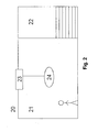
- the FIG. 2 shows the possible hoist positions 20, which can be assigned to either the working area 21 or the safe area 22.
- the work area 21 is the area where the hoist 23 moves with the load 24 when the brake test was successful. This area is suitable for the stay of persons, because the load is secured against uncontrolled sinking.
- the safe area 22 is closed by security means for persons. Here is the stay of people prevented.
- a brake test is carried out in the hoisting gear 23, then the hoisting gear is moved into this safe area 22 and the brake test is carried out. If the test is positive, the hoist can continue its work, ie in particular to carry out its movement into the working area 21. In the event that the brake test is negative, the load 24 is discontinued in this area. The faulty brake can be maintained in this position in a simple and safe way. Subsequently, the hoist 23 is again in operation after a new brake test.
- FIG. 3 shows a further embodiment of the device according to the invention.
- the arrangement and equipment of the drives is the description of FIG. 1 corresponding.
- FIG. 3 shows the interconnection of the motors 1 and the brakes 2, which are not directly connected to the frequency converter 4 and the supply line 14 electrically connected.
- the contactors 7, 8, 9, 10, 31, 32 shown in the figure represent a network which maps three levels of the safe circuit of the hoist.
- the brakes 2 are designed so that they are closed when de-energized. To enable a movement of the drives, so the brake 2 must be energized.
- the supply of the brakes 2 takes place from the supply line 14, in which case the contactors 8, 9 and 10 are interposed.
- the contactor 8 disconnects the network of contactors necessary for energizing the brakes 2 from the supply line 14. This contactor 8 is switched by the monitoring module 6. If there is no fault registered on the hoist in this, the contactor 8 switches on Passage, so that the brakes can be operated with the supply voltage. When switched contactor 8, the supply voltage is applied to the contactor 9.
- a signal is required, which is provided by the monitoring module 6.
- the frequency converter 4 In order to pass this through to the contactor 9, the frequency converter 4 must release it to the contactor 32. If the contactor 32 is switched through, then the signal of the monitoring module 6 is applied to the contactor 10. If the contactor 10 is switched by the controller 12, this obtains a circuit of the contactor 9, whereby an opening of the brake 2 is effected.
- the network is thus designed to logically link such operating conditions.
- the release of the motors 1 also takes place according to a multi-stage process.
- the motors 1 must be released in the frequency converter 4, which is not shown in the figure.
- the contactor 7 is inserted, which is switched by the contactor 31.
- a signal from the monitoring module 6 must rest on the contactor 31, which presupposes that there are no safety problems. only then can the contactor 31 be switched by the controller 12, so that the contactor 7 is switched through and the motor can go into operation.
- the network is thus designed to logically link such operating conditions.
- the brake 2 can be closed and the motor 1 can be energized by the frequency converter 4 in a drive. If no angular change is detected when a limit torque is built up on the motor encoder 3, then the brake is considered safe up to this limit torque.
Landscapes
- Engineering & Computer Science (AREA)
- Mechanical Engineering (AREA)
- Control And Safety Of Cranes (AREA)
- Electric Propulsion And Braking For Vehicles (AREA)
- Stopping Of Electric Motors (AREA)
Claims (12)
- Agencement dévolu au fonctionnement en sûreté d'un mécanisme de levage, en particulier d'un mécanisme de levage à vitesse régulée, sachant- qu'un unique variateur, incluant une unité de régulation, alimente au moins deux entraînements,- que chaque entraînement comprend un moteur, un frein et au moins un capteur respectif, notamment un capteur angulaire, conçu pour détecter une grandeur physique d'état dudit entraînement,- que les signaux de détection du capteur d'un entraînement sont appliqués à ladite unité de régulation,- que les moteurs desdits entraînements sont montés en parallèle et des moyens, affectés à la détection du courant de sortie du variateur, sont raccordés à l'unité de régulation dudit variateur,- que lesdits entraînements sont couplés mutuellement en mode mécanique, de façon telle qu'en cas de défaillance d'un entraînement, l'autre ou les autres entraînement(s), monté(s) en parallèle, prenne(nt) en charge la génération de couples de rotation,- que le signal de détection du premier entraînement et de l'autre entraînement, ou des autres entraînements, est également transmis à un module renfermant des moyens d'analyse des signaux de détection, en vue d'engendrer un signal de sortie,- que ledit variateur inclut des moyens affectés à la génération d'un signal d'activation des freins,- que ledit signal de sortie et ledit signal d'activation des freins sont appliqués à un réseau d'éléments de commutation activables, notamment de contacteurs, qui est réalisé de telle sorte que la délivrance de courant aux moteurs puisse être autorisée ou interrompue, et que les freins puissent être activés ou désactivés et puissent, en particulier, être raccordés avec alimentation en courant ou avec privation de courant,caractérisé par le fait que
des signaux d'activation des moteurs et des signaux d'activation des freins d'une commande prioritaire sont appliqués au réseau. - Agencement selon la revendication 1,
caractérisé par le fait
qu'un arbre est entraîné en commun par tous les entraînements, en vue du couplage mécanique. - Agencement selon l'une des revendications précédentes,
caractérisé par le fait que
le réseau est réalisé de telle sorte que du courant soit fourni, au moteur considéré, uniquement lorsque le signal de sortie du module et, le cas échéant, un signal d'activation de moteur d'une commande prioritaire, associé de manière correspondante, accordent une autorisation. - Agencement selon l'une des revendications précédentes,
caractérisé par le fait que
le réseau est réalisé de telle sorte que le frein considéré soit activé uniquement lorsque le signal de sortie du module, le signal d'activation de frein du variateur et, le cas échéant, un signal d'activation de frein d'une commande prioritaire, associé de manière correspondante, accordent une autorisation. - Agencement selon l'une des revendications précédentes,
caractérisé par le fait que
le capteur angulaire est connecté à un arbre, en particulier à un arbre du rotor d'un moteur électrique ou à l'arbre entraîné en commun. - Agencement selon l'une des revendications précédentes,
caractérisé par le fait que
le réseau est réalisé de telle sorte qu'une combinaison logique d'états fonctionnels soit instaurée. - Agencement selon l'une des revendications précédentes,
caractérisé par le fait que
le variateur, la commande prioritaire et/ou le module sont raccordés mutuellement, en vue de la transmission de données. - Agencement selon l'une des revendications précédentes,
caractérisé par le fait que
des moyens sont prévus pour imprimer des mouvements au mécanisme de levage vers différents emplacements dudit mécanisme de levage, à l'intérieur de l'installation,
et/ou
que chaque emplacement dudit mécanisme de levage est compris dans une zone de travail ou dans une zone sécurisée, répondant à des impératifs de sûreté différents, sachant notamment que le séjour de personnes est interdit dans ladite zone sécurisée prévue pour le dépôt des charges en sûreté, et/ou que ladite zone sécurisée est surveillée, en vue du séjour de personnes, par des moyens de sûreté connectés à une commande prioritaire et/ou au variateur,
et/ou
que des moyens sont prévus pour afficher la sûreté de l'installation. - Procédé destiné au fonctionnement en sûreté d'une installation équipée d'un dispositif de sûreté,
ladite installation incluant des entraînements couplés mécaniquement qui comprennent, respectivement, un frein et un capteur angulaire,
sachant que lesdits entraînements font l'objet d'une vérification des freins englobant les étapes suivantes :- tous les freins à vérifier dans les entraînements couplés, à l'exception d'au moins l'un d'entre eux, sont désaérés lors d'une première étape,- lesdits entraînements couplés sont mis en marche lors d'une deuxième étape,- la position angulaire d'un arbre desdits entraînements est comparée, lors d'une troisième étape, concernant notamment la concordance avec la valeur de consigne. - Procédé selon la revendication 9,
caractérisé par le fait que
l'état effectif de l'installation est visualisé par un moyen d'affichage,
et/ou
que la vérification des freins est effectuée dans une zone sécurisée, notamment pas dans la zone de travail,
et/ou
que ledit état effectif de l'installation est transmis à une commande prioritaire,
et/ou
qu'en l'absence de concordance des signaux de détection, un mécanisme de levage est amené à un emplacement situé dans une zone sécurisée, en particulier jusqu'à une zone dont l'accès est interdit à des personnes exposées à des risques. - Procédé selon l'une des revendications 9 ou 10,
caractérisé par le fait que
la vérification des freins est effectuée, en succession, sur les freins des entraînements couplés. - Procédé selon l'une des revendications 9, 11 ou 10,
caractérisé par le fait que
la commande prioritaire émet une instruction de déplacement, en vue de mouvoir les entraînements couplés vers un emplacement sécurisé,
ladite commande prioritaire déclenche la vérification des freins,
et ladite vérification des freins est exécutée par le variateur.
Priority Applications (1)
| Application Number | Priority Date | Filing Date | Title |
|---|---|---|---|
| EP13005015.6A EP2700607B1 (fr) | 2007-06-11 | 2008-06-03 | Agencement, module et procédé de fonctionnement sûr d'une installation |
Applications Claiming Priority (2)
| Application Number | Priority Date | Filing Date | Title |
|---|---|---|---|
| DE102007027351 | 2007-06-11 | ||
| PCT/EP2008/004427 WO2008151744A1 (fr) | 2007-06-11 | 2008-06-03 | Agencement, module et procédé pour le fonctionnement sûr d'une installation |
Related Child Applications (2)
| Application Number | Title | Priority Date | Filing Date |
|---|---|---|---|
| EP13005015.6A Division EP2700607B1 (fr) | 2007-06-11 | 2008-06-03 | Agencement, module et procédé de fonctionnement sûr d'une installation |
| EP13005015.6A Division-Into EP2700607B1 (fr) | 2007-06-11 | 2008-06-03 | Agencement, module et procédé de fonctionnement sûr d'une installation |
Publications (2)
| Publication Number | Publication Date |
|---|---|
| EP2160349A1 EP2160349A1 (fr) | 2010-03-10 |
| EP2160349B1 true EP2160349B1 (fr) | 2015-04-08 |
Family
ID=39736567
Family Applications (2)
| Application Number | Title | Priority Date | Filing Date |
|---|---|---|---|
| EP13005015.6A Active EP2700607B1 (fr) | 2007-06-11 | 2008-06-03 | Agencement, module et procédé de fonctionnement sûr d'une installation |
| EP08758988.3A Active EP2160349B1 (fr) | 2007-06-11 | 2008-06-03 | Agencement, module et procédé pour le fonctionnement sûr d'une installation |
Family Applications Before (1)
| Application Number | Title | Priority Date | Filing Date |
|---|---|---|---|
| EP13005015.6A Active EP2700607B1 (fr) | 2007-06-11 | 2008-06-03 | Agencement, module et procédé de fonctionnement sûr d'une installation |
Country Status (4)
| Country | Link |
|---|---|
| EP (2) | EP2700607B1 (fr) |
| CN (3) | CN101679008B (fr) |
| DE (1) | DE102008026465B4 (fr) |
| WO (1) | WO2008151744A1 (fr) |
Families Citing this family (8)
| Publication number | Priority date | Publication date | Assignee | Title |
|---|---|---|---|---|
| DE102009007559B4 (de) * | 2009-02-04 | 2017-07-06 | Sew-Eurodrive Gmbh & Co Kg | Antriebssystem, Mehrfachantriebssystem, Verfahren zum Überprüfen eines Antriebssystems oder Mehrfachantriebssystems, Verfahren zur Inbetriebnahme einer Maschine, Maschine mit einem Antriebssystem oder Mehrfachantriebssystem, Computerprogramm und –produkt |
| DE102014001988B4 (de) * | 2014-02-17 | 2018-01-11 | Sew-Eurodrive Gmbh & Co Kg | Antriebssystem mit zumindest zwei eine Last antreibenden Motoren und zumindest einer ersten Bremse und Verfahren zur Dimensionierung eines Bremsmotors zum Antreiben einer Last |
| AU2015263842B2 (en) * | 2014-05-23 | 2020-02-27 | Jands Pty Ltd | An electromechanical hoist for eliminating the possibility of loss of control of a load following a single point failure in a drive train and a method of operation thereof |
| CN104460478A (zh) * | 2014-11-11 | 2015-03-25 | 沈阳新松机器人自动化股份有限公司 | 一种工业机器人抱闸监控方法及装置 |
| DE102015010174A1 (de) * | 2015-08-06 | 2017-02-09 | Esw Gmbh | Seilwinde für ein Fluggerät oder Fahrzeug und Verfahren zum Überprüfen einer Seilwinde für ein Fluggerät oder Fahrzeug |
| FR3072924B1 (fr) * | 2017-10-30 | 2019-10-25 | Safran Landing Systems | Equipement electrique destine a etre relie a un actionneur electromecanique de freinage et a un actionneur electromecanique d'entrainement |
| CN113816272B (zh) * | 2021-09-17 | 2023-11-03 | 安徽安久模架科技有限公司 | 一种带有自动控制系统的电动提升机 |
| CN114460896A (zh) * | 2022-01-11 | 2022-05-10 | 首钢京唐钢铁联合有限责任公司 | 炼钢脱硫搅拌头升降控制装置及方法 |
Family Cites Families (11)
| Publication number | Priority date | Publication date | Assignee | Title |
|---|---|---|---|---|
| DE3137523A1 (de) | 1981-09-22 | 1983-04-28 | Mannesmann AG, 4000 Düsseldorf | Sicherheitseinrichtung fuer ein hebezeug |
| US4487741A (en) * | 1981-11-30 | 1984-12-11 | Westinghouse Electric Corp. | Transfer of fuel assemblies |
| DE3729064C2 (de) * | 1987-08-31 | 2003-01-09 | Tax Ingenieurgmbh | Redundantes Windensystem |
| DE3933505A1 (de) * | 1988-10-08 | 1990-04-12 | Man Ghh Krantechnik | Hubwerk |
| DE3838058C3 (de) | 1988-11-07 | 1996-04-11 | Mannesmann Ag | Antriebsüberwachung einer Antriebskette |
| DE9013918U1 (fr) | 1989-10-06 | 1991-05-16 | Man Ghh Logistics Gmbh, 7100 Heilbronn, De | |
| CN1206155C (zh) * | 2001-05-25 | 2005-06-15 | 太原重型机械(集团)有限公司 | 一种起重机的起升机构 |
| DE10339440A1 (de) * | 2003-08-25 | 2005-04-07 | Demag Cranes & Components Gmbh | Verfahren zur Überwachung eines Kettenzuges und Kettenzug |
| CN2709520Y (zh) * | 2004-03-12 | 2005-07-13 | 江万宁 | 钢丝绳卷扬提升垂直升船机的安全装置 |
| DE102004039151A1 (de) * | 2004-08-12 | 2006-02-23 | Wabco Gmbh & Co.Ohg | Brake-Performance-Üerwachung |
| CN1752726A (zh) * | 2004-09-20 | 2006-03-29 | 交通部公路科学研究所 | 测量车轮滑动率的方法以及实现该方法的检测装置 |
-
2008
- 2008-06-03 DE DE102008026465.2A patent/DE102008026465B4/de active Active
- 2008-06-03 EP EP13005015.6A patent/EP2700607B1/fr active Active
- 2008-06-03 CN CN2008800199569A patent/CN101679008B/zh active Active
- 2008-06-03 CN CN201210147048.6A patent/CN102674183B/zh active Active
- 2008-06-03 CN CN201210147067.9A patent/CN102674184B/zh active Active
- 2008-06-03 EP EP08758988.3A patent/EP2160349B1/fr active Active
- 2008-06-03 WO PCT/EP2008/004427 patent/WO2008151744A1/fr active Application Filing
Also Published As
| Publication number | Publication date |
|---|---|
| CN101679008B (zh) | 2013-08-21 |
| CN102674183A (zh) | 2012-09-19 |
| EP2700607A2 (fr) | 2014-02-26 |
| DE102008026465A1 (de) | 2008-12-18 |
| CN102674184A (zh) | 2012-09-19 |
| CN101679008A (zh) | 2010-03-24 |
| EP2700607A3 (fr) | 2014-03-26 |
| CN102674183B (zh) | 2015-10-14 |
| EP2700607B1 (fr) | 2015-09-09 |
| EP2160349A1 (fr) | 2010-03-10 |
| DE102008026465B4 (de) | 2018-01-11 |
| WO2008151744A1 (fr) | 2008-12-18 |
| CN102674184B (zh) | 2015-07-08 |
Similar Documents
| Publication | Publication Date | Title |
|---|---|---|
| EP2160349B1 (fr) | Agencement, module et procédé pour le fonctionnement sûr d'une installation | |
| EP2022742B1 (fr) | Système d'ascenseur | |
| EP2785626B1 (fr) | Frein de sécurité avec moyen de rappel | |
| DE102006034962B4 (de) | Verfahren zum gesicherten Bremsen eines Tores sowie Vorrichtung zur Durchführung des Verfahrens | |
| DE112009004592B4 (de) | Aufzuganlage und Verfahren zum Überprüfen derselben | |
| EP3353108B1 (fr) | Dispositif de surveillance d'ascenseur | |
| EP2359466B1 (fr) | Procédé de fonctionnement d'un entraînement, ainsi qu'entraînement | |
| DE112010002756B4 (de) | Aufzugvorrichtung | |
| DE112016006975T5 (de) | Sicherheitssteuerungsvorrichtung und Sicherheitssteuerungsverfahren für einen Mehrfachkabinenaufzug | |
| DE29924639U1 (de) | Aufzugsanlage mit einer Vorrichtung zum Sonderbetrieb | |
| EP1380533B1 (fr) | Dispositif de commande pour convoyeur aérien | |
| DE10233873B4 (de) | Steuerung für eine Krananlage, insbesondere einen Containerkran | |
| DE4327848C2 (de) | Steuereinrichtung für eine Druckmaschine | |
| EP3704048B1 (fr) | Dispositif de surveillance de sécurité destiné à surveiller des conditions relatives à la sécurité dans une installation de transport de personnes ainsi que procédé de fonctionnement d'un tel dispositif | |
| EP2126536B1 (fr) | Dispositif et procédé pour un test de fonctionnement d'un frein | |
| DE102010051413B4 (de) | Antriebssystem und Verfahren zum Betreiben eines Antriebssystems für eine Achse einer Maschine oder eine Anlage | |
| EP2047171B2 (fr) | Procede destine a proteger des personnes dans le cadre de leur travail sur une servopresse, et servopresse comprenant un dispositif de protection des personnes | |
| DE19522447C2 (de) | Kaskadierbare Überwachungseinrichtung | |
| DE102017204123A1 (de) | Verfahren zum Bremsen einer Maschine und Maschine | |
| EP3301051A1 (fr) | Ascenseur comprenant un éclairage de cage | |
| DE10354591B4 (de) | Aufzuganlage | |
| DE102019000422A1 (de) | Verfahren zum Test eines Antriebssystems mit einer Ersten Bremse und Antriebssystem | |
| EP4214149A1 (fr) | Dispositif de sécurité pour la commande de fonctions ucm et udm relatives à la sécurité dans un système d'ascenseur | |
| DE102010011788A1 (de) | Verfahren zum Betreiben eines Antriebssystem und Antriebssystem | |
| DE19951169A1 (de) | Personenaufzuganlage |
Legal Events
| Date | Code | Title | Description |
|---|---|---|---|
| PUAI | Public reference made under article 153(3) epc to a published international application that has entered the european phase |
Free format text: ORIGINAL CODE: 0009012 |
|
| 17P | Request for examination filed |
Effective date: 20100111 |
|
| AK | Designated contracting states |
Kind code of ref document: A1 Designated state(s): AT BE BG CH CY CZ DE DK EE ES FI FR GB GR HR HU IE IS IT LI LT LU LV MC MT NL NO PL PT RO SE SI SK TR |
|
| AX | Request for extension of the european patent |
Extension state: AL BA MK RS |
|
| DAX | Request for extension of the european patent (deleted) | ||
| 17Q | First examination report despatched |
Effective date: 20130611 |
|
| GRAP | Despatch of communication of intention to grant a patent |
Free format text: ORIGINAL CODE: EPIDOSNIGR1 |
|
| INTG | Intention to grant announced |
Effective date: 20141021 |
|
| GRAP | Despatch of communication of intention to grant a patent |
Free format text: ORIGINAL CODE: EPIDOSNIGR1 |
|
| GRAS | Grant fee paid |
Free format text: ORIGINAL CODE: EPIDOSNIGR3 |
|
| GRAA | (expected) grant |
Free format text: ORIGINAL CODE: 0009210 |
|
| INTG | Intention to grant announced |
Effective date: 20150220 |
|
| AK | Designated contracting states |
Kind code of ref document: B1 Designated state(s): AT BE BG CH CY CZ DE DK EE ES FI FR GB GR HR HU IE IS IT LI LT LU LV MC MT NL NO PL PT RO SE SI SK TR |
|
| REG | Reference to a national code |
Ref country code: GB Ref legal event code: FG4D Free format text: NOT ENGLISH |
|
| REG | Reference to a national code |
Ref country code: CH Ref legal event code: EP |
|
| REG | Reference to a national code |
Ref country code: IE Ref legal event code: FG4D Free format text: LANGUAGE OF EP DOCUMENT: GERMAN |
|
| REG | Reference to a national code |
Ref country code: AT Ref legal event code: REF Ref document number: 720407 Country of ref document: AT Kind code of ref document: T Effective date: 20150515 |
|
| REG | Reference to a national code |
Ref country code: DE Ref legal event code: R096 Ref document number: 502008012866 Country of ref document: DE Effective date: 20150521 |
|
| REG | Reference to a national code |
Ref country code: NL Ref legal event code: VDEP Effective date: 20150408 |
|
| REG | Reference to a national code |
Ref country code: LT Ref legal event code: MG4D |
|
| PG25 | Lapsed in a contracting state [announced via postgrant information from national office to epo] |
Ref country code: NL Free format text: LAPSE BECAUSE OF FAILURE TO SUBMIT A TRANSLATION OF THE DESCRIPTION OR TO PAY THE FEE WITHIN THE PRESCRIBED TIME-LIMIT Effective date: 20150408 |
|
| PG25 | Lapsed in a contracting state [announced via postgrant information from national office to epo] |
Ref country code: NO Free format text: LAPSE BECAUSE OF FAILURE TO SUBMIT A TRANSLATION OF THE DESCRIPTION OR TO PAY THE FEE WITHIN THE PRESCRIBED TIME-LIMIT Effective date: 20150708 Ref country code: PT Free format text: LAPSE BECAUSE OF FAILURE TO SUBMIT A TRANSLATION OF THE DESCRIPTION OR TO PAY THE FEE WITHIN THE PRESCRIBED TIME-LIMIT Effective date: 20150810 Ref country code: FI Free format text: LAPSE BECAUSE OF FAILURE TO SUBMIT A TRANSLATION OF THE DESCRIPTION OR TO PAY THE FEE WITHIN THE PRESCRIBED TIME-LIMIT Effective date: 20150408 Ref country code: LT Free format text: LAPSE BECAUSE OF FAILURE TO SUBMIT A TRANSLATION OF THE DESCRIPTION OR TO PAY THE FEE WITHIN THE PRESCRIBED TIME-LIMIT Effective date: 20150408 Ref country code: ES Free format text: LAPSE BECAUSE OF FAILURE TO SUBMIT A TRANSLATION OF THE DESCRIPTION OR TO PAY THE FEE WITHIN THE PRESCRIBED TIME-LIMIT Effective date: 20150408 Ref country code: HR Free format text: LAPSE BECAUSE OF FAILURE TO SUBMIT A TRANSLATION OF THE DESCRIPTION OR TO PAY THE FEE WITHIN THE PRESCRIBED TIME-LIMIT Effective date: 20150408 |
|
| PG25 | Lapsed in a contracting state [announced via postgrant information from national office to epo] |
Ref country code: GR Free format text: LAPSE BECAUSE OF FAILURE TO SUBMIT A TRANSLATION OF THE DESCRIPTION OR TO PAY THE FEE WITHIN THE PRESCRIBED TIME-LIMIT Effective date: 20150709 Ref country code: IS Free format text: LAPSE BECAUSE OF FAILURE TO SUBMIT A TRANSLATION OF THE DESCRIPTION OR TO PAY THE FEE WITHIN THE PRESCRIBED TIME-LIMIT Effective date: 20150808 Ref country code: LV Free format text: LAPSE BECAUSE OF FAILURE TO SUBMIT A TRANSLATION OF THE DESCRIPTION OR TO PAY THE FEE WITHIN THE PRESCRIBED TIME-LIMIT Effective date: 20150408 |
|
| REG | Reference to a national code |
Ref country code: DE Ref legal event code: R097 Ref document number: 502008012866 Country of ref document: DE |
|
| PG25 | Lapsed in a contracting state [announced via postgrant information from national office to epo] |
Ref country code: MC Free format text: LAPSE BECAUSE OF FAILURE TO SUBMIT A TRANSLATION OF THE DESCRIPTION OR TO PAY THE FEE WITHIN THE PRESCRIBED TIME-LIMIT Effective date: 20150408 Ref country code: IT Free format text: LAPSE BECAUSE OF FAILURE TO SUBMIT A TRANSLATION OF THE DESCRIPTION OR TO PAY THE FEE WITHIN THE PRESCRIBED TIME-LIMIT Effective date: 20150408 Ref country code: DK Free format text: LAPSE BECAUSE OF FAILURE TO SUBMIT A TRANSLATION OF THE DESCRIPTION OR TO PAY THE FEE WITHIN THE PRESCRIBED TIME-LIMIT Effective date: 20150408 Ref country code: EE Free format text: LAPSE BECAUSE OF FAILURE TO SUBMIT A TRANSLATION OF THE DESCRIPTION OR TO PAY THE FEE WITHIN THE PRESCRIBED TIME-LIMIT Effective date: 20150408 |
|
| REG | Reference to a national code |
Ref country code: CH Ref legal event code: PL |
|
| PLBE | No opposition filed within time limit |
Free format text: ORIGINAL CODE: 0009261 |
|
| STAA | Information on the status of an ep patent application or granted ep patent |
Free format text: STATUS: NO OPPOSITION FILED WITHIN TIME LIMIT |
|
| PG25 | Lapsed in a contracting state [announced via postgrant information from national office to epo] |
Ref country code: SK Free format text: LAPSE BECAUSE OF FAILURE TO SUBMIT A TRANSLATION OF THE DESCRIPTION OR TO PAY THE FEE WITHIN THE PRESCRIBED TIME-LIMIT Effective date: 20150408 Ref country code: PL Free format text: LAPSE BECAUSE OF FAILURE TO SUBMIT A TRANSLATION OF THE DESCRIPTION OR TO PAY THE FEE WITHIN THE PRESCRIBED TIME-LIMIT Effective date: 20150408 Ref country code: CZ Free format text: LAPSE BECAUSE OF FAILURE TO SUBMIT A TRANSLATION OF THE DESCRIPTION OR TO PAY THE FEE WITHIN THE PRESCRIBED TIME-LIMIT Effective date: 20150408 Ref country code: LU Free format text: LAPSE BECAUSE OF FAILURE TO SUBMIT A TRANSLATION OF THE DESCRIPTION OR TO PAY THE FEE WITHIN THE PRESCRIBED TIME-LIMIT Effective date: 20150603 Ref country code: RO Free format text: LAPSE BECAUSE OF NON-PAYMENT OF DUE FEES Effective date: 20150408 |
|
| 26N | No opposition filed |
Effective date: 20160111 |
|
| REG | Reference to a national code |
Ref country code: IE Ref legal event code: MM4A |
|
| PG25 | Lapsed in a contracting state [announced via postgrant information from national office to epo] |
Ref country code: LI Free format text: LAPSE BECAUSE OF NON-PAYMENT OF DUE FEES Effective date: 20150630 Ref country code: IE Free format text: LAPSE BECAUSE OF NON-PAYMENT OF DUE FEES Effective date: 20150603 Ref country code: CH Free format text: LAPSE BECAUSE OF NON-PAYMENT OF DUE FEES Effective date: 20150630 |
|
| REG | Reference to a national code |
Ref country code: FR Ref legal event code: PLFP Year of fee payment: 9 |
|
| PG25 | Lapsed in a contracting state [announced via postgrant information from national office to epo] |
Ref country code: SI Free format text: LAPSE BECAUSE OF FAILURE TO SUBMIT A TRANSLATION OF THE DESCRIPTION OR TO PAY THE FEE WITHIN THE PRESCRIBED TIME-LIMIT Effective date: 20150408 |
|
| REG | Reference to a national code |
Ref country code: AT Ref legal event code: MM01 Ref document number: 720407 Country of ref document: AT Kind code of ref document: T Effective date: 20150603 |
|
| PG25 | Lapsed in a contracting state [announced via postgrant information from national office to epo] |
Ref country code: AT Free format text: LAPSE BECAUSE OF NON-PAYMENT OF DUE FEES Effective date: 20150603 |
|
| PG25 | Lapsed in a contracting state [announced via postgrant information from national office to epo] |
Ref country code: MT Free format text: LAPSE BECAUSE OF FAILURE TO SUBMIT A TRANSLATION OF THE DESCRIPTION OR TO PAY THE FEE WITHIN THE PRESCRIBED TIME-LIMIT Effective date: 20150408 |
|
| REG | Reference to a national code |
Ref country code: FR Ref legal event code: PLFP Year of fee payment: 10 |
|
| PG25 | Lapsed in a contracting state [announced via postgrant information from national office to epo] |
Ref country code: BG Free format text: LAPSE BECAUSE OF FAILURE TO SUBMIT A TRANSLATION OF THE DESCRIPTION OR TO PAY THE FEE WITHIN THE PRESCRIBED TIME-LIMIT Effective date: 20150408 Ref country code: HU Free format text: LAPSE BECAUSE OF FAILURE TO SUBMIT A TRANSLATION OF THE DESCRIPTION OR TO PAY THE FEE WITHIN THE PRESCRIBED TIME-LIMIT; INVALID AB INITIO Effective date: 20080603 |
|
| PG25 | Lapsed in a contracting state [announced via postgrant information from national office to epo] |
Ref country code: SE Free format text: LAPSE BECAUSE OF FAILURE TO SUBMIT A TRANSLATION OF THE DESCRIPTION OR TO PAY THE FEE WITHIN THE PRESCRIBED TIME-LIMIT Effective date: 20150408 Ref country code: CY Free format text: LAPSE BECAUSE OF FAILURE TO SUBMIT A TRANSLATION OF THE DESCRIPTION OR TO PAY THE FEE WITHIN THE PRESCRIBED TIME-LIMIT Effective date: 20150408 |
|
| PG25 | Lapsed in a contracting state [announced via postgrant information from national office to epo] |
Ref country code: BE Free format text: LAPSE BECAUSE OF NON-PAYMENT OF DUE FEES Effective date: 20150630 |
|
| PG25 | Lapsed in a contracting state [announced via postgrant information from national office to epo] |
Ref country code: TR Free format text: LAPSE BECAUSE OF FAILURE TO SUBMIT A TRANSLATION OF THE DESCRIPTION OR TO PAY THE FEE WITHIN THE PRESCRIBED TIME-LIMIT Effective date: 20150408 |
|
| REG | Reference to a national code |
Ref country code: FR Ref legal event code: PLFP Year of fee payment: 11 |
|
| PGFP | Annual fee paid to national office [announced via postgrant information from national office to epo] |
Ref country code: FR Payment date: 20230510 Year of fee payment: 16 Ref country code: DE Payment date: 20230630 Year of fee payment: 16 |
|
| PGFP | Annual fee paid to national office [announced via postgrant information from national office to epo] |
Ref country code: GB Payment date: 20230504 Year of fee payment: 16 |