EP2154458A2 - Energieeffiziente, kostengünstige Extraktion von Sauerstoff aus der Umgebungsluft für tragbare Geräte und den Hausgebrauch - Google Patents
Energieeffiziente, kostengünstige Extraktion von Sauerstoff aus der Umgebungsluft für tragbare Geräte und den Hausgebrauch Download PDFInfo
- Publication number
- EP2154458A2 EP2154458A2 EP09176935A EP09176935A EP2154458A2 EP 2154458 A2 EP2154458 A2 EP 2154458A2 EP 09176935 A EP09176935 A EP 09176935A EP 09176935 A EP09176935 A EP 09176935A EP 2154458 A2 EP2154458 A2 EP 2154458A2
- Authority
- EP
- European Patent Office
- Prior art keywords
- oxygen
- vessel
- air
- incoming air
- gases
- Prior art date
- Legal status (The legal status is an assumption and is not a legal conclusion. Google has not performed a legal analysis and makes no representation as to the accuracy of the status listed.)
- Withdrawn
Links
- QVGXLLKOCUKJST-UHFFFAOYSA-N atomic oxygen Chemical compound [O] QVGXLLKOCUKJST-UHFFFAOYSA-N 0.000 title claims abstract description 106
- 239000001301 oxygen Substances 0.000 title claims abstract description 106
- 229910052760 oxygen Inorganic materials 0.000 title claims abstract description 106
- 239000012080 ambient air Substances 0.000 title description 19
- 238000000605 extraction Methods 0.000 title description 2
- 239000007789 gas Substances 0.000 claims abstract description 94
- XLYOFNOQVPJJNP-UHFFFAOYSA-N water Substances O XLYOFNOQVPJJNP-UHFFFAOYSA-N 0.000 claims abstract description 51
- IJGRMHOSHXDMSA-UHFFFAOYSA-N Atomic nitrogen Chemical compound N#N IJGRMHOSHXDMSA-UHFFFAOYSA-N 0.000 claims abstract description 32
- 238000001816 cooling Methods 0.000 claims abstract description 20
- 238000000034 method Methods 0.000 claims abstract description 18
- 238000009835 boiling Methods 0.000 claims abstract description 16
- 229910052757 nitrogen Inorganic materials 0.000 claims abstract description 16
- 238000007710 freezing Methods 0.000 claims description 5
- 230000008014 freezing Effects 0.000 claims description 5
- 238000001704 evaporation Methods 0.000 claims 1
- 239000003570 air Substances 0.000 description 70
- 238000000926 separation method Methods 0.000 description 22
- 239000007788 liquid Substances 0.000 description 21
- MYMOFIZGZYHOMD-UHFFFAOYSA-N Dioxygen Chemical compound O=O MYMOFIZGZYHOMD-UHFFFAOYSA-N 0.000 description 13
- 230000008901 benefit Effects 0.000 description 8
- 238000007906 compression Methods 0.000 description 8
- 230000006835 compression Effects 0.000 description 8
- 239000000470 constituent Substances 0.000 description 6
- 230000008569 process Effects 0.000 description 5
- 239000000203 mixture Substances 0.000 description 4
- 230000004888 barrier function Effects 0.000 description 3
- 230000008859 change Effects 0.000 description 3
- 238000009833 condensation Methods 0.000 description 3
- 230000005494 condensation Effects 0.000 description 3
- 238000010586 diagram Methods 0.000 description 3
- 238000009826 distribution Methods 0.000 description 3
- 230000005484 gravity Effects 0.000 description 3
- 238000004519 manufacturing process Methods 0.000 description 3
- 239000002826 coolant Substances 0.000 description 2
- 239000012530 fluid Substances 0.000 description 2
- 239000012528 membrane Substances 0.000 description 2
- 238000011084 recovery Methods 0.000 description 2
- 230000029058 respiratory gaseous exchange Effects 0.000 description 2
- 238000003860 storage Methods 0.000 description 2
- 230000000274 adsorptive effect Effects 0.000 description 1
- 238000010420 art technique Methods 0.000 description 1
- 238000006243 chemical reaction Methods 0.000 description 1
- 238000005265 energy consumption Methods 0.000 description 1
- LYCAIKOWRPUZTN-UHFFFAOYSA-N ethylene glycol Natural products OCCO LYCAIKOWRPUZTN-UHFFFAOYSA-N 0.000 description 1
- 125000002485 formyl group Chemical class [H]C(*)=O 0.000 description 1
- -1 glycol compound Chemical class 0.000 description 1
- WGCNASOHLSPBMP-UHFFFAOYSA-N hydroxyacetaldehyde Natural products OCC=O WGCNASOHLSPBMP-UHFFFAOYSA-N 0.000 description 1
- 238000009413 insulation Methods 0.000 description 1
- 239000011159 matrix material Substances 0.000 description 1
- 238000012986 modification Methods 0.000 description 1
- 230000004048 modification Effects 0.000 description 1
- 230000003071 parasitic effect Effects 0.000 description 1
- 230000000704 physical effect Effects 0.000 description 1
- 230000005855 radiation Effects 0.000 description 1
- 238000011144 upstream manufacturing Methods 0.000 description 1
- 239000003039 volatile agent Substances 0.000 description 1
Images

Classifications
-
- F—MECHANICAL ENGINEERING; LIGHTING; HEATING; WEAPONS; BLASTING
- F25—REFRIGERATION OR COOLING; COMBINED HEATING AND REFRIGERATION SYSTEMS; HEAT PUMP SYSTEMS; MANUFACTURE OR STORAGE OF ICE; LIQUEFACTION SOLIDIFICATION OF GASES
- F25J—LIQUEFACTION, SOLIDIFICATION OR SEPARATION OF GASES OR GASEOUS OR LIQUEFIED GASEOUS MIXTURES BY PRESSURE AND COLD TREATMENT OR BY BRINGING THEM INTO THE SUPERCRITICAL STATE
- F25J3/00—Processes or apparatus for separating the constituents of gaseous or liquefied gaseous mixtures involving the use of liquefaction or solidification
- F25J3/02—Processes or apparatus for separating the constituents of gaseous or liquefied gaseous mixtures involving the use of liquefaction or solidification by rectification, i.e. by continuous interchange of heat and material between a vapour stream and a liquid stream
- F25J3/04—Processes or apparatus for separating the constituents of gaseous or liquefied gaseous mixtures involving the use of liquefaction or solidification by rectification, i.e. by continuous interchange of heat and material between a vapour stream and a liquid stream for air
- F25J3/04763—Start-up or control of the process; Details of the apparatus used
- F25J3/04866—Construction and layout of air fractionation equipments, e.g. valves, machines
- F25J3/04975—Construction and layout of air fractionation equipments, e.g. valves, machines adapted for special use of the air fractionation unit, e.g. transportable devices by truck or small scale use
- F25J3/04981—Construction and layout of air fractionation equipments, e.g. valves, machines adapted for special use of the air fractionation unit, e.g. transportable devices by truck or small scale use for portable medical or home use
-
- F—MECHANICAL ENGINEERING; LIGHTING; HEATING; WEAPONS; BLASTING
- F25—REFRIGERATION OR COOLING; COMBINED HEATING AND REFRIGERATION SYSTEMS; HEAT PUMP SYSTEMS; MANUFACTURE OR STORAGE OF ICE; LIQUEFACTION SOLIDIFICATION OF GASES
- F25J—LIQUEFACTION, SOLIDIFICATION OR SEPARATION OF GASES OR GASEOUS OR LIQUEFIED GASEOUS MIXTURES BY PRESSURE AND COLD TREATMENT OR BY BRINGING THEM INTO THE SUPERCRITICAL STATE
- F25J1/00—Processes or apparatus for liquefying or solidifying gases or gaseous mixtures
-
- A—HUMAN NECESSITIES
- A61—MEDICAL OR VETERINARY SCIENCE; HYGIENE
- A61M—DEVICES FOR INTRODUCING MEDIA INTO, OR ONTO, THE BODY; DEVICES FOR TRANSDUCING BODY MEDIA OR FOR TAKING MEDIA FROM THE BODY; DEVICES FOR PRODUCING OR ENDING SLEEP OR STUPOR
- A61M16/00—Devices for influencing the respiratory system of patients by gas treatment, e.g. ventilators; Tracheal tubes
- A61M16/10—Preparation of respiratory gases or vapours
- A61M16/1005—Preparation of respiratory gases or vapours with O2 features or with parameter measurement
- A61M16/101—Preparation of respiratory gases or vapours with O2 features or with parameter measurement using an oxygen concentrator
-
- F—MECHANICAL ENGINEERING; LIGHTING; HEATING; WEAPONS; BLASTING
- F25—REFRIGERATION OR COOLING; COMBINED HEATING AND REFRIGERATION SYSTEMS; HEAT PUMP SYSTEMS; MANUFACTURE OR STORAGE OF ICE; LIQUEFACTION SOLIDIFICATION OF GASES
- F25J—LIQUEFACTION, SOLIDIFICATION OR SEPARATION OF GASES OR GASEOUS OR LIQUEFIED GASEOUS MIXTURES BY PRESSURE AND COLD TREATMENT OR BY BRINGING THEM INTO THE SUPERCRITICAL STATE
- F25J3/00—Processes or apparatus for separating the constituents of gaseous or liquefied gaseous mixtures involving the use of liquefaction or solidification
- F25J3/02—Processes or apparatus for separating the constituents of gaseous or liquefied gaseous mixtures involving the use of liquefaction or solidification by rectification, i.e. by continuous interchange of heat and material between a vapour stream and a liquid stream
- F25J3/04—Processes or apparatus for separating the constituents of gaseous or liquefied gaseous mixtures involving the use of liquefaction or solidification by rectification, i.e. by continuous interchange of heat and material between a vapour stream and a liquid stream for air
- F25J3/04151—Purification and (pre-)cooling of the feed air; recuperative heat-exchange with product streams
- F25J3/04157—Afterstage cooling and so-called "pre-cooling" of the feed air upstream the air purification unit and main heat exchange line
-
- F—MECHANICAL ENGINEERING; LIGHTING; HEATING; WEAPONS; BLASTING
- F25—REFRIGERATION OR COOLING; COMBINED HEATING AND REFRIGERATION SYSTEMS; HEAT PUMP SYSTEMS; MANUFACTURE OR STORAGE OF ICE; LIQUEFACTION SOLIDIFICATION OF GASES
- F25J—LIQUEFACTION, SOLIDIFICATION OR SEPARATION OF GASES OR GASEOUS OR LIQUEFIED GASEOUS MIXTURES BY PRESSURE AND COLD TREATMENT OR BY BRINGING THEM INTO THE SUPERCRITICAL STATE
- F25J3/00—Processes or apparatus for separating the constituents of gaseous or liquefied gaseous mixtures involving the use of liquefaction or solidification
- F25J3/02—Processes or apparatus for separating the constituents of gaseous or liquefied gaseous mixtures involving the use of liquefaction or solidification by rectification, i.e. by continuous interchange of heat and material between a vapour stream and a liquid stream
- F25J3/04—Processes or apparatus for separating the constituents of gaseous or liquefied gaseous mixtures involving the use of liquefaction or solidification by rectification, i.e. by continuous interchange of heat and material between a vapour stream and a liquid stream for air
- F25J3/04151—Purification and (pre-)cooling of the feed air; recuperative heat-exchange with product streams
- F25J3/04163—Hot end purification of the feed air
-
- F—MECHANICAL ENGINEERING; LIGHTING; HEATING; WEAPONS; BLASTING
- F25—REFRIGERATION OR COOLING; COMBINED HEATING AND REFRIGERATION SYSTEMS; HEAT PUMP SYSTEMS; MANUFACTURE OR STORAGE OF ICE; LIQUEFACTION SOLIDIFICATION OF GASES
- F25J—LIQUEFACTION, SOLIDIFICATION OR SEPARATION OF GASES OR GASEOUS OR LIQUEFIED GASEOUS MIXTURES BY PRESSURE AND COLD TREATMENT OR BY BRINGING THEM INTO THE SUPERCRITICAL STATE
- F25J3/00—Processes or apparatus for separating the constituents of gaseous or liquefied gaseous mixtures involving the use of liquefaction or solidification
- F25J3/02—Processes or apparatus for separating the constituents of gaseous or liquefied gaseous mixtures involving the use of liquefaction or solidification by rectification, i.e. by continuous interchange of heat and material between a vapour stream and a liquid stream
- F25J3/04—Processes or apparatus for separating the constituents of gaseous or liquefied gaseous mixtures involving the use of liquefaction or solidification by rectification, i.e. by continuous interchange of heat and material between a vapour stream and a liquid stream for air
- F25J3/04151—Purification and (pre-)cooling of the feed air; recuperative heat-exchange with product streams
- F25J3/04242—Cold end purification of the feed air
-
- F—MECHANICAL ENGINEERING; LIGHTING; HEATING; WEAPONS; BLASTING
- F25—REFRIGERATION OR COOLING; COMBINED HEATING AND REFRIGERATION SYSTEMS; HEAT PUMP SYSTEMS; MANUFACTURE OR STORAGE OF ICE; LIQUEFACTION SOLIDIFICATION OF GASES
- F25J—LIQUEFACTION, SOLIDIFICATION OR SEPARATION OF GASES OR GASEOUS OR LIQUEFIED GASEOUS MIXTURES BY PRESSURE AND COLD TREATMENT OR BY BRINGING THEM INTO THE SUPERCRITICAL STATE
- F25J3/00—Processes or apparatus for separating the constituents of gaseous or liquefied gaseous mixtures involving the use of liquefaction or solidification
- F25J3/02—Processes or apparatus for separating the constituents of gaseous or liquefied gaseous mixtures involving the use of liquefaction or solidification by rectification, i.e. by continuous interchange of heat and material between a vapour stream and a liquid stream
- F25J3/04—Processes or apparatus for separating the constituents of gaseous or liquefied gaseous mixtures involving the use of liquefaction or solidification by rectification, i.e. by continuous interchange of heat and material between a vapour stream and a liquid stream for air
- F25J3/04248—Generation of cold for compensating heat leaks or liquid production, e.g. by Joule-Thompson expansion
- F25J3/04278—Generation of cold for compensating heat leaks or liquid production, e.g. by Joule-Thompson expansion using external refrigeration units, e.g. closed mechanical or regenerative refrigeration units
-
- A—HUMAN NECESSITIES
- A61—MEDICAL OR VETERINARY SCIENCE; HYGIENE
- A61M—DEVICES FOR INTRODUCING MEDIA INTO, OR ONTO, THE BODY; DEVICES FOR TRANSDUCING BODY MEDIA OR FOR TAKING MEDIA FROM THE BODY; DEVICES FOR PRODUCING OR ENDING SLEEP OR STUPOR
- A61M2202/00—Special media to be introduced, removed or treated
- A61M2202/02—Gases
- A61M2202/0208—Oxygen
-
- A—HUMAN NECESSITIES
- A61—MEDICAL OR VETERINARY SCIENCE; HYGIENE
- A61M—DEVICES FOR INTRODUCING MEDIA INTO, OR ONTO, THE BODY; DEVICES FOR TRANSDUCING BODY MEDIA OR FOR TAKING MEDIA FROM THE BODY; DEVICES FOR PRODUCING OR ENDING SLEEP OR STUPOR
- A61M2202/00—Special media to be introduced, removed or treated
- A61M2202/03—Gases in liquid phase, e.g. cryogenic liquids
-
- A—HUMAN NECESSITIES
- A61—MEDICAL OR VETERINARY SCIENCE; HYGIENE
- A61M—DEVICES FOR INTRODUCING MEDIA INTO, OR ONTO, THE BODY; DEVICES FOR TRANSDUCING BODY MEDIA OR FOR TAKING MEDIA FROM THE BODY; DEVICES FOR PRODUCING OR ENDING SLEEP OR STUPOR
- A61M2205/00—General characteristics of the apparatus
- A61M2205/36—General characteristics of the apparatus related to heating or cooling
- A61M2205/3606—General characteristics of the apparatus related to heating or cooling cooled
-
- F—MECHANICAL ENGINEERING; LIGHTING; HEATING; WEAPONS; BLASTING
- F25—REFRIGERATION OR COOLING; COMBINED HEATING AND REFRIGERATION SYSTEMS; HEAT PUMP SYSTEMS; MANUFACTURE OR STORAGE OF ICE; LIQUEFACTION SOLIDIFICATION OF GASES
- F25B—REFRIGERATION MACHINES, PLANTS OR SYSTEMS; COMBINED HEATING AND REFRIGERATION SYSTEMS; HEAT PUMP SYSTEMS
- F25B2400/00—General features or devices for refrigeration machines, plants or systems, combined heating and refrigeration systems or heat-pump systems, i.e. not limited to a particular subgroup of F25B
- F25B2400/17—Re-condensers
-
- F—MECHANICAL ENGINEERING; LIGHTING; HEATING; WEAPONS; BLASTING
- F25—REFRIGERATION OR COOLING; COMBINED HEATING AND REFRIGERATION SYSTEMS; HEAT PUMP SYSTEMS; MANUFACTURE OR STORAGE OF ICE; LIQUEFACTION SOLIDIFICATION OF GASES
- F25J—LIQUEFACTION, SOLIDIFICATION OR SEPARATION OF GASES OR GASEOUS OR LIQUEFIED GASEOUS MIXTURES BY PRESSURE AND COLD TREATMENT OR BY BRINGING THEM INTO THE SUPERCRITICAL STATE
- F25J2205/00—Processes or apparatus using other separation and/or other processing means
- F25J2205/02—Processes or apparatus using other separation and/or other processing means using simple phase separation in a vessel or drum
- F25J2205/04—Processes or apparatus using other separation and/or other processing means using simple phase separation in a vessel or drum in the feed line, i.e. upstream of the fractionation step
-
- F—MECHANICAL ENGINEERING; LIGHTING; HEATING; WEAPONS; BLASTING
- F25—REFRIGERATION OR COOLING; COMBINED HEATING AND REFRIGERATION SYSTEMS; HEAT PUMP SYSTEMS; MANUFACTURE OR STORAGE OF ICE; LIQUEFACTION SOLIDIFICATION OF GASES
- F25J—LIQUEFACTION, SOLIDIFICATION OR SEPARATION OF GASES OR GASEOUS OR LIQUEFIED GASEOUS MIXTURES BY PRESSURE AND COLD TREATMENT OR BY BRINGING THEM INTO THE SUPERCRITICAL STATE
- F25J2215/00—Processes characterised by the type or other details of the product stream
- F25J2215/50—Oxygen or special cases, e.g. isotope-mixtures or low purity O2
-
- F—MECHANICAL ENGINEERING; LIGHTING; HEATING; WEAPONS; BLASTING
- F25—REFRIGERATION OR COOLING; COMBINED HEATING AND REFRIGERATION SYSTEMS; HEAT PUMP SYSTEMS; MANUFACTURE OR STORAGE OF ICE; LIQUEFACTION SOLIDIFICATION OF GASES
- F25J—LIQUEFACTION, SOLIDIFICATION OR SEPARATION OF GASES OR GASEOUS OR LIQUEFIED GASEOUS MIXTURES BY PRESSURE AND COLD TREATMENT OR BY BRINGING THEM INTO THE SUPERCRITICAL STATE
- F25J2245/00—Processes or apparatus involving steps for recycling of process streams
- F25J2245/02—Recycle of a stream in general, e.g. a by-pass stream
-
- F—MECHANICAL ENGINEERING; LIGHTING; HEATING; WEAPONS; BLASTING
- F25—REFRIGERATION OR COOLING; COMBINED HEATING AND REFRIGERATION SYSTEMS; HEAT PUMP SYSTEMS; MANUFACTURE OR STORAGE OF ICE; LIQUEFACTION SOLIDIFICATION OF GASES
- F25J—LIQUEFACTION, SOLIDIFICATION OR SEPARATION OF GASES OR GASEOUS OR LIQUEFIED GASEOUS MIXTURES BY PRESSURE AND COLD TREATMENT OR BY BRINGING THEM INTO THE SUPERCRITICAL STATE
- F25J2270/00—Refrigeration techniques used
- F25J2270/90—External refrigeration, e.g. conventional closed-loop mechanical refrigeration unit using Freon or NH3, unspecified external refrigeration
Definitions
- This invention relates generally to separation of the gases in air and more particularly relates to an apparatus and method for extracting oxygen from ambient air to provide an inexpensive, portable, personal, oxygen source.
- oxygen rich source Many individuals require or benefit from an oxygen rich source to improve their respiration.
- oxygen is conventionally supplied to a patient from a high pressure tank of compressed oxygen.
- the oxygen is filled into the tank by a large scale commercial operation that separates oxygen from air, compresses the oxygen and fills the tanks.
- the tanks are then distributed through a distribution system to individual patients. When the tanks are emptied, they are returned and refilled.
- Prior art methods of oxygen separation include the use of a turboexpander and liquefaction by contacting the ambient air against a sufficiently cold surface that one or more component gases in the air are condensed. Often the components of air are liquefied and separated for sale as individual gases, although liquid nitrogen has also been used to condense the oxygen in air. Liquefaction in the prior art typically expends significant cooling energy to accomplish the liquefaction. After accomplishing the liquefaction, the remaining energy is put to no further use but is lost because it is carried away in the separated components and/or lost in a compression operation.
- Compression is typically accomplished at one or both of two stages of the separation process.
- Incoming air is compressed prior to separation not only to generate a pressure differential across the separator which is necessary to propel the air and its separated components through the separation system but also to provide adequate separation efficiency or rate of production.
- the separated components are often further compressed for filling into tanks.
- compressors are not only noisy and of significant weight, but also they are costly and consume significant energy, especially when designed to provide uncontaminated gases suitable for human respiration, and therefore add to the energy cost for producing oxygen. That energy is then lost when the oxygen is returned to substantially atmospheric pressure so it can be administered to a patient.
- the need to transport heavy tanks adds a transportation cost to the oxygen in addition to the inconvenience of handling the tanks for suppliers, the patients and any care givers.
- U.S. Patent 5, 893,275 describes a system as intended for home use. However, it requires a multiplicity of stages including a compressor, a first stage separator using an adsorptive process, a membrane separator or an ionic conduction system, and a liquefier which liquefies but does not separate the gases by liquefaction.
- U.S. Patent 5,704,227 illustrates the use of a liquid nitrogen coolant as a cooling medium for. condensing a volatile compound, such as a lower aldehyde, a glycol compound and water, from a gas such as nitrogen. Although a heat exchanger is used to pre-cool incoming gas, this system requires a liquid nitrogen source which makes such a system impractical for home use.
- Another object and feature of the invention is to provide an oxygen separation system which separates the oxygen from air by direct liquefaction of only the oxygen.
- Another object and feature of the invention is to provide an oxygen separation system using liquefaction but which recovers the cooling energy by using it in the liquefaction process and, as a result of recovering and using the energy, reduces the energy costs and permits use of simpler components which require less energy input.
- the invention directly condenses and separates oxygen from air at a low, preferably substantially atmospheric, pressure by cooling a surface within a confinement vessel to a temperature greater than the boiling point temperature of nitrogen and not greater than the boiling point temperature of oxygen. Air is impelled from the atmosphere into the vessel and against the cooled surface. Oxygen droplets condensed on the surface, fall and are collected by a liquid/gas separator and the oxygen and residual gases in the vessel are exhausted along separate paths and emitted from the system at atmospheric pressure. Incoming air is pre-cooled and water in the incoming air is condensed by effecting a transfer of heat from incoming air to the separated gases flowing outwardly from the vessel.
- an ambient air input including an ambient air inlet passage, leads from the atmosphere to a confinement vessel.
- a cryocooler has its cooled surface positioned in the vessel for directly condensing oxygen from the air in the vessel.
- a cryocooler temperature control system causes the cold surface to be cooled to a temperature greater than the boiling point temperature of nitrogen and not greater than the boiling point temperature of oxygen so that only oxygen is condensed on the cooled surface.
- a liquid/gas separator connected to the vessel receives liquid oxygen drained from the cooled surface and separates the liquid oxygen from residual gases remaining in the vessel.
- An oxygen output including an oxygen outlet passage, is connected to the liquid output of the separator for directing oxygen away from the vessel.
- a residual gases output including a residual gas outlet passage, is connected to the gas output from the separator for exhausting residual gases from the vessel at substantially atmospheric pressure.
- An air impeller is used only to propel air and the separated gases through the system at a flow rate that is sufficient to separate out a useful quantity of oxygen. Because the system is open to the atmosphere, the impeller needs only to develop a pressure slightly above atmospheric pressure. The impeller moves the gases thorough the ambient air inlet passage, the residual gas passage and the vessel.
- a heat exchanger is connected to the input and outputs for transferring heat from incoming air to outgoing gases.
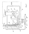
- Fig. 1 is a schematic diagram of a basic embodiment of the invention.
- Fig. 2 is a schematic diagram of an alternative embodiment of the invention.
- specific terminology will be resorted to for the sake of clarity. However, it is not intended that the invention be limited to the specific term so selected and it is to be understood that each specific term includes all technical equivalents which operate in a similar manner to accomplish a similar purpose. For example, the word connected or term similar thereto are often used. They are not limited to direct connection, but include connection through other elements where such connection is recognized as being equivalent by those skilled in the art.
- Fig. 1 is a schematic diagram of an embodiment of the invention illustrating its basic principles.
- the invention separates oxygen from air in a process that operates entirely at essentially atmospheric pressure because it uses no compressor.
- the invention outputs a mixture of the ordinary gas components found in air but the mixture is oxygen enriched, that is the proportion of oxygen is substantially greater than the proportion found in air entering the system.
- the enriched oxygen mixture is supplied at atmospheric pressure ready for use.
- an ambient air input 10 includes an ambient air inlet passage leading from an opening 12 for inputting atmosphere air, through an insulating enclosure 13, to a vessel 14 for confining gases.
- a free piston Stirling cryocooler 16 of a type well known in the art, has its cold finger 18 extending into the vessel 14 to provide a cooled surface 20. Oxygen in air that is incoming through the air input 10 is directly condensed on this cooled surface 20.
- the cryocooler 16 has a conventional temperature control system for maintaining the cold surface at a temperature greater than the boiling point temperature of nitrogen, which is 77° K at standard atmospheric pressure, and not greater than the boiling point temperature of oxygen, which is 90.1° K at standard atmospheric pressure.
- a Stirling cryocooler allows the extraction of meaningful amounts of oxygen from a small scale and portable appliance.
- the confinement vessel 14 includes a lower portion 24 for directing liquid oxygen, that drips from the cooled surface 20 by gravity, into a liquid/gas separator 26.
- the liquid/gas separator 26 may be of a type known in the art and is connected to the vessel 14 to receive liquid oxygen drained from the cooled surface 20 and separates the liquid oxygen from residual gases that remain in the vessel 14 after oxygen condensation.
- a suitable separator is the conventional trap-type of separator in which liquid flows by gravity into a receptacle which has an opening at or near its bottom followed by a trap in which the liquid collects and blocks passage of gas through the trap. Consequently, when the trap is filled, the liquid is a barrier to gas so only liquid can pass through the trap.
- the separator can be integrated with the vessel and liquid output can be directly from the vessel. The volume flow rate of air into the system and the rate of condensation should be maintained sufficient to keep the trap filled with liquid oxygen to assure that it remains a barrier to gas.
- An oxygen output 28 includes an oxygen outlet passage and is connected to the liquid output of the separator 26 for directing oxygen away from the vessel 14 to the user.
- a residual gases output 30, including a residual gas outlet passage, is connected to the gas output of the separator 26 for exhausting residual gases from the vessel at substantially atmospheric pressure.
- Incoming air and the separated gases must be moved through the system at a flow rate that is sufficient to condense a useful quantity of oxygen.
- oxygen As oxygen is condensed on the cooled surface 20, fresh oxygen must be supplied into the vessel to replenish the condensed oxygen.
- an air impeller 32 driven by an electric motor is provided in the ambient air input 10.
- An air impeller is needed in the system to move the gases through the system at a useful flow rate and therefore need only create a pressure gradient through the system that is sufficient to overcome the flow resistance of the system and provide the desired flow rate.
- the impeller can be located elsewhere in the gas flow circuit of the system, it is preferably located in the input 10 and outside of the insulating enclosure 13. Because the impeller propels the gases through a series of open passages and enclosed spaces without any small orifices or closed valves, the air is propelled at substantially atmospheric pressure thorough the ambient air inlet passage, the residual gas passage and the vessel.
- a critically important feature of the invention is the inclusion of a heat exchanger 34 because it is the principal means for recuperating energy used to condense the oxygen. Because both the oxygen flowing from the separator 26 through the oxygen output 28 and the residual gases flowing from the separator 26 through the residual gas output 30 have been cooled to temperatures far below the temperature of the ambient air, the cooling energy in these exiting gases can be used to pre-cool the air that is propelled through the ambient air input 10 into the vessel 14.
- the heat exchanger 34 is preferably a counter-flow heat exchanger having three passages separated by gas impervious, thermally conductive walls. The three heat exchanger passages are connected respectively in the ambient air input 10, the oxygen output 28 and the residual gas output 30.
- This pre-cooling and energy transfer serves not only to reduce the energy required at the cooling surface 20 to condense the oxygen, but also warms the outgoing oxygen and residual gases to near the ambient temperature. This makes the system safer and provides oxygen to the user at a temperature which is safer and more comfortable for consumption by a user.
- the controls systems typically include a cold finger temperature sensor connected in a feedback control system that controls the cooling energy delivered by the cryocooler to maintain it at a set point temperature. Since the boiling point temperature at standard pressure for O 2 is 90.1°K and for N 2 is 77°K, the cooled surface 20 must be cooled down to at least 90.1°K at standard pressure so oxygen will condense but should not be cooled down as low as 77°K so that nitrogen will not condense. Preferably, the cooled surface 20 is cooled to just below 90.1°K, such as to 87°K. This is cool enough to condense the oxygen but well above the boiling point temperature of nitrogen in order to avoid energy loss from excessive and unnecessary cooling. Thus, the invention has improved energy efficiency because the cooled surface does not need to be cooler to condense other constituents of the air.
- boiling point temperatures change with a change in pressure
- these temperatures, and particularly the set point temperature of the control system will be changed correspondingly for other ambient pressures, for example when an embodiment of the invention is operated at higher elevations.
- the temperature control system set point temperature can be adjusted to compensate for the small variation within the system from the ambient pressure.
- Embodiments of the invention can operate essentially at atmospheric pressure in comparison to prior art systems because there are no compressors, valves or orifices to maintain a higher pressure.
- the system is open to the atmosphere. Therefore, the air impeller must only develop a sufficiently large pressure gradient across it to overcome the pressure drop in the passages and along the gas flow path, parasitic losses and to obtain the volume flow rate needed to supply sufficient oxygen to a user.
- the pressure gradient across the impeller is then dropped across the system so that the gases leaving the system are at atmospheric pressure. Since most humans consume 2-3 liters of air per minute and air contains about 20% oxygen, the system would require a flow rate of approximately 10-15 liters of air per minute if the system were 100% efficient and supplied pure oxygen.
- the pressure gradient required of the impeller is a function of passage diameters and other physical properties of the flow path that affect the fluid flow.
- the invention requires an impeller pressure gradient below 1 bar and is capable of operating most effectively with a pressure gradient far below 1 bar.
- the invention operates at substantially atmospheric pressure. At no stage along the process of conversion of the oxygen from the ambient atmosphere to delivery of the oxygen rich supply to the user is any gas in the system pressurized beyond substantially atmospheric pressure.
- Water Removal Because atmospheric air entering the system is pre-cooled in the heat exchanger 34, atmospheric moisture will condense in the heat exchanger 34. Water removal from the incoming air is important, including the location in the system where it is removed. The water should be extracted and separated from the incoming air before the incoming air reaches the vessel 14. This avoids freezing and clogging of the system flow passages with ice and avoids the buildup of deposits of frozen water on the cooled surface 20. The removal of the water is illustrated diagrammatically in Fig. 1 by a water drain pipe 36 for transporting water from the system.
- the water extracted from the incoming air can be simply drained away.
- energy can also be recovered from the cold water by circulating the cold water through a heat exchanger positioned upstream of the principal heat exchange 34 to provide a preliminary pre-cooling of the incoming air.
- the water can be used to humidify the outgoing oxygen.
- the water can be disposed of by feeding it back into the outgoing residual gas stream. Feeding the water back into the residual gas stream has the advantage that there will be a greater flow volume because air is 80% nitrogen and therefore the water can be evaporated into the outgoing residual gas stream and returned to the atmosphere. Feeding at least a portion of the water back into the oxygen stream provides the advantage that it re-humidifies the oxygen making is less likely to dry out the tissues of the user.
- a cryocooler cold finger 50 extends into a vessel 54 and has a cooled surface 52.
- Incoming air is forced through an air input passage 56 by an impeller 58 and into the vessel 54.
- Oxygen condenses on the cooled surface 52 and drips into the air/liquid separator 60 and then flows out through the oxygen output passage 62.
- the oxygen is forced along its flow path by the pressure of the incoming air and its vapor pressure as it vaporizes along its output path.
- the residual gases in the vessel 54 are forced by the pressure of the incoming air out through the residual gas output passage 64.
- Water condensing in the portion of the ambient air input passage 56 that extends through the heat exchanger 66 flows by gravity down through a liquid/gas separator comprising a water outlet 68 and a gas trap 70 and then flows into a water jacket 72, or other heat exchanger, that is in thermal conductive connection to the ambient air input passage 56. This water preliminarily pre-cools the incoming ambient air.
- Other heat exchanger configuration can utilize other water draining configurations. The water should exit through an outlet in or below the heat exchanger where the temperature is optimal for collection and drainage of the water.
- Water collected in the water jacket 72 can be used or disposed of in one or more of a variety of ways as described above. Some or all of the water in the water jacket 72 can be drained through a drain outlet 74. Water or water vapor can be directed or pumped through a passage or conduit 76 to the outlet end 78 of the residual gas output passage 64 and/or to the outlet end 80 of the oxygen output passage 62. This can be accomplished by using the apparatus and methods known in the art for humidifying a gas, such as passing the gas over a pan of the water or through a water-soaked, fibrous matrix similar to a filter. Alternatively, the water from the water jacket 72 can be directly evaporated to the atmosphere.
- the water condensed in the ambient air input passage 56 may freeze in or near that heat exchanger, accumulate ice and block the passage.
- the temperature of the output passage in this vicinity can be controlled by one or more of: (1) adjustment of the cooling energy supplied by the Stirling cryocooler; (2) a dedicated heater using a temperature sensor and a temperature control system; and (3) using heat rejected from the Stirling cryocooler.
- Fig. 2 illustrates a temperature control 82 having a temperature input sensor 84 and connected to control a heater 86, such as an electrically heated resistive strip.
- the control has a set point temperature slightly above the freezing temperature of water to assure that no water can freeze in the ambient air input passage 56.
- the water drain outlet may be located at an intermediate position along the flow path within the heat exchanger. Because there will be a temperature gradient from one end of the heat exchanger to the opposite end, the temperature along the flow path through the heat exchanger can be measured and the drain located where the temperature is slightly above the freezing temperature of water under normal, steady state operation of an embodiment of the invention. As a consequence, not much heat energy will need to be applied to prevent freezing of the water.
- Embodiments of the invention operate by cooling a surface within a confinement vessel to a temperature greater than the boiling point temperature of nitrogen and not greater than the boiling point temperature of oxygen. Air is impelled from the atmosphere into the vessel, against the cooled surface and the air components are impelled out of the vessel, all at substantially atmospheric pressure. Oxygen droplets that condense on and drop from the cooled surface are separated from the residual gases in the vessel. The incoming air is cooled and water is condensed from it by transferring heat from the incoming air to the gases flowing outwardly from the vessel.
- the departing oxygen will be oxygen rich but not pure oxygen. Some oxygen would still be in the departing residual gases, mostly nitrogen, along with the other constituent gases in air. Furthermore, some nitrogen and other constituent gases will be mixed with the oxygen. It is not necessary that the trap of the liquid/gas separator always be filled to provide a barrier to the residual gases.
- the purpose of the invention is not to provide pure oxygen but rather is to provide an oxygen rich mixture that can be consumed by humans. Because energy is not wasted on compression of any gases, it is not necessary that even a high proportion of the oxygen be condensed.
- the oxygen output passage desirably has an adequate combination of length and rise above the liquid level in the separator. This can be determined from experimentation and the knowledge of a person of ordinary skill in the art.
- the liquid oxygen can be drained into tanks for storage.
- the advantages of the present invention arise from the combination of separation of oxygen by condensation upon a cooled surface, operating it at substantially atmospheric pressure and recovering the energy from the outgoing constituents of air that entered the system.
- the use of a Stirling cryocooler is particularly advantageous because they are small, lightweight and energy efficient.
- the most significant advantage of the invention is its small scale.
- the invention neither has nor requires a compressor or concentrator unlike the prior art which requires a compressor or concentrator before separation as a means of moving the gases through the prior art process.
- the invention has no evaporator or expansion valve and does not use an expensive separator such as a membrane separator.
- the prior art systems for oxygen separation are generally associated with large scale commercial systems intended to separate components of air for resale as compressed or liquid single component gases of various purity levels.
- the liquefying means for these large scale systems is generally a turboexpander. Stirling coolers are not used for these prior art systems because they do not scale to sizes that would support a commercial gas sales operation.
- Embodiments of the invention are small enough to be portable.
- the portability can be on two levels.
- the first level is that the unit is small enough to move around from place to place but still rely on an electrical wall outlet for input power.
- Prior art units which are intended for personal use still require a compressor or concentrator and such devices add a very significant weight to the unit.
- Prior art personal oxygen supplies require a tank which heavy and difficult to transport by an individual.
- the second level of portability is true portability, whereby the oxygen extractor is powered by a battery, and so is fully mobile and capable of being carried by a person while being used and eliminates the need to carry a tank.
- a very small pressure is required to propel the air and gases through embodiments of the invention.
- the invention requires only a sufficient flow of air to keep a fresh supply of air entering the system to attain the desired rate of oxygen production. For this, a small fan is all that is needed for the impeller.
- other low pressure, high volume air impelling devices can be used, such as a bellows or diaphragm type of pump.
- Embodiments of the invention can operate at low atmospheric pressure, such as occur at high elevations, because of the temperature control.
- the temperature control is simply adjusted to compensate for the change in the boiling point temperatures that result from changes in ambient atmospheric pressure.
- the heat exchanger allows the heat of incoming air to be extracted by outgoing, cold, separated air constituents.
- the invention recuperates very nearly all the heat extracted from the air in the separation process.
- the prior art discards energy in the form of retaining the desired gas in liquid form or releasing unwanted portions of the input gas(es) to the atmosphere in a cold state, without recuperating the heat removed.
- counter flow heat exchangers are known in the prior art in other machines, the counter-flow heat exchanger is a very important component of the present invention.
- the gases leaving the system both O 2 and N 2 (along with other constituents of air), would be at room temperature so all the heat entering the system in the incoming air would be removed by the exiting gases, i.e.
- cryocooler the cooling required by the cryocooler is minimized and limited to removing heat from inefficiencies such as radiation and conduction through surrounding insulation, the inefficiency of the recovery of the thermal energy, the work to push gas through system, and losses in the cryocooler.
Landscapes
- Engineering & Computer Science (AREA)
- Physics & Mathematics (AREA)
- Mechanical Engineering (AREA)
- Thermal Sciences (AREA)
- General Engineering & Computer Science (AREA)
- Health & Medical Sciences (AREA)
- Emergency Medicine (AREA)
- Heart & Thoracic Surgery (AREA)
- General Health & Medical Sciences (AREA)
- Biomedical Technology (AREA)
- Pulmonology (AREA)
- Hematology (AREA)
- Life Sciences & Earth Sciences (AREA)
- Animal Behavior & Ethology (AREA)
- Anesthesiology (AREA)
- Public Health (AREA)
- Veterinary Medicine (AREA)
- Separation By Low-Temperature Treatments (AREA)
- Oxygen, Ozone, And Oxides In General (AREA)
- Physical Or Chemical Processes And Apparatus (AREA)
- Road Repair (AREA)
- Heat-Exchange Devices With Radiators And Conduit Assemblies (AREA)
Applications Claiming Priority (2)
| Application Number | Priority Date | Filing Date | Title |
|---|---|---|---|
| US10/910,401 US7210312B2 (en) | 2004-08-03 | 2004-08-03 | Energy efficient, inexpensive extraction of oxygen from ambient air for portable and home use |
| EP05758037A EP1782009B1 (de) | 2004-08-03 | 2005-06-08 | Energiesparende, preisgünstige gewinnung von sauerstoff aus umgebungsluft für den einsatz unterwegs und zuhause |
Related Parent Applications (2)
| Application Number | Title | Priority Date | Filing Date |
|---|---|---|---|
| EP05758037A Division EP1782009B1 (de) | 2004-08-03 | 2005-06-08 | Energiesparende, preisgünstige gewinnung von sauerstoff aus umgebungsluft für den einsatz unterwegs und zuhause |
| EP05758037.5 Division | 2005-06-08 |
Publications (1)
| Publication Number | Publication Date |
|---|---|
| EP2154458A2 true EP2154458A2 (de) | 2010-02-17 |
Family
ID=35756059
Family Applications (2)
| Application Number | Title | Priority Date | Filing Date |
|---|---|---|---|
| EP09176935A Withdrawn EP2154458A2 (de) | 2004-08-03 | 2005-06-08 | Energieeffiziente, kostengünstige Extraktion von Sauerstoff aus der Umgebungsluft für tragbare Geräte und den Hausgebrauch |
| EP05758037A Expired - Lifetime EP1782009B1 (de) | 2004-08-03 | 2005-06-08 | Energiesparende, preisgünstige gewinnung von sauerstoff aus umgebungsluft für den einsatz unterwegs und zuhause |
Family Applications After (1)
| Application Number | Title | Priority Date | Filing Date |
|---|---|---|---|
| EP05758037A Expired - Lifetime EP1782009B1 (de) | 2004-08-03 | 2005-06-08 | Energiesparende, preisgünstige gewinnung von sauerstoff aus umgebungsluft für den einsatz unterwegs und zuhause |
Country Status (11)
| Country | Link |
|---|---|
| US (1) | US7210312B2 (de) |
| EP (2) | EP2154458A2 (de) |
| JP (1) | JP2008509372A (de) |
| KR (1) | KR100859387B1 (de) |
| CN (1) | CN101027527A (de) |
| AT (1) | ATE454600T1 (de) |
| BR (1) | BRPI0514075A (de) |
| CA (1) | CA2578241C (de) |
| DE (1) | DE602005018792D1 (de) |
| NZ (1) | NZ552512A (de) |
| WO (1) | WO2006022975A2 (de) |
Families Citing this family (23)
| Publication number | Priority date | Publication date | Assignee | Title |
|---|---|---|---|---|
| US20050274142A1 (en) * | 2004-06-14 | 2005-12-15 | Corey John A | Cryogenically producing oxygen-enriched liquid and/or gaseous oxygen from atmospheric air |
| US7213400B2 (en) * | 2004-10-26 | 2007-05-08 | Respironics In-X, Inc. | Liquefying and storing a gas |
| ES2625284T5 (es) * | 2006-02-27 | 2023-12-01 | Highview Entpr Ltd | Método de almacenamiento de energía y sistema de almacenamiento de energía criogénica |
| US8308446B2 (en) * | 2007-04-06 | 2012-11-13 | Quincy Compressor Llc | Smart blow-down system for variable frequency drive compressor units |
| JP4786591B2 (ja) * | 2007-05-11 | 2011-10-05 | オリオン機械株式会社 | Voc冷却回収装置 |
| FR2946735B1 (fr) * | 2009-06-12 | 2012-07-13 | Air Liquide | Appareil et procede de separation d'air par distillation cryogenique. |
| US8371073B2 (en) * | 2010-03-04 | 2013-02-12 | Michael Fuller Architects, Pc | Building with integrated natural systems |
| US20110283737A1 (en) * | 2010-05-20 | 2011-11-24 | Siemens Medical Solutions Usa, Inc. | Process for separating gases at cryogenic temperatures |
| CN102564066B (zh) * | 2012-02-10 | 2013-10-16 | 南京柯德超低温技术有限公司 | 基于小型低温制冷机的用于气体分离和纯化的低温装置 |
| CN104963784B (zh) * | 2015-07-10 | 2016-09-07 | 宁波江东波莫纳电子科技有限公司 | 一种基于反复活塞供热的斯特林发动机 |
| WO2017105191A1 (es) * | 2015-12-16 | 2017-06-22 | Velez De La Rocha Martin | Proceso de separación de aire |
| WO2017105193A1 (es) * | 2015-12-16 | 2017-06-22 | Velez De La Rocha Martin | Sistema de licuefaccion de gases por condensacion flash, enfriador criogenico e intercambiador de calor de placa y aleta tipo bahx |
| CN105605419B (zh) * | 2015-12-31 | 2018-08-07 | 杰瑞石油天然气工程有限公司 | 空氮站冷能综合回收利用系统及其回收利用方法 |
| GB201601878D0 (en) | 2016-02-02 | 2016-03-16 | Highview Entpr Ltd | Improvements in power recovery |
| DE102016012676A1 (de) | 2016-04-22 | 2017-10-26 | Holger Kleim | Cryo/sol = habitat, anwendung eines verbundes aus anlagenkomplexen mit ferfahren zur autarken erzeugung von stoffen |
| US11305879B2 (en) | 2018-03-23 | 2022-04-19 | Raytheon Technologies Corporation | Propulsion system cooling control |
| CN113446789B (zh) * | 2020-03-24 | 2022-09-16 | 合肥华凌股份有限公司 | 除氧组件、储物装置及冰箱 |
| US11692508B2 (en) * | 2020-08-04 | 2023-07-04 | The Government Of The United States Of America, As Represented By The Secretary Of The Navy | Dual stirling cycle liquid air battery |
| IL276649B2 (en) * | 2020-08-11 | 2025-11-01 | Sodastream Ind Ltd | Respiratory machine |
| EP4237773A4 (de) * | 2020-10-27 | 2024-10-09 | Fabrum IP Holdings Limited | Luftbehandlungssystem und verfahren zur luftbehandlung |
| US11448459B1 (en) * | 2021-07-23 | 2022-09-20 | The Tisdale Group, LLC | Cryogenic gas separator |
| KR102910301B1 (ko) * | 2022-11-10 | 2026-01-09 | 주식회사 패리티 | 증류시스템의 극저온 재액화장치 |
| CN116817541B (zh) * | 2023-08-31 | 2023-11-10 | 齐齐哈尔黎明气体有限公司 | 医用氧充装过程放空气体回收装置 |
Citations (2)
| Publication number | Priority date | Publication date | Assignee | Title |
|---|---|---|---|---|
| US5704227A (en) | 1995-04-11 | 1998-01-06 | Krabbendam; Peter Jozef | Method of condensing a volatile compound out of a gas stream and an apparatus for this purpose |
| US5893275A (en) | 1997-09-04 | 1999-04-13 | In-X Corporation | Compact small volume liquid oxygen production system |
Family Cites Families (34)
| Publication number | Priority date | Publication date | Assignee | Title |
|---|---|---|---|---|
| WO1982001242A1 (en) * | 1980-09-25 | 1982-04-15 | A Suslov | Method and installation for obtaining nitrogen and oxygen |
| GB8407857D0 (en) * | 1984-03-27 | 1984-05-02 | Mann R | Separation of gaseous mixture |
| JPS6124967A (ja) * | 1984-07-13 | 1986-02-03 | 大同酸素株式会社 | 高純度窒素ガス製造装置 |
| JPS6124968A (ja) * | 1984-07-13 | 1986-02-03 | 大同酸素株式会社 | 高純度窒素ガス製造装置 |
| JPS61190277A (ja) * | 1985-02-16 | 1986-08-23 | 大同酸素株式会社 | 高純度窒素および酸素ガス製造装置 |
| JPS62162584U (de) * | 1986-04-03 | 1987-10-15 | ||
| JPH02187126A (ja) * | 1989-01-13 | 1990-07-23 | Sumitomo Heavy Ind Ltd | 圧力変動吸着法に於ける原料ガスの除湿方法とその装置 |
| JPH02116691U (de) * | 1989-03-01 | 1990-09-18 | ||
| JPH02254283A (ja) * | 1989-03-28 | 1990-10-15 | Mitsubishi Electric Corp | 酸素濃縮装置 |
| US5148680A (en) * | 1990-06-27 | 1992-09-22 | Union Carbide Industrial Gases Technology Corporation | Cryogenic air separation system with dual product side condenser |
| US5305610A (en) * | 1990-08-28 | 1994-04-26 | Air Products And Chemicals, Inc. | Process and apparatus for producing nitrogen and oxygen |
| JPH0453422U (de) * | 1990-09-12 | 1992-05-07 | ||
| GB9021435D0 (en) * | 1990-10-02 | 1990-11-14 | Boc Group Plc | Separation of gas mixtures |
| FR2681416B1 (fr) * | 1991-09-13 | 1993-11-19 | Air Liquide | Procede de refroidissement d'un gaz dans une installation d'exploitation de gaz de l'air, et installation. |
| US5410885A (en) * | 1993-08-09 | 1995-05-02 | Smolarek; James | Cryogenic rectification system for lower pressure operation |
| GB9503592D0 (en) * | 1995-02-23 | 1995-04-12 | Boc Group Plc | Separation of gas mixtures |
| US5590543A (en) * | 1995-08-29 | 1997-01-07 | Air Products And Chemicals, Inc. | Production of ultra-high purity oxygen from cryogenic air separation plants |
| US5592832A (en) * | 1995-10-03 | 1997-01-14 | Air Products And Chemicals, Inc. | Process and apparatus for the production of moderate purity oxygen |
| JPH09108527A (ja) * | 1995-10-16 | 1997-04-28 | Masayuki Imai | 濃縮酸素供給方法及び装置 |
| US5644932A (en) | 1996-05-21 | 1997-07-08 | Air Products And Chemicals, Inc. | Use of structured packing in a multi-sectioned air seperation unit |
| DE19631949C2 (de) * | 1996-08-08 | 1998-09-03 | Druckluft Dannoehl Gmbh | Verfahren und Vorrichtung zum Erzeugen von Stickstoff aus Luft |
| JPH10170144A (ja) * | 1996-12-10 | 1998-06-26 | Nippon Sanso Kk | 空気液化分離装置の原料空気精製装置及び方法 |
| US5730003A (en) * | 1997-03-26 | 1998-03-24 | Praxair Technology, Inc. | Cryogenic hybrid system for producing high purity argon |
| US5979440A (en) * | 1997-06-16 | 1999-11-09 | Sequal Technologies, Inc. | Methods and apparatus to generate liquid ambulatory oxygen from an oxygen concentrator |
| US6044902A (en) | 1997-08-20 | 2000-04-04 | Praxair Technology, Inc. | Heat exchange unit for a cryogenic air separation system |
| US5996373A (en) * | 1998-02-04 | 1999-12-07 | L'air Liquide, Societe Ananyme Pour L'etude Et L'exploitation Des Procedes Georges Claude | Cryogenic air separation process and apparatus |
| US20010004838A1 (en) | 1999-10-29 | 2001-06-28 | Wong Kenneth Kai | Integrated heat exchanger system for producing carbon dioxide |
| US6212904B1 (en) * | 1999-11-01 | 2001-04-10 | In-X Corporation | Liquid oxygen production |
| US6383257B1 (en) | 2000-04-04 | 2002-05-07 | Air Products And Chemicals, Inc. | Reclamation and separation of perfluorocarbons using condensation |
| US6279345B1 (en) | 2000-05-18 | 2001-08-28 | Praxair Technology, Inc. | Cryogenic air separation system with split kettle recycle |
| JP3547121B2 (ja) * | 2000-05-31 | 2004-07-28 | 大陽東洋酸素株式会社 | 医療用酸素濃縮器 |
| US6357259B1 (en) | 2000-09-29 | 2002-03-19 | The Boc Group, Inc. | Air separation method to produce gaseous product |
| JP3726965B2 (ja) * | 2002-07-01 | 2005-12-14 | 富士電機システムズ株式会社 | 酸素の製造方法と装置 |
| US20050274142A1 (en) * | 2004-06-14 | 2005-12-15 | Corey John A | Cryogenically producing oxygen-enriched liquid and/or gaseous oxygen from atmospheric air |
-
2004
- 2004-08-03 US US10/910,401 patent/US7210312B2/en not_active Expired - Fee Related
-
2005
- 2005-06-08 JP JP2007524797A patent/JP2008509372A/ja active Pending
- 2005-06-08 NZ NZ552512A patent/NZ552512A/en unknown
- 2005-06-08 CN CNA2005800323435A patent/CN101027527A/zh active Pending
- 2005-06-08 CA CA002578241A patent/CA2578241C/en not_active Expired - Fee Related
- 2005-06-08 EP EP09176935A patent/EP2154458A2/de not_active Withdrawn
- 2005-06-08 BR BRPI0514075-7A patent/BRPI0514075A/pt not_active IP Right Cessation
- 2005-06-08 AT AT05758037T patent/ATE454600T1/de not_active IP Right Cessation
- 2005-06-08 EP EP05758037A patent/EP1782009B1/de not_active Expired - Lifetime
- 2005-06-08 KR KR1020077004860A patent/KR100859387B1/ko not_active Expired - Fee Related
- 2005-06-08 WO PCT/US2005/019928 patent/WO2006022975A2/en not_active Ceased
- 2005-06-08 DE DE602005018792T patent/DE602005018792D1/de not_active Expired - Fee Related
Patent Citations (2)
| Publication number | Priority date | Publication date | Assignee | Title |
|---|---|---|---|---|
| US5704227A (en) | 1995-04-11 | 1998-01-06 | Krabbendam; Peter Jozef | Method of condensing a volatile compound out of a gas stream and an apparatus for this purpose |
| US5893275A (en) | 1997-09-04 | 1999-04-13 | In-X Corporation | Compact small volume liquid oxygen production system |
Also Published As
| Publication number | Publication date |
|---|---|
| KR100859387B1 (ko) | 2008-09-22 |
| DE602005018792D1 (de) | 2010-02-25 |
| EP1782009A4 (de) | 2008-02-20 |
| US7210312B2 (en) | 2007-05-01 |
| WO2006022975A2 (en) | 2006-03-02 |
| WO2006022975A3 (en) | 2006-11-30 |
| NZ552512A (en) | 2010-03-26 |
| US20060026988A1 (en) | 2006-02-09 |
| BRPI0514075A (pt) | 2008-05-27 |
| EP1782009A2 (de) | 2007-05-09 |
| EP1782009B1 (de) | 2010-01-06 |
| KR20070040407A (ko) | 2007-04-16 |
| CA2578241A1 (en) | 2006-03-02 |
| CN101027527A (zh) | 2007-08-29 |
| JP2008509372A (ja) | 2008-03-27 |
| CA2578241C (en) | 2009-11-03 |
| ATE454600T1 (de) | 2010-01-15 |
Similar Documents
| Publication | Publication Date | Title |
|---|---|---|
| US7210312B2 (en) | Energy efficient, inexpensive extraction of oxygen from ambient air for portable and home use | |
| JP2003515086A (ja) | 液体酸素の生成 | |
| JP4183760B2 (ja) | 酸素濃縮装置から携帯用液体酸素を生成する装置 | |
| US5893275A (en) | Compact small volume liquid oxygen production system | |
| JP5143563B2 (ja) | 小型ガス液化装置 | |
| EP0207230B1 (de) | Kryopumpe für Wasserdampf mit schnell umschaltbarem Kreislauf | |
| US20050274142A1 (en) | Cryogenically producing oxygen-enriched liquid and/or gaseous oxygen from atmospheric air | |
| TW200923300A (en) | System to cold compress an air stream using natural gas refrigeration | |
| US7121116B2 (en) | Method and device for producing oxygen | |
| US7644594B2 (en) | Method and apparatus for self-contained anesthetic gas reclamation | |
| US4535597A (en) | Fast cycle water vapor cryopump | |
| JP5460716B2 (ja) | 携帯型使用のための液体酸素を生成するためのシステムおよび方法 | |
| BRPI0808718B1 (pt) | Unidade de resfriamento e de aquecimento de vazões | |
| AU644962B2 (en) | Air separation method for supplying gaseous oxygen in accordance with a variable demand pattern | |
| US20110185766A1 (en) | Refrigerator, and Method for Producing Very Low Temperature Cold | |
| CN101212998B (zh) | 麻醉气体回收方法及装置 | |
| RU2415681C2 (ru) | Аппарат и способ для переработки анестезирующего газа | |
| HK1104346A (en) | Energy efficient, inexpensive extraction of oxygen from ambient air for portable and home use | |
| JP2023138414A (ja) | 二酸化炭素回収装置 | |
| JPH11244643A (ja) | 絶縁ガス回収充填装置 | |
| Dauvergne et al. | A helium freeze-out cleaner operating at atmospheric pressure | |
| JP3191161B2 (ja) | 液化天然ガスの寒冷を利用した空気液化分離装置の冷却水冷却方法及び装置 | |
| JP2003526065A (ja) | 相転移無熱冷却方法および装置 | |
| CN117342000A (zh) | 用于大型环模设备的大气量多级空气复压系统及方法 |
Legal Events
| Date | Code | Title | Description |
|---|---|---|---|
| PUAI | Public reference made under article 153(3) epc to a published international application that has entered the european phase |
Free format text: ORIGINAL CODE: 0009012 |
|
| AC | Divisional application: reference to earlier application |
Ref document number: 1782009 Country of ref document: EP Kind code of ref document: P |
|
| AK | Designated contracting states |
Kind code of ref document: A2 Designated state(s): AT BE BG CH CY CZ DE DK EE ES FI FR GB GR HU IE IS IT LI LT LU MC NL PL PT RO SE SI SK TR |
|
| STAA | Information on the status of an ep patent application or granted ep patent |
Free format text: STATUS: THE APPLICATION IS DEEMED TO BE WITHDRAWN |
|
| 18D | Application deemed to be withdrawn |
Effective date: 20110104 |