EP2151586A2 - Circuit hydraulique - Google Patents
Circuit hydraulique Download PDFInfo
- Publication number
- EP2151586A2 EP2151586A2 EP09008112A EP09008112A EP2151586A2 EP 2151586 A2 EP2151586 A2 EP 2151586A2 EP 09008112 A EP09008112 A EP 09008112A EP 09008112 A EP09008112 A EP 09008112A EP 2151586 A2 EP2151586 A2 EP 2151586A2
- Authority
- EP
- European Patent Office
- Prior art keywords
- pressure
- hydraulic circuit
- leakage
- working
- valve
- Prior art date
- Legal status (The legal status is an assumption and is not a legal conclusion. Google has not performed a legal analysis and makes no representation as to the accuracy of the status listed.)
- Withdrawn
Links
Images


Classifications
-
- F—MECHANICAL ENGINEERING; LIGHTING; HEATING; WEAPONS; BLASTING
- F16—ENGINEERING ELEMENTS AND UNITS; GENERAL MEASURES FOR PRODUCING AND MAINTAINING EFFECTIVE FUNCTIONING OF MACHINES OR INSTALLATIONS; THERMAL INSULATION IN GENERAL
- F16D—COUPLINGS FOR TRANSMITTING ROTATION; CLUTCHES; BRAKES
- F16D48/00—External control of clutches
- F16D48/02—Control by fluid pressure
- F16D48/0206—Control by fluid pressure in a system with a plurality of fluid-actuated clutches
-
- F—MECHANICAL ENGINEERING; LIGHTING; HEATING; WEAPONS; BLASTING
- F15—FLUID-PRESSURE ACTUATORS; HYDRAULICS OR PNEUMATICS IN GENERAL
- F15B—SYSTEMS ACTING BY MEANS OF FLUIDS IN GENERAL; FLUID-PRESSURE ACTUATORS, e.g. SERVOMOTORS; DETAILS OF FLUID-PRESSURE SYSTEMS, NOT OTHERWISE PROVIDED FOR
- F15B11/00—Servomotor systems without provision for follow-up action; Circuits therefor
- F15B11/02—Systems essentially incorporating special features for controlling the speed or actuating force of an output member
-
- F—MECHANICAL ENGINEERING; LIGHTING; HEATING; WEAPONS; BLASTING
- F16—ENGINEERING ELEMENTS AND UNITS; GENERAL MEASURES FOR PRODUCING AND MAINTAINING EFFECTIVE FUNCTIONING OF MACHINES OR INSTALLATIONS; THERMAL INSULATION IN GENERAL
- F16H—GEARING
- F16H61/00—Control functions within control units of change-speed- or reversing-gearings for conveying rotary motion ; Control of exclusively fluid gearing, friction gearing, gearings with endless flexible members or other particular types of gearing
- F16H61/02—Control functions within control units of change-speed- or reversing-gearings for conveying rotary motion ; Control of exclusively fluid gearing, friction gearing, gearings with endless flexible members or other particular types of gearing characterised by the signals used
- F16H61/0202—Control functions within control units of change-speed- or reversing-gearings for conveying rotary motion ; Control of exclusively fluid gearing, friction gearing, gearings with endless flexible members or other particular types of gearing characterised by the signals used the signals being electric
- F16H61/0204—Control functions within control units of change-speed- or reversing-gearings for conveying rotary motion ; Control of exclusively fluid gearing, friction gearing, gearings with endless flexible members or other particular types of gearing characterised by the signals used the signals being electric for gearshift control, e.g. control functions for performing shifting or generation of shift signal
- F16H61/0206—Layout of electro-hydraulic control circuits, e.g. arrangement of valves
-
- F—MECHANICAL ENGINEERING; LIGHTING; HEATING; WEAPONS; BLASTING
- F15—FLUID-PRESSURE ACTUATORS; HYDRAULICS OR PNEUMATICS IN GENERAL
- F15B—SYSTEMS ACTING BY MEANS OF FLUIDS IN GENERAL; FLUID-PRESSURE ACTUATORS, e.g. SERVOMOTORS; DETAILS OF FLUID-PRESSURE SYSTEMS, NOT OTHERWISE PROVIDED FOR
- F15B2211/00—Circuits for servomotor systems
- F15B2211/20—Fluid pressure source, e.g. accumulator or variable axial piston pump
- F15B2211/205—Systems with pumps
- F15B2211/20507—Type of prime mover
- F15B2211/20515—Electric motor
-
- F—MECHANICAL ENGINEERING; LIGHTING; HEATING; WEAPONS; BLASTING
- F15—FLUID-PRESSURE ACTUATORS; HYDRAULICS OR PNEUMATICS IN GENERAL
- F15B—SYSTEMS ACTING BY MEANS OF FLUIDS IN GENERAL; FLUID-PRESSURE ACTUATORS, e.g. SERVOMOTORS; DETAILS OF FLUID-PRESSURE SYSTEMS, NOT OTHERWISE PROVIDED FOR
- F15B2211/00—Circuits for servomotor systems
- F15B2211/30—Directional control
- F15B2211/305—Directional control characterised by the type of valves
- F15B2211/30505—Non-return valves, i.e. check valves
-
- F—MECHANICAL ENGINEERING; LIGHTING; HEATING; WEAPONS; BLASTING
- F15—FLUID-PRESSURE ACTUATORS; HYDRAULICS OR PNEUMATICS IN GENERAL
- F15B—SYSTEMS ACTING BY MEANS OF FLUIDS IN GENERAL; FLUID-PRESSURE ACTUATORS, e.g. SERVOMOTORS; DETAILS OF FLUID-PRESSURE SYSTEMS, NOT OTHERWISE PROVIDED FOR
- F15B2211/00—Circuits for servomotor systems
- F15B2211/30—Directional control
- F15B2211/305—Directional control characterised by the type of valves
- F15B2211/3056—Assemblies of multiple valves
- F15B2211/30565—Assemblies of multiple valves having multiple valves for a single output member, e.g. for creating higher valve function by use of multiple valves like two 2/2-valves replacing a 5/3-valve
- F15B2211/30575—Assemblies of multiple valves having multiple valves for a single output member, e.g. for creating higher valve function by use of multiple valves like two 2/2-valves replacing a 5/3-valve in a Wheatstone Bridge arrangement (also half bridges)
-
- F—MECHANICAL ENGINEERING; LIGHTING; HEATING; WEAPONS; BLASTING
- F15—FLUID-PRESSURE ACTUATORS; HYDRAULICS OR PNEUMATICS IN GENERAL
- F15B—SYSTEMS ACTING BY MEANS OF FLUIDS IN GENERAL; FLUID-PRESSURE ACTUATORS, e.g. SERVOMOTORS; DETAILS OF FLUID-PRESSURE SYSTEMS, NOT OTHERWISE PROVIDED FOR
- F15B2211/00—Circuits for servomotor systems
- F15B2211/30—Directional control
- F15B2211/315—Directional control characterised by the connections of the valve or valves in the circuit
- F15B2211/3157—Directional control characterised by the connections of the valve or valves in the circuit being connected to a pressure source, an output member and a return line
- F15B2211/31576—Directional control characterised by the connections of the valve or valves in the circuit being connected to a pressure source, an output member and a return line having a single pressure source and a single output member
-
- F—MECHANICAL ENGINEERING; LIGHTING; HEATING; WEAPONS; BLASTING
- F15—FLUID-PRESSURE ACTUATORS; HYDRAULICS OR PNEUMATICS IN GENERAL
- F15B—SYSTEMS ACTING BY MEANS OF FLUIDS IN GENERAL; FLUID-PRESSURE ACTUATORS, e.g. SERVOMOTORS; DETAILS OF FLUID-PRESSURE SYSTEMS, NOT OTHERWISE PROVIDED FOR
- F15B2211/00—Circuits for servomotor systems
- F15B2211/30—Directional control
- F15B2211/32—Directional control characterised by the type of actuation
- F15B2211/327—Directional control characterised by the type of actuation electrically or electronically
-
- F—MECHANICAL ENGINEERING; LIGHTING; HEATING; WEAPONS; BLASTING
- F15—FLUID-PRESSURE ACTUATORS; HYDRAULICS OR PNEUMATICS IN GENERAL
- F15B—SYSTEMS ACTING BY MEANS OF FLUIDS IN GENERAL; FLUID-PRESSURE ACTUATORS, e.g. SERVOMOTORS; DETAILS OF FLUID-PRESSURE SYSTEMS, NOT OTHERWISE PROVIDED FOR
- F15B2211/00—Circuits for servomotor systems
- F15B2211/40—Flow control
- F15B2211/415—Flow control characterised by the connections of the flow control means in the circuit
- F15B2211/41581—Flow control characterised by the connections of the flow control means in the circuit being connected to an output member and a return line
-
- F—MECHANICAL ENGINEERING; LIGHTING; HEATING; WEAPONS; BLASTING
- F15—FLUID-PRESSURE ACTUATORS; HYDRAULICS OR PNEUMATICS IN GENERAL
- F15B—SYSTEMS ACTING BY MEANS OF FLUIDS IN GENERAL; FLUID-PRESSURE ACTUATORS, e.g. SERVOMOTORS; DETAILS OF FLUID-PRESSURE SYSTEMS, NOT OTHERWISE PROVIDED FOR
- F15B2211/00—Circuits for servomotor systems
- F15B2211/40—Flow control
- F15B2211/42—Flow control characterised by the type of actuation
- F15B2211/426—Flow control characterised by the type of actuation electrically or electronically
-
- F—MECHANICAL ENGINEERING; LIGHTING; HEATING; WEAPONS; BLASTING
- F15—FLUID-PRESSURE ACTUATORS; HYDRAULICS OR PNEUMATICS IN GENERAL
- F15B—SYSTEMS ACTING BY MEANS OF FLUIDS IN GENERAL; FLUID-PRESSURE ACTUATORS, e.g. SERVOMOTORS; DETAILS OF FLUID-PRESSURE SYSTEMS, NOT OTHERWISE PROVIDED FOR
- F15B2211/00—Circuits for servomotor systems
- F15B2211/40—Flow control
- F15B2211/45—Control of bleed-off flow, e.g. control of bypass flow to the return line
-
- F—MECHANICAL ENGINEERING; LIGHTING; HEATING; WEAPONS; BLASTING
- F15—FLUID-PRESSURE ACTUATORS; HYDRAULICS OR PNEUMATICS IN GENERAL
- F15B—SYSTEMS ACTING BY MEANS OF FLUIDS IN GENERAL; FLUID-PRESSURE ACTUATORS, e.g. SERVOMOTORS; DETAILS OF FLUID-PRESSURE SYSTEMS, NOT OTHERWISE PROVIDED FOR
- F15B2211/00—Circuits for servomotor systems
- F15B2211/60—Circuit components or control therefor
- F15B2211/625—Accumulators
-
- F—MECHANICAL ENGINEERING; LIGHTING; HEATING; WEAPONS; BLASTING
- F15—FLUID-PRESSURE ACTUATORS; HYDRAULICS OR PNEUMATICS IN GENERAL
- F15B—SYSTEMS ACTING BY MEANS OF FLUIDS IN GENERAL; FLUID-PRESSURE ACTUATORS, e.g. SERVOMOTORS; DETAILS OF FLUID-PRESSURE SYSTEMS, NOT OTHERWISE PROVIDED FOR
- F15B2211/00—Circuits for servomotor systems
- F15B2211/60—Circuit components or control therefor
- F15B2211/63—Electronic controllers
- F15B2211/6303—Electronic controllers using input signals
- F15B2211/6306—Electronic controllers using input signals representing a pressure
- F15B2211/6309—Electronic controllers using input signals representing a pressure the pressure being a pressure source supply pressure
-
- F—MECHANICAL ENGINEERING; LIGHTING; HEATING; WEAPONS; BLASTING
- F15—FLUID-PRESSURE ACTUATORS; HYDRAULICS OR PNEUMATICS IN GENERAL
- F15B—SYSTEMS ACTING BY MEANS OF FLUIDS IN GENERAL; FLUID-PRESSURE ACTUATORS, e.g. SERVOMOTORS; DETAILS OF FLUID-PRESSURE SYSTEMS, NOT OTHERWISE PROVIDED FOR
- F15B2211/00—Circuits for servomotor systems
- F15B2211/60—Circuit components or control therefor
- F15B2211/63—Electronic controllers
- F15B2211/6303—Electronic controllers using input signals
- F15B2211/6306—Electronic controllers using input signals representing a pressure
- F15B2211/6313—Electronic controllers using input signals representing a pressure the pressure being a load pressure
-
- F—MECHANICAL ENGINEERING; LIGHTING; HEATING; WEAPONS; BLASTING
- F15—FLUID-PRESSURE ACTUATORS; HYDRAULICS OR PNEUMATICS IN GENERAL
- F15B—SYSTEMS ACTING BY MEANS OF FLUIDS IN GENERAL; FLUID-PRESSURE ACTUATORS, e.g. SERVOMOTORS; DETAILS OF FLUID-PRESSURE SYSTEMS, NOT OTHERWISE PROVIDED FOR
- F15B2211/00—Circuits for servomotor systems
- F15B2211/70—Output members, e.g. hydraulic motors or cylinders or control therefor
- F15B2211/705—Output members, e.g. hydraulic motors or cylinders or control therefor characterised by the type of output members or actuators
- F15B2211/7051—Linear output members
- F15B2211/7052—Single-acting output members
-
- F—MECHANICAL ENGINEERING; LIGHTING; HEATING; WEAPONS; BLASTING
- F16—ENGINEERING ELEMENTS AND UNITS; GENERAL MEASURES FOR PRODUCING AND MAINTAINING EFFECTIVE FUNCTIONING OF MACHINES OR INSTALLATIONS; THERMAL INSULATION IN GENERAL
- F16D—COUPLINGS FOR TRANSMITTING ROTATION; CLUTCHES; BRAKES
- F16D48/00—External control of clutches
- F16D48/02—Control by fluid pressure
- F16D2048/0227—Source of pressure producing the clutch engagement or disengagement action within a circuit; Means for initiating command action in power assisted devices
- F16D2048/0233—Source of pressure producing the clutch engagement or disengagement action within a circuit; Means for initiating command action in power assisted devices by rotary pump actuation
- F16D2048/0251—Electric motor driving a piston, e.g. for actuating the master cylinder
-
- F—MECHANICAL ENGINEERING; LIGHTING; HEATING; WEAPONS; BLASTING
- F16—ENGINEERING ELEMENTS AND UNITS; GENERAL MEASURES FOR PRODUCING AND MAINTAINING EFFECTIVE FUNCTIONING OF MACHINES OR INSTALLATIONS; THERMAL INSULATION IN GENERAL
- F16D—COUPLINGS FOR TRANSMITTING ROTATION; CLUTCHES; BRAKES
- F16D48/00—External control of clutches
- F16D48/02—Control by fluid pressure
- F16D2048/0257—Hydraulic circuit layouts, i.e. details of hydraulic circuit elements or the arrangement thereof
- F16D2048/0272—Two valves, where one valve is supplying fluid to the cylinder and the other valve is for draining fluid to the sump
-
- F—MECHANICAL ENGINEERING; LIGHTING; HEATING; WEAPONS; BLASTING
- F16—ENGINEERING ELEMENTS AND UNITS; GENERAL MEASURES FOR PRODUCING AND MAINTAINING EFFECTIVE FUNCTIONING OF MACHINES OR INSTALLATIONS; THERMAL INSULATION IN GENERAL
- F16D—COUPLINGS FOR TRANSMITTING ROTATION; CLUTCHES; BRAKES
- F16D2500/00—External control of clutches by electric or electronic means
- F16D2500/10—System to be controlled
- F16D2500/102—Actuator
- F16D2500/1021—Electrical type
- F16D2500/1023—Electric motor
- F16D2500/1024—Electric motor combined with hydraulic actuation
-
- F—MECHANICAL ENGINEERING; LIGHTING; HEATING; WEAPONS; BLASTING
- F16—ENGINEERING ELEMENTS AND UNITS; GENERAL MEASURES FOR PRODUCING AND MAINTAINING EFFECTIVE FUNCTIONING OF MACHINES OR INSTALLATIONS; THERMAL INSULATION IN GENERAL
- F16D—COUPLINGS FOR TRANSMITTING ROTATION; CLUTCHES; BRAKES
- F16D2500/00—External control of clutches by electric or electronic means
- F16D2500/10—System to be controlled
- F16D2500/104—Clutch
- F16D2500/10443—Clutch type
- F16D2500/1045—Friction clutch
-
- F—MECHANICAL ENGINEERING; LIGHTING; HEATING; WEAPONS; BLASTING
- F16—ENGINEERING ELEMENTS AND UNITS; GENERAL MEASURES FOR PRODUCING AND MAINTAINING EFFECTIVE FUNCTIONING OF MACHINES OR INSTALLATIONS; THERMAL INSULATION IN GENERAL
- F16D—COUPLINGS FOR TRANSMITTING ROTATION; CLUTCHES; BRAKES
- F16D2500/00—External control of clutches by electric or electronic means
- F16D2500/30—Signal inputs
- F16D2500/302—Signal inputs from the actuator
- F16D2500/3024—Pressure
-
- F—MECHANICAL ENGINEERING; LIGHTING; HEATING; WEAPONS; BLASTING
- F16—ENGINEERING ELEMENTS AND UNITS; GENERAL MEASURES FOR PRODUCING AND MAINTAINING EFFECTIVE FUNCTIONING OF MACHINES OR INSTALLATIONS; THERMAL INSULATION IN GENERAL
- F16D—COUPLINGS FOR TRANSMITTING ROTATION; CLUTCHES; BRAKES
- F16D2500/00—External control of clutches by electric or electronic means
- F16D2500/70—Details about the implementation of the control system
- F16D2500/704—Output parameters from the control unit; Target parameters to be controlled
- F16D2500/70402—Actuator parameters
- F16D2500/7041—Position
-
- F—MECHANICAL ENGINEERING; LIGHTING; HEATING; WEAPONS; BLASTING
- F16—ENGINEERING ELEMENTS AND UNITS; GENERAL MEASURES FOR PRODUCING AND MAINTAINING EFFECTIVE FUNCTIONING OF MACHINES OR INSTALLATIONS; THERMAL INSULATION IN GENERAL
- F16H—GEARING
- F16H61/00—Control functions within control units of change-speed- or reversing-gearings for conveying rotary motion ; Control of exclusively fluid gearing, friction gearing, gearings with endless flexible members or other particular types of gearing
- F16H61/68—Control functions within control units of change-speed- or reversing-gearings for conveying rotary motion ; Control of exclusively fluid gearing, friction gearing, gearings with endless flexible members or other particular types of gearing specially adapted for stepped gearings
- F16H61/684—Control functions within control units of change-speed- or reversing-gearings for conveying rotary motion ; Control of exclusively fluid gearing, friction gearing, gearings with endless flexible members or other particular types of gearing specially adapted for stepped gearings without interruption of drive
- F16H61/688—Control functions within control units of change-speed- or reversing-gearings for conveying rotary motion ; Control of exclusively fluid gearing, friction gearing, gearings with endless flexible members or other particular types of gearing specially adapted for stepped gearings without interruption of drive with two inputs, e.g. selection of one of two torque-flow paths by clutches
Definitions
- the invention relates to a hydraulic circuit, in particular for controlling at least one friction clutch of an automatic or automated motor vehicle transmission and / or the engagement and disengagement of the gear stages of such a transmission, with a fluid in the hydraulic circuit at least partially flowing, with at least one working cylinder, with at least one pressure control valve, in particular with one pressure control valve per working cylinder, for controlling the pressure in the working cylinder and with at least one leakage point, wherein the leakage point can be switched off with a leakage valve. Furthermore, the invention relates to a method for controlling such a hydraulic circuit.
- hydraulic circuits can be used to precisely and quickly perform control tasks with high power density.
- the motor vehicle transmission can have at least one friction clutch.
- the motor vehicle transmission can be designed as a dual-clutch transmission with a double clutch.
- the dual clutch then has a first and a second friction clutch, which are combined to form the "double clutch".
- the different partial transmission of a dual-clutch transmission are controlled, wherein the first clutch is associated with the first partial transmission and the second clutch is associated with the second partial transmission.
- the two friction clutches can be hydraulically controlled, namely with appropriately pressurized working cylinders.
- the gears associated actuators, in particular the respective sliding sleeves can also be controlled hydraulically by means of the hydraulic circuit.
- the corresponding actuating movements of the clutch and / or the actuators takes place vzw. each with a working cylinder.
- a fluid is vzw. used a hydraulic oil.
- the fluid vzw. by means of a pump to an elevated pressure level - the working pressure - brought.
- the working pressure is higher than a base pressure.
- the base pressure may, for example, correspond to the pressure in a transmission sump or tank from which the fluid is delivered.
- each working cylinder is therefore assigned a pressure control valve.
- the Pressure control valves connect the associated power cylinder either with a working pressure or with the base pressure.
- the elevator has an elevator car, which is movable by a hydraulically actuated working cylinder.
- the power transmission from the working cylinder to the elevator car takes place by means of a cable which is deflected by a roller attached to the working cylinder, wherein one end of the cable is attached to a building part and the other end of the cable is attached to the elevator car.
- a cylinder line is connected, which connects the working cylinder with a pressure control valve.
- This pressure control valve is designed as an electrically controllable on-off valve.
- the pressure regulating valve is connected to a pump which is driven by an electric motor.
- a storage line is connected, which leads to a pressure accumulator.
- the pressure accumulator is in turn connected to a charge pump which is driven by an electric motor and can be conveyed by means of hydraulic oil from a tank into the pressure accumulator.
- the invention is therefore based on the object to design the hydraulic circuit known in the prior art in such a way and further that the above-mentioned disadvantages are avoided and a high power density quickly and precisely controllable hydraulic circuit is provided.
- the leakage point is artificially formed and is functionally effective formed between the working cylinder and the pressure control valve in the hydraulic circuit.
- This realization has - according to the method for controlling such a hydraulic circuit - the advantage that in operating phases in which a control of the working cylinder with high quality is required, the leakage point with the leakage valve can be switched on and in other operating phases in which the working cylinder with the Working pressure or the base pressure is applied, to increase the efficiency of the hydraulic circuit, the leakage point with the leakage valve is switched off.
- the control quality of the hydraulic circuit is improved by the fact that the leakage point can be opened to control the pressure in the working cylinder and the fine adjustment of the pressure in the working cylinder can be done with the pressure control valve.
- the working cylinder may be connected to the pressure regulating valve via a cylinder line, wherein the leakage point is formed on the cylinder line.
- the pressure control valve can for Pressure reduction in the working cylinder throttle only the inlet into the cylinder line and must neither close the inlet into the cylinder line nor connect the cylinder line with a drain, for example. To a tank, the pressure reduction in the working cylinder then takes place via the leakage point.
- the leakage point is artificially formed and can be easily generated, for example, by drilling.
- the size of the leak is vzw. designed so that the highest possible control quality can be achieved.
- the amount of loss of the fluid that flows through the leakage point, according to the invention is less than 2 l / min.
- the preferred volume flow in the solution according to the invention is between 0.5 l / min. up to 1.0 l / min.
- the geometrical dimension of the leak location is determined by the pressure of the fluid within the hydraulic system and the desired amount of leakage. In order to compensate for or avoid the loss of the fluid through the leakage point, if no high control quality is required, the leakage point with the leakage valve can be switched off, ie "closable".
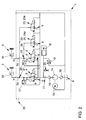
- the hydraulic circuit 1 is used to control at least one friction clutch, here of two friction clutches (not shown), and / or of several gear actuators of an automatic or automated motor vehicle transmission, wherein the transmission is also not shown.
- Vzw. the motor vehicle transmission is designed as a dual-clutch transmission and here the individual clutches of the double clutch are controlled or with the help of the working cylinder corresponding gear plate, vzw. Selected sliding sleeves, this depends on the particular application and the type of transmission, where such a hydraulic circuit is used.
- the hydraulic circuit 1 has a fluid as hydraulic fluid.
- the fluid is vzw. designed as a hydraulic oil.
- the hydraulic circuit 1 has at least one working cylinder.
- the hydraulic circuit 1 has two working cylinders 2 and 3.
- the working cylinders 2 and 3 can be used to actuate the two friction clutches of the dual-clutch transmission, or with the aid of the working cylinder corresponding gear actuator and / or sliding sleeves are controlled. This depends on the particular application. With the hydraulic circuit 1, the working cylinders 2 and 3 can be controlled precisely and quickly at a high power density.
- the hydraulic circuit 1 has per cylinder 2, 3 vzw. depending on a pressure control valve 4 and 5 respectively.
- Each cylinder 2, 3 is vzw. one of the pressure control valves 4, 5 assigned.
- the pressure control valves 4, 5 are vzw. continuously adjustable or controllable.
- Each of the pressure control valves 4, 5 is connected to the associated working cylinder 2, 3 via a cylinder line 2a, 3a.
- the pressure control valve 4, 5 is vzw. designed as a 3/2-way valve.
- the pressure control valve 4, 5 has vzw. three ports on, namely a working cylinder port 6, a working pressure port 7 and a base pressure port 8.
- the working cylinder port 6 is operatively connected in each case with the associated working cylinder 2 and 3 respectively.
- the working pressure port 7 is acted upon by a working pressure and is usually used as an inlet, as indicated by the arrow P1.
- a working pressure is usually used as an inlet, as indicated by the arrow P1.
- a lower base pressure is a lower base pressure and serves as a drain, as indicated by the arrow P2.
- the base pressure port 8 may be depressurized and operatively connected to a sump 9.
- the sump 9 can be formed by a container, not shown, for the fluid.
- the sump 9 can also be designed as a sump of the motor vehicle transmission.
- the working cylinder connection 6 is in particular functionally and effectively connected to a pressure chamber 10 of the respective working cylinder 2 and 3, respectively.
- the working pressure port 7 and the working cylinder port 6 are connected in the forward direction to each other, so that the fluid to the working cylinder 2,3 can flow, which is indicated here by the arrow P3.
- the working cylinder port 6 is connected to the cylinder line 2a and 3a, respectively (see. Fig. 1 and Fig. 2 ).
- the pressure regulating valve 4, 5 vzw. a slider 11.
- the pressure control valve 4, 5 connects the pressure chamber 10 of the working cylinder 2 and 3 via the slide 11 to the pressure build-up with the working pressure port 7 and the pressure reduction with the base pressure port 8.
- the slider 11 is biased here with a spring 12.
- the slider 11 is connected via a feedback 13 to the pressure in the cylinder line 2a, 3a, wherein the feedback 13 in the Fig. 1 and 2 dash-dotted lines is shown.
- the feedback 13 acts opposite to the spring bias, whereby the position of the slider 11 in the pressure control valve 4, 5 is fixed.
- the slider 11 has a plurality of unspecified control edges, with which the working pressure port 7 and base pressure port 8 are alternately closed and connectable to the working cylinder port 6. Due to the position of the slide 11 and thus the position of the control edges relative to the three terminals, the pressure in the pressure chamber 10 is adjustable. In addition to the spring 12, a further force can be applied to the slider 11, whereby the adjusted pressure is adjustable.
- a pump 14 is provided in the hydraulic circuit 1 to generate the working pressure.
- the working pressure port 7 is functionally effectively connected to the pump 14.
- the pump 14 is electric, here by a Electric motor 15 (M) drivable or is driven here.
- M Electric motor 15
- a pressure filter 16 and a check valve 17 is arranged between the pressure control valves 4, 5 and the pump 14.
- the working pressure is further applied to an accumulator device 18, wherein the accumulator device 18 is functionally effective between the pump 14 and the working pressure port 7 in the hydraulic circuit 1 is arranged.
- the working pressure is measured with a working pressure sensor 19.
- a pressure relief valve 20 is operatively arranged, the pressure relief valve 20 opens to the sump 9 of the transmission, if the working pressure increases too much.
- the hydraulic circuit 1 further has at least one leakage point, here vzw. a first leakage point 21 and a second leakage point 22.
- Each of the leakage points 21 and 22 can be switched off with an associated leakage valve 23 or 24, ie "closable".
- the leakage points 21, 22 and the leakage valves 23, 24 are designed and / or arranged such that the pressure reduction in the pressure control valves 4, 5, the working cylinder port 6 and the working pressure port 7 in manlassraum can be throttled and the pressure in the working cylinder 2, 3 via the respective leakage point 21, 22 is degradable.
- There are leakage lines 25, 26 are present, the leakage lines 25, 26 branch off between the pressure control valves 4, 5 and the working cylinders 2, 3 of the cylinder lines 2a, 3a to the sump 9 and the leakage valves 23, 24 have.
- the leakage points 21, 22 are artificially formed. For example. can the leakage points 21, 22 are produced by drilling or existing leaks are extended by drilling.
- Vzw. is the respective leakage valve 23, 24 continuously adjustable.
- the leakage valves 23, 24 can be designed as flow control valves 23a, 24a, in particular as 3/2-way valves, as in Fig. 2 is shown. This has the advantage that such a valve could simultaneously take over the function as a safety valve.
- the leakage valves 23, 24 may alternatively be designed as on / off valves 23b, 24b, in particular as 2/2-way valves, as in Fig. 1 is shown.
- the pump 14 does not have to provide a permanent fluid flow, it makes sense to minimize the leakage of the hydraulic circuit 1, which is achieved by closing the leakage valves 23, 24. This makes it possible to convey the fluid with the electrically driven pump 14.
- the pump 14 runs only when needed, which improves the efficiency of the hydraulic circuit 1. So that the pump 14 does not start and then switches off again shortly thereafter, the pressure storage device 18 is provided, wherein from the pressure storage device 18, the working pressure for a certain time without pump power is available.
- the leakage valves 23, 24 By switching off by means of the leakage valves 23, 24, the advantages of a leakage-prone pressure-controlled hydraulic circuit 1 with the advantages of a leak-free hydraulic circuit 1 are combined.
- the leakage points 21, 22 via the leakage valves 23, 24 are switched on.
- uncritical phases when the pressure in the pressure chamber 10 of the working cylinder 2, 3 corresponds to the working pressure or the base pressure and therefore no high demands are placed on the control quality, the leakage points 21, 22 via the leakage valves 23, 24 are turned off.
- the working cylinder 2, 3 and the Working cylinder connection 6 applied pressure is vzw. measurable with a pressure sensor 27 or 28.
- the hydraulic circuit 1 has an overflow 29.
- the overflow 29 can serve for venting and for filling hydraulic oil, etc. on the transmission, not shown.
- the pumped from the pump 14 from the sump 9 hydraulic oil is filtered through a sieve 30.
Landscapes
- Engineering & Computer Science (AREA)
- General Engineering & Computer Science (AREA)
- Mechanical Engineering (AREA)
- Physics & Mathematics (AREA)
- Fluid Mechanics (AREA)
- Fluid-Pressure Circuits (AREA)
- Hydraulic Clutches, Magnetic Clutches, Fluid Clutches, And Fluid Joints (AREA)
Applications Claiming Priority (1)
| Application Number | Priority Date | Filing Date | Title |
|---|---|---|---|
| DE102008037235A DE102008037235A1 (de) | 2008-08-09 | 2008-08-09 | Hydraulikkreislauf |
Publications (2)
| Publication Number | Publication Date |
|---|---|
| EP2151586A2 true EP2151586A2 (fr) | 2010-02-10 |
| EP2151586A3 EP2151586A3 (fr) | 2014-03-12 |
Family
ID=41258458
Family Applications (1)
| Application Number | Title | Priority Date | Filing Date |
|---|---|---|---|
| EP09008112.6A Withdrawn EP2151586A3 (fr) | 2008-08-09 | 2009-06-20 | Circuit hydraulique |
Country Status (2)
| Country | Link |
|---|---|
| EP (1) | EP2151586A3 (fr) |
| DE (1) | DE102008037235A1 (fr) |
Cited By (27)
| Publication number | Priority date | Publication date | Assignee | Title |
|---|---|---|---|---|
| US8192176B2 (en) | 2009-12-10 | 2012-06-05 | GM Global Technology Operations LLC | Hydraulic fluid supply system having active regulator |
| US8225687B2 (en) | 2009-09-09 | 2012-07-24 | GM Global Technology Operations LLC | Hydraulic control systems for dual clutch transmissions |
| US8402855B2 (en) | 2010-01-11 | 2013-03-26 | GM Global Technology Operations LLC | Hydraulic control systems for dual clutch transmissions |
| US8403792B2 (en) | 2009-10-21 | 2013-03-26 | GM Global Technology Operations LLC | Hydraulic control systems for dual clutch transmissions |
| US8403793B2 (en) | 2010-02-17 | 2013-03-26 | GM Global Technology Operations LLC | Hydraulic control system for an automatic transmission having a lubrication regulation valve |
| US8413777B2 (en) | 2010-02-17 | 2013-04-09 | GM Global Technology Operations LLC | High efficiency hydraulic transmission control system |
| US8413437B2 (en) | 2009-12-08 | 2013-04-09 | GM Global Technology Operations LLC | Transmission hydraulic control system having independently controlled stator cooling flow |
| US8429994B2 (en) | 2009-09-09 | 2013-04-30 | GM Global Technology Operations LLC | Hydraulic control systems for dual clutch transmissions |
| US8435148B2 (en) | 2010-01-11 | 2013-05-07 | GM Global Technology Operations LLC | Hydraulic control system for an automatic transmission having electronic transmission range selection with failure mode control |
| US8443687B2 (en) | 2009-12-14 | 2013-05-21 | GM Global Technology Operations LLC | Electro-hydraulic control system for a dual clutch transmission |
| US8475336B2 (en) | 2009-07-30 | 2013-07-02 | GM Global Technology Operations LLC | Hydraulic control system for a dual clutch transmission |
| US8500600B2 (en) | 2011-01-10 | 2013-08-06 | GM Global Technology Operations LLC | Hydraulic control system for an automatic transmission having a manual valve with a two gear default strategy |
| US8567580B2 (en) | 2010-01-22 | 2013-10-29 | GM Global Technology Operations LLC | Electro-hydraulic control system for a dual clutch transmission |
| US8579094B2 (en) | 2010-01-11 | 2013-11-12 | GM Global Technology Operations LLC | Hydraulic control system for an automatic transmission having a three path torque converter control subsystem |
| US8702548B2 (en) | 2011-11-03 | 2014-04-22 | Gm Global Technology Operations | Hydraulic control system for an automatic transmission |
| WO2014072273A1 (fr) * | 2012-11-09 | 2014-05-15 | Volkswagen Aktiengesellschaft | Dispositif de commande hydraulique |
| US8733521B2 (en) | 2010-12-06 | 2014-05-27 | Gm Global Technology Operations | Apparatus for and method of controlling a dual clutch transmission |
| US8738257B2 (en) | 2010-12-08 | 2014-05-27 | Gm Global Technology Operations, Llc | Electro-hydraulic control system and method for a dual clutch transmission |
| US8740748B2 (en) | 2010-12-08 | 2014-06-03 | Gm Global Technology Operations, Llc | Control system and method for a dual clutch transmission |
| CN103851105A (zh) * | 2012-12-07 | 2014-06-11 | 上海汽车集团股份有限公司 | 一种液压式分离系统 |
| US8839928B2 (en) | 2010-12-02 | 2014-09-23 | Gm Global Technology Operations, Llc | Electro-hydraulic control system for a dual clutch transmission |
| US8915076B2 (en) | 2011-01-12 | 2014-12-23 | Gm Global Technology Operations, Llc | Transmission hydraulic control system having flow augmentation |
| US8942901B2 (en) | 2010-12-09 | 2015-01-27 | Gm Global Technology Operations, Llc | Method of controlling a hydraulic control system for a dual clutch transmission |
| US9080666B2 (en) | 2012-05-29 | 2015-07-14 | Gm Global Technology Operations, Inc. | Discrete mechanism for electronic transmission range selection |
| US10167948B2 (en) | 2016-03-17 | 2019-01-01 | GM Global Technology Operations LLC | Hydraulic control system for an automatic transmission |
| WO2020216396A1 (fr) * | 2019-04-25 | 2020-10-29 | Schaeffler Technologies AG & Co. KG | Procédé de commande d'un système hydraulique pourvu d'une pompe et de plusieurs vannes, et système hydraulique |
| CN113748272A (zh) * | 2019-04-25 | 2021-12-03 | 舍弗勒技术股份两合公司 | 用于对多个消耗器及冷却和/或润滑装置进行供应的具有泵和阀的液压系统的驱动方法以及液压系统 |
Families Citing this family (1)
| Publication number | Priority date | Publication date | Assignee | Title |
|---|---|---|---|---|
| DE102014111721A1 (de) | 2014-08-18 | 2016-02-18 | Getrag Getriebe- Und Zahnradfabrik Hermann Hagenmeyer Gmbh & Cie Kg | Fluidbeaufschlagungsvorrichtung für ein Getriebe für ein Kraftfahrzeug |
Citations (2)
| Publication number | Priority date | Publication date | Assignee | Title |
|---|---|---|---|---|
| EP1446349B1 (fr) | 2001-11-23 | 2005-04-27 | Bucher Hydraulics AG | Ascenseur hydraulique equipe d'un accumulateur de pression et son procede de commande et de reglage |
| EP1574720A1 (fr) * | 2004-03-10 | 2005-09-14 | HAWE Hydraulik GmbH & Co. KG | Commande électro-hydraulique |
Family Cites Families (9)
| Publication number | Priority date | Publication date | Assignee | Title |
|---|---|---|---|---|
| DE2043196C3 (de) * | 1970-09-01 | 1979-01-25 | Zahnradfabrik Friedrichshafen Ag, 7990 Friedrichshafen | Einrichtung zur Drucksteuerung für Lastschaltgetriebe |
| CH563532A5 (fr) * | 1973-03-14 | 1975-06-30 | Buehler Ag Geb | |
| IT1144396B (it) * | 1981-07-17 | 1986-10-29 | Fiat Auto Spa | Apparecchiatura per il controllo di un cambio automatico continuo di un autoveicolo |
| DE3811615C1 (en) * | 1988-04-07 | 1989-11-30 | Hanomag Ag, 3000 Hannover, De | Control device for friction clutches, shiftable by hydraulic pressure, of a multigear power-shift transmission for vehicles |
| DE4201692B4 (de) * | 1991-02-02 | 2008-05-15 | Luk Lamellen Und Kupplungsbau Beteiligungs Kg | Stufenlos einstellbares Kegelscheibenumschlingungsgetriebe |
| DE19815666B4 (de) * | 1997-05-15 | 2011-03-17 | Zf Sachs Ag | Verfahren zum Betreiben eines Stellantriebs zur automatisierten Betätigung einer Reibungskupplung und eines automatisierten Schaltgetriebes |
| DE10102375A1 (de) * | 2000-04-14 | 2001-10-18 | Mannesmann Sachs Ag | Kupplungsbetätigungseinrichtung mit Behelfsbetätigungsanordnung |
| US7204084B2 (en) * | 2004-10-29 | 2007-04-17 | Caterpillar Inc | Hydraulic system having a pressure compensator |
| DE102005021416A1 (de) * | 2005-05-10 | 2006-11-16 | Zf Friedrichshafen Ag | Antriebsstrang eines Kraftfahrzeugs und Verfahren zur Steuerung einer automatisierten Motorkupplung |
-
2008
- 2008-08-09 DE DE102008037235A patent/DE102008037235A1/de not_active Withdrawn
-
2009
- 2009-06-20 EP EP09008112.6A patent/EP2151586A3/fr not_active Withdrawn
Patent Citations (2)
| Publication number | Priority date | Publication date | Assignee | Title |
|---|---|---|---|---|
| EP1446349B1 (fr) | 2001-11-23 | 2005-04-27 | Bucher Hydraulics AG | Ascenseur hydraulique equipe d'un accumulateur de pression et son procede de commande et de reglage |
| EP1574720A1 (fr) * | 2004-03-10 | 2005-09-14 | HAWE Hydraulik GmbH & Co. KG | Commande électro-hydraulique |
Cited By (34)
| Publication number | Priority date | Publication date | Assignee | Title |
|---|---|---|---|---|
| US8475336B2 (en) | 2009-07-30 | 2013-07-02 | GM Global Technology Operations LLC | Hydraulic control system for a dual clutch transmission |
| US8429994B2 (en) | 2009-09-09 | 2013-04-30 | GM Global Technology Operations LLC | Hydraulic control systems for dual clutch transmissions |
| US8225687B2 (en) | 2009-09-09 | 2012-07-24 | GM Global Technology Operations LLC | Hydraulic control systems for dual clutch transmissions |
| US8403792B2 (en) | 2009-10-21 | 2013-03-26 | GM Global Technology Operations LLC | Hydraulic control systems for dual clutch transmissions |
| US8413437B2 (en) | 2009-12-08 | 2013-04-09 | GM Global Technology Operations LLC | Transmission hydraulic control system having independently controlled stator cooling flow |
| US8192176B2 (en) | 2009-12-10 | 2012-06-05 | GM Global Technology Operations LLC | Hydraulic fluid supply system having active regulator |
| US8443687B2 (en) | 2009-12-14 | 2013-05-21 | GM Global Technology Operations LLC | Electro-hydraulic control system for a dual clutch transmission |
| US8435148B2 (en) | 2010-01-11 | 2013-05-07 | GM Global Technology Operations LLC | Hydraulic control system for an automatic transmission having electronic transmission range selection with failure mode control |
| US8402855B2 (en) | 2010-01-11 | 2013-03-26 | GM Global Technology Operations LLC | Hydraulic control systems for dual clutch transmissions |
| US8579094B2 (en) | 2010-01-11 | 2013-11-12 | GM Global Technology Operations LLC | Hydraulic control system for an automatic transmission having a three path torque converter control subsystem |
| US8567580B2 (en) | 2010-01-22 | 2013-10-29 | GM Global Technology Operations LLC | Electro-hydraulic control system for a dual clutch transmission |
| US8413777B2 (en) | 2010-02-17 | 2013-04-09 | GM Global Technology Operations LLC | High efficiency hydraulic transmission control system |
| US8403793B2 (en) | 2010-02-17 | 2013-03-26 | GM Global Technology Operations LLC | Hydraulic control system for an automatic transmission having a lubrication regulation valve |
| US8839928B2 (en) | 2010-12-02 | 2014-09-23 | Gm Global Technology Operations, Llc | Electro-hydraulic control system for a dual clutch transmission |
| US8733521B2 (en) | 2010-12-06 | 2014-05-27 | Gm Global Technology Operations | Apparatus for and method of controlling a dual clutch transmission |
| US8738257B2 (en) | 2010-12-08 | 2014-05-27 | Gm Global Technology Operations, Llc | Electro-hydraulic control system and method for a dual clutch transmission |
| US8740748B2 (en) | 2010-12-08 | 2014-06-03 | Gm Global Technology Operations, Llc | Control system and method for a dual clutch transmission |
| US9765885B2 (en) | 2010-12-09 | 2017-09-19 | GM Global Technology Operations LLC | Method of controlling a hydraulic control system for a dual clutch transmission |
| US8942901B2 (en) | 2010-12-09 | 2015-01-27 | Gm Global Technology Operations, Llc | Method of controlling a hydraulic control system for a dual clutch transmission |
| US8500600B2 (en) | 2011-01-10 | 2013-08-06 | GM Global Technology Operations LLC | Hydraulic control system for an automatic transmission having a manual valve with a two gear default strategy |
| US8915076B2 (en) | 2011-01-12 | 2014-12-23 | Gm Global Technology Operations, Llc | Transmission hydraulic control system having flow augmentation |
| US8702548B2 (en) | 2011-11-03 | 2014-04-22 | Gm Global Technology Operations | Hydraulic control system for an automatic transmission |
| US9080666B2 (en) | 2012-05-29 | 2015-07-14 | Gm Global Technology Operations, Inc. | Discrete mechanism for electronic transmission range selection |
| CN104769335B (zh) * | 2012-11-09 | 2017-11-17 | 大众汽车有限公司 | 液压控制装置 |
| CN104769335A (zh) * | 2012-11-09 | 2015-07-08 | 大众汽车有限公司 | 液压控制装置 |
| WO2014072273A1 (fr) * | 2012-11-09 | 2014-05-15 | Volkswagen Aktiengesellschaft | Dispositif de commande hydraulique |
| CN103851105B (zh) * | 2012-12-07 | 2016-05-18 | 上海汽车集团股份有限公司 | 一种液压式分离系统 |
| CN103851105A (zh) * | 2012-12-07 | 2014-06-11 | 上海汽车集团股份有限公司 | 一种液压式分离系统 |
| US10167948B2 (en) | 2016-03-17 | 2019-01-01 | GM Global Technology Operations LLC | Hydraulic control system for an automatic transmission |
| WO2020216396A1 (fr) * | 2019-04-25 | 2020-10-29 | Schaeffler Technologies AG & Co. KG | Procédé de commande d'un système hydraulique pourvu d'une pompe et de plusieurs vannes, et système hydraulique |
| CN113748272A (zh) * | 2019-04-25 | 2021-12-03 | 舍弗勒技术股份两合公司 | 用于对多个消耗器及冷却和/或润滑装置进行供应的具有泵和阀的液压系统的驱动方法以及液压系统 |
| CN113767224A (zh) * | 2019-04-25 | 2021-12-07 | 舍弗勒技术股份两合公司 | 用于具有泵和多个阀的液压系统的致动方法以及液压系统 |
| US11703094B2 (en) | 2019-04-25 | 2023-07-18 | Schaeffler Technologies AG & Co. KG | Actuation method for a hydraulic system with a pump and multiple valves, and hydraulic system |
| US11920645B2 (en) | 2019-04-25 | 2024-03-05 | Schaeffler Technologies AG &Co. KG | Actuation method for a hydraulic system having a pump and valves for supplying multiple consumers and a cooling and/or lubricating device, and hydraulic system |
Also Published As
| Publication number | Publication date |
|---|---|
| DE102008037235A1 (de) | 2010-02-11 |
| EP2151586A3 (fr) | 2014-03-12 |
Similar Documents
| Publication | Publication Date | Title |
|---|---|---|
| EP2151586A2 (fr) | Circuit hydraulique | |
| DE102006016397B4 (de) | Getriebe und ein Verfahren zur Steuerung eines Getriebes für ein Kraftfahrzeug | |
| EP2609348B1 (fr) | Commande hydraulique pour une transmission automatique d'un véhicule automobile | |
| EP2705277B1 (fr) | Boîte de vitesses à double embrayage | |
| EP2739882B2 (fr) | Commande hydraulique pour une transmission automatique d'un véhicule automobile | |
| WO2011015182A1 (fr) | Système hydraulique de commande hydraulique d'une boîte de vitesses à double embrayage | |
| DE10243282A1 (de) | Hydraulische Steuerungsvorrichtung eines Doppelkupplungsgetriebes | |
| EP3227587A2 (fr) | Ensemble frein de stationnement | |
| DE102011109377A1 (de) | Hydraulische Steuerung für ein Automatikgetriebe eines Kraftfahrzeugs | |
| DE102011100838B4 (de) | Doppelkupplungsgetriebe, mit wenigstens einer Pumpe, einem der Pumpe nachgeschalteten Volumensteuerventil, einem der Pumpe nachgeschalteten Kühler und einem dem Kühler nachgeschalteten Schaltventil | |
| WO2012152395A1 (fr) | Boîte de vitesses à embrayage, en particulier boîte de vitesses à double embrayage, dotée d'un accumulateur de pression | |
| WO2012152382A1 (fr) | Boîte de vitesses à embrayage et son procédé de fonctionnement | |
| EP1522754A1 (fr) | Alimentation en fluide sous pression pour système d'embrayage et train de propulsion pour vehicules avec cette alimentation en fluide sous pression. | |
| DE102006003517A1 (de) | Hydraulische Steuereinrichtung und Verfahren zur Ansteuerung zweier Aktuatoren | |
| WO2012152398A1 (fr) | Boîte de vitesses à double embrayage | |
| DE102011100809B4 (de) | Kupplungsgetriebe mit Sicherheitsventilanordnung | |
| DE102011100799B4 (de) | Doppelkupplungsgetriebe, Verfahren zum Betreiben | |
| DE102006058913A1 (de) | Steuerungsvorrichtung für ein Getriebe | |
| DE102007023072A1 (de) | Hydraulische Steuerungseinrichtung für ein Getriebe | |
| EP2767738B1 (fr) | Agencement de commande hydraulique, engrenage doté de celui-ci et procédé de pré-remplissage | |
| DE102014117625A1 (de) | Schaltgetriebe eines Kraftfahrzeugs | |
| WO2019086424A1 (fr) | Vanne, système hydraulique et boîte de vitesses de véhicule automobile | |
| EP3254000B1 (fr) | Système de propulsion | |
| DE102011100810B4 (de) | Doppelkupplungsgetriebe, Verfahren zum Betreiben | |
| DE102006063034B3 (de) | Verfahren zur Steuerung eines Getriebes für ein Kraftfahrzeug |
Legal Events
| Date | Code | Title | Description |
|---|---|---|---|
| PUAI | Public reference made under article 153(3) epc to a published international application that has entered the european phase |
Free format text: ORIGINAL CODE: 0009012 |
|
| AK | Designated contracting states |
Kind code of ref document: A2 Designated state(s): AT BE BG CH CY CZ DE DK EE ES FI FR GB GR HR HU IE IS IT LI LT LU LV MC MK MT NL NO PL PT RO SE SI SK TR |
|
| AX | Request for extension of the european patent |
Extension state: AL BA RS |
|
| RAP1 | Party data changed (applicant data changed or rights of an application transferred) |
Owner name: VOLKSWAGEN AKTIENGESELLSCHAFT |
|
| PUAL | Search report despatched |
Free format text: ORIGINAL CODE: 0009013 |
|
| AK | Designated contracting states |
Kind code of ref document: A3 Designated state(s): AT BE BG CH CY CZ DE DK EE ES FI FR GB GR HR HU IE IS IT LI LT LU LV MC MK MT NL NO PL PT RO SE SI SK TR |
|
| AX | Request for extension of the european patent |
Extension state: AL BA RS |
|
| RIC1 | Information provided on ipc code assigned before grant |
Ipc: F16D 48/02 20060101ALN20140203BHEP Ipc: F16H 61/688 20060101ALN20140203BHEP Ipc: F15B 11/16 20060101AFI20140203BHEP |
|
| 17P | Request for examination filed |
Effective date: 20140912 |
|
| RBV | Designated contracting states (corrected) |
Designated state(s): AT BE BG CH CY CZ DE DK EE ES FI FR GB GR HR HU IE IS IT LI LT LU LV MC MK MT NL NO PL PT RO SE SI SK TR |
|
| 17Q | First examination report despatched |
Effective date: 20151216 |
|
| STAA | Information on the status of an ep patent application or granted ep patent |
Free format text: STATUS: THE APPLICATION IS DEEMED TO BE WITHDRAWN |
|
| 18D | Application deemed to be withdrawn |
Effective date: 20160427 |