EP1522754A1 - Alimentation en fluide sous pression pour système d'embrayage et train de propulsion pour vehicules avec cette alimentation en fluide sous pression. - Google Patents
Alimentation en fluide sous pression pour système d'embrayage et train de propulsion pour vehicules avec cette alimentation en fluide sous pression. Download PDFInfo
- Publication number
- EP1522754A1 EP1522754A1 EP04024024A EP04024024A EP1522754A1 EP 1522754 A1 EP1522754 A1 EP 1522754A1 EP 04024024 A EP04024024 A EP 04024024A EP 04024024 A EP04024024 A EP 04024024A EP 1522754 A1 EP1522754 A1 EP 1522754A1
- Authority
- EP
- European Patent Office
- Prior art keywords
- pressure medium
- pressure
- valve
- drive train
- medium
- Prior art date
- Legal status (The legal status is an assumption and is not a legal conclusion. Google has not performed a legal analysis and makes no representation as to the accuracy of the status listed.)
- Granted
Links
Images


Classifications
-
- F—MECHANICAL ENGINEERING; LIGHTING; HEATING; WEAPONS; BLASTING
- F16—ENGINEERING ELEMENTS AND UNITS; GENERAL MEASURES FOR PRODUCING AND MAINTAINING EFFECTIVE FUNCTIONING OF MACHINES OR INSTALLATIONS; THERMAL INSULATION IN GENERAL
- F16H—GEARING
- F16H61/00—Control functions within control units of change-speed- or reversing-gearings for conveying rotary motion ; Control of exclusively fluid gearing, friction gearing, gearings with endless flexible members or other particular types of gearing
- F16H61/0021—Generation or control of line pressure
-
- F—MECHANICAL ENGINEERING; LIGHTING; HEATING; WEAPONS; BLASTING
- F15—FLUID-PRESSURE ACTUATORS; HYDRAULICS OR PNEUMATICS IN GENERAL
- F15B—SYSTEMS ACTING BY MEANS OF FLUIDS IN GENERAL; FLUID-PRESSURE ACTUATORS, e.g. SERVOMOTORS; DETAILS OF FLUID-PRESSURE SYSTEMS, NOT OTHERWISE PROVIDED FOR
- F15B20/00—Safety arrangements for fluid actuator systems; Applications of safety devices in fluid actuator systems; Emergency measures for fluid actuator systems
- F15B20/004—Fluid pressure supply failure
-
- F—MECHANICAL ENGINEERING; LIGHTING; HEATING; WEAPONS; BLASTING
- F16—ENGINEERING ELEMENTS AND UNITS; GENERAL MEASURES FOR PRODUCING AND MAINTAINING EFFECTIVE FUNCTIONING OF MACHINES OR INSTALLATIONS; THERMAL INSULATION IN GENERAL
- F16D—COUPLINGS FOR TRANSMITTING ROTATION; CLUTCHES; BRAKES
- F16D48/00—External control of clutches
- F16D48/02—Control by fluid pressure
- F16D48/0206—Control by fluid pressure in a system with a plurality of fluid-actuated clutches
-
- F—MECHANICAL ENGINEERING; LIGHTING; HEATING; WEAPONS; BLASTING
- F16—ENGINEERING ELEMENTS AND UNITS; GENERAL MEASURES FOR PRODUCING AND MAINTAINING EFFECTIVE FUNCTIONING OF MACHINES OR INSTALLATIONS; THERMAL INSULATION IN GENERAL
- F16D—COUPLINGS FOR TRANSMITTING ROTATION; CLUTCHES; BRAKES
- F16D48/00—External control of clutches
- F16D48/02—Control by fluid pressure
- F16D48/04—Control by fluid pressure providing power assistance
-
- F—MECHANICAL ENGINEERING; LIGHTING; HEATING; WEAPONS; BLASTING
- F16—ENGINEERING ELEMENTS AND UNITS; GENERAL MEASURES FOR PRODUCING AND MAINTAINING EFFECTIVE FUNCTIONING OF MACHINES OR INSTALLATIONS; THERMAL INSULATION IN GENERAL
- F16H—GEARING
- F16H61/00—Control functions within control units of change-speed- or reversing-gearings for conveying rotary motion ; Control of exclusively fluid gearing, friction gearing, gearings with endless flexible members or other particular types of gearing
- F16H61/12—Detecting malfunction or potential malfunction, e.g. fail safe; Circumventing or fixing failures
-
- B—PERFORMING OPERATIONS; TRANSPORTING
- B60—VEHICLES IN GENERAL
- B60W—CONJOINT CONTROL OF VEHICLE SUB-UNITS OF DIFFERENT TYPE OR DIFFERENT FUNCTION; CONTROL SYSTEMS SPECIALLY ADAPTED FOR HYBRID VEHICLES; ROAD VEHICLE DRIVE CONTROL SYSTEMS FOR PURPOSES NOT RELATED TO THE CONTROL OF A PARTICULAR SUB-UNIT
- B60W2510/00—Input parameters relating to a particular sub-units
- B60W2510/10—Change speed gearings
- B60W2510/1075—Change speed gearings fluid pressure, e.g. oil pressure
-
- F—MECHANICAL ENGINEERING; LIGHTING; HEATING; WEAPONS; BLASTING
- F15—FLUID-PRESSURE ACTUATORS; HYDRAULICS OR PNEUMATICS IN GENERAL
- F15B—SYSTEMS ACTING BY MEANS OF FLUIDS IN GENERAL; FLUID-PRESSURE ACTUATORS, e.g. SERVOMOTORS; DETAILS OF FLUID-PRESSURE SYSTEMS, NOT OTHERWISE PROVIDED FOR
- F15B2211/00—Circuits for servomotor systems
- F15B2211/20—Fluid pressure source, e.g. accumulator or variable axial piston pump
- F15B2211/205—Systems with pumps
- F15B2211/20576—Systems with pumps with multiple pumps
-
- F—MECHANICAL ENGINEERING; LIGHTING; HEATING; WEAPONS; BLASTING
- F15—FLUID-PRESSURE ACTUATORS; HYDRAULICS OR PNEUMATICS IN GENERAL
- F15B—SYSTEMS ACTING BY MEANS OF FLUIDS IN GENERAL; FLUID-PRESSURE ACTUATORS, e.g. SERVOMOTORS; DETAILS OF FLUID-PRESSURE SYSTEMS, NOT OTHERWISE PROVIDED FOR
- F15B2211/00—Circuits for servomotor systems
- F15B2211/80—Other types of control related to particular problems or conditions
- F15B2211/86—Control during or prevention of abnormal conditions
- F15B2211/863—Control during or prevention of abnormal conditions the abnormal condition being a hydraulic or pneumatic failure
- F15B2211/8633—Pressure source supply failure
-
- F—MECHANICAL ENGINEERING; LIGHTING; HEATING; WEAPONS; BLASTING
- F15—FLUID-PRESSURE ACTUATORS; HYDRAULICS OR PNEUMATICS IN GENERAL
- F15B—SYSTEMS ACTING BY MEANS OF FLUIDS IN GENERAL; FLUID-PRESSURE ACTUATORS, e.g. SERVOMOTORS; DETAILS OF FLUID-PRESSURE SYSTEMS, NOT OTHERWISE PROVIDED FOR
- F15B2211/00—Circuits for servomotor systems
- F15B2211/80—Other types of control related to particular problems or conditions
- F15B2211/875—Control measures for coping with failures
- F15B2211/8752—Emergency operation mode, e.g. fail-safe operation mode
-
- F—MECHANICAL ENGINEERING; LIGHTING; HEATING; WEAPONS; BLASTING
- F15—FLUID-PRESSURE ACTUATORS; HYDRAULICS OR PNEUMATICS IN GENERAL
- F15B—SYSTEMS ACTING BY MEANS OF FLUIDS IN GENERAL; FLUID-PRESSURE ACTUATORS, e.g. SERVOMOTORS; DETAILS OF FLUID-PRESSURE SYSTEMS, NOT OTHERWISE PROVIDED FOR
- F15B2211/00—Circuits for servomotor systems
- F15B2211/80—Other types of control related to particular problems or conditions
- F15B2211/875—Control measures for coping with failures
- F15B2211/8757—Control measures for coping with failures using redundant components or assemblies
-
- F—MECHANICAL ENGINEERING; LIGHTING; HEATING; WEAPONS; BLASTING
- F16—ENGINEERING ELEMENTS AND UNITS; GENERAL MEASURES FOR PRODUCING AND MAINTAINING EFFECTIVE FUNCTIONING OF MACHINES OR INSTALLATIONS; THERMAL INSULATION IN GENERAL
- F16D—COUPLINGS FOR TRANSMITTING ROTATION; CLUTCHES; BRAKES
- F16D2300/00—Special features for couplings or clutches
- F16D2300/14—Clutches which are normally open, i.e. not engaged in released state
-
- F—MECHANICAL ENGINEERING; LIGHTING; HEATING; WEAPONS; BLASTING
- F16—ENGINEERING ELEMENTS AND UNITS; GENERAL MEASURES FOR PRODUCING AND MAINTAINING EFFECTIVE FUNCTIONING OF MACHINES OR INSTALLATIONS; THERMAL INSULATION IN GENERAL
- F16D—COUPLINGS FOR TRANSMITTING ROTATION; CLUTCHES; BRAKES
- F16D2500/00—External control of clutches by electric or electronic means
- F16D2500/10—System to be controlled
- F16D2500/102—Actuator
- F16D2500/1026—Hydraulic
-
- F—MECHANICAL ENGINEERING; LIGHTING; HEATING; WEAPONS; BLASTING
- F16—ENGINEERING ELEMENTS AND UNITS; GENERAL MEASURES FOR PRODUCING AND MAINTAINING EFFECTIVE FUNCTIONING OF MACHINES OR INSTALLATIONS; THERMAL INSULATION IN GENERAL
- F16D—COUPLINGS FOR TRANSMITTING ROTATION; CLUTCHES; BRAKES
- F16D2500/00—External control of clutches by electric or electronic means
- F16D2500/10—System to be controlled
- F16D2500/104—Clutch
- F16D2500/10406—Clutch position
- F16D2500/10412—Transmission line of a vehicle
-
- F—MECHANICAL ENGINEERING; LIGHTING; HEATING; WEAPONS; BLASTING
- F16—ENGINEERING ELEMENTS AND UNITS; GENERAL MEASURES FOR PRODUCING AND MAINTAINING EFFECTIVE FUNCTIONING OF MACHINES OR INSTALLATIONS; THERMAL INSULATION IN GENERAL
- F16D—COUPLINGS FOR TRANSMITTING ROTATION; CLUTCHES; BRAKES
- F16D2500/00—External control of clutches by electric or electronic means
- F16D2500/10—System to be controlled
- F16D2500/104—Clutch
- F16D2500/10443—Clutch type
- F16D2500/1045—Friction clutch
-
- F—MECHANICAL ENGINEERING; LIGHTING; HEATING; WEAPONS; BLASTING
- F16—ENGINEERING ELEMENTS AND UNITS; GENERAL MEASURES FOR PRODUCING AND MAINTAINING EFFECTIVE FUNCTIONING OF MACHINES OR INSTALLATIONS; THERMAL INSULATION IN GENERAL
- F16D—COUPLINGS FOR TRANSMITTING ROTATION; CLUTCHES; BRAKES
- F16D2500/00—External control of clutches by electric or electronic means
- F16D2500/10—System to be controlled
- F16D2500/108—Gear
- F16D2500/1086—Concentric shafts
-
- F—MECHANICAL ENGINEERING; LIGHTING; HEATING; WEAPONS; BLASTING
- F16—ENGINEERING ELEMENTS AND UNITS; GENERAL MEASURES FOR PRODUCING AND MAINTAINING EFFECTIVE FUNCTIONING OF MACHINES OR INSTALLATIONS; THERMAL INSULATION IN GENERAL
- F16D—COUPLINGS FOR TRANSMITTING ROTATION; CLUTCHES; BRAKES
- F16D2500/00—External control of clutches by electric or electronic means
- F16D2500/30—Signal inputs
- F16D2500/302—Signal inputs from the actuator
- F16D2500/3024—Pressure
-
- F—MECHANICAL ENGINEERING; LIGHTING; HEATING; WEAPONS; BLASTING
- F16—ENGINEERING ELEMENTS AND UNITS; GENERAL MEASURES FOR PRODUCING AND MAINTAINING EFFECTIVE FUNCTIONING OF MACHINES OR INSTALLATIONS; THERMAL INSULATION IN GENERAL
- F16D—COUPLINGS FOR TRANSMITTING ROTATION; CLUTCHES; BRAKES
- F16D2500/00—External control of clutches by electric or electronic means
- F16D2500/50—Problem to be solved by the control system
- F16D2500/51—Relating safety
- F16D2500/5114—Failsafe
-
- F—MECHANICAL ENGINEERING; LIGHTING; HEATING; WEAPONS; BLASTING
- F16—ENGINEERING ELEMENTS AND UNITS; GENERAL MEASURES FOR PRODUCING AND MAINTAINING EFFECTIVE FUNCTIONING OF MACHINES OR INSTALLATIONS; THERMAL INSULATION IN GENERAL
- F16D—COUPLINGS FOR TRANSMITTING ROTATION; CLUTCHES; BRAKES
- F16D2500/00—External control of clutches by electric or electronic means
- F16D2500/70—Details about the implementation of the control system
- F16D2500/704—Output parameters from the control unit; Target parameters to be controlled
- F16D2500/70402—Actuator parameters
- F16D2500/70406—Pressure
-
- F—MECHANICAL ENGINEERING; LIGHTING; HEATING; WEAPONS; BLASTING
- F16—ENGINEERING ELEMENTS AND UNITS; GENERAL MEASURES FOR PRODUCING AND MAINTAINING EFFECTIVE FUNCTIONING OF MACHINES OR INSTALLATIONS; THERMAL INSULATION IN GENERAL
- F16H—GEARING
- F16H61/00—Control functions within control units of change-speed- or reversing-gearings for conveying rotary motion ; Control of exclusively fluid gearing, friction gearing, gearings with endless flexible members or other particular types of gearing
- F16H61/12—Detecting malfunction or potential malfunction, e.g. fail safe; Circumventing or fixing failures
- F16H2061/122—Avoiding failures by using redundant parts
-
- F—MECHANICAL ENGINEERING; LIGHTING; HEATING; WEAPONS; BLASTING
- F16—ENGINEERING ELEMENTS AND UNITS; GENERAL MEASURES FOR PRODUCING AND MAINTAINING EFFECTIVE FUNCTIONING OF MACHINES OR INSTALLATIONS; THERMAL INSULATION IN GENERAL
- F16H—GEARING
- F16H61/00—Control functions within control units of change-speed- or reversing-gearings for conveying rotary motion ; Control of exclusively fluid gearing, friction gearing, gearings with endless flexible members or other particular types of gearing
- F16H61/12—Detecting malfunction or potential malfunction, e.g. fail safe; Circumventing or fixing failures
- F16H2061/1256—Detecting malfunction or potential malfunction, e.g. fail safe; Circumventing or fixing failures characterised by the parts or units where malfunctioning was assumed or detected
- F16H2061/126—Detecting malfunction or potential malfunction, e.g. fail safe; Circumventing or fixing failures characterised by the parts or units where malfunctioning was assumed or detected the failing part is the controller
- F16H2061/1264—Hydraulic parts of the controller, e.g. a sticking valve or clogged channel
Definitions
- the invention relates in one aspect to a motor vehicle powertrain, comprising a drive unit, a transmission and a clutch system with one disposed between the drive unit and the transmission Coupling device for torque transmission between the Drive unit and the transmission, wherein the coupling device at least one operable by mediation of pressure medium Coupling arrangement, wherein a pressure medium system on Basis of at least one coupling device associated Pump arrangement, the pressure medium for the actuation of Coupling arrangement can be provided by mediating at least one the pressure medium on an operating pressure nieenden, electrically controllable pressure control / regulating valve of the pressure medium system.
- a Automotive powertrain known, comprising a drive unit, a Transmission and a clutch system with one between the drive unit and the transmission arranged coupling device for Torque transmission between the drive unit and the transmission, wherein the coupling device at least one mediated by Pressure medium operable, for operation under the action of a Operating medium provided clutch arrangement, wherein on Basis of a pump arrangement, the pressure medium for the actuation the coupling arrangement can be provided and the coupling device for Operation under the action of the operating medium Operating medium can be fed.
- the coupling device may be, for example to a coupling device according to a construction of the applicant act, as in the German patent application DE 100 04 179 A1 is described, the disclosure of which is also by reference in the The disclosure of the present application is included.
- Coupling arrangements usually as without applied pressure medium automatically opening clutch arrangements, ie as Coupling arrangements of the NORMALLY OPEN type are executed, so that in case of a system failure not both clutch arrangements take the engaged state, which is when the motor vehicle to serious damage to the drive train, in particular of the transmission, could lead.
- system failure such as power failure or failure of the controller
- the invention seeks, at least one emergency operation of the motor vehicle regardless of an electrical power supply and / or the proper functioning of an electronic control circuit ensure, at least for an emergency operating period, approximately for one Maneuvering the motor vehicle or for driving away the motor vehicle sufficient from a hazardous area.
- the invention proposes at least one of Coupling device associated pressure medium emergency supply before, on whose basis is at least for at least one emergency drive of the Motor vehicle enabling emergency period independently of one electrical power supply and / or independent of proper Function of an electronic control circuit pressure medium for the Actuation of the clutch assembly or at least to hold the Coupling arrangement in an at least partially engaged state is available.
- the coupling device of NORMALLY OPEN-type is or that in case of several Coupling devices all of these NORMALLY OPEN type are. Furthermore, it is especially thought that in case of failure of the electrical energy the pressure control valve does not adequately Actuating pressure for the actuation of the clutch assembly or the Holding the clutch assembly in the at least partially engaged State provides and that based on the pressure medium emergency supply in case of failure of electrical energy and / or im Case of malfunction of the electronic control circuit Pressure medium on a for at least partially engaging the Coupling arrangement or at least for holding the clutch assembly sufficient in an at least partially engaged state Pressure level is available.
- the Coupling device for operation under the action of a Be provided operating medium wherein the coupling device on Basis of the pump arrangement Operating medium for operation under Impact of the operating medium can be fed.
- the transmission by means of an associated actuator by mediating pressure medium be actuated, wherein the pressure medium for the actuation of the transmission preferably based on the assigned on the transmission Pump arrangement can be provided.
- the pressure medium emergency supply the Pressure medium based on stored in a pressure accumulator Provides print media. For a sufficiently long emergency operating period is then under circumstances but a very large and expensive Pressure accumulator required. It is therefore preferred that the print medium emergency supply the print medium based on the pump assembly provides provided pressure medium. hereby can even an emergency drive of the motor vehicle for an unlimited limited only by the fuel supply or other factors Period allows. It will be especially important in this context thought that the pump assembly at least one through the Drive unit has drivable pump, based on the Pressure medium on the one / at least partially engaging the Coupling arrangement or at least for holding the clutch assembly sufficient in an at least partially engaged state Pressure level and preferably on the operating pressure can be provided.
- the pressure medium emergency supply expediently at least one pressure-reducing device, preferably have at least one pressure reducing valve, through which a on a discharge side of the pump assembly or the at least one Pump prevailing in the driven state by the drive unit Pressure level on a / at least partially engaging the Coupling arrangement or at least for holding the clutch assembly in an at least partially engaged state sufficient (s), on the pressure rating of a coupler side Pressure medium system section or / and at least one Actuating cylinder of the clutch system tuned (s) pressure level is reducible.
- the pressure medium system is designed for a failure of the electrical energy supply to address and in response to a failure of the electrical Switch power supply from a first Pressure medium supply state in which the pressure control valve the Druckmedium provides or adjusts the actuation pressure, in a second print medium supply state in which the pressure medium emergency supply provides the print medium.
- This is a manual Switching on the pressure medium emergency supply by the driver dispensable.
- the first print medium supply state corresponds, a Pressure medium connection between the pressure control / regulating valve and one / the actuating cylinder of the coupling device releases and a to the actuating cylinder leading pressure medium connection of Pressure medium emergency supply interrupts and in a second Switching state, the second pressure medium supply state corresponds to the pressure medium connection between the pressure control valve and the actuating cylinder of the coupling device interrupts and leading to the actuating cylinder Pressure medium connection of the pressure medium emergency supply releases.
- the pressure medium connection is usually one Hydraulic connection and the actuating cylinder usually to a hydraulic actuator or slave cylinder will act.
- the switching valve as electrical controllable valve is executed and in the energized state the first Switching state and in the non-energized state, the second switching state occupies.
- the change-over valve then speaks directly to a self electrical power failure and activated to a certain extent the Pressure medium emergency.
- the Changeover valve designed as a controllable by pressure medium valve is and in the printed state one of the first and second switching state, preferably assumes the second switching state, and in the non-printed State the other of the first and second switching state, preferably the first switching state, occupies.
- the pressure medium system at least having an electrically controllable valve which in the non-energized Condition pressure medium towards the changeover valve releases to this to switch from the first to the second switching state or in the second To keep switching state. It speaks then so the electrically controllable Valve on a loss of electrical energy to the change-over valve switch over and thus to a certain extent the pressure medium emergency supply to activate.
- an electrically controllable valve can also be used a controllable by pressure medium valve for this purpose become.
- the Pressure medium system at least one controllable by pressure medium Valve, which in a failure of the power supply indicating valve state, preferably in a non-printed Condition, pressure medium towards the changeover valve releases to this to switch from the first to the second switching state or in the second To keep switching state.
- the by pressure medium controllable valve on at least one control input as a control pressure receives at least one pilot pressure, which for precontrol serves at least one other valve.
- a selection valve Provide the largest of several different ones Feed pilot pressure to the control input of the valve.
- a particularly preferred embodiment of the pressure medium emergency supply or of the printing medium system is characterized in that the Pressure medium system is designed to directly or indirectly to a current operating speed of preferably as an internal combustion engine addressed drive unit and depending on the Operating speed or one of these reflecting the size Providing the pressure medium to the coupling device for holding the clutch assembly in the at least partially engaged State to release or interrupt.
- This can, for example be achieved that serving as a drive unit internal combustion engine can not be strangled by the engaged clutch assembly, which would be very safety-critical, because then the steering and Brake support of the vehicle could fail and also the Emergency operation would no longer be guaranteed. You can do that in this way In particular, achieve that the closed clutch assembly in Below a critical engine speed, e.g. the idling speed, reopened so that the engine does not stall and thereby the ancillaries (such as steering and braking power help) not to a halt to be brought.
- a critical engine speed e.g. the idling speed
- the Pressure medium system is designed to provide the Pressure medium to the coupling device for holding the Coupling arrangement in the at least partially engaged state then interrupt if the current operating speed is a lower one Threshold falls below or reflects the operating speed Size relative to a comparison value indicates that the current one Operating speed falls below a lower threshold.
- a preferred embodiment is characterized in that the Pressure medium system is designed in the second Pressure medium supply state leading to the actuating cylinder Pressure medium connection of the pressure medium emergency supply in dependence from the operating speed or the reflecting this size interrupt and / or release or depending on the Operating speed or the reflecting this size between the switch first and second pressure medium supply state.
- At least one valve by a the Operating speed reflecting pressure medium pressure or Operating medium pressure or operating medium differential pressure can be switched between a first valve state in which there is a / Releases pressure medium connection, and a second valve state in which it breaks the pressure medium connection.
- the construction effort to Realization of the mentioned function is thus low. this applies in particular, when the pressure medium connection that electrically controllable valve or the controllable by the pressure medium valve connects to the switching valve or if the pressure medium connection the leading to the hydraulic actuator hydraulic connection the pressure medium emergency supply is.
- the Clutch assembly may be a wet-running clutch assembly and that the operation under the action of the operating medium can be wet running operation and that the operating medium a Operating liquid, possibly a cooling liquid, in particular a cooling oil to be can. Further, or at least indirectly, it has already been mentioned that the Coupling arrangement be designed as a multi-plate clutch assembly can. It is especially thought that the print medium hydraulic pressure medium, in particular a hydraulic oil is, if necessary, too serves as operating fluid or coolant.
- the Coupling device as a multiple-clutch device, in particular Double clutch device, running and a first Coupling arrangement
- the at least one first actuating cylinder is assigned, and a second clutch assembly, the at least one associated with the second actuating cylinder, wherein the two Cylinders independent of the pump assembly Provided medium can be supplied as a printing medium.
- a functional one Possibility is that the two actuating cylinders independently from each other provided by the pressure medium emergency supply Print medium can be fed. You can, for example, an input and Disengaging or coupling between the clutch assemblies on Provide the basis of the pressure medium emergency supply.
- the Pressure medium system is designed to that actuating cylinder as predetermined actuating cylinder of the pressure medium emergency supply supply supplied printing medium, the currently alone or is associated with more engaged clutch assembly.
- the pressure medium system at least one to a differential pressure between a force acting on the first actuating cylinder pressure medium pressure and a pressure medium pressure acting on the second actuating cylinder have responsive valve.
- each of the first and the second actuating cylinder has its own Switching valve is assigned, and that to the differential pressure responsive valve in a first valve state of a first Pressure medium connection of the pressure medium emergency supply in the direction of the first first slave cylinder associated switching valve releases and a second pressure medium connection of the pressure medium emergency supply in Direction to the second slave cylinder associated switching valve interrupts and in a second valve state, the first Pressure medium connection interrupts and the second Releases pressure medium connection.
- the first and the second Pressure medium connection from the electrically controllable or by Pressure medium controllable valve to the respective changeover valve lead.
- the invention further provides a coupling system for a Drive train according to the invention ready, the pressure medium emergency supply and not necessarily the pump assembly comprehensive pressure medium system according to the above Invention and training proposals has.
- the invention provides a pressure medium system for a Drive train according to the invention or inventive Coupling system ready, referring to the pressure medium system or the Providing print medium-related features of the foregoing has illustrated inventions and training proposals, but possibly does not include the pump assembly itself.
- Fig. 1 shows a hydraulic system, with respect to other aspects in detail starting from other embodiments in a simultaneously filed with this application
- German patent application entitled “motor vehicle powertrain with a pump assembly for supplying a coupling device with pressure medium and / or operating medium and / or Supply of a transmission with pressure medium, corresponding pump assembly and corresponding actuator assembly for the transmission operation is described, which claims the following priorities of German patent applications: 18.11.2002 - DE - 102 53 658.9; 18.11.2002 - DE - 102 53 663.5; 26.02.2003 - DE - 103 08 296.4 and 09.04.2003 - EN - 103 16 229.1.
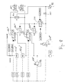
- the hydraulic system of Fig. 1 has a single internal combustion engine driven pump 16, in particular a Konstantpume 16, on. These Pump supplies both a coupling part (clutch actuation and Clutch cooling) as well as a transmission operating section 160p 'of the Hydraulic system.
- the pump is a suction filter 50 upstream and a Downstream of the pressure filter 20. You can either only a pressure filter or provide only a suction filter, depending on the sensitivity of the used Valves.
- a check valve 510p connected in parallel, so that despite clogged pressure filter still a Operation is possible, at the risk of the subsequent valves.
- pressure limiters 66 and 116 which provide a pressure on the output side of the pump 16 and the output side of the pressure control valves 106, 108 secure.
- the volume of oil draining through the damming valve 162p is supplied by a Volume flow control valve 22n through the oil cooler 152 for cooling in the Double clutch and / or back to the intake of the pump 16 directed, depending on the desired cooling oil volume flow.
- the return of the oil in the suction of the pump has the advantage that the pump when Suction of the oil is supported, which improves the pump filling level and the cavitation tendency is reduced. There may be situations in which it is desired, the oil flow provided by the pump all leading back into the suction area of the pump, leaving nothing to Coupling flows.
- the flow control valve 22n may be referred to as Two-way flow control valve with orifice plate to be designed in the bypass.
- a slider By the active operation of a slider, such as by magnetic force, can also set lower flow rates for cooling the clutch are considered to be due to the pressure difference across a metering orifice adjusting volume flow.
- an additional pressure relief valve between Volume flow control valve 22n and the oil cooler 152 are installed to to achieve an increased back pressure in the supply line to the clutch.
- the double-sided hydraulic pressure applied flow control valve 22n operates on the pressure balance principle.
- the Cooling oil line is the addressed orifice 500n, at the in Depending on the volume flow, a differential pressure drops.
- This Differential pressure which represents the instantaneous volume flow, becomes the two sides (control inputs) of the volume flow control valve 22n created.
- the pressure in front of the orifice 500n plus an adjustable Magnetic force becomes the pressure after the diaphragm plus a spring force compared.
- a damper 502n be arranged for a quick closing of the flow control valve 22n to provide in the event of a pressure increase and thus a Failure of clutch cooling can be prevented between the pump-side pressure tap and the spring force counteracting Control input advantageously a damper 502n be arranged.
- the Flow control valve can then quickly to a pressure increase respond, move in the closing direction and thus the outflow to Reduce the inlet side of the pump.
- Fig. 2a shows schematically a concrete embodiment of the flow control valve 22n in a convenient installation situation in the hydraulic system of Fig. 1.
- the guided for coupling cooling oil volume flow goes on Flow control valve over and the return to the input side the pump passes through the flow control valve 22n.
- a possibly provided further outlet of the flow control valve 22n is closed and will not be used.
- FIG. 2b shows another installation situation for now with 22n 'designated flow control valve, in which the cooling oil flow to Clutch passes through the valve 22n 'out.
- the valve 22n ' is thus in Series connected to the orifice plate 500n '.
- the control piston of the valve splits the inflowing medium flow in the direction of the coupling going Cooling oil volume flow and the inlet side of the pump or in the Reservoir 26 (the tank) returning recirculation flow on, in Dependence on the pressure drop at the orifice plate 500n 'and the current supply solenoid of the valve.
- a volume flow control based on an adjustable orifice comes into consideration.
- a via an electromagnet (solenoid) or a hydraulic Pressure translation controlled metering orifice can be used.
- Fig. 1 is a direct flow of the flow control valve according to Fig. 2b is possible as an alternative.
- An additional one Back pressure or resistance in the cooling oil line after the flow control valve is not necessary if a complete shutdown of the Cooling oil volume flow to the clutch is desired.
- volume flow control valves in Consider, in particular, a three-way flow control valve.
- a direct control via magnetic force or a with regard to the passage resistance adjustable orifice also a Design of the volume flow control valve as a pilot operated valve possible.
- the gearbox actuation takes place on the example used here four shift rails that shift gears 1 through 7 and R. Beeing confirmed the shift rails by eight single-acting cylinder (four for each partial transmission), each in pairs one of the shift rails assigned. These are cylinders 192-1-1 and 192-1-2; 192-2-1 and 192-2-2; 194-1-1 and 194-1-2 and 194-2-1 and 194-2-2, respectively.
- the optionally also be designated as a shift gate valve cylinder selector valves 520p, 522p are designed as hydraulically piloted 8/2-way valves, which are themselves controlled by the switching valve 524p.
- the two Cylinder selector valves 520p and 522p supply the supplied pressure oil in each case an associated cylinder pair, while the cylinder chambers of other cylinder pair are connected to the oil reservoir, ie in Essentially depressurized.
- the two cylinder selector valves is together upstream of a partial transmission selector valve 526p, which also as hydraulically pilot operated 8/2-way valve is executed.
- the partial transmission selector valve is driven by a switching valve 528p.
- the partial transmission selector valve 526p passes this from him, for example, as a gear selector valve markable valve 530p 'supplied pressure oil either the Cylinder selector valve 520p for operating the gear unit TG2 or the Cylinder selector valve 522p for actuating subtransmission TG1.
- the Gang dichlventil 530p ' is present as a proportional directional valve, more precisely than proportional 4/3-way valve executed. It is designed so that Move a respective shift rod in each case only one of the both single-acting cylinder is pressurized with pressure oil. The respectively another cylinder associated with the same shift rod is above the valve 530p 'to the tank.
- the gear selector valve 530p 'and the switching valve 528p are hydraulic actuatable Zuschaltventil upstream 531p. This serves that in the Driving operation, if not switched on the transmission, the oil supply of Valves for the transmission actuators is interrupted.
- the connection valve 531p is determined by the oil pressure set by the defrosting valve 162p driven.
- the opening pressure for the connection valve 531p can expediently be designed so that it has a certain value above the Pressure is due to the transmission of the maximum engine torque the clutch assemblies corresponding pressure.
- On the Zuschaltventil 531p can certainly be waived.
- An alternative is, for example, that the Gang Stammlventil 530p 'held in the locked position we, as long as no switching is required. This has the disadvantage of constant energization of the solenoid of the valve 530p '. Furthermore, the Valves 530p 'and 528p settle.
- the operation of the hydraulic circuit of Fig. 1 can for example, as follows. If the control unit sends a switching command, then the accumulation valve 162p is energized so far that the pressure on the maximum engine torque corresponding pressure increases. This has to As a consequence, the sequence valve 531p switches to flow. At the same time with the Bestromen the accumulation valve 162p when switching is also the Gear selector valve 530p 'energized so far that it is in the blocking position (second or middle position) moves. In this condition, the pressure connection of the Gear selector valve 530p 'pressure on. Depending on which gear is switched is to be, the gear selector valve is moved to position 1 or 3, the Switching valve 528p energized or not and the switching valve 524p energized or not. Voted on this, the operation of the Coupling arrangements by means of the control valves 106 and 108 in the engagement or disengagement senses.
- Double clutch 100 or for the actuation of the double clutch should the following are added.
- it is in the Double clutch 100 to a double clutch with two multi-plate clutch assemblies, those in Fig. 1 and Fig. 4 respectively by the hydraulic slave cylinder 102 or 104 are represented, the Actuation of the respective multi-disc clutch assembly in Ein Wegsinne serves. So it is to clutch arrangements of NORMALLY-OPEN type.
- the two hydraulic Slave cylinders 102 and 104 are each the 3/2-way pressure control valve 106 or assigned 108, via which the respective slave cylinder controlled with Pressure oil or pressure can be acted upon. These are the pressure control valves On the input side to the pressure oil supply of the pump assembly 10 and the Pressure oil pump 16 connected, on the input side of the Damming valve 162p.
- the dual clutch 100 is connected via a cooling oil circuit 150 of the Pump 16 via the accumulation valve 162p and the flow control valve Supplied with 22n provided cooling oil. Cooling oil through the double clutch 100 has flowed and has absorbed heat there, is in the oil reservoir 26 returned.
- the cooling oil circuit has upstream of the Double clutch 100, the oil cooler 152 on, for example, a Heat exchange with the ambient air or with a Cooling water circuit allows.
- the hydraulic system of Fig. 1 is connected to a in Fig. 1 in conjunction with Figs. 3 and 4 resulting pressure medium emergency supply for Double clutch 100 executed.
- Basic idea of the realized solution is that in case of power failure or failure of electronic Control the last active clutch arrangement K1 (104) or K2 (102) independent of the control valves 106 and 108 with a constant pressure is charged.
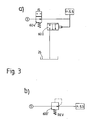
- the constant pressure can - to name just one example For example, be 5.5 bar and is the embodiment in the Variant according to Fig. 3a via a pressure reducing valve 600 is provided to the is connected between the pump 16 and the back pressure 162p and provides the emergency operating pressure or holding pressure controlled by 5.5 bar.
- the valve 600 is a valve with a hydraulic Control input for the feedback of the output side prevailing Hydraulic pressure.
- the discharge pressure of 5.5 bar is shown in Figs. 3 and 4 also designated p_5.5; the corresponding designations are used for Hint of pressure supply connections between different Components of the circuit part of FIG. 4 with the Pressure reducing valve.
- the pressure of 5.5 bar possibly for the control of pressure regulators as in 6 HP automatic gearboxes is often present anyway. In that regard, could in one Practical implementation of a corresponding pressure level anyway To be available.
- the valve 600 provide, namely, when the from Damping valve 162p in the non-energized state set pressure for the Coupling arrangement or the coupling arrangement side Hydraulic system section including the hydraulic slave cylinder is too high.
- the design of the hydraulic system so be that when not energized backwater 162p this while running Pump 116 sets a pressure of 20 bar.
- the back pressure 162p is a ⁇ ffnerventil, which opens when energized and thus the On the input side reduced by him prevailing pressure. Also in the Aufstaufall, So with less strong energization or lack of energizing the Solenoids of the accumulation valve 162p, but always flows essentially the Entire pumped by the pump 16 oil flow through the back pressure 162p towards the flow control valve 22n.
- the opening state of the Damming valve thus primarily determines only the input side of the control valves 106 and 108 or the connecting valve 531p prevailing pressure level, less or not at all the flow of oil through the damming 162p.
- an electric valve S5 (614) provided, which is energized in normal driving and in the energized Condition serving as a control pressure pressure, for example the Constant pressure, not let through, in the case of Brockbestromung but this Pressure as control pressure towards a respective control input of the Slider valve S1 or S2 lets through.
- connection between the runs electric switching valve S5 and the slide valve S1 or S2 via two further hydraulically controllable switching valves S4 (612) and S3 (610) to the switching of the switching valve S1 or S2 in Emergency supply condition depending on two other conditions.
- the slide valve of the slide valve S3 (610) is from both sides with the acting on the hydraulic slave cylinder actuating pressures acts and switches in the case of emergency supply from the Pressure Reducing Valve 600 provided either constant pressure in the direction to the slide valve S1, if previously on the hydraulic cylinder 104 of the greater actuation pressure worked, so the clutch assembly K1 (104) alone or more strongly engaged, or towards the spool valve S2, if previously acting on the hydraulic slave cylinder 102 Hydraulic pressure greater and accordingly the clutch assembly K2 (102) alone or more strongly engaged. It is guaranteed that the before the occurrence of a fault (especially power failure) last active Coupling arrangement on the slide valve S1 and slide valve S2 on the constant pressure is switched. Thus, in the last current gear safely continue until the first stop.
- the slide valve S4 is from both sides with a before and after a shutter 602 in the cooling oil supply line in the direction of Double clutch removed hydraulic pressure, so with one at this Aperture sloping differential pressure, applied.
- This differential pressure is a measure of the cooling oil volume flow in the direction of the double clutch 100th
- the cooling oil volume flow in turn represents the momentary Operating speed of the pump 16 and thus the speed of the drive unit (of the internal combustion engine) 12. In the case of a constant pump is the Oil flow proportional to the engine speed.
- the diaphragm and the slider S4 are in the illustrated embodiment now designed so that the difference between the pressure in front of the aperture (Pressure p_v_Blende) and after the aperture (pressure p_n_Blende) the Slider valve S4 below a threshold engine speed, for example the idle speed, so switches that serving as the control pressure Constant pressure from the switching valve S5 not to the slide valve S3 and thus to none of the two slide valves S1 and S2 is allowed to pass.
- a threshold engine speed for example the idle speed
- the pressure control valves 108 and 106 are designed and arranged to withstand power failure connect their working connection with the tank connection. This builds up the pressure in the relevant hydraulic slave cylinder in the direction of Tank off and it will be the traction on the concerned Coupling arrangement interrupted. This measure will reliably stalling the engine when it reaches the threshold or Limit speed (about the idle speed) prevented.
- the proposed design of the pressure medium emergency supply allows on the one hand an emergency operation, but without the risk that is strangled by the closed clutch of the internal combustion engine, which would lead to usually provided steering and Brake assistance of the motor vehicle fails, which is extremely safety-critical would be.
- the Idling speed is also a different critical engine speed than threshold or limit speed may be provided, the falling below the Opening the relevant clutch assembly does not lead to the engine stall and thus the ancillaries not to a halt or to avoid other operating and vehicle conditions.
- the slide valve S3 may have a detent, so that this remains in the last position taken and the constant pressure only in the direction of the slide valve S1 or S2 of the last active Can send coupling arrangement.
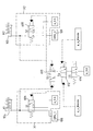
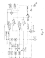
- the hydraulic system of FIG. 5 essentially corresponds to that Figs. 1, 3 and 4 devoted hydraulic system, namely the variant according to FIG. 3b.
- the valve S1, designated 606, labeled 608 Valve S2, the valve S3 labeled 610, the valve designated 612 S4 and the valve S5 labeled 614 are directly in the schematic plotted in association with the pressure control valves 106 and 108, the Change-over valve 512p and the hydraulic slave cylinder 102 and 104.
- the pressure reducing valve 600 of FIG. 3a is the Pressure reducing valve 600 'and provided by a corresponding Switch symbol represents drawn.
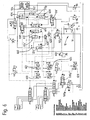
- Fig. 6 differs from the embodiment of FIG. 5 in that now with 108 "and 106" designated pressure control valves, which now with 162p “designated back pressure valve, now with 22n” designated Flow control valve and now with 530 "designated gear selector valve 530p "are designed as pilot operated valves, which means that the respective valve slide is no longer actuated by a magnetic force, but via a control pressure.
- the respective control pressure can via a associated pilot valve 620, 622, 624, 626 and 628 set become.
- pilot valves can, for example, cost as Seat valves be executed.
- These pilot valves are over Magnets driven, but these can be significantly smaller than at a directly controlled valve.
- the design of the pilot valves as Poppet valves are also advantageous insofar as they are less Dirt sensitive are as slide valves.
- pilot-operated valve arrangement is in particular that easier on the pilot pressure a higher force on the Successor pusher can be produced as having a magnet directly the slide is actuated.
- the pilot valves 620 to 628 require one lower pressure than the system pressure, e.g. also for the pressure medium emergency supply used constant pressure of, for example, 5.5 bar. This pressure is adjusted by the reducing valve 600 '.
- On-off valve 531p not as hydraulically operated, but as electric operated valve, in deviation from the illustration in Fig. 1, 5 and 6.
- the embodiment of Fig. 6 is still different in one another point of the embodiment of FIGS. 1 to 4 and of Embodiment of Fig. 5.
- the now with 614 "designated switching valve S5 is now not as electrically controlled, but as a hydraulic controlled valve executed.
- the switching valve S5 are two Assigned changeover valves WV1 and WV2, which are also available with 630 "or 632" are designated.
- the shuttle valve WV1 or 632 "leaves the respective larger of the pressure control valves 106 “and 108" supplied Pilot pressure to shuttle valve WV2 or 630 "through the largest of the supplied from the shuttle valve WV1 pilot pressure and the pilot pressure supplied to the flow control valve 22n “ to the control input of the switching valve S4 or 614 " Driving operation, if the electrical power supply is guaranteed and the electronics are working properly, so is always a sufficient large control pressure at the control input of the switching valve S5, so that the valve spool against the restoring force of a return spring in the Supply of the constant pressure of, for example, 5.5 bar to the slide valve S4 or 612 is interrupted.
- the electrically controllable valve 614 '''simultaneously serves as a changeover valve, which brings in the case of power failure by the pressure reducing valve 600''' reduced oil pressure via the check valve 640 and the switching valve 512p directly to the clutch assembly, which was last applied to higher pressure.
- the respective tank connection of the two pressure control / regulating valves 106 ''',108''' is blocked by the two hydraulically actuated changeover valves 606 '"and 608"'.
- valve 612 closes and the two changeover valves 606 '''and608''' remain open, so that the tank line is released to the couplings in the event of a fault.
- An increase in the engine speed can, with appropriate design of the valve 612, cause the valve to reopen due to sufficient differential pressure at the metering orifice, thereby closing the tank ports of the two pressure control / regulating valves 106 ''',108''' and thus a restart is possible.
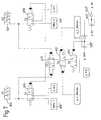
- FIG. 9 is opposite Fig.8 instead of an electrically controlled valve arranged the hydraulically controlled valve 614 b.
- the activation of the hydraulically controlled valve 614 b takes place as shown in FIG. 6 by means of two shuttle valves 630 "and 632".
- the hydraulically controlled valve 614 b continues to serve as in Fig.8 as a switching valve, which at Power failure of the CE pressure regulator opens and the reduced pressure to the Clutch arrangements unlocked.
- the two pressure control / regulating valves 106b, 108b are not blocked or bypassed during emergency driving operation of the vehicle, but that the two pressure controls / Control valves 106b, 108b have a further control port for the provided by the pressure reducing valve 600 "oil pressure at which rests in emergency driving the reduced pressure and a defined clutch pressure, which is not adjustable adjusts.
- the hydraulically controlled valve 614b on which in normal driving the larger of the two pilot pressures for the two pressure control / regulating valves 106b, 108b is applied, and which is thereby locked opens automatically in case of power failure at the pressure plates and sets the reduced pressure by means of the selector valve 610 to the pressure control / regulating valves 106b, 108b, which has last applied the higher pressure, which has automatically adjusted the selector valve 610 accordingly.
- the hydraulically controlled valve 614b is preceded by the valve 612b, which is opened at the applied pilot pressure against the restoring force of the spring.
- the pressure applied in front of the metering orifice B abuts the valve 612b in the opening direction and serves to keep the valve 612b in the open position in the event of failure of the pilot pressures.
- the valve 612b is closed by the restoring force of the spring, so that the applied pressure on the clutch assemblies is reduced, whereby the power circuit is released and stalling of the engine is prevented.
- the valve 612b still has a pressure which can be shifted by the RVV in the locked position, which blocks the valve 612b when the reverse gear is engaged.
- the valve RVV opens when engaging the reverse gear and leaves the reduced pressure of 5.5 bar act on the spring chamber of the valve 612b whereby this closes and thus the remindfahrfahr congress the emergency drive function is prevented.
Landscapes
- Engineering & Computer Science (AREA)
- General Engineering & Computer Science (AREA)
- Mechanical Engineering (AREA)
- Physics & Mathematics (AREA)
- Fluid Mechanics (AREA)
- Chemical & Material Sciences (AREA)
- Analytical Chemistry (AREA)
- Hydraulic Clutches, Magnetic Clutches, Fluid Clutches, And Fluid Joints (AREA)
- Valves And Accessory Devices For Braking Systems (AREA)
Applications Claiming Priority (2)
| Application Number | Priority Date | Filing Date | Title |
|---|---|---|---|
| DE10347073A DE10347073A1 (de) | 2003-10-10 | 2003-10-10 | Druckmedium-Notversorgnung für ein Kupplungssystem und ein die Druckmedium-Notversorgung aufweisender Kraftfahrzeug-Antriebsstrang |
| DE10347073 | 2003-10-10 |
Publications (2)
| Publication Number | Publication Date |
|---|---|
| EP1522754A1 true EP1522754A1 (fr) | 2005-04-13 |
| EP1522754B1 EP1522754B1 (fr) | 2006-12-20 |
Family
ID=34306349
Family Applications (1)
| Application Number | Title | Priority Date | Filing Date |
|---|---|---|---|
| EP04024024A Not-in-force EP1522754B1 (fr) | 2003-10-10 | 2004-10-08 | Alimentation en fluide sous pression pour système d'embrayage et train de propulsion pour vehicules avec cette alimentation en fluide sous pression. |
Country Status (3)
| Country | Link |
|---|---|
| EP (1) | EP1522754B1 (fr) |
| AT (1) | ATE348963T1 (fr) |
| DE (2) | DE10347073A1 (fr) |
Cited By (12)
| Publication number | Priority date | Publication date | Assignee | Title |
|---|---|---|---|---|
| WO2005106291A3 (fr) * | 2004-04-27 | 2006-03-30 | Zahnradfabrik Friedrichshafen | Agencement de soupape de commande pour la commande d'un embrayage de demarrage d'une boite de vitesses automatique |
| WO2006119848A1 (fr) * | 2005-05-10 | 2006-11-16 | Zf Friedrichshafen Ag | Ensemble transmission d'un vehicule a moteur et procede de commande d'un embrayage moteur automatique |
| WO2007045401A1 (fr) * | 2005-10-21 | 2007-04-26 | Zf Friedrichshafen Ag | Ensemble soupape de commande pour la commande d'un embrayage de demarrage d'une boite de vitesses automatique |
| DE102005050489A1 (de) * | 2005-10-21 | 2007-04-26 | Zf Friedrichshafen Ag | Steuerungsventilanordnung zur Steuerung einer Anfahrkupplung eines Automatgetriebes |
| DE102005050494A1 (de) * | 2005-10-21 | 2007-04-26 | Zf Friedrichshafen Ag | Steuerungsventilanordnung zur Steuerung einer Anfahrkupplung eines Automatgetriebes |
| DE102006035134A1 (de) * | 2006-07-29 | 2008-01-31 | Zf Friedrichshafen Ag | Kupplungssystem |
| DE102006046710A1 (de) * | 2006-10-02 | 2008-04-03 | Zf Friedrichshafen Ag | Druckmittelbetätigbare Steuerungsvorrichtung eines automatisierten Stufenschaltgetriebes |
| WO2008049735A1 (fr) * | 2006-10-24 | 2008-05-02 | Zf Friedrichshafen Ag | Dispositif de commande hydraulique d'une boîte de vitesses automatisée à rapport étagés |
| DE102007055811A1 (de) * | 2007-12-14 | 2009-06-25 | Zf Friedrichshafen Ag | Hydraulische Steuerungsanordnung für eine hydraulisch betätigte Reibungskupplung |
| WO2016156572A1 (fr) * | 2015-04-02 | 2016-10-06 | Punch Powertrain N.V. | Soupape de vidange |
| CN107199915A (zh) * | 2017-05-25 | 2017-09-26 | 福建中青汽车技术有限公司 | 一种纯电动车辆换挡系统 |
| CN108291588A (zh) * | 2015-11-26 | 2018-07-17 | 五十铃自动车株式会社 | 工作油控制装置 |
Families Citing this family (8)
| Publication number | Priority date | Publication date | Assignee | Title |
|---|---|---|---|---|
| DE102005058779A1 (de) * | 2005-12-09 | 2007-06-14 | Zf Friedrichshafen Ag | Vorrichtung zum Betätigen von Schaltelementen einer Getriebeeinrichtung |
| DE102006008169B4 (de) * | 2006-02-22 | 2015-05-28 | Volkswagen Ag | Vorrichtung zur Steuerung und/oder Regelung der Kupplungskühlung eines Getriebes eines Kraftfahrzeuges |
| WO2008064630A1 (fr) * | 2006-11-27 | 2008-06-05 | Luk Lamellen Und Kupplungsbau Beteiligungs Kg | Système hydraulique pour un véhicule |
| DE102007032964A1 (de) * | 2007-07-16 | 2009-01-22 | Knorr-Bremse Systeme für Nutzfahrzeuge GmbH | Vorrichtung zum Stellen eines Aktuators |
| DE102007037589B4 (de) * | 2007-08-09 | 2019-03-28 | Conti Temic Microelectronic Gmbh | Verfahren zur Steuerung einer Doppelkupplung, insbesondere der Doppelkupplung eines Doppelkupplungsgetriebes |
| DE102009027070A1 (de) | 2009-06-22 | 2010-12-23 | Zf Friedrichshafen Ag | Ansteuerschaltung für einen pneumatischen oder hydraulischen Aktuator |
| DE102015225323A1 (de) * | 2015-12-15 | 2017-06-22 | Schaeffler Technologies AG & Co. KG | Ventilblock für ein Hydrauliksystem eines Doppelkupplungsgetriebes |
| DE102016205574A1 (de) * | 2016-04-05 | 2017-10-05 | Robert Bosch Gmbh | Ventilbaugruppe mit selbstkalibrierendem Drucksensor |
Citations (2)
| Publication number | Priority date | Publication date | Assignee | Title |
|---|---|---|---|---|
| DE19856297A1 (de) * | 1998-12-07 | 2000-06-15 | Bosch Gmbh Robert | Hydrauliknotsteuerung für eine zwischen einem Verbrennungsmotor und einem Getriebe angeordnete Kupplung |
| DE10150598A1 (de) * | 2001-10-12 | 2003-04-24 | Zf Sachs Ag | Kupplungssystem mit wenigstens einer druckmittelbetätigbaren, für einen Betrieb unter Einwirkung eines Betriebsmediums vorgesehenen Kupplungsanordnung |
-
2003
- 2003-10-10 DE DE10347073A patent/DE10347073A1/de not_active Ceased
-
2004
- 2004-10-08 AT AT04024024T patent/ATE348963T1/de active
- 2004-10-08 DE DE502004002361T patent/DE502004002361D1/de active Active
- 2004-10-08 EP EP04024024A patent/EP1522754B1/fr not_active Not-in-force
Patent Citations (2)
| Publication number | Priority date | Publication date | Assignee | Title |
|---|---|---|---|---|
| DE19856297A1 (de) * | 1998-12-07 | 2000-06-15 | Bosch Gmbh Robert | Hydrauliknotsteuerung für eine zwischen einem Verbrennungsmotor und einem Getriebe angeordnete Kupplung |
| DE10150598A1 (de) * | 2001-10-12 | 2003-04-24 | Zf Sachs Ag | Kupplungssystem mit wenigstens einer druckmittelbetätigbaren, für einen Betrieb unter Einwirkung eines Betriebsmediums vorgesehenen Kupplungsanordnung |
Cited By (31)
| Publication number | Priority date | Publication date | Assignee | Title |
|---|---|---|---|---|
| US7736270B2 (en) | 2004-04-27 | 2010-06-15 | Zf Friedrichshafen Ag | Control valve arrangement for controlling a start clutch of an automatic gearbox |
| WO2005106291A3 (fr) * | 2004-04-27 | 2006-03-30 | Zahnradfabrik Friedrichshafen | Agencement de soupape de commande pour la commande d'un embrayage de demarrage d'une boite de vitesses automatique |
| WO2006119848A1 (fr) * | 2005-05-10 | 2006-11-16 | Zf Friedrichshafen Ag | Ensemble transmission d'un vehicule a moteur et procede de commande d'un embrayage moteur automatique |
| WO2007045401A1 (fr) * | 2005-10-21 | 2007-04-26 | Zf Friedrichshafen Ag | Ensemble soupape de commande pour la commande d'un embrayage de demarrage d'une boite de vitesses automatique |
| DE102005050489A1 (de) * | 2005-10-21 | 2007-04-26 | Zf Friedrichshafen Ag | Steuerungsventilanordnung zur Steuerung einer Anfahrkupplung eines Automatgetriebes |
| WO2007045400A1 (fr) * | 2005-10-21 | 2007-04-26 | Zf Friedrichshafen Ag | Dispositif de soupapes de commande pour la commande d'un embrayage de demarrage d'une boite de vitesses automatique |
| DE102005050494A1 (de) * | 2005-10-21 | 2007-04-26 | Zf Friedrichshafen Ag | Steuerungsventilanordnung zur Steuerung einer Anfahrkupplung eines Automatgetriebes |
| DE102005050493A1 (de) * | 2005-10-21 | 2007-04-26 | Zf Friedrichshafen Ag | Steuerungsventilanordnung zur Steuerung einer Anfahrkupplung eines Automatgetriebes |
| CN101287934B (zh) * | 2005-10-21 | 2012-01-11 | 腓特烈斯港齿轮工厂股份公司 | 用于控制自动变速器的起动离合器的控制阀装置 |
| US7780572B2 (en) | 2005-10-21 | 2010-08-24 | Zf Friedrichshafen Ag | Control valve arrangement for controlling a starting clutch of an automatic transmission |
| US7771317B2 (en) | 2005-10-21 | 2010-08-10 | Zf Friedrichshafen Ag | Control valve assembly for controlling a starting clutch of an automatic transmission |
| DE102006035134A1 (de) * | 2006-07-29 | 2008-01-31 | Zf Friedrichshafen Ag | Kupplungssystem |
| US8187148B2 (en) | 2006-07-29 | 2012-05-29 | Zf Friedrichshafen Ag | Clutch system |
| RU2450179C2 (ru) * | 2006-07-29 | 2012-05-10 | Цф Фридрихсхафен Аг | Система сцепления |
| WO2008015061A1 (fr) * | 2006-07-29 | 2008-02-07 | Zf Friedrichshafen Ag | Système d'accouplement |
| CN101490435B (zh) * | 2006-07-29 | 2011-04-13 | Zf腓德烈斯哈芬股份公司 | 离合器系统 |
| DE102006046710A1 (de) * | 2006-10-02 | 2008-04-03 | Zf Friedrichshafen Ag | Druckmittelbetätigbare Steuerungsvorrichtung eines automatisierten Stufenschaltgetriebes |
| US8167105B2 (en) | 2006-10-02 | 2012-05-01 | Zf Friedrichshafen Ag | Pressure medium-actuated control device of an automated step-by-step variable speed transmission |
| US8147380B2 (en) | 2006-10-24 | 2012-04-03 | Zf Friedrichshafen Ag | Hydraulic control apparatus of an automated multi-step change-speed gearbox |
| WO2008049735A1 (fr) * | 2006-10-24 | 2008-05-02 | Zf Friedrichshafen Ag | Dispositif de commande hydraulique d'une boîte de vitesses automatisée à rapport étagés |
| DE102007055811A1 (de) * | 2007-12-14 | 2009-06-25 | Zf Friedrichshafen Ag | Hydraulische Steuerungsanordnung für eine hydraulisch betätigte Reibungskupplung |
| BE1023071B1 (nl) * | 2015-04-02 | 2016-11-16 | Punch Powertrain Nv | Afvoerventiel |
| WO2016156572A1 (fr) * | 2015-04-02 | 2016-10-06 | Punch Powertrain N.V. | Soupape de vidange |
| CN107532707A (zh) * | 2015-04-02 | 2018-01-02 | 邦奇动力有限责任公司 | 排泄阀 |
| US10371216B2 (en) | 2015-04-02 | 2019-08-06 | Punch Powertrain N.V. | Drain valve |
| CN107532707B (zh) * | 2015-04-02 | 2019-12-10 | 邦奇动力有限责任公司 | 车辆变速器的液压系统及控制其中压力的方法 |
| CN108291588A (zh) * | 2015-11-26 | 2018-07-17 | 五十铃自动车株式会社 | 工作油控制装置 |
| EP3382225A4 (fr) * | 2015-11-26 | 2019-06-26 | Isuzu Motors, Ltd. | Dispositif de commande d'huile hydraulique |
| US10837503B2 (en) | 2015-11-26 | 2020-11-17 | Isuzu Motors Limited | Hydraulic-oil control device |
| CN107199915A (zh) * | 2017-05-25 | 2017-09-26 | 福建中青汽车技术有限公司 | 一种纯电动车辆换挡系统 |
| CN107199915B (zh) * | 2017-05-25 | 2023-05-02 | 福建中青汽车技术有限公司 | 一种纯电动车辆换挡系统 |
Also Published As
| Publication number | Publication date |
|---|---|
| DE10347073A1 (de) | 2005-05-04 |
| DE502004002361D1 (de) | 2007-02-01 |
| EP1522754B1 (fr) | 2006-12-20 |
| ATE348963T1 (de) | 2007-01-15 |
Similar Documents
| Publication | Publication Date | Title |
|---|---|---|
| EP1522754B1 (fr) | Alimentation en fluide sous pression pour système d'embrayage et train de propulsion pour vehicules avec cette alimentation en fluide sous pression. | |
| EP1420185B2 (fr) | Transmission pour véhicule automobile comprenant une pompe d'alimentation d'un système d'embrayage en fluide sous pression | |
| EP1420186B1 (fr) | Transmission pour véhicule automobile comprenant une pompe d'alimentation d'un système d'embrayage en fluide sous pression | |
| EP2520832B1 (fr) | Engrenage à couplage | |
| EP2705279B1 (fr) | Circuit hydraulique et son procédé de fonctionnement | |
| DE112007002509B4 (de) | Hydraulische Steuerung für ein Doppelkupplungsgetriebe | |
| EP2705280B1 (fr) | Procédé pour faire fonctionner une boîte de vitesses à embrayage et boîte de vitesses à embrayage correspondante | |
| EP1517059B1 (fr) | Engrenage à double embrayage avec fonction de maintien de position | |
| EP2609348B1 (fr) | Commande hydraulique pour une transmission automatique d'un véhicule automobile | |
| EP3227587A2 (fr) | Ensemble frein de stationnement | |
| DE10155050A1 (de) | Kraftfahrzeug-Antriebsstrang mit wenigstens einer unter Vermittlung von Druckmedium betätigbaren und unter Einwirkung eines Betriebsmediums laufenden Kupplungsanordnung und einem unter Vermittlung von Druckmedium betätigbaren Getriebe sowie entsprechendes Kupplungssystem | |
| WO2012104046A1 (fr) | Dispositif de réglage hydraulique | |
| DE102011100845B4 (de) | Kupplungsgetriebe, insbesondere Doppelkupplungsgetriebe, mit einem Druckspeicher | |
| EP2739882A1 (fr) | Commande hydraulique pour une transmission automatique d'un véhicule automobile | |
| WO2013017202A1 (fr) | Commande hydraulique pour une transmission automatique d'un véhicule automobile | |
| DE102011100862B4 (de) | Doppelkupplungsgetriebe | |
| DE102016206561B4 (de) | Verfahren zum Betreiben einer Parksperreneinrichtung mittels eines Hydrauliksystems | |
| DE102011100809B4 (de) | Kupplungsgetriebe mit Sicherheitsventilanordnung | |
| DE102011100838A1 (de) | Doppelkupplungsgetriebe | |
| DE102011100799B4 (de) | Doppelkupplungsgetriebe, Verfahren zum Betreiben | |
| DE102016206565B4 (de) | Verfahren zum Betreiben einer Parksperreneinrichtung mittels eines Hydrauliksystems | |
| DE102011100837A1 (de) | Kupplungsgetriebe, Verfahren zum Betreiben eines Kupplungsgetriebes | |
| DE102011100810B4 (de) | Doppelkupplungsgetriebe, Verfahren zum Betreiben | |
| DE102010035589A1 (de) | Steuerungsvorrichtung eines mehrgängigen Getriebes | |
| DE102011100807B4 (de) | Kupplungsgetriebe, insbesondere Doppelkupplungsgetriebe |
Legal Events
| Date | Code | Title | Description |
|---|---|---|---|
| PUAI | Public reference made under article 153(3) epc to a published international application that has entered the european phase |
Free format text: ORIGINAL CODE: 0009012 |
|
| 17P | Request for examination filed |
Effective date: 20050216 |
|
| AK | Designated contracting states |
Kind code of ref document: A1 Designated state(s): AT BE BG CH CY CZ DE DK EE ES FI FR GB GR HU IE IT LI LU MC NL PL PT RO SE SI SK TR |
|
| AX | Request for extension of the european patent |
Extension state: AL HR LT LV MK |
|
| AKX | Designation fees paid |
Designated state(s): AT BE BG CH CY CZ DE DK EE ES FI FR GB GR HU IE IT LI LU MC NL PL PT RO SE SI SK TR |
|
| GRAP | Despatch of communication of intention to grant a patent |
Free format text: ORIGINAL CODE: EPIDOSNIGR1 |
|
| GRAS | Grant fee paid |
Free format text: ORIGINAL CODE: EPIDOSNIGR3 |
|
| GRAA | (expected) grant |
Free format text: ORIGINAL CODE: 0009210 |
|
| RIN1 | Information on inventor provided before grant (corrected) |
Inventor name: TOEGEL, MATTHIAS Inventor name: KRAUS, PAUL Inventor name: STEINER, EDUARD |
|
| AK | Designated contracting states |
Kind code of ref document: B1 Designated state(s): AT BE BG CH CY CZ DE DK EE ES FI FR GB GR HU IE IT LI LU MC NL PL PT RO SE SI SK TR |
|
| PG25 | Lapsed in a contracting state [announced via postgrant information from national office to epo] |
Ref country code: CZ Free format text: LAPSE BECAUSE OF FAILURE TO SUBMIT A TRANSLATION OF THE DESCRIPTION OR TO PAY THE FEE WITHIN THE PRESCRIBED TIME-LIMIT Effective date: 20061220 Ref country code: RO Free format text: LAPSE BECAUSE OF FAILURE TO SUBMIT A TRANSLATION OF THE DESCRIPTION OR TO PAY THE FEE WITHIN THE PRESCRIBED TIME-LIMIT Effective date: 20061220 Ref country code: DK Free format text: LAPSE BECAUSE OF FAILURE TO SUBMIT A TRANSLATION OF THE DESCRIPTION OR TO PAY THE FEE WITHIN THE PRESCRIBED TIME-LIMIT Effective date: 20061220 Ref country code: SI Free format text: LAPSE BECAUSE OF FAILURE TO SUBMIT A TRANSLATION OF THE DESCRIPTION OR TO PAY THE FEE WITHIN THE PRESCRIBED TIME-LIMIT Effective date: 20061220 Ref country code: FI Free format text: LAPSE BECAUSE OF FAILURE TO SUBMIT A TRANSLATION OF THE DESCRIPTION OR TO PAY THE FEE WITHIN THE PRESCRIBED TIME-LIMIT Effective date: 20061220 Ref country code: SK Free format text: LAPSE BECAUSE OF FAILURE TO SUBMIT A TRANSLATION OF THE DESCRIPTION OR TO PAY THE FEE WITHIN THE PRESCRIBED TIME-LIMIT Effective date: 20061220 Ref country code: IE Free format text: LAPSE BECAUSE OF FAILURE TO SUBMIT A TRANSLATION OF THE DESCRIPTION OR TO PAY THE FEE WITHIN THE PRESCRIBED TIME-LIMIT Effective date: 20061220 Ref country code: PL Free format text: LAPSE BECAUSE OF FAILURE TO SUBMIT A TRANSLATION OF THE DESCRIPTION OR TO PAY THE FEE WITHIN THE PRESCRIBED TIME-LIMIT Effective date: 20061220 |
|
| REG | Reference to a national code |
Ref country code: GB Ref legal event code: FG4D Free format text: NOT ENGLISH |
|
| REG | Reference to a national code |
Ref country code: CH Ref legal event code: EP |
|
| REF | Corresponds to: |
Ref document number: 502004002361 Country of ref document: DE Date of ref document: 20070201 Kind code of ref document: P |
|
| REG | Reference to a national code |
Ref country code: IE Ref legal event code: FG4D Free format text: LANGUAGE OF EP DOCUMENT: GERMAN |
|
| PG25 | Lapsed in a contracting state [announced via postgrant information from national office to epo] |
Ref country code: SE Free format text: LAPSE BECAUSE OF FAILURE TO SUBMIT A TRANSLATION OF THE DESCRIPTION OR TO PAY THE FEE WITHIN THE PRESCRIBED TIME-LIMIT Effective date: 20070320 Ref country code: BG Free format text: LAPSE BECAUSE OF FAILURE TO SUBMIT A TRANSLATION OF THE DESCRIPTION OR TO PAY THE FEE WITHIN THE PRESCRIBED TIME-LIMIT Effective date: 20070320 |
|
| PG25 | Lapsed in a contracting state [announced via postgrant information from national office to epo] |
Ref country code: ES Free format text: LAPSE BECAUSE OF FAILURE TO SUBMIT A TRANSLATION OF THE DESCRIPTION OR TO PAY THE FEE WITHIN THE PRESCRIBED TIME-LIMIT Effective date: 20070331 |
|
| PG25 | Lapsed in a contracting state [announced via postgrant information from national office to epo] |
Ref country code: PT Free format text: LAPSE BECAUSE OF FAILURE TO SUBMIT A TRANSLATION OF THE DESCRIPTION OR TO PAY THE FEE WITHIN THE PRESCRIBED TIME-LIMIT Effective date: 20070424 |
|
| ET | Fr: translation filed | ||
| PLBE | No opposition filed within time limit |
Free format text: ORIGINAL CODE: 0009261 |
|
| STAA | Information on the status of an ep patent application or granted ep patent |
Free format text: STATUS: NO OPPOSITION FILED WITHIN TIME LIMIT |
|
| 26N | No opposition filed |
Effective date: 20070921 |
|
| PG25 | Lapsed in a contracting state [announced via postgrant information from national office to epo] |
Ref country code: GR Free format text: LAPSE BECAUSE OF FAILURE TO SUBMIT A TRANSLATION OF THE DESCRIPTION OR TO PAY THE FEE WITHIN THE PRESCRIBED TIME-LIMIT Effective date: 20070321 |
|
| PG25 | Lapsed in a contracting state [announced via postgrant information from national office to epo] |
Ref country code: MC Free format text: LAPSE BECAUSE OF NON-PAYMENT OF DUE FEES Effective date: 20071031 |
|
| PG25 | Lapsed in a contracting state [announced via postgrant information from national office to epo] |
Ref country code: EE Free format text: LAPSE BECAUSE OF FAILURE TO SUBMIT A TRANSLATION OF THE DESCRIPTION OR TO PAY THE FEE WITHIN THE PRESCRIBED TIME-LIMIT Effective date: 20061220 |
|
| PG25 | Lapsed in a contracting state [announced via postgrant information from national office to epo] |
Ref country code: CY Free format text: LAPSE BECAUSE OF FAILURE TO SUBMIT A TRANSLATION OF THE DESCRIPTION OR TO PAY THE FEE WITHIN THE PRESCRIBED TIME-LIMIT Effective date: 20061220 |
|
| PG25 | Lapsed in a contracting state [announced via postgrant information from national office to epo] |
Ref country code: HU Free format text: LAPSE BECAUSE OF FAILURE TO SUBMIT A TRANSLATION OF THE DESCRIPTION OR TO PAY THE FEE WITHIN THE PRESCRIBED TIME-LIMIT Effective date: 20070621 Ref country code: TR Free format text: LAPSE BECAUSE OF FAILURE TO SUBMIT A TRANSLATION OF THE DESCRIPTION OR TO PAY THE FEE WITHIN THE PRESCRIBED TIME-LIMIT Effective date: 20061220 |
|
| PGFP | Annual fee paid to national office [announced via postgrant information from national office to epo] |
Ref country code: LU Payment date: 20141013 Year of fee payment: 11 |
|
| PGFP | Annual fee paid to national office [announced via postgrant information from national office to epo] |
Ref country code: DE Payment date: 20140930 Year of fee payment: 11 Ref country code: FR Payment date: 20141008 Year of fee payment: 11 Ref country code: GB Payment date: 20141008 Year of fee payment: 11 Ref country code: CH Payment date: 20141014 Year of fee payment: 11 |
|
| PGFP | Annual fee paid to national office [announced via postgrant information from national office to epo] |
Ref country code: NL Payment date: 20141010 Year of fee payment: 11 Ref country code: AT Payment date: 20140925 Year of fee payment: 11 |
|
| PGFP | Annual fee paid to national office [announced via postgrant information from national office to epo] |
Ref country code: IT Payment date: 20141010 Year of fee payment: 11 |
|
| PGFP | Annual fee paid to national office [announced via postgrant information from national office to epo] |
Ref country code: BE Payment date: 20141013 Year of fee payment: 11 |
|
| REG | Reference to a national code |
Ref country code: DE Ref legal event code: R119 Ref document number: 502004002361 Country of ref document: DE |
|
| PG25 | Lapsed in a contracting state [announced via postgrant information from national office to epo] |
Ref country code: LU Free format text: LAPSE BECAUSE OF NON-PAYMENT OF DUE FEES Effective date: 20151008 |
|
| REG | Reference to a national code |
Ref country code: CH Ref legal event code: PL |
|
| REG | Reference to a national code |
Ref country code: AT Ref legal event code: MM01 Ref document number: 348963 Country of ref document: AT Kind code of ref document: T Effective date: 20151008 |
|
| GBPC | Gb: european patent ceased through non-payment of renewal fee |
Effective date: 20151008 |
|
| REG | Reference to a national code |
Ref country code: NL Ref legal event code: MM Effective date: 20151101 |
|
| PG25 | Lapsed in a contracting state [announced via postgrant information from national office to epo] |
Ref country code: GB Free format text: LAPSE BECAUSE OF NON-PAYMENT OF DUE FEES Effective date: 20151008 Ref country code: IT Free format text: LAPSE BECAUSE OF NON-PAYMENT OF DUE FEES Effective date: 20151008 Ref country code: LI Free format text: LAPSE BECAUSE OF NON-PAYMENT OF DUE FEES Effective date: 20151031 Ref country code: DE Free format text: LAPSE BECAUSE OF NON-PAYMENT OF DUE FEES Effective date: 20160503 Ref country code: CH Free format text: LAPSE BECAUSE OF NON-PAYMENT OF DUE FEES Effective date: 20151031 |
|
| REG | Reference to a national code |
Ref country code: FR Ref legal event code: ST Effective date: 20160630 |
|
| PG25 | Lapsed in a contracting state [announced via postgrant information from national office to epo] |
Ref country code: FR Free format text: LAPSE BECAUSE OF NON-PAYMENT OF DUE FEES Effective date: 20151102 Ref country code: NL Free format text: LAPSE BECAUSE OF NON-PAYMENT OF DUE FEES Effective date: 20151101 Ref country code: AT Free format text: LAPSE BECAUSE OF NON-PAYMENT OF DUE FEES Effective date: 20151008 |
|
| PG25 | Lapsed in a contracting state [announced via postgrant information from national office to epo] |
Ref country code: BE Free format text: LAPSE BECAUSE OF NON-PAYMENT OF DUE FEES Effective date: 20151031 |