EP2151290B1 - Equipment for molding mold with molding flask, and method for molding mold with molding flask - Google Patents
Equipment for molding mold with molding flask, and method for molding mold with molding flask Download PDFInfo
- Publication number
- EP2151290B1 EP2151290B1 EP08752782.6A EP08752782A EP2151290B1 EP 2151290 B1 EP2151290 B1 EP 2151290B1 EP 08752782 A EP08752782 A EP 08752782A EP 2151290 B1 EP2151290 B1 EP 2151290B1
- Authority
- EP
- European Patent Office
- Prior art keywords
- molding
- mold
- flask
- sand
- squeezing
- Prior art date
- Legal status (The legal status is an assumption and is not a legal conclusion. Google has not performed a legal analysis and makes no representation as to the accuracy of the status listed.)
- Active
Links
- 238000000465 moulding Methods 0.000 title claims description 215
- 238000000034 method Methods 0.000 title claims description 24
- 239000003110 molding sand Substances 0.000 claims description 131
- 239000004576 sand Substances 0.000 claims description 40
- 238000007664 blowing Methods 0.000 claims description 9
- 238000009423 ventilation Methods 0.000 claims description 2
- 230000008602 contraction Effects 0.000 description 7
- 238000007599 discharging Methods 0.000 description 4
- 230000000694 effects Effects 0.000 description 3
- 238000005299 abrasion Methods 0.000 description 2
- 239000003795 chemical substances by application Substances 0.000 description 2
- 230000006835 compression Effects 0.000 description 2
- 238000007906 compression Methods 0.000 description 2
- 230000003247 decreasing effect Effects 0.000 description 2
- 230000006870 function Effects 0.000 description 2
- 238000012986 modification Methods 0.000 description 2
- 230000004048 modification Effects 0.000 description 2
- PNEYBMLMFCGWSK-UHFFFAOYSA-N aluminium oxide Inorganic materials [O-2].[O-2].[O-2].[Al+3].[Al+3] PNEYBMLMFCGWSK-UHFFFAOYSA-N 0.000 description 1
- 238000005266 casting Methods 0.000 description 1
- 239000002131 composite material Substances 0.000 description 1
- 229910052593 corundum Inorganic materials 0.000 description 1
- JEIPFZHSYJVQDO-UHFFFAOYSA-N iron(III) oxide Inorganic materials O=[Fe]O[Fe]=O JEIPFZHSYJVQDO-UHFFFAOYSA-N 0.000 description 1
- 238000004519 manufacturing process Methods 0.000 description 1
- 239000002184 metal Substances 0.000 description 1
- 238000002360 preparation method Methods 0.000 description 1
- 229910001845 yogo sapphire Inorganic materials 0.000 description 1
Images


Classifications
-
- B—PERFORMING OPERATIONS; TRANSPORTING
- B22—CASTING; POWDER METALLURGY
- B22C—FOUNDRY MOULDING
- B22C15/00—Moulding machines characterised by the compacting mechanism; Accessories therefor
- B22C15/02—Compacting by pressing devices only
-
- B—PERFORMING OPERATIONS; TRANSPORTING
- B22—CASTING; POWDER METALLURGY
- B22C—FOUNDRY MOULDING
- B22C15/00—Moulding machines characterised by the compacting mechanism; Accessories therefor
- B22C15/23—Compacting by gas pressure or vacuum
- B22C15/24—Compacting by gas pressure or vacuum involving blowing devices in which the mould material is supplied in the form of loose particles
-
- B—PERFORMING OPERATIONS; TRANSPORTING
- B22—CASTING; POWDER METALLURGY
- B22C—FOUNDRY MOULDING
- B22C15/00—Moulding machines characterised by the compacting mechanism; Accessories therefor
- B22C15/28—Compacting by different means acting simultaneously or successively, e.g. preliminary blowing and finally pressing
Definitions
- the present invention is related to equipment for molding a mold with a molding flask according to the preamble of claim 1 and a method for molding a mold with a molding flask by using the equipment according to the preamble of claim 7.
- the method for molding a mold by filling molding sand into a molding space formed by a molding flask, an attached filling frame and a model plate having a model, followed by compression of the molding sand on the model plate is disclosed.
- the method comprises filling and compressing the molding sand spatially in a separate station whereby a desired amount of molding sand is filled in an auxiliary vessel at a filling station, which vessel is nearly equal in volume to the molding space and the bottom side of which is closed with the model plate that is provided with a model.
- the auxiliary vessel that is provided with the model plate and the model is transferred to a molding station, and the molding sand is pushed out from the auxiliary vessel to the molding space at the position where the model plate and the model in coordinated movement closes the bottom side of the molding space.
- the method for molding a mold in this way is not supposed to use a sleeve. So, usually no sufficient space for setting the sleeve is available. If the sleeve were set, there would be another problem that the sleeve would likely move when molding sand were poured onto the model plate. Then this would cause a drop in productivity.
- EP 0 387 535 A2 discloses an apparatus and a method for molding a mold, wherein in a common framework there are a filling station and a compressing station.
- the filling station comprising a sand container above a turning table on which a flask and a filling frame can be placed in a superimposed state to be filled with sand from the sand container. Subsequently, the flask and the filling frame can be rotated by the turning table around 180° in order to be placed in the compressing station below a pressure container used for exerting pressure on the sand inside the flask and the filling frame.
- JP 2001 138010 A discloses a combined molding sand filling and compressing equipment which is capable of filling sand into a molding flask and a molding frame as well as of compressing the filled sand by means of squeeze feet with molding sand projection nozzles in between.
- JP 2004 306143 A discloses a combined molding and compressing of sand in a molding flask and a molding frame as well as of compressing the filled sand by means of squeeze feet with molding sand projection nozzles around them.
- JP H07 232234 A discloses a combined molding and compressing equipment with a chiller attachment station and a molding station.
- the chiller attachment station can attach a chiller to a model board on a turntable. Then the turntable can be rotated 180° such that the chiller is carried into the molding section.
- a molding flask is placed on the model board and a molding frame is placed on the molding flask. Then sand can be filled into the molding flask and molding frame, and can further be compressed by means of a squeeze head.
- JP S59 058545 U discloses a method of introducing facing sand before introducing backing sand into a molding flask.
- the present invention has an objective to provide equipment for molding a mold with a molding flask and a method for molding a mold by using the equipment in which an auxiliary tool for molding a mold such as a sleeve can be readily set to a model plate, which equipment also can achieve high productivity, causing less abrasion of the model plate and which equipment can mold a mold with a molding flask, and has uniform strength.
- the equipment for molding a mold with a molding flask comprises the features of claim 1, in particular it comprises: a means for introducing molding sand that introduces molding sand into a molding flask and a filling frame, using compressed air, the molding flask and the filling frame being mounted on a model plate in a superimposed state; the means for introducing molding sand comprising a shielding means having a plurality of feet that can enter the filling frame and can be temporarily held individually at the positions that are at the predetermined distances apart from the model part of the model plate, which model part faces the plurality of feet.
- the equipment further comprises a squeezing means provided adjacent to the means for introducing molding sand, which squeezing means squeezes the molding sand in the molding flask, and the filling frame, and a transfer means for carrying the model plate, the molding flask and the filling frame into and out of both the means for introducing molding sand and the squeezing means.
- the equipment thus constituted introduces the molding sand through the means for introducing molding sand into the molding flask and the filling frame that are mounted on the model plate in a superimposed state, then carries, by means of the transfer means, the molding flask, the filling frame and the model plate, into which flask, frame, and model plate the molding sand is introduced, to a position right below the squeezing means, and then squeezes by the squeezing means the molding sand in the molding flask and the filling frame. Before the molding sand is squeezed by the squeezing means, it can be pre-squeezed by the compressed air blown from a mechanism for blowing compressed air.
- the molding sand can efficiently be introduced in high density conditions into the molding flask and the filling frame that are mounted on the model plate in a superimposed state by having a means for fluidizing molding sand installed on the means for introducing molding sand, because the means for fluidizing molding sand fluidizes the molding sand by blowing compressed air.
- the molding sand can suitably be squeezed in such a way that the squeezed sand are formed corresponding to the shape of the model part of the model plate.
- the auxiliary tools for molding a mold that are set on the model plate also includes a chiller or an other auxiliary tool, other than molding sand, that is used for manufacturing composite materials for a casting.
- the sleeve is also called an exothermic sleeve, to which is added an exothermic agent to prevent a riser from solidifying earlier than molten metal.
- the quantity of the exothermic agent that is added accounts for 1%.
- a mold that has a finer surface can be produced if facing sand is introduced into the molding flask before the molding sand is introduced into the molding flask and the filling frame.
- the molding sand that is introduced into the molding flask and the filling frame through the means for introducing molding sand can be pre-compressed by the means for introducing molding sand.
- the molding sand can be pre-compressed by having the compressed air blown from the mechanism for blowing compressed air and injected into the molding sand before it is squeezed by the squeezing means.
- the equipment for molding a mold with a molding flask of the present invention comprises:
- the equipment for molding a mold with a molding flask comprises:
- the means for introducing molding sand 6 is provided with a means for fluidizing molding sand (not shown), which means fluidizes the molding sand by injecting compressed air.
- the means for introducing molding sand 6 comprises a sand tank 10 that stores the molding sand, the sand tank 10 being installed on a carriage 12 that can move to the left and right on rails 11, the tank 10 being supported by two first cylinders 13 facing upward and being movable up and down.
- the lower part of the sand tank 10 has a shape that forks into two branches and each branch of the folk has an outlet 15 for discharging molding sand at the lowest end. Further, a plurality of feet 4 are provided between these two outlets 15 for discharging molding sand.
- the squeezing means 8 has, on a base plate 16, two horizontally aligned hydraulic cylinders 17, which face upward and which are positioned at a the predetermined distance apart between them.
- a ceiling frame 18 is placed across the upper ends of the piston rods of the two hydraulic cylinders 17.
- At the middle of the ceiling frame 18 is suspended a plurality of hydraulic cylinders (not shown) from the lower surface of the ceiling frame 18, which respective cylinders can adjust the vertical movements of a group of the plurality of squeezing feet 7.
- a pair of roller frames 20 that can extend in the backward and forward directions are suspended at their upper ends and spaced apart at a predetermined distance in the left and right directions.
- the pair of roller frames 20 are rotatably held at their upper ends, and the distance between the pair of roller frames 20 is widened and closed by the extension and contraction of a cylinder (not shown).
- a plurality of flanged rollers 21, which can move backward and forward the molding flask 2 that is placed on the flanged rollers 21, is disposed at the lower ends of and the inner sides of a pair of roller frames 20.
- the plurality of flanged rollers 21 are supported at the axes of the rollers and positioned in a row in the backward and the forward directions spaced apart from each other at a predetermined distance.
- Further hook members 22, on which the filling frame 3 is to be hooked, protrude at the inner sides and at the upper parts of the pair of the roller frames 20.
- the turntable 9 is disposed on the outer surface of the left hydraulic cylinder 17 of the two hydraulic cylinders 17, wherein the turntable can turn at 180 degrees on the horizontal level at certain intervals around the center of the turntable.
- the model plate 1a for molding the upper mold and the model plate 1b for molding the lower mold are loaded at the left side and right side ends of the turntable 9 respectively.
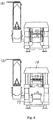
- FIG. 4-A the means for introducing molding sand 6 is carried by the carriage 12, which is driven by the extension and contraction of the second cylinder 14, to the position right above the molding flask 2 and the filling frame 3 that are mounted on the model plate 1a in a superimposed state.
- Fig. 4-B the sand tank 10 is lowered by the contraction of two first cylinders 13 of the means for introducing molding sand 6, whereby the plurality of feet 4 of the shielding means 15 enters the filling frame 3 above the upper model plate 1a.
- the plurality of feet 4 is lifted and lowered so that it matches the position of the model part of the upper model plate 1a. Namely, the plurality of feet 4 is lifted or lowered so that the lower surfaces of the plurality of feet 4 are spaced apart at predetermined distances from the model part of the upper model plate 1a, which model part faces the lower surfaces of the plurality of feet 4.
- the molding space is formed by the upper model plate 1a, the molding flask 2, the filling frame 3, and the plurality of feet 4.
- the predetermined distances between the lower surfaces of the plurality of feet 4 and the model part of the upper model plate 1a, which model part faces the lower surfaces of the plurality of feet 4, are decided in such a way that where the height of the model part is greater, the amount of sand that is compressed so as to mold a mold is made smaller by having the feet 4 lowered and where the height of the model part is smaller, the amount of sand that is compressed is increased with the feet 4 being kept in a lifted position.
- the molding sand in the molding space is squeezed with the plurality of squeezing feet 7 of the squeezing means 8, all the surfaces of the squeezing feet 7 finally recede to nearly the same level as that of the surface of the molding flask 2.
- the molding flask 2 and the filling frame 3 disposed in the squeezing means 8 are lowered via the ceiling frame 18 and placed on a lower model plate 1b, by two hydraulic cylinders 17 of the squeezing means 8 being contracted.
- facing sand is introduced onto the upper model plate 1a.
- the molding sand in the sand tank 10 is being fluidized by the compressed air that is injected from the means for fluidizing molding sand of the means for introducing molding sand 6, the molding sand is introduced into the molding flask 2 and the filling frame 3 that are above the upper model plate 1a by the compressed air being supplied to the upper surface of the molding sand in the sand tank 10.
- the molding sand in the molding flask 2 and the filling frame 3 b is pre-compressed by the sand tank 10 and the plurality of feet 4, etc., being lowered by the first two hydraulic cylinders 13 further contracted.
- the upper model plate 1a, the molding flask 2 and the filling frame 3, etc., into which model plate, flask, and frame the molding sand has been introduced are transferred from the position right below the means for introducing molding sand 6 to the position right below the plurality of squeezing feet 7 of the squeezing means 8.
- the lower model plate 1b, the molding flask 2 and the filling frame 3, etc. are transferred from the position right below the plurality of squeezing feet 7 to the position right below the means for introducing molding sand 6.
- the plurality of squeezing feet 7 are preset by the plurality of squeezing feet 7 being lifted and lowered corresponding to the shape of the model part of the upper model plate 1a. Namely, the lower surfaces of the plurality of squeezing feet 7 are individually adjusted to keep the predetermined distances from the model part of the upper model plate 1a, facing the lower surface of the plurality of squeezing feet 7, by the plurality of squeezing feet 7 being lifted or lowered.
- the predetermined distances between the lower surfaces of the plurality of squeezing feet 7 and the model part of the upper model plate 1a, facing the lower surfaces of the plurality of squeezing feet 7, are determined in such a way that where the height of the model part is greater, the amount of sand that is compressed by the squeezing feet 7 is decreased accordingly and where the height of the model part is smaller, the amount of sand that is compressed is made greater holding the squeezing feet 7 in a lifted position.
- the upper mold and the lower mold are molded in turn.
- the equipment for molding a mold with a molding flask of the present invention comprises:
- the equipment further comprises a squeezing means 108 that has a plurality of squeezing feet 107, the squeezing means being provided adjacent to the means for introducing molding sand 106 and squeezes the molding sand in the molding flask 102 and the filling frame 103, and a turntable 109, as a transfer means, for carrying the model plate 101, the molding flask 102 and filling frame 103 into and out of both the means for introducing molding sand 106 and the squeezing means 108.
- the means for introducing molding sand 106 is provided, within a sand tank 110 that stores the molding sand, with a means for fluidizing molding sand (not shown) that fluidizes the molding sand by injecting compressed air.
- the sand tank 110 is installed on a carriage (not shown) that can move to the left and right.
- the sand tank 110 can be lifted and lowered by means of two cylinders (not shown).
- the sand tank 110 and the carriage, etc. can move into and out of the place right above a filling frame 103, which is explained later.
- the lower part of the sand tank 110 has a shape that forks into two branches and each branch of the folk has an outlet 111 for discharging molding sand at the lowest end. Further, a plurality of feet 104 are provided between these two outlets 111 for discharging molding sand and can be lifted and lowered.
- the squeezing means 108 has, at the middle of a base plate 112 a hydraulic cylinder 113 facing upward, which cylinders lift and lowers the model plate 101, the molding flask 102 and the filling frame 103.
- a hoisting table 114 To the upper end of the piston rod of the hydraulic cylinder 113, is fastened a hoisting table 114 that can place the model plate 101 on it.
- two support pillars 115, 115 in a standing position are placed on the left and right sides of the base plate 112.
- two support pillars 115, 115 is installed on the left and right sides of the base plate 112.
- a ceiling frame 116 is installed at the middle of a base plate 112 .
- the mechanism for blowing compressed air 117 comprises, a pressure tank 118 that, together with the ceiling frame 116, constitutes a pressure vessel; a plurality of ventholes (not shown) provided at the ceiling frame 116 so as to penetrate it and communicate into the inner side of the pressure tank 118; and a valve means (not shown) that can open and close the plurality of the ventholes and that is provided within the pressure tank 118 in such a way that it can be lifted and lowered.
- a plurality of squeezing feet 107 is provided on the lower surface of and at the middle of the ceiling frame 116, which feet can each be lifted and lowered by a plurality of hydraulic cylinders (not shown)
- a pair of roller frames 119 that can extend in the backward and forward directions are suspended at their upper ends and spaced apart at a predetermined distance in the left and right directions.
- the pair of roller frames 119 are rotatably held at their upper ends, and the distance between each frame of the pair of roller frames 119 is widened and closed by the extension and contraction of a cylinder (not shown).
- a plurality of flanged rollers 120 which can move backward and forward the molding flask 102 that is placed on the flanged rollers 120, is disposed at the lower ends of and the inner sides of a pair of roller frames 119.
- the plurality of flanged rollers 120 are supported at the axes of the rollers and positioned in a row in the backward and the forward directions space apart from each other at a predetermined distance.
- hook members 121 on which the filling frame 103 is to be hooked, protrude at the inner sides of and at the upper parts of the pair of the roller frames 119.
- a turntable 109 is disposed at the left support pillar 115, wherein the turntable 109 can turn on the horizontal level at 180 degrees at certain intervals around the center of the turntable.
- the upper model plate 101a for molding the upper mold and the lower model plate 101b for molding the lower mold are loaded at the left side and right side ends of the turntable 109 respectively, so that they can be pushed up.
- the model plate 101 (the upper model plate 101a and the lower model plate 101b) is provided with a vent-plug (not shown) as a means for ventilation.
- FIG. 10-A the means for introducing molding sand 106 is carried right above and close to the molding flask 102 and the filling frame 103 that are mounted on the upper model plate 101a in a superimposed state.
- An empty mold flask 102 is transferred onto the flanged rollers 120 of the pair of roller frames 119 of the squeezing means 108.
- the sand tank 110 is lowered by means of cylinders of the means for introducing molding sand 106, and the plurality of feet 104 of the shielding means 105 is lifted and lowered corresponding to the shape of the model part of the upper model plate 101a, and also a plurality of feet 104 is advanced into the filling frame 103 that is above the upper model plate 101a.
- the plurality of feet 104 is lifted or lowered so that their lower surfaces keep the predetermined distances from the model part of the upper model plate 101a, which part faces the lower surfaces of the plurality of feet 104, thus forming the molding space by the upper model plate 101a, the molding flask 102 and the filling frame 103 and the plurality of feet 104.
- the predetermined distances between the lower surfaces of the plurality of feet 104 and the model part of the upper model plate 101a, which model part faces the lower surfaces of the plurality of feet 104 are determined in such a way that where the height of the model part is greater the amount of sand that is compressed so as to mold a mold is made smaller by having the feet 104 lowered and where the height of the model part is smaller, the amount of sand that is compressed is increased with the relevant feet 104 being kept at a lifted position.
- the molding flask 102 and the filling frame 103 are mounted on a lower model plate 101b of a hoisting table 114 in a superimposed state by the hoisting table 114 being hoisted by the extension of hydraulic cylinder 113.
- the facing sand is introduced onto the upper model plate 101a.
- the molding sand in the sand tank 110 is being fluidized by the compressed air that is injected from the means for fluidizing molding sand of the means for introducing molding sand 106
- the molding sand is introduced into the molding flask 102 and the filling frame 103 that are above the upper model plate 101a by the compressed air being supplied to the upper surface of molding sand in the sand tank 110.
- the filling frame 103 is separated from two hook members 121 by the distance being increased between each frame of the pair of roller frames 119 of the squeezing means 108 and is placed on the molding flask 102.
- the plurality of feet 104 is separated from the filling frame 103 that is above the upper model plate 101a, by the sand tank 110 being lifted by means of the hydraulic cylinders of the means for introducing molding sand 106, and then the plurality of feet 104 is further lifted.
- the lower model plate 101b, the molding flask 102 and the filling frame 103 are lowered by the contraction of the hydraulic cylinder 113 of the squeezing means 108 and then placed on the turntable 109.
- the upper model plate 101a, the molding flask 102 and the filling frame 103, etc., to which model plate, flask, and frame the molding sand is introduced are transferred by the rotation of the turntable 109 from the position right below the means for introducing molding sand 106 to the position right below the plurality of squeezing feet 107 of the squeezing means 108.
- the lower model plate 101b, the molding flask 102 and the filling frame 103, etc. are transferred by the rotation of the turntable 109 from the position right below the plurality of squeezing feet 107 to the position right below the means for introducing molding sand 106.
- the molding sand within the space surrounded by the upper model plate 101a, the molding flask 102 and the filling frame 103, etc. is pre-compressed by the compressed air injected from a mechanism for blowing compressed air 117 of the squeezing means 108.
- the pre-compressed molding sand is squeezed by the upper model plate 101a, etc., being lifted by the hydraulic cylinder 113 of the squeezing means 108 further extended.
- the turntables 9, 109 are used as a transfer means.
- the transfer means is not limited to the turntable of the embodiment. Any means that has a function to move the molding flasks 2, 102 and the filling frames 3, 103, mounted on the model plates 1, 101 in superimposed state, into and out of the means for introducing molding sand 6, 106 and the squeezing means 8, 108, in turn, such as a shuttle means, a means using a roller conveyor, can be used.
Landscapes
- Engineering & Computer Science (AREA)
- Mechanical Engineering (AREA)
- Casting Devices For Molds (AREA)
Applications Claiming Priority (3)
| Application Number | Priority Date | Filing Date | Title |
|---|---|---|---|
| JP2007146833 | 2007-06-01 | ||
| JP2007329574 | 2007-12-21 | ||
| PCT/JP2008/058922 WO2008149651A1 (ja) | 2007-06-01 | 2008-05-15 | 鋳枠付き鋳型の造型設備および鋳枠付き鋳型の造型方法 |
Publications (3)
| Publication Number | Publication Date |
|---|---|
| EP2151290A1 EP2151290A1 (en) | 2010-02-10 |
| EP2151290A4 EP2151290A4 (en) | 2016-11-02 |
| EP2151290B1 true EP2151290B1 (en) | 2017-11-29 |
Family
ID=40093476
Family Applications (1)
| Application Number | Title | Priority Date | Filing Date |
|---|---|---|---|
| EP08752782.6A Active EP2151290B1 (en) | 2007-06-01 | 2008-05-15 | Equipment for molding mold with molding flask, and method for molding mold with molding flask |
Country Status (7)
| Country | Link |
|---|---|
| US (1) | US8186416B2 (pt) |
| EP (1) | EP2151290B1 (pt) |
| JP (1) | JP4830022B2 (pt) |
| CN (1) | CN101687250A (pt) |
| BR (1) | BRPI0811975B1 (pt) |
| ES (1) | ES2655018T3 (pt) |
| WO (1) | WO2008149651A1 (pt) |
Families Citing this family (6)
| Publication number | Priority date | Publication date | Assignee | Title |
|---|---|---|---|---|
| TWI482675B (zh) * | 2009-12-04 | 2015-05-01 | Sintokogio Ltd | Mold modeling device and mold modeling method |
| CN102892531B (zh) * | 2010-05-13 | 2015-09-30 | 新东工业株式会社 | 铸型造型装置以及铸型造型方法 |
| JP5626639B2 (ja) * | 2010-08-09 | 2014-11-19 | 新東工業株式会社 | 鋳型造型方法 |
| RU2472600C1 (ru) * | 2011-05-24 | 2013-01-20 | Закрытое Акционерное Общество "Литаформ" | Способ изготовления литейных форм и устройство для его осуществления |
| CN102672794B (zh) * | 2012-06-06 | 2014-05-28 | 瑞泰科技股份有限公司 | 一种生产熔铸耐火材料的复合砂型成型工艺 |
| JPWO2016103992A1 (ja) * | 2014-12-26 | 2017-10-05 | メタルエンジニアリング株式会社 | 鋳型造型方法およびその装置 |
Family Cites Families (14)
| Publication number | Priority date | Publication date | Assignee | Title |
|---|---|---|---|---|
| JPH0833819B2 (ja) | 1982-09-28 | 1996-03-29 | 富士通株式会社 | プログラム保護装置 |
| JPS5958545U (ja) * | 1982-10-12 | 1984-04-17 | 株式会社栗本鉄工所 | 鋳型造型時の肌砂セツト用枠 |
| DE3713937A1 (de) | 1987-04-25 | 1988-11-03 | Badische Maschf Gmbh | Verfahren zur herstellung von giessformen und formanlage zur durchfuehrung des verfahrens |
| DE8817014U1 (pt) * | 1988-09-07 | 1991-11-21 | Heinrich Wagner Sinto Maschinenfabrik Gmbh, 5928 Bad Laasphe, De | |
| DE3908203A1 (de) * | 1989-03-14 | 1990-09-20 | Badische Maschf Gmbh | Verfahren und vorrichtung zum herstellen von giesserei-formen |
| JP3119334B2 (ja) * | 1993-12-24 | 2000-12-18 | 新東工業株式会社 | 鋳型造型装置 |
| JP3154369B2 (ja) | 1994-02-25 | 2001-04-09 | 新東工業株式会社 | 鋳型造型設備 |
| JP2001138010A (ja) | 1999-11-19 | 2001-05-22 | Sintokogio Ltd | 鋳物砂充填圧縮方法及びその装置並びに鋳物砂投射ノズル |
| KR100837464B1 (ko) * | 2000-02-17 | 2008-06-12 | 신토고교 가부시키가이샤 | 주물사 충전 압축 장치 및 취입 충전 방법 |
| EP1208928B1 (en) * | 2000-04-21 | 2019-10-30 | Sintokogio, Ltd. | Die molding machine and pattern carrier |
| JP4296483B2 (ja) * | 2003-06-19 | 2009-07-15 | 新東工業株式会社 | 鋳型造型方法 |
| JP4096314B2 (ja) | 2004-08-04 | 2008-06-04 | 新東工業株式会社 | 枠付砂鋳型の造型方法 |
| JP2007146833A (ja) | 2005-11-02 | 2007-06-14 | Aisan Ind Co Ltd | 燃料ポンプ |
| JP4561695B2 (ja) | 2006-06-06 | 2010-10-13 | セイコーエプソン株式会社 | 階調値変換回路、印刷装置、及び、階調値変換方法 |
-
2008
- 2008-05-15 BR BRPI0811975A patent/BRPI0811975B1/pt active IP Right Grant
- 2008-05-15 EP EP08752782.6A patent/EP2151290B1/en active Active
- 2008-05-15 ES ES08752782.6T patent/ES2655018T3/es active Active
- 2008-05-15 JP JP2009517767A patent/JP4830022B2/ja active Active
- 2008-05-15 US US12/602,375 patent/US8186416B2/en not_active Expired - Fee Related
- 2008-05-15 CN CN200880018495A patent/CN101687250A/zh active Pending
- 2008-05-15 WO PCT/JP2008/058922 patent/WO2008149651A1/ja active Application Filing
Non-Patent Citations (1)
| Title |
|---|
| None * |
Also Published As
| Publication number | Publication date |
|---|---|
| BRPI0811975A2 (pt) | 2015-05-26 |
| JPWO2008149651A1 (ja) | 2010-08-19 |
| ES2655018T3 (es) | 2018-02-16 |
| US8186416B2 (en) | 2012-05-29 |
| EP2151290A4 (en) | 2016-11-02 |
| WO2008149651A1 (ja) | 2008-12-11 |
| CN101687250A (zh) | 2010-03-31 |
| US20100193991A1 (en) | 2010-08-05 |
| EP2151290A1 (en) | 2010-02-10 |
| BRPI0811975B1 (pt) | 2017-02-14 |
| JP4830022B2 (ja) | 2011-12-07 |
Similar Documents
| Publication | Publication Date | Title |
|---|---|---|
| EP2151290B1 (en) | Equipment for molding mold with molding flask, and method for molding mold with molding flask | |
| JP5626639B2 (ja) | 鋳型造型方法 | |
| CN1318162C (zh) | 形成砂模的方法以及实现该方法的模板造型机 | |
| EP1990111B1 (en) | Sand-introducing device using air, and method and apparatus for producing a mold | |
| US6499531B1 (en) | Machine for producing flaskless moulds | |
| MXPA01012791A (es) | Una maquina de moldeo y un portamodelo utilizado por la misma. | |
| TWI683710B (zh) | 鑄模造型機、砂充填壓縮單元及鑄模造型方法 | |
| KR20010092775A (ko) | 사형의 조형 장치 및 그 방법 | |
| KR100949621B1 (ko) | 주형틀없는 상부 주형 및 하부 주형의 조형장치 | |
| KR20070006844A (ko) | 무틀식 상·하 주형의 조형방법 및 그 장치 | |
| US7150621B2 (en) | Casting installation that is intended, in particular for the production of electrodes and the method used in one such installation | |
| KR102397242B1 (ko) | 개량된 중자금형 설치구조를 갖는 주조용 중자 자동 성형장치 | |
| TWI682818B (zh) | 鑄模造型機 | |
| JP2004237285A (ja) | 鋳型造型方法及びその装置並びに鋳枠係脱装置 | |
| KR100789150B1 (ko) | 주조 주형틀의 자동 이송, 가압 성형장치 | |
| US7891404B2 (en) | Machine for producing flaskless molds | |
| JP4292582B2 (ja) | 鋳型の造型方法 | |
| JP3802358B2 (ja) | 鋳物砂の圧縮方法および鋳物砂の造型方法 | |
| US20190111474A1 (en) | Method for molding | |
| CN103752775B (zh) | 用于制造无砂箱砂型的机器 | |
| KR102397245B1 (ko) | 개량된 중자 배출구조를 갖는 주조용 중자 자동 성형장치 | |
| JP2001138010A (ja) | 鋳物砂充填圧縮方法及びその装置並びに鋳物砂投射ノズル | |
| JP2001129641A (ja) | 鋳型の造型方法及び造型装置 | |
| JPH03148B2 (pt) | ||
| JP2002001491A (ja) | 鋳型の造型方法及び造型装置 |
Legal Events
| Date | Code | Title | Description |
|---|---|---|---|
| PUAI | Public reference made under article 153(3) epc to a published international application that has entered the european phase |
Free format text: ORIGINAL CODE: 0009012 |
|
| 17P | Request for examination filed |
Effective date: 20091124 |
|
| AK | Designated contracting states |
Kind code of ref document: A1 Designated state(s): AT BE BG CH CY CZ DE DK EE ES FI FR GB GR HR HU IE IS IT LI LT LU LV MC MT NL NO PL PT RO SE SI SK TR |
|
| AX | Request for extension of the european patent |
Extension state: AL BA MK RS |
|
| DAX | Request for extension of the european patent (deleted) | ||
| RA4 | Supplementary search report drawn up and despatched (corrected) |
Effective date: 20160930 |
|
| RIC1 | Information provided on ipc code assigned before grant |
Ipc: B22C 15/02 20060101AFI20160926BHEP Ipc: B22C 15/24 20060101ALI20160926BHEP Ipc: B22C 15/28 20060101ALI20160926BHEP |
|
| GRAP | Despatch of communication of intention to grant a patent |
Free format text: ORIGINAL CODE: EPIDOSNIGR1 |
|
| STAA | Information on the status of an ep patent application or granted ep patent |
Free format text: STATUS: GRANT OF PATENT IS INTENDED |
|
| INTG | Intention to grant announced |
Effective date: 20170725 |
|
| GRAS | Grant fee paid |
Free format text: ORIGINAL CODE: EPIDOSNIGR3 |
|
| GRAA | (expected) grant |
Free format text: ORIGINAL CODE: 0009210 |
|
| STAA | Information on the status of an ep patent application or granted ep patent |
Free format text: STATUS: THE PATENT HAS BEEN GRANTED |
|
| AK | Designated contracting states |
Kind code of ref document: B1 Designated state(s): AT BE BG CH CY CZ DE DK EE ES FI FR GB GR HR HU IE IS IT LI LT LU LV MC MT NL NO PL PT RO SE SI SK TR |
|
| REG | Reference to a national code |
Ref country code: GB Ref legal event code: FG4D |
|
| REG | Reference to a national code |
Ref country code: CH Ref legal event code: EP |
|
| REG | Reference to a national code |
Ref country code: AT Ref legal event code: REF Ref document number: 949919 Country of ref document: AT Kind code of ref document: T Effective date: 20171215 |
|
| REG | Reference to a national code |
Ref country code: IE Ref legal event code: FG4D |
|
| REG | Reference to a national code |
Ref country code: DE Ref legal event code: R096 Ref document number: 602008053167 Country of ref document: DE |
|
| REG | Reference to a national code |
Ref country code: ES Ref legal event code: FG2A Ref document number: 2655018 Country of ref document: ES Kind code of ref document: T3 Effective date: 20180216 |
|
| REG | Reference to a national code |
Ref country code: NL Ref legal event code: MP Effective date: 20171129 |
|
| REG | Reference to a national code |
Ref country code: LT Ref legal event code: MG4D |
|
| REG | Reference to a national code |
Ref country code: AT Ref legal event code: MK05 Ref document number: 949919 Country of ref document: AT Kind code of ref document: T Effective date: 20171129 |
|
| PG25 | Lapsed in a contracting state [announced via postgrant information from national office to epo] |
Ref country code: LT Free format text: LAPSE BECAUSE OF FAILURE TO SUBMIT A TRANSLATION OF THE DESCRIPTION OR TO PAY THE FEE WITHIN THE PRESCRIBED TIME-LIMIT Effective date: 20171129 Ref country code: FI Free format text: LAPSE BECAUSE OF FAILURE TO SUBMIT A TRANSLATION OF THE DESCRIPTION OR TO PAY THE FEE WITHIN THE PRESCRIBED TIME-LIMIT Effective date: 20171129 Ref country code: SE Free format text: LAPSE BECAUSE OF FAILURE TO SUBMIT A TRANSLATION OF THE DESCRIPTION OR TO PAY THE FEE WITHIN THE PRESCRIBED TIME-LIMIT Effective date: 20171129 Ref country code: NO Free format text: LAPSE BECAUSE OF FAILURE TO SUBMIT A TRANSLATION OF THE DESCRIPTION OR TO PAY THE FEE WITHIN THE PRESCRIBED TIME-LIMIT Effective date: 20180228 |
|
| REG | Reference to a national code |
Ref country code: FR Ref legal event code: PLFP Year of fee payment: 11 |
|
| PG25 | Lapsed in a contracting state [announced via postgrant information from national office to epo] |
Ref country code: HR Free format text: LAPSE BECAUSE OF FAILURE TO SUBMIT A TRANSLATION OF THE DESCRIPTION OR TO PAY THE FEE WITHIN THE PRESCRIBED TIME-LIMIT Effective date: 20171129 Ref country code: AT Free format text: LAPSE BECAUSE OF FAILURE TO SUBMIT A TRANSLATION OF THE DESCRIPTION OR TO PAY THE FEE WITHIN THE PRESCRIBED TIME-LIMIT Effective date: 20171129 Ref country code: GR Free format text: LAPSE BECAUSE OF FAILURE TO SUBMIT A TRANSLATION OF THE DESCRIPTION OR TO PAY THE FEE WITHIN THE PRESCRIBED TIME-LIMIT Effective date: 20180301 Ref country code: BG Free format text: LAPSE BECAUSE OF FAILURE TO SUBMIT A TRANSLATION OF THE DESCRIPTION OR TO PAY THE FEE WITHIN THE PRESCRIBED TIME-LIMIT Effective date: 20180228 Ref country code: LV Free format text: LAPSE BECAUSE OF FAILURE TO SUBMIT A TRANSLATION OF THE DESCRIPTION OR TO PAY THE FEE WITHIN THE PRESCRIBED TIME-LIMIT Effective date: 20171129 |
|
| PG25 | Lapsed in a contracting state [announced via postgrant information from national office to epo] |
Ref country code: NL Free format text: LAPSE BECAUSE OF FAILURE TO SUBMIT A TRANSLATION OF THE DESCRIPTION OR TO PAY THE FEE WITHIN THE PRESCRIBED TIME-LIMIT Effective date: 20171129 |
|
| PG25 | Lapsed in a contracting state [announced via postgrant information from national office to epo] |
Ref country code: CZ Free format text: LAPSE BECAUSE OF FAILURE TO SUBMIT A TRANSLATION OF THE DESCRIPTION OR TO PAY THE FEE WITHIN THE PRESCRIBED TIME-LIMIT Effective date: 20171129 Ref country code: DK Free format text: LAPSE BECAUSE OF FAILURE TO SUBMIT A TRANSLATION OF THE DESCRIPTION OR TO PAY THE FEE WITHIN THE PRESCRIBED TIME-LIMIT Effective date: 20171129 Ref country code: EE Free format text: LAPSE BECAUSE OF FAILURE TO SUBMIT A TRANSLATION OF THE DESCRIPTION OR TO PAY THE FEE WITHIN THE PRESCRIBED TIME-LIMIT Effective date: 20171129 Ref country code: CY Free format text: LAPSE BECAUSE OF FAILURE TO SUBMIT A TRANSLATION OF THE DESCRIPTION OR TO PAY THE FEE WITHIN THE PRESCRIBED TIME-LIMIT Effective date: 20171129 Ref country code: SK Free format text: LAPSE BECAUSE OF FAILURE TO SUBMIT A TRANSLATION OF THE DESCRIPTION OR TO PAY THE FEE WITHIN THE PRESCRIBED TIME-LIMIT Effective date: 20171129 |
|
| REG | Reference to a national code |
Ref country code: DE Ref legal event code: R097 Ref document number: 602008053167 Country of ref document: DE |
|
| PG25 | Lapsed in a contracting state [announced via postgrant information from national office to epo] |
Ref country code: RO Free format text: LAPSE BECAUSE OF FAILURE TO SUBMIT A TRANSLATION OF THE DESCRIPTION OR TO PAY THE FEE WITHIN THE PRESCRIBED TIME-LIMIT Effective date: 20171129 Ref country code: IT Free format text: LAPSE BECAUSE OF FAILURE TO SUBMIT A TRANSLATION OF THE DESCRIPTION OR TO PAY THE FEE WITHIN THE PRESCRIBED TIME-LIMIT Effective date: 20171129 Ref country code: PL Free format text: LAPSE BECAUSE OF FAILURE TO SUBMIT A TRANSLATION OF THE DESCRIPTION OR TO PAY THE FEE WITHIN THE PRESCRIBED TIME-LIMIT Effective date: 20171129 |
|
| PLBE | No opposition filed within time limit |
Free format text: ORIGINAL CODE: 0009261 |
|
| STAA | Information on the status of an ep patent application or granted ep patent |
Free format text: STATUS: NO OPPOSITION FILED WITHIN TIME LIMIT |
|
| 26N | No opposition filed |
Effective date: 20180830 |
|
| PG25 | Lapsed in a contracting state [announced via postgrant information from national office to epo] |
Ref country code: SI Free format text: LAPSE BECAUSE OF FAILURE TO SUBMIT A TRANSLATION OF THE DESCRIPTION OR TO PAY THE FEE WITHIN THE PRESCRIBED TIME-LIMIT Effective date: 20171129 |
|
| REG | Reference to a national code |
Ref country code: CH Ref legal event code: PL |
|
| GBPC | Gb: european patent ceased through non-payment of renewal fee |
Effective date: 20180515 |
|
| REG | Reference to a national code |
Ref country code: BE Ref legal event code: MM Effective date: 20180531 |
|
| PG25 | Lapsed in a contracting state [announced via postgrant information from national office to epo] |
Ref country code: MC Free format text: LAPSE BECAUSE OF FAILURE TO SUBMIT A TRANSLATION OF THE DESCRIPTION OR TO PAY THE FEE WITHIN THE PRESCRIBED TIME-LIMIT Effective date: 20171129 |
|
| REG | Reference to a national code |
Ref country code: IE Ref legal event code: MM4A |
|
| PG25 | Lapsed in a contracting state [announced via postgrant information from national office to epo] |
Ref country code: CH Free format text: LAPSE BECAUSE OF NON-PAYMENT OF DUE FEES Effective date: 20180531 Ref country code: LI Free format text: LAPSE BECAUSE OF NON-PAYMENT OF DUE FEES Effective date: 20180531 |
|
| PG25 | Lapsed in a contracting state [announced via postgrant information from national office to epo] |
Ref country code: LU Free format text: LAPSE BECAUSE OF NON-PAYMENT OF DUE FEES Effective date: 20180515 |
|
| PG25 | Lapsed in a contracting state [announced via postgrant information from national office to epo] |
Ref country code: GB Free format text: LAPSE BECAUSE OF NON-PAYMENT OF DUE FEES Effective date: 20180515 Ref country code: IE Free format text: LAPSE BECAUSE OF NON-PAYMENT OF DUE FEES Effective date: 20180515 |
|
| PG25 | Lapsed in a contracting state [announced via postgrant information from national office to epo] |
Ref country code: BE Free format text: LAPSE BECAUSE OF NON-PAYMENT OF DUE FEES Effective date: 20180531 |
|
| PG25 | Lapsed in a contracting state [announced via postgrant information from national office to epo] |
Ref country code: MT Free format text: LAPSE BECAUSE OF NON-PAYMENT OF DUE FEES Effective date: 20180515 |
|
| PG25 | Lapsed in a contracting state [announced via postgrant information from national office to epo] |
Ref country code: TR Free format text: LAPSE BECAUSE OF FAILURE TO SUBMIT A TRANSLATION OF THE DESCRIPTION OR TO PAY THE FEE WITHIN THE PRESCRIBED TIME-LIMIT Effective date: 20171129 |
|
| PG25 | Lapsed in a contracting state [announced via postgrant information from national office to epo] |
Ref country code: PT Free format text: LAPSE BECAUSE OF FAILURE TO SUBMIT A TRANSLATION OF THE DESCRIPTION OR TO PAY THE FEE WITHIN THE PRESCRIBED TIME-LIMIT Effective date: 20171129 Ref country code: HU Free format text: LAPSE BECAUSE OF FAILURE TO SUBMIT A TRANSLATION OF THE DESCRIPTION OR TO PAY THE FEE WITHIN THE PRESCRIBED TIME-LIMIT; INVALID AB INITIO Effective date: 20080515 |
|
| PG25 | Lapsed in a contracting state [announced via postgrant information from national office to epo] |
Ref country code: IS Free format text: LAPSE BECAUSE OF FAILURE TO SUBMIT A TRANSLATION OF THE DESCRIPTION OR TO PAY THE FEE WITHIN THE PRESCRIBED TIME-LIMIT Effective date: 20180329 |
|
| PGFP | Annual fee paid to national office [announced via postgrant information from national office to epo] |
Ref country code: FR Payment date: 20230525 Year of fee payment: 16 Ref country code: DE Payment date: 20230519 Year of fee payment: 16 |
|
| PGFP | Annual fee paid to national office [announced via postgrant information from national office to epo] |
Ref country code: ES Payment date: 20230724 Year of fee payment: 16 |