EP2149727B1 - Hydrokinetisches Kupplungsgerät, das eine Verschlusskupplung mit perfektionierten progressiven Mitteln umfasst - Google Patents
Hydrokinetisches Kupplungsgerät, das eine Verschlusskupplung mit perfektionierten progressiven Mitteln umfasst Download PDFInfo
- Publication number
- EP2149727B1 EP2149727B1 EP09165711A EP09165711A EP2149727B1 EP 2149727 B1 EP2149727 B1 EP 2149727B1 EP 09165711 A EP09165711 A EP 09165711A EP 09165711 A EP09165711 A EP 09165711A EP 2149727 B1 EP2149727 B1 EP 2149727B1
- Authority
- EP
- European Patent Office
- Prior art keywords
- friction
- piston
- axially
- bead
- progressivity
- Prior art date
- Legal status (The legal status is an assumption and is not a legal conclusion. Google has not performed a legal analysis and makes no representation as to the accuracy of the status listed.)
- Ceased
Links
Images


Classifications
-
- F—MECHANICAL ENGINEERING; LIGHTING; HEATING; WEAPONS; BLASTING
- F16—ENGINEERING ELEMENTS AND UNITS; GENERAL MEASURES FOR PRODUCING AND MAINTAINING EFFECTIVE FUNCTIONING OF MACHINES OR INSTALLATIONS; THERMAL INSULATION IN GENERAL
- F16H—GEARING
- F16H45/00—Combinations of fluid gearings for conveying rotary motion with couplings or clutches
- F16H45/02—Combinations of fluid gearings for conveying rotary motion with couplings or clutches with mechanical clutches for bridging a fluid gearing of the hydrokinetic type
- F16H2045/021—Combinations of fluid gearings for conveying rotary motion with couplings or clutches with mechanical clutches for bridging a fluid gearing of the hydrokinetic type three chamber system, i.e. comprising a separated, closed chamber specially adapted for actuating a lock-up clutch
-
- F—MECHANICAL ENGINEERING; LIGHTING; HEATING; WEAPONS; BLASTING
- F16—ENGINEERING ELEMENTS AND UNITS; GENERAL MEASURES FOR PRODUCING AND MAINTAINING EFFECTIVE FUNCTIONING OF MACHINES OR INSTALLATIONS; THERMAL INSULATION IN GENERAL
- F16H—GEARING
- F16H45/00—Combinations of fluid gearings for conveying rotary motion with couplings or clutches
- F16H45/02—Combinations of fluid gearings for conveying rotary motion with couplings or clutches with mechanical clutches for bridging a fluid gearing of the hydrokinetic type
- F16H2045/0215—Details of oil circulation
-
- F—MECHANICAL ENGINEERING; LIGHTING; HEATING; WEAPONS; BLASTING
- F16—ENGINEERING ELEMENTS AND UNITS; GENERAL MEASURES FOR PRODUCING AND MAINTAINING EFFECTIVE FUNCTIONING OF MACHINES OR INSTALLATIONS; THERMAL INSULATION IN GENERAL
- F16H—GEARING
- F16H45/00—Combinations of fluid gearings for conveying rotary motion with couplings or clutches
- F16H45/02—Combinations of fluid gearings for conveying rotary motion with couplings or clutches with mechanical clutches for bridging a fluid gearing of the hydrokinetic type
- F16H2045/0273—Combinations of fluid gearings for conveying rotary motion with couplings or clutches with mechanical clutches for bridging a fluid gearing of the hydrokinetic type characterised by the type of the friction surface of the lock-up clutch
- F16H2045/0278—Combinations of fluid gearings for conveying rotary motion with couplings or clutches with mechanical clutches for bridging a fluid gearing of the hydrokinetic type characterised by the type of the friction surface of the lock-up clutch comprising only two co-acting friction surfaces
-
- F—MECHANICAL ENGINEERING; LIGHTING; HEATING; WEAPONS; BLASTING
- F16—ENGINEERING ELEMENTS AND UNITS; GENERAL MEASURES FOR PRODUCING AND MAINTAINING EFFECTIVE FUNCTIONING OF MACHINES OR INSTALLATIONS; THERMAL INSULATION IN GENERAL
- F16H—GEARING
- F16H45/00—Combinations of fluid gearings for conveying rotary motion with couplings or clutches
- F16H45/02—Combinations of fluid gearings for conveying rotary motion with couplings or clutches with mechanical clutches for bridging a fluid gearing of the hydrokinetic type
- F16H2045/0273—Combinations of fluid gearings for conveying rotary motion with couplings or clutches with mechanical clutches for bridging a fluid gearing of the hydrokinetic type characterised by the type of the friction surface of the lock-up clutch
- F16H2045/0284—Multiple disk type lock-up clutch
-
- F—MECHANICAL ENGINEERING; LIGHTING; HEATING; WEAPONS; BLASTING
- F16—ENGINEERING ELEMENTS AND UNITS; GENERAL MEASURES FOR PRODUCING AND MAINTAINING EFFECTIVE FUNCTIONING OF MACHINES OR INSTALLATIONS; THERMAL INSULATION IN GENERAL
- F16H—GEARING
- F16H45/00—Combinations of fluid gearings for conveying rotary motion with couplings or clutches
- F16H45/02—Combinations of fluid gearings for conveying rotary motion with couplings or clutches with mechanical clutches for bridging a fluid gearing of the hydrokinetic type
- F16H2045/0273—Combinations of fluid gearings for conveying rotary motion with couplings or clutches with mechanical clutches for bridging a fluid gearing of the hydrokinetic type characterised by the type of the friction surface of the lock-up clutch
- F16H2045/0294—Single disk type lock-up clutch, i.e. using a single disc engaged between friction members
Definitions
- the present invention relates to a hydrokinetic coupling apparatus comprising a locking clutch provided with improved progressivity means.
- Such a device is known to DE 198 08 299 A1 .
- the housing having a first rear shell carrying the impeller wheel constitutes the inlet of the apparatus connected to the driving shaft and the outlet is constituted at least by a turbine wheel - hub unit housed inside the housing and connected to the driven shaft.
- the turbine wheel and the impeller wheel form a converter in which, conventionally, the turbine wheel is driven by the impeller wheel through the circulation of a fluid contained in the housing, usually oil.
- the driving shaft is the engine output shaft of the vehicle and the driven shaft is connected to gearshift means.
- Such a hydrokinetic coupling apparatus is generally equipped with a locking clutch which is still called a "lock-up".
- the locking clutch is intended to allow, after starting the vehicle, the control of the sliding between the turbine and impeller wheels by controlling the driving of the driving shaft, which is connected to the housing, by the shaft driven, which is connected to the turbine wheel, so as to connect directly to one another to improve the efficiency.
- driving of the driven shaft by the driven shaft is effected by the locking clutch which is able to directly rotate the housing and the turbine wheel so as to minimize energy absorption in torque transmission between driving and driven shafts.
- the locking clutch comprises for this purpose a piston which is implanted between the turbine-hub wheel assembly and a substantially radial wall carried by a second shell of the casing which, being rotatably connected to the first shell of the casing, also constitutes the input element of the device.
- the piston is mounted axially movable, relative to said wall, between at least one operating position (bridging) and a rest position.
- the axial displacement of the piston between these extreme positions is controlled by the variable application of a given pressure on either side of the piston to selectively bind the piston in rotation to the wall.
- the drive control of the shafts via a locking clutch is carried out in a manner known per se by clamping at least a first friction surface that includes a first element against a second associated friction surface carried by a second element.
- the second element is for example constituted by the second front shell of the housing whose wall forms the second friction surface with which cooperates, in the operating position (bridging), the first friction surface of the first element.
- the first element- is for example constituted by the piston of the locking clutch carrying a friction lining when the application is of "single-sided” type or by a friction disc carrying two friction linings which is interposed between the piston and the wall of the second shell before the casing, when the application is of the "two-sided" type.
- the second element When the application is of the "multi-faceted" type, the second element then consists of at least one flange which, bearing the second friction surface, is rotatably connected to the second shell of the casing.
- the second element is able to cooperate selectively, when the piston axially applies a clamping force intended to establish the coupling of the driving and driven shafts, with the first associated friction surface which is carried by a friction disc.
- control means establish a sufficient hydraulic pressure to cause the movement of the piston and perform the bridging.
- the object of the invention is in particular to solve the aforementioned drawbacks and to propose a locking clutch capable of guaranteeing comfort and pleasure during gear changes as well as a contact pressure distribution at the friction surfaces which is optimal. and uniform and still capable of compensating geometrical defects and deformations of the elements due in particular to the variable operating conditions.
- the invention proposes a hydrokinetic coupling device of the type described above, characterized in that the locking clutch of the apparatus comprises progressivity means which, elastically deformable in at least the axial direction, consist of by at least a first bead and a second bead, generally coaxial with the first bead, said first and second cords being respectively interposed axially between at least one proximal bearing surface carried by the first element comprising the first friction surface intended to cooperate by friction with the second associated friction surface and a distal bearing surface carried by an adjacent element to which said first element is rotatably connected by means of connecting means, and in that it comprises aperture means capable of to allow, during the bridging by the piston, a variation of pressure in a space delimited axially by proximal and distal support faces and radially the first and second cords.
- the locking clutch of the apparatus comprises progressivity means which, elastically deformable in at least the axial direction, consist of by at least a first bead and a second bead, generally coaxial
- the progressivity means according to the invention are able to deform in operation, especially to suppress jolts, so as to ensure comfort to the user during gear changes.
- the progressivity means according to the invention are also able to compensate for the geometrical defects and the deformations of the parts, in particular the cone-setting phenomenon, so as to guarantee an optimal and uniform distribution of the contact pressure between said elements. first and second friction surfaces.
- the progressivity means according to the invention make it possible to increase the comfort perceived by the driver by allowing a faster rise in the pressure controlling the bridging by the piston, which reduces the time required to make a gear change. speed without causing jolts.
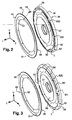
- FIG. 1 a hydrokinetic coupling apparatus 10, in particular for a motor vehicle, comprising according to a first application a locking clutch 12, also called “lock-up” in English terminology, which is of "single-sided” type.
- the locking clutch 12 is generally so designated due to the fact that it has only one friction lining and this in comparison with the second and third applications described later, in connection with the figures 19 and following, for which the locking clutch 12 comprises respectively two and more than two friction linings, from which it follows the associated designations of type "bifaces" and type "multifaceted".
- the locking clutch 12 of the "single-sided" type for hydrokinetic coupling apparatus 10 is therefore only a possible and non-limiting example of application of the invention.
- the hydrokinetic coupling apparatus 10 comprises a main axis X-X of rotation around which are arranged the different parts.
- the "forward” and “backward” orientations correspond respectively to the left and the right of the figure 1 along the axis of rotation XX which, extending longitudinally, determines the "axial” orientation as opposed to the "radial” orientation which is orthogonal to it and which extends vertically along the trihedron (L, V, T).
- outer or outer and inner or inner are used to define the relative position of one element relative to another according to the radial orientation corresponding to the vertical direction and, with reference to the main axis of rotation XX, an element near the axis XX is thus termed internal as opposed to an external element -which is located radially at the periphery.
- the hydrokinetic coupling apparatus 10 comprises a sealed casing 14 formed respectively of a first rear shell 14B and a second front shell 14A, which are preferably assembled by welding.
- the rear shells 14B and 14A of the casing 14 delimit an internal volume 16 of the apparatus 10 inside which are mainly arranged a torque converter 18, the locking clutch 12 and a damping device 20.
- the torque converter 18 comprises a rear impeller wheel 22, a front turbine wheel 24 and, preferably, a central reaction wheel 26.
- the impeller wheel 22 comprises vanes 22a which are carried by the first rear shell shell 14B, which is rotationally integral with the second front shell 14A of the casing 14, for example by welding.
- the second front shell 14A is here able to be connected in rotation to a drive shaft (not shown), in particular by means of coupling means comprising on the one hand nut connecting means 15 and, on the other hand, a centering member 17.
- the connecting means 15 are for example reported by welding on the radial front face of the second front shell 14A and are intended to receive screws to ensure the attachment of the apparatus 10 with a flange or flexible wheel (not shown) of the engine .
- the second front shell 14A being integral in rotation with the first rear shell 14B, thus ensures the connection between the drive shaft and the impeller wheel 22 of the converter.
- the turbine wheel 24 comprises vanes 24a which axially face the vanes 22a of the impeller wheel 22 in order to ensure the rotational drive of the turbine wheel 24 by the impeller wheel 22 thanks to the circulation between the vanes 22a, 24a of a fluid contained in the casing 14, in general of the oil.
- the turbine wheel 24 is rotatably connected to a driven shaft A2 (shown in dashed line) which is coaxial with the main axis XX of the apparatus 10, said rotational connection being a no-play connection made via at least one intermediate piece advantageously capable of being rotatably connected to the driven shaft A2 and to the turbine wheel 24 respectively.
- said intermediate piece is constituted by a turbine hub 28 which provides the rotational connection of the turbine wheel 24 with the driven shaft A2.
- the driving shaft is constituted by the crankshaft of the internal combustion engine of the vehicle, while the driven shaft A2 is constituted by the input shaft of the vehicle transmission. conventionally connected to gearshift means.
- the turbine hub 28 generally has, in axial section, an "L" shape having a radially oriented portion and an axially oriented portion.
- the radially inner end of the shell of the turbine wheel 24 is fixed by riveting, alternatively by welding, on the end of the radially oriented part of the hub 28.
- the radially oriented portion of the hub 28 has at its free end on the one hand a first rear countersink for centering the end of the shell of the turbine wheel 24 and, on the other hand, a second front counterbore so that the heads of rivets are axially included in the depth of the countersink and do not extend axially protruding forwardly.
- the rotational drive between the turbine hub 28 and the driven shaft A2 is conventionally formed by cooperation of shapes between grooves and axial grooves formed respectively on one and / or the other.
- the driven shaft A2 has at its axial end a chamfer intended in particular to facilitate the mounting of radially interposed sealing means between the turbine hub 28 and the shaft A2, axially in front of the meshing portion between grooves and grooves.
- the hydrokinetic coupling apparatus 10 further comprises the damping or damping device 20 which is interposed axially between the torque converter 18 and the locking clutch 12.
- damper 20 is likely to vary depending on the applications, including its arrangement as illustrated, for example, in the case of the first application with a locking clutch 12 single-sided, a comparison between the figures 1 and 7 .
- such a damper 20 mainly comprises an input member 30 and an output member 32 between which are interposed elastic members 34 with circumferential action.
- the input element 30 and the output element 32 of the damper 20 are constituted by parts respectively designated as a washer (s) and sail, or vice versa.
- the damper 20 comprises an input element 30 constituted by a driving and guiding piece integral with the piston 36, here by riveting, and an output element 32 constituted by another piece provided with tabs which is secured here by welding, a top portion of the shell of the turbine wheel 24.
- the elastic members 34 with circumferential action are interposed between the input 30 and output 32 of the damper elements and are for example formed by coil springs, preclinear or not.
- the input element 30 comprises, on the one hand, a first radially inner portion in the form of a flat ring which is riveted on the piston 36 in order to fix and connect it in rotation and, on the other hand, a second portion generally shaped half-torus which extends for the most part in the space delimited radially on the outside by the piston 36.
- the second portion of the input element 30 has, in axial section, a C-profile defining a concavity open axially forward towards the second front shell 14A of the casing and forming a circumferential groove in which are received the elastic members 34 with circumferential action.
- the second portion of the input element 30 has openings to allow the axial passage of the tabs forming the output member 32 connected to the shell of the turbine wheel 24.
- the elastic members 34 are circumferentially guided and retained axially by the input member 30.
- the elastic members 34 are interposed between the tabs of the output member 32 and other sets of pairs of drive lugs which, constituting a double support, are formed in known manner by cutting and / or stamping in the second portion of the input element 30.
- the tabs forming the output element 32 comprise, at the level of the zones in contact with the elastic members 34, centering and holding studs which penetrate inside the end turns of each elastic member 34.
- the locking clutch 12 of the single-sided type ( figure 1 ) mainly comprises a piston 36 which is axially movable and which is intended to link, in a disengageable manner, the second front shell 14A of the casing 14 to the driven shaft A2.
- the operation of the hydrokinetic coupling apparatus 10 comprises a first phase of operation, called “converter phase” and a second phase, called “coupling phase”.
- the torque of the drive shaft is transmitted by the casing 14 to the impeller wheel 22 which drives, by circulation of oil between the blades 22a and 24a, the turbine wheel 24.
- the damper 20 substantially does not interfere with the damping of the vibrations or torsional oscillations due mainly to the acyclisms of the motor (not shown) comprising the apparatus 10.
- vibrations or torsional oscillations are filtered in the oil by the converter 18 since the transmission of the engine torque is achieved by means of the kinetic energy of the oil in the converter 18.
- the piston 36 is displaced axially from the rear towards the front under the action of a difference in the pressure of the oil applying on either side of the piston 36 to clamp axially against each other friction surfaces S1, S2.
- the locking clutch 12 is generally controlled after the starting of the vehicle and after the hydraulic coupling of the driving and driven shafts A2, to avoid the loss of efficiency induced in particular by the slip phenomena occurring between the impeller wheels 22 and turbine 24.
- the piston 36 is mounted axially movable relative to the axially oriented portion of the turbine hub 28, which portion extends axially in front of the other portion of radial orientation secured to the end of the turbine wheel 24.
- the piston 36 comprises at its inner periphery a first L-shaped portion, similar to that of the hub 28, whose axially oriented portion constitutes a shell 37 which extends axially forward and cooperates with a means of sealing 38, such as a segment or a seal.
- the sealing means 38 is interposed between the internal sliding surface of the piston 36 formed by the ferrule 37 and the surface facing the hub 28, so as to ensure the seal between a first chamber, known as the control 40 and a second chamber, said turbine chamber 42.
- the sealing means 38 is here borne by the hub 28, alternatively by the piston 36, and housed in an annular groove of the hub 28 which preferably comprises a terminal chamfer in order to facilitate the fitting by fitting of the sealing means. 38 in the throat.
- the piston 36 extends generally radially outwards by the other radial portion of the L of the first portion, and then by a second intermediate portion, here in the form of a V lying and which substantially matches the shape of the second front shell 14A of the housing and ends with a third portion still L-shaped having a radial portion and an axial portion which, extending rearwardly, forms a stiffening skirt 39.
- the piston 36 is able to be selectively controlled to proceed with the bridging, that is to say the displacement of the piston 36 towards its operating position in which the piston axially tightens at least a first friction surface S1 that comprises a first element against a second associated friction surface S2 that comprises a second element.
- said first element is constituted respectively by a friction lining 44 having the first friction surface S1 and a friction disk 46 on one front of the faces which the friction lining 44 is attached to fixation, in particular by gluing, and whose rear face, axially opposite, constitutes a proximal bearing face 48.
- the friction disc 46 is removed and the first element consists of the only friction lining 44 comprising a first face forming the first friction surface S1 and a second opposite face forming the proximal bearing face 48.
- the friction disk 46 comprises connecting means capable of cooperating with complementary connection means for integrally linking in rotation, without circumferential clearance, the first element formed by the friction lining 44 and the friction disk 46 to an adjacent element formed by the piston 36, said adjacent element having a distal support face 50.
- the friction disk 46 comprises an inner portion 52 in the form of a ring which extends circumferentially in a continuous manner, radially below an external portion on which the friction lining 44 is attached to attachment.
- the inner portion 52 and the outer portion of the friction disc 46 are not coplanar, said portions being radially connected to each other by an oblique intermediate portion forming a fold.
- the inner annular portion 52 is adapted to be fixed to the piston 36 by riveting by means of rivets 54 which are preferably distributed circumferentially in a regular manner.
- the rivets 54 provide the connection in rotation between the first element 44, 46 and the adjacent element 36.
- the rivets 54 also ensure the rotational connection of the input element 30 of the damper 20 with the piston 36.
- the outer portion of the friction disc 46 carrying the friction lining 44 is, due to the oblique intermediate portion, axially offset forwardly with respect to the inner portion 52 so as to creating a given axial clearance between the proximal face 48 and the distal face 50, respectively carried by the friction disk 46 and by the piston 36.
- said second element is constituted by the second front shell 14A of the casing, a rear wall 56 of which has an outer peripheral portion which, extending radially and axially vis-à-vis the first friction surface S1, forms the second surface complementary friction S2 against which said first friction surface S1 is selectively clamped by the piston 36 according to whether the locking clutch 12 is in the operating position (bridging) or rest.
- the friction lining 44 is provided with grooves whose profile can vary and which notably make it possible to improve the cooling in the vicinity of the second friction surface S2 carried by the rear wall 56 of the casing 14 and to work in sliding control.
- the cooling of the second friction surface S2 formed by a portion of the rear wall 56 is effected by conduction through the second casing front shell 14A whose front wall is generally in contact with the ambient air surrounding the engine. .
- the driven shaft A2 has an axial bore opening at the forward free end of this shaft. This bore communicates with the control chamber 40, which is delimited axially by the wall 56 of the housing and the piston 36, and which is supplied with oil under pressure by a hydraulic circuit connected to said bore.
- the coupling of the shafts A2 is first established by the impeller wheel 22 and the turbine wheel 24 of the converter 18 during the converter phase, then by the locking clutch 12 which is activated during the coupling phase so that the driving shaft, which is connected to the impeller wheel 22 by the housing 14, is secured to the driven shaft A2 by the turbine hub 28 connecting it to the turbine wheel 24.
- the control of the piston 36 of the locking clutch 12 is obtained by varying the pressure on either side of the piston 36, that is to say between the control chamber 40 and the turbine chamber 42, the piston 36 being moved axially forward to establish the bridging or locking (operating position) of the piston 36 and the wall 56 of the housing 14 and, conversely, rearward for disassembly or unlocking (rest position).
- the locking clutch 12 of the apparatus 10 comprises progressivity means which, elastically deformable in at least the axial direction, consist of at least a first bead 58 forming a first progressive means and a second cord 60 forming a second progressive means, generally coaxial with the first cord 58.
- first and second beads 58, 60 are respectively interposed axially between the proximal bearing face 48 carried by the friction disk 46 forming the first element which comprises the first friction surface S1 and a distal support face 50 carried by the piston 36 forming the adjacent element to which said first element is connected in rotation through connecting means formed by the rivets 54.
- the progressivity means 58, 60 make it possible to solve the aforementioned drawbacks by proposing a locking clutch 12 in particular capable of reducing or even eliminating jolts and of guaranteeing a distribution of contact pressure at the level of the contact surfaces. friction S1, S2 which is optimal and uniform.
- the locking clutch 12 is advantageously capable of compensating geometrical defects and deformations of the elements such as the piston 36 or the casing 14 due in particular to the variable operating conditions.
- Such progressivity means of a locking clutch 12 are able to compensate for deformations of the order of 0.3 to 0.5 mm which contributes very favorably to an improvement in the operation of the locking clutch 12 and his control or command in general.
- the progressivity means 58, 60 comprise opening means 62 able to allow, during the clamping by the piston 36, a variation of pressure in a space E which axially delimits the faces of proximal support 48 and distal 50 and radially the first and second beads 58, 60.
- the term “annular” when the space E is designated as “annular” space, the term “annular” must not be interpreted restrictively as a circular or toroidal signifier, the shape of the space E being in particular a function of the shape of the cords that surround it and delimit it radially.
- the annular space E therefore extends circumferentially around the main axis XX along a loop path whose geometric characteristics are determined by those of the cords so that the course of the course can be for example circular or sinuous.
- the annular space E is therefore not filled with air but with oil that is able to circulate through said opening means 62 so as to allow a pressure variation, especially during the bridging, it is that is, when the piston 36 of the locking clutch 12 is moved from its rest position to its operating position.
- the pressure applied to the first friction surface S1 carried by the piston 36 is likely to reach maximum values of the order of 5 to 7 bars depending on the application.
- the apparatus 10 further comprises sealing means 64 able to establish, for the one-way locking clutch 12, the control pressure required to axially move the piston 36 towards its operating position, called the bridging position, in which the friction surfaces S1 and S2 cooperate to ensure the coupling of the driving and driven shafts A2.
- the sealing means 64 are constituted by the inner portion 52 of the friction disc 46 attached to the piston 36 by the rivets 54 forming the connecting means.
- the rotational connection between the first element, formed by the friction lining 44 and the friction disc 46, and the adjacent element is made by welding, for example by a circular weld bead circumferentially continuous, so to ensure tightness between the chambers 40 and 42 during the bridging.
- sealing means are constituted by a sealing member, such as a seal or any other suitable means.
- such a sealing member must allow to isolate the chambers 40 and 42 when the piston 36 is in the operating position.
- the sealing member is preferably interposed radially axially between the proximal bearing face 48 of the first element, for example the friction disc 46 carrying the friction lining 44, and the distal bearing surface 50 of the adjacent element, for example the piston 36.
- Such a sealing member is then arranged radially inside both progressivity means formed for example by the first and second cords 58, 60 which it is distinct, that connecting means in rotation by meshing of the first element 44. , 46 with the adjacent element 36.
- the sealing member is a lip seal (s) whose body is received in a complementary groove that includes the adjacent element formed for example by the piston 36 so that the lip or lips cooperate with the face rear radial located axially vis-à-vis belonging to the first element, the friction disc 46 or the friction lining 44.
- the sealing means are constituted at least by the second bead 60 which is interposed axially between the proximal bearing face 48 carried by the first element 44, 46 which has the first friction surface S1 and the distal face support 50 carried by the adjacent element 36 to the first element 44, 46.
- the second cord 60 of the progressivity means is then circumferentially continuous to ensure the function of étanehéotti means 64, alternatively at least one of the cords 58, 60 is continuous to form a sealing means 64.
- the second bead 60 is made of the same elastomer material as the elastically deformable progressivity means formed by at least the first bead 58.
- the sealing means are formed by the progressivity means, different elastomeric materials are used to produce the bead that exclusively provides a progressivity function on the one hand, and the bead providing at least the sealing function.
- the first and second cords 58, 60 forming the progressivity means are respectively made in the form of circumferentially discontinuous bead and each consist of four curvilinear portions, preferably arcuate.
- Each bead 58, 60 comprises, between two consecutive portions, a radial passage orifice 62 forming said opening means, respectively passage holes 62E in the first bead 58 radially outwardly and through openings 62I in the second bead 60 radially on the inside.
- the arcuate portions forming respectively the first cord 58 and the second cord 60 are for example four in number, and the number of radial through holes 62E, 62I formed in each of the cords 58, 60.
- the arcuate portions forming respectively the first cord 58 and the second cord 60 are of equal length between them and from one cord to another.
- the arcuate portions respectively forming the first bead 58 and the second bead 60 are distributed circumferentially in a regular manner around the periphery of the piston 36 forming the adjacent element and the portions of the first bead 58 are angularly offset relative to the portions. the second cord 60 so that the radial passage holes of one and the other are not aligned in the radial direction.
- the angular offset between the arcuate portions of each of the cords 58, 60 is determined in such a way that a radial orifice 62E, 62I of one opens radially in the middle of one of the arcuate portions of circle of the other.
- the second bead 60 is coaxial with the first bead 58 so that the second bead 60 is arranged radially inside said first bead 58.
- the elastically elastic progressivity means 58, 60 are made of an elastomer material, such as a thixotropic silicone, having stable characteristics when it is immersed in the oil contained in the internal volume 16 of the casing 14 of the hydrokinetic coupling apparatus 10.
- At least the progressivity means 58, 60 are made of a material chosen from fluoro-silicones which are particularly suitable for such applications in the oil.
- the elastomeric material of the progressivity means 58, 60 is able to be adhered directly by polymerization with one and / or the other of the proximal support faces 48 of the first element and distal 50 of the adjacent element.
- the polymerization of the elastomeric material is obtained by heating, for a predetermined period, for example between 2 and 12 minutes, at a temperature greater than or equal to a given polymerization temperature, for example of the order of 150 ° C.
- heating generally reduces the polymerization time of the elastomeric material.
- the polymerization of the elastomeric material is carried out cold, that is to say at room temperature.
- the choice of the method for carrying out the polymerization is a function of the type of elastomer material.
- the elastomeric material forming the progressivity means is adhered to the proximal bearing face 48 of the first element and / or the distal bearing face 50 of the adjacent element 36 by gluing through a adhesive capable of binding the elastomeric material integrally to the respective materials of the first element formed in particular by the friction disc 46 or directly by the friction lining 44 and the adjacent element formed by the piston 36 or by the wall 56 of the second shell before 14A of the housing.
- the elastically deformable progressivity means formed by the cords 58 and 60 according to the first embodiment are integral with each of the proximal support faces 48 of the first element and distal 50 of the adjacent element.
- the elastically deformable progressivity means formed by the beads 58 and 60 are respectively integral with only one of the proximal 48 and distal 50 support faces, so that the opening means 62 for allowing pressure variation in the annular space E are constituted, not by radial passage orifices, but by the axial clearance thus created between the progressivity means 58, 60 and one of the proximal 48 and distal 50 support surfaces with which the one and / or the other means of progressivity is not bound together.
- the opening means 62 intended to allow the variation of pressure in the annular space E consist of at least one hole axially passing through the piston 36 so as to establish a communication between the annular space E in which said minus one circulation hole opens and the inner volume 16 of the housing 14 filled with oil.
- the opening means 62 intended to allow the pressure variation in the annular space E consist of at least one hole axially traversing the friction disc 46 and / or the friction lining 44 so as to establish a communication between the annular space E in which the at least one circulation hole opens and the interior volume 16 of the casing 14 filled with oil.
- the opening means 62 intended to allow the pressure variation in the annular space E consist of at least one hole axially traversing the piston 36 and at least one hole axially traversing the friction disc 46 and / or the friction lining 44 so as to establish a communication between the annular space E in which the at least one circulation hole opens and the interior volume 16 of the casing 14 filled with oil.
- the opening means 62 intended to allow the pressure variation in the annular space E are then constituted by at least one radial orifice passage made selectively in all or part of the cords 58, 60 forming the means of progressivity.
- the opening means 62 are able to establish in the annular space E included radially between the first bead 58 and the second bead 60, a circulation of clean oil to allow effective cooling , in particular a cooling of the proximal bearing face 48 of the first element formed by the friction disk 46 to which the heat of the first friction surface S1 of the friction lining 44 which it carries is transmitted by conduction.
- the cords 58 and 60 forming the progressivity means have, in axial section, a substantially constant section so that the proximal 48 and distal 50 support faces. radially extend generally parallel to each other with an axial spacing "e", between the first element 46 having the proximal bearing surface and the adjacent element 36 having the distal bearing surface, substantially constant.
- the cords 58 and 60 have, in axial section, an increasing section in the radial direction in an orientation going from the inside to the outside so that the axial spacing "e", comprised between the first element comprising the proximal bearing surface and the adjacent element having the distal bearing face increases in the radial direction to incline the friction lining 44 by a determined angle.
- the first element comprising the first friction surface S1 and the proximal bearing surface 48 is inclined at a given angle with respect to a radial plane orthogonal to the axis XX and the distal support face 50 of the adjacent element 36 extends radially orthogonal to the axis XX.
- the first bead 58 has an elastic stiffness different from the elastic stiffness of the second bead 60.
- axial abutment means are interposed between the proximal 48 and distal 50 support faces so as to limit the elastic deformation of the progressivity means 58, 60 in the axial direction.
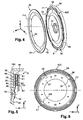
- the figure 3 represents a second embodiment in which the first bead 58 is formed in the form of pads which are advantageously distributed circumferentially in a regular manner on the periphery of the piston 36.
- the pads 58 forming the first progressiveness cord have a generally circular section.
- the second bead 60 is in the form of an open bead having two semi-circular portions which are interrupted at each end by a radial orifice 62I.
- the sealing means 64 are obtained by rotationally connecting the inner annular portion 52 of the friction disk 46 with the piston 36 by means of rivets 54.
- the figure 4 represents a third embodiment in which the first bead 58 is made in the form of an interrupted bead having four curvilinear portions which each extend circumferentially in a corrugated pattern, for example of the sinusoidal type.
- the second bead 60 is closed, ie circumferentially continuous, so that the opening means on the annular space E consist of the only through holes 62E formed between the successive portions of the first bead 58.
- FIGS. 5 and 6 represent a second embodiment in which the adjacent element is constituted, either by the piston 36, but by the second front casing shell 14A whose rear radial face, ie the wall 56, constitutes the distal face 50.
- the first element is formed by the friction disc 46 which is secured to a friction lining 44 having the first friction surface S1.
- the first friction surface S1 is here facing rearward and is intended to cooperate with a second friction surface S2 axially vis-à-vis which is formed by the radial front face of the piston 36 constituting the second element.
- the locking clutch 12 of the apparatus 10 comprises sealing means able to establish, between the chambers 40 and 42, a control pressure capable of causing the displacement of the piston 36, axially towards the front, until reaching the operating position (bridging) in which the first and second friction surfaces S1, S2 frictionally cooperate to couple the driving and driven shafts A2.
- the sealing means are constituted by the connecting means formed by the inner radial portion 52 of the friction disc 46 having the proximal bearing face 48, or the first element, which cooperates with the wall 56 of the second front shell 14A having the distal support face 48, the adjacent element, the portion 52 of the friction disc 46 is fixed to the wall 56 by means of rivets 54 ', preferably of extruded type, for connecting them in rotation.
- connection in rotation between the first element, formed by the friction disc 46 carrying the friction lining 44, and the adjacent element formed by the second shell 14A is formed by meshing or welding.
- the elastically deformable progressivity means comprise at least a third cord 59 which, advantageously forming an additional means of progressivity, is generally coaxial with the first and second beads 58 and 60.
- the third bead 59 is arranged radially inside the first bead 58 and outside the second bead 60 so that the third bead 59 is arranged radially between the first bead 58 and the second bead 60.
- the third cord 59 is made in the form of a closed bead, that is to say circumferentially continuous, which cooperates with each of the proximal and distal support faces 48, 50 forms an additional means of sealing by compared to extruded rivets 54 '.
- such a third bead 59 is therefore capable of forming the required sealing means when the connecting means are not such as to provide this function, typically when the connection in rotation between the first element and the adjacent element is achieved. by meshing.
- the sealing means are then also likely to be constituted by a separate sealing member, for example in the form of a seal interposed axially between the proximal and distal support surfaces 48, 50 and arranged radially between the unsealed connection means and the progressivity means formed by the cords 58, 59 and 60, and this in order to dissociate the progressivity and sealing functions.
- the third bead 59 delimits radially a first annular space E1 with the first bead 58 and a second annular space E2 with the second bead 60, said spaces E1, E2 being delimited axially by the proximal 48 and distal 50 support faces.
- the proximal 48 and distal 50 bearing surfaces respectively cooperate with at least the third progressivity cord 59, in particular if the cord 59 is also a sealing means.
- all progressivity cords 58, 59 and 60 are integral with the proximal bearing face 48 of the first element and the distal face 50 of the adjacent element.
- progressivity cords 58, 59, 60 are not able to transmit a torque between the first element and the adjacent element, the transmission of torque is ensured by the connecting means in rotation (by riveting, welding or meshing) intervening between said elements.
- the opening means 62 intended to allow the variation of pressure in each of the annular spaces E1, E2 consist of radial through-holes 62E and 62I made selectively in the progressivity cords 58 and 60 respectively.
- the opening means 62E, 62I are able to establish in each of the annular spaces E1, E2 a circulation of clean oil to allow cooling, in particular a cooling of the proximal bearing face 48 of the friction disc 46 forming the first element and having the first friction surface S1.
- the third bead 59 is continuous while the first and second cords 58, 60 are interrupted by the circumferentially discontinuous orifices 62E, 62I, which are in the form of four arc portions, similarly to those of the figure 2 .
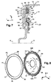
- FIGS. 7 and 8 represent a fourth embodiment of the progressivity means according to the invention which will be described in particular by comparison with the previous examples.
- the damper 20 of the apparatus 10 which is similar to that of the figure 1 , is implanted on a smaller diameter and partly enveloped by the intermediate portion of the piston 36.
- the adjacent element is constituted by the piston 36 of the locking clutch 12 whose front radial face forms the distal bearing face 50.
- the first element is formed by the friction disc 46 carrying the friction lining 44 which has the first friction surface S1 intended to cooperate with the second friction surface S2 carried by the rear radial face 56 of the second front shell 14A of casing .
- the elastically deformable progressivity means comprise a third bead 59 forming an additional means of progressivity, said bead 59 being generally coaxial with first and second cords 58, 60.
- the third bead 59 delimits radially a first annular space E1 with the first bead 58 and a second annular space E2 with the second bead 60, the said annular spaces E1, E2 being further delimited axially by the proximal and distal support faces 48, 50 .
- the rotational connection between the first element, formed by the friction disk 46 carrying the friction lining 44, and the adjacent element formed by the piston 36, is made by meshing, ie cooperation of tooth-like shapes between complementary male and female elements.
- the locking clutch 12 comprises sealing means constituted by at least one of the cords, such as the third cord 59 which, arranged radially between the first and second cords 58, 60, is circumferentially continuous or closed.
- the opening means 62 intended to allow the variation of pressure in each of the annular spaces E1, E2 consist of a pair of through-holes 62E or 62I made respectively in the first bead 58 and in the second bead 60, preferably diametrically opposed for each pair and angularly offset at 90 ° from one pair to the other.
- the oil circulation established in each of the annular spaces E1 and E2 makes it possible to obtain optimum cooling.
- At least one of the cords 58, 59, 60 has an elastic stiffness different from the elastic stiffness of at least one of the other cords, in particular the first cord 58 and / or the third cord 59.
- the friction disk 46 comprises, like the inner part 52 previously, an outer part 66 which extends radially beyond the friction lining 44 and in which are arranged housings 68 intended to cooperate with complementary connecting means for meshing by cooperation of forms.
- the housings 68 are distributed circumferentially in a regular manner so that the portion 66 of the friction disc 46 generally has a slot-shaped profile.
- the piston 36 comprises at its outer radial periphery said complementary connecting means intended to cooperate with the connecting means formed by the housings 68.
- the complementary means are constituted by tabs 70 which, extending axially towards the front, are adapted to integrally bond in rotation, without circumferential clearance, the friction disc 46 (or first element) to the piston 36 (or adjacent element) having the distal support face 50.
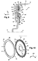
- FIGS. Figures 7 and 8 represent a fifth embodiment of the invention which will be described hereinafter by comparison, particularly with the fourth embodiment illustrated in FIGS. Figures 7 and 8 .
- the first element is formed by the friction disc 46 carrying the friction lining 44 which comprises the first friction surface S1 intended to cooperate with the second friction surface S2 formed by the rear radial face 56 of the second front casing shell 14A while the adjacent element is constituted by the piston 36 of the locking clutch 12 whose front radial face forms the distal bearing face 50.
- the elastically deformable progressivity means comprise three concentric cords, respectively first and second cords 58, 60 arranged radially outside and inside a third cord 59.
- the third bead 59 delimits radially a first annular space E1 with the first bead 58 and a second annular space E2 with the second bead 60, the said annular spaces E1, E2 being further delimited axially by the proximal and distal support faces 48, 50 .
- the first and second beads 58 and 60 are closed, that is to say circumferentially continuous, and are integral with the proximal and distal bearing surfaces 48 and 50 so that they respectively constitute sealing means capable of permitting establishing a control pressure between the chambers 40 and 42 to effect bridging by axially moving the piston 36 forward to its operating position in which the first and second friction surfaces cooperate.
- the opening means associated with progressivity cords 58, 59 and 60 respectively consist, on the one hand, of through-holes 62 made in the third cord 59 and, on the other hand, of through holes 72 axially the piston 36 and opening into the annular spaces E1, E2.
- the first annular space E1 and the second annular space E2 are placed in communication with one another via the radial passage orifices 62 of the third cord 59 and with the outside, ie the oil included in the internal volume 16, via the axial holes 72.
- the third bead 59 has three through-holes 62 circumferentially distributed regularly at 120 ° and the piston 36 also has axial holes 72 which are three in number.
- orifices 62 and / or holes 72 forming the opening means is given by way of non-limiting example and may vary depending on the applications.
- the axial holes 72 are here arranged radially in the piston 36 so as to open axially at the radial passage openings 62 of the third cord 59 and therefore in both annular spaces E1 and E2.
- sealing means 64 are arranged radially inside the latter so that the chambers 40 and 42 are not in communication with each other and that the piston 36 can be moved to its operating position during bridging.
- the progressive means consist of first, second and third cords 58, 59 and 60 which are all closed or circumferentially continuous and integral proximal and distal support faces 48 and 50 so as to form sealing means.
- opening means are provided and made in the form of axial holes through the piston 36 associated with each annular space. E1, E2.
- the opening means comprise respectively a first series of axial holes 72E which open between the cords 58 and 59 in the annular space E1 and a second series of axial holes 721 which open between the cords 59 and 60.
- the first series of holes 72E forming the opening means of the first annular space E1 and the second series of holes 721 forming the opening means of the second annular space E2 are angularly offset relative to each other.
- the opening means on the one hand preserves the integrity of the cords 58, 59 and 60 when, for the bridging, a pressure of up to 5 bars, for example, is applied to the piston 36 and, on the other hand, a circulation of oil is established in each of the annular spaces E1 and E2 which causes a cooling of the proximal bearing face 48 adjacent the friction disc 46 and thus of the friction lining 44 carried by the opposite face.
- At least one 58 of the cords 58, 59, 60 has an elastic stiffness different from the elastic stiffness of at least one of the other cords, in particular the second cord 58 and / or the third cord 59.
- the figure 13 represents a seventh embodiment in which the progressivity means are constituted, as for the first embodiment, by two concentric cords respectively a first bead 58 and a second bead 60.
- the locking clutch 12 comprises stop means 74 for axially limiting the elastic deformation of the cords 58, 60 forming the progressivity means according to the invention.
- the abutment means 74 are integrally attached to the proximal bearing face 48 of the friction disc 46 and are arranged radially in the annular space E delimited by the cords 58 and 60.
- the abutment means 74 consist for example of pads of elastomeric material with a stiffness suitable for limiting the elastic deformation of the cords, the pads 74 are for example fixed by gluing or any other appropriate means on the face 48.
- the rigidity of the abutment means 74 is determined to guarantee a minimum axial separation between the proximal bearing face 48 and the distal bearing face 50 of the piston 36 so as to limit the compression of the cords 58, 60 below. 'a value to preserve them while achieving sufficient progressivity.
- the first bead 58 has a circumferentially discontinuous shape determining opening means 62, such as a radial passage orifice, between two consecutive shapes and the second bead 60 is closed so as to constitute the sealing means allowing establishing the control pressure to axially move the piston 36 of the locking clutch 12.
- the cords 58, 60 have, in axial section, a substantially constant section so that the proximal 48 and distal 50 bearing faces extend radially globally. parallel to each other with an axial spacing "e" between the friction disc 46 and the piston 36, substantially constant.
- the figure 14 represents an eighth embodiment in which, compared to the figure 13 , the axial abutment means 74 are formed by a stamping which, formed in the piston 36, extends axially in the annular space E delimited by the first bead 58 and the second bead 60.
- the axial abutment means 74 are formed by a stamping formed in the friction disc 46 and which preferably extends axially in the annular space E delimited by the first bead 58 and the second bead 60.
- the axial abutment means 74 are arranged radially outside and inside the first bead 58 and the second bead 60 so that the annular space E is free of any obstacle for the circulation of the oil participating in cooling adjacent faces 48 and 50.
- FIGS. 15A and 15B represent a ninth embodiment of progressiveness means illustrated respectively in rest (disassembly) and operating (bridging) positions of the locking clutch 12.
- the sealing means 64 are constituted by the second circumferentially continuous cord 60 which, integral with the proximal bearing face 48 and the distal support face 50, is arranged radially inside the cords 58 and 59
- the second cord 60 which provides a dual function of progressivity on the one hand and sealing, on the other hand, the other cords 58 and 59 are integral with each of the proximal 48 and distal 50 support faces.
- the opening means 62 intended to allow the variation of pressure in each of the annular spaces E1, E2 consist of at least one radial passage orifice 62 made selectively in each of the cords 58 and 59.
- the cords 58, 59 and 60 have, in axial section, an increasing section in the radial direction and in an orientation from the inside to the outside so that the axial gap "e", between the first member formed by the friction disc 46 having the proximal bearing face 48 and the adjacent member formed by the piston 36 having the radially increasing distal bearing face 50, the friction lining 44 carried by the friction disc 46 be inclined.
- the first friction surface S1 of the friction lining 44 and the proximal bearing surface 48 carried by the friction disk 46 are respectively inclined by an angle ( ⁇ ) determined with respect to a radial plane orthogonal to the axis XX the distal bearing surface 50 of the piston 36 extending radially orthogonal to the axis XX.
- the friction lining 44 is inclined so that, during the bridging, the radially inner portion of the lining 44 forming the first friction surface S1 between the first contact with the second friction surface S2 formed by the wall 56 of the second casing front shell 14A, that is to say before the radially outer portion which, due to the inclination, extends axially backwards.
- FIGS 16 and 17 represent a tenth example embodiment in which the beads 58, 59 and 60 are interposed axially between the distal bearing face 50 of the piston 36 forming the adjacent element and the proximal bearing face 48 of the first element which is formed directly by a friction lining 44 provided at its inner radial periphery with rotational connection means, such as lugs 71.
- the tabs 71 are advantageously made in one piece, made of material, with the friction lining 44 and the friction disc 46 removed.
- the tabs 71 extend circumferentially in a regular manner and are capable of cooperating with the notches 69 that comprises the radial front face of the piston 36 to directly produce (without play) the connection in rotation between the friction lining 44 and the piston 36.
- the first element is constituted as before by a friction disc 46 carrying the friction lining 44 and comprises tabs 71 made in one piece, integrally formed, with its radially inner portion 52.
- the opening means 62 of the annular spaces E1 and E2 are constituted by radial through-holes 62 in the first and third beads 58, 59 and the sealing means 64 are formed by the second bead 60.
- the diameter of the friction lining (s) 44 is optimal as long as the meshing-in-rotation connection means are arranged radially inside the friction lining 44.
- the figure 18 illustrates an alternative embodiment in which the means for connection in rotation between the piston 36 and the friction disc 46 are made, not by riveting or meshing, but by welding.
- the welding is carried out in the form of a circumferentially continuous weld bead 76 which rotates the end of the inner radial portion 52 of the friction disk 46 to the distal bearing face 50 of the piston 36.
- the sealing means 64 are then constituted by the weld bead 76 and none of the cords 58, 59 and 60 provide a dual function of progressivity and sealing means such as the second cord 60 for the tenth example of realization illustrated in Figures 16 and 17 preceding.
- the sealing means 64 are here constituted by the connecting means 76 intended to link in rotation the first element 46 comprising the proximal bearing face 48 and the adjacent element 36 comprising the distal support face 50.
- a second application of the invention will be described hereinafter to a "bifaces" locking clutch 12 in comparison with the modes and embodiments described previously for the first application and shown in FIGS. Figures 1 to 18 .
- Such a lock clutch 12 bifaces is represented at the figure 19 , the Figures 19 and 20 illustrating a third embodiment of the progressivity means.
- the turbine hub 28 generally has, in axial section, a shape similar to that of the figure 1 , that is to say in "L”, but comprises respectively a portion of radial orientation and a portion of axial orientation which extends rearwardly.
- the radially inner end of the shell of the turbine wheel 24 is here fixed by rivets 55, alternatively by welding, on the end of the radially oriented part of the hub 28.
- the end of the radially oriented portion of the hub 28 comprises at least counterbore so as to integrate the rivets 55 in the axial thickness and to ensure a radial positioning of the end of the shell of the turbine wheel 24.
- the damper 20 mainly comprises an input element 30 and an output element 32 between which are interposed elastic members 34 with circumferential action.
- the output member 32 of the damper 20 is formed by a radially oriented web which is rotatably connected at its inner periphery to the shell of the turbine wheel 24 and to the turbine hub 28 via rivets 55.
- the output element 32 of the damper 20 has at its outer radial periphery windows in which are mounted the elastic members 34 with circumferential action.
- the input element 30 of the damper 20 is constituted by two guide washers, respectively a front guide ring 30A and a rear guide ring 30B which, integral with each other, are connected in rotation without circumferential play.
- connection of the guide washers 30A and 30B is in particular made by crimping the free end of the outer portion of the front guide ring 30A which extends axially rearwardly, with the outer portion of the guide ring rear 30B which extends radially vis-à-vis.
- Each of the guide washers 30A and 30B comprises stampings so as to form bearing zones for the circumferentially acting elastic members 34.
- the front guide ring 30A includes connecting means, such as drive lugs 78, for rotating the entry of the damper 20 with the locking clutch 12.
- the locking clutch 12 comprises a piston 36 which is axially movable and which is intended to disengageably connect the second front shell 14A of the casing 14 to the driven shaft A2.
- the piston 36 is mounted axially movable with respect to the axially oriented portion of the centralizer 17 integral with the front shell 14A of the casing, the portion of the centralizer 17 extending axially rearwardly in the direction of the turbine hub 28.
- abutment means 80 are capable of being interposed axially between the rear axial end of the centralizer 17 and the turbine hub 28.
- the piston 36 comprises at its inner periphery a first L-shaped portion, similar in this case to that of the hub 28, whose axially oriented portion constitutes a ferrule 37 extending axially towards the rear and cooperates with a sealing means 38, such as a segment or a seal.
- the sealing means 38 is interposed between the internal sliding surface of the piston 36 formed by the ferrule 37 and the external surface facing the centralizer 17, so as to ensure the seal between a first chamber, said chamber 40 and a second chamber, said turbine chamber 42.
- the sealing means 38 is housed in an annular groove formed in the centralizer 17, the centralizer 17 having at the rear a chamfer intended to facilitate their mounting by interlocking and having at the front of the holes 79 intended to put in communication the control chamber 42 with a central bore of the driven shaft A2 through which the oil flows.
- the piston 36 comprises successively in the radial direction and from the inside to the outside, the first internal L-shaped portion which has just been described, a second generally rectilinear intermediate portion which extends parallel to the portion of the second front shell 14A of the casing located vis-à-vis and ends with a third outer portion having a fourth friction surface S4.
- the piston 36 is rotatably connected to the wall 56 formed by the rear radial face of the first front shell 14A of the casing via connecting means 82.
- the connecting means 82 are formed by groups of tongues, distributed circumferentially in a regular manner, each group comprising one or more tongues, one end of which is fixed to the piston 36 and the other end of which is fixed to the first front shell. 14A of the housing.
- the fastening means of the tabs 82 are constituted by rivets, in particular extruded rivets 84 for connection in rotation with the wall 56 of the first front shell 14A of the casing.
- the biface type locking clutch 12 has a first front friction lining 44A and a second rear friction lining 44B which are respectively loosely linked in rotation with a front friction disc 46A and a rear friction disc 46B.
- the friction linings 44A, 44B are secured by bonding the friction discs 46A and 46B associated, alternatively by riveting.
- the locking clutch 12 comprises progressive means which, elastically deformable in at least the axial direction, consist of at least a first bead 58 and a second bead 60, generally coaxial with the first bead 58.
- the progressivity means comprise at least a third cord 59 forming an additional means of progressiveness, generally coaxial with the first and second beads 58, 60.
- the cords 58, 59, 60 forming the progressivity means are respectively interposed axially between at least one proximal bearing face 48 and a distal bearing face 50.
- the third bead 59 defines radially a first annular space E1 with the first bead 58 and a second annular space E2 with the second bead 60, said annular spaces E1 and E2 being delimited axially by the proximal 48 and distal 50 support faces.
- the proximal bearing face 48 is carried by a first element formed by the front friction disc 46A, more precisely by the rear radial face of this disc 46A, the axially opposite front radial face bearing the first friction lining 44A comprising the first friction surface S1.
- the distal bearing surface 50 is carried by an adjacent element formed by the other rear friction disc 46B, more precisely by the front radial face of this disc 46B, the axially opposite rear radial face bearing the second friction lining 44B comprising a third rear friction surface S3.
- the friction discs 46A and 46B are removed and the first element comprising the proximal bearing face 48 and the adjacent element comprising the distal support face 50 are constituted directly by each other.
- friction linings 44A and 44B, the bearing faces 48, 50 being formed by the faces of the linings axially opposite to the friction faces S1, S3.
- the first friction surface S1 that comprises the first front friction lining 44A carried by the front friction disc 46A forming the first element is intended to cooperate with a second friction surface S2 which, axially vis-à-vis, is worn by the rear radial face or wall 56 of the second casing front shell 14A forming a second element.
- the third friction surface S3 that comprises the second rear friction lining 44B carried by the rear friction disk 46B forming the adjacent element is intended to cooperate with the associated fourth friction surface S4 which, axially vis-à-vis, is formed by the radially outer portion of the front radial face of the piston 36.
- said first element and adjacent element formed here respectively by a friction disk 46A, 46B carrying a friction lining 44A, 44B, are provided with connecting means able to bind said components in rotation, directly or with the interposition of a damper 20, to a part rotatably connected to the turbine wheel 24.
- the hydrokinetic coupling apparatus 10 comprising a damper 20 and said piece is constituted by the input member of the damper 20, more precisely here by the front guide washer 30A comprising the driving tabs 78.
- the friction discs 46A, 46B each comprise, at their outer radial periphery, connection means 86, such as notches represented on the figure 20 which are complementary to the drive lugs 78.
- the notches 86 are formed in an outer portion of the disk 46A, 46B which extends radially beyond the inner portion carrying the friction lining 44A, 44B associated, said outer and inner portions of each disk being connected to each other at the favor of an oblique fold so as to shift axially.
- the portions comprising the notches 86 are contiguous and substantially coplanar while the internal portions having the bearing faces 48 and 50 are spaced apart by a given axial spacing so as to allow the implementation of the progressivity means 58, 59 and 60.
- the front friction disk 46A forming the first element is thus rotatably connected to the rear friction disk 46B forming the adjacent element 46B via the meshing linkage means constituted by their respective notches 86 and the driving lugs 78 of the front guide washer 30A.
- the locking clutch 12 also comprises opening means 62 associated with the progressivity means and intended to allow, during the bridging by the piston 36, a pressure variation in the annular spaces E1 and E2 delimited by a part axially the proximal faces 48 and distal support 50 and, secondly, radially said beads 58, 59 and 60.
- the locking clutch 12 comprises sealing means 64 able to establish a control pressure to axially move the piston 36 towards its operating position, called bridging position, in which the friction surfaces S1 and S2 on the one hand and the friction surfaces S3 and S4, on the other hand, respectively cooperate together to couple the driving and driven shafts A2.
- the sealing means 64 are constituted at least by one of the cords 58, 59, 60, preferably here by the third cord 59 arranged radially between the first and second beads 58, 60.
- the third cord 59 is circumferentially continuous, that is to say closed, and cooperates with each of the proximal and distal support faces 48, 50 to ensure the function sealing.
- the first bead 58 is made in the form of four circular arc portions distributed circumferentially in a regular manner and interrupted by four radial passage holes 62E.
- the second cord 60 is made in a similar shape in a circular arc, the second cord 60 having three arc portions interrupted by three radial passage holes 621.
- the opening means 62 consist of at least one hole passing axially through the adjacent element and / or through at least one hole axially passing through the first element, that is to say axially through the gasket. friction 44B and the friction disc 46B and / or through the friction lining 44A and the friction disc 46A so as to establish a communication between each of the associated annular spaces E1 and E2 in which the at least one hole opens and the interior volume 16 of the housing 14 filled with oil.
- the progressivity means 58, 59, 60 are made of an elastomer material, such as a thixotropic silicone, having stable characteristics when it is immersed in the oil contained in the casing 14 of the apparatus 10.
- the opening means 62E, 621 are able to establish in the associated annular spaces E1 and E2, a circulation of clean oil to allow effective cooling of both the proximal bearing face 48 of the friction disc 46A carrying the friction lining 44A having the first friction surface S1, that of the distal bearing surface 50 of the friction disc 46B yet the other friction lining 44B having the third friction surface S3.
- the cords 58, 59 and 60 have, in axial section, a substantially constant section so that the proximal and distal bearing faces 48, 50 extend radially generally parallel to each other with an axial spacing "e" substantially constant .
- the cords 58, 59, 60 have, in axial section, in the radial direction an increasing section such that the axial spacing "e" increases or decreases in an orientation from the inside to the outside so that the friction linings 44A and 44B are inclined with respect to a radial reference plane orthogonal to the main axis XX.
- the beads 58, 59 and 60 have substantially all identical elastic stiffness.
- At least one of the cords 58, 59, 60 has an elastic stiffness different from the elastic stiffness of at least one of the other cords 58, 59, 60.
- the locking clutch 12 of the apparatus comprises axial abutment means capable of limiting the elastic deformation of the progressivity means, such as the abutment means 74 shown in FIGS. Figures 13 and 14 and previously described.
- the hydrokinetic coupling apparatus 10 comprises a sealed housing 14 which, filled with a fluid such as oil, is formed of two generally shell-shaped elements, respectively a first rear shell 14B and a second front shell 14A .
- the shells of the housing 14 delimit an internal volume 16 of the apparatus 10 inside which are mainly arranged a torque converter 18, the locking clutch 12 and a damping or damping device 20.
- the torque converter 18 is similar to that described for the first and second applications and mainly comprises a rear impeller wheel 22, a front turbine wheel 24 and a central reaction wheel 26.
- the impeller wheel 22 comprises blades 22a which are carried by the first rear shell 14B, which is rotatably connected to the other front shell 14A of the casing 14 and the turbine wheel 24 also comprises vanes 24a which face axially to the vanes 22a of the impeller wheel 22.
- the rear shell 14B is able to be connected in rotation to a driving shaft and the turbine wheel 24 adapted to be rotatably connected to a driven shaft A2, coaxial with the main axis X-X of the apparatus 10.
- the driving shaft is constituted by the crankshaft of the internal combustion engine of the vehicle, while the driven shaft A2 is constituted by the input shaft of the vehicle transmission. conventionally connected to gearshift means.
- the connecting means 15 and 17 associated with the second front shell 14A for its connection in rotation to the driving shaft have not been shown, the driven shaft A2 is surrounded by another controlled shaft which , concentric, is connected in rotation, for example by meshing, with the reaction wheel 26.
- the driven shaft A2 is connected to the turbine wheel 24 via at least one piece formed by a turbine hub 28 to which the free end of the shell of the turbine wheel 24 is frictionally bonded. as a variant by riveting.
- the apparatus 10 advantageously comprising a damper 20, the turbine hub 28 is connected to the driven shaft A2 via the damper 20 which comprises an input element 30 and an output element 32.
- the input element 30 of the damper 20 is constituted by guide washers, respectively a front guide ring 30A. and a rear guide washer 30B which is rotatably linked without play to the turbine hub 28 and to the turbine wheel 24, preferably by meshing, alternatively by welding or riveting.
- the guide washers 30A, 30B are secured to rotate from one another by their outer peripheral edges, for example by means of rivets 88.
- the output element 32 of the damper 20 is constituted by at least one web 32.
- the web 32 is linked in play-free rotation to an output hub 90, for example by meshing, the output hub 90 being linked in rotation by meshing with the driven shaft A2.
- the web 32, forming the output element of the damper 20 can be made in one piece with the output hub 90.
- the torque transmitted by the turbine wheel 24 is directly transmitted to the guide washers 30A, 30B forming the input element of the damper 20, then to the web 32 forming the output element of the damper 20, by the intermediate of elastic members 34 with circumferential action, and this after angular displacement of the guide washers 30A, 30B relative to the web 32.
- the damper 20 comprises abutment means (not shown) capable of angularly limiting the circumferential clearance between the guide washers 30A, 30B and the web 32, the web 32 being arranged axially between the guide washers 30A, 30B .
- the elastic members 34 with circumferential action are interposed circumferentially between the guide washers 30A, 30B and the web 32, the web 32 having windows 92 in which the resilient members 34 are received.
- the guide washers 30A, 30B also each comprise a central portion provided with windows 94 arranged axially in line with the windows 92 of the web 32.
- the elastic members 34 abut respectively on the radial edges of the windows 94 of the guide washers 30A, 30B and on the radial edges of the windows 92 of the web 32.
- the elastic members 34 are held axially by the circumferential orientation edges of the windows 94 guide washers 30A, 30B.
- the damper 20 comprises elastic members 34 with circumferential action which are connected by means of a washer; said phasing (not shown) and the damper 20 comprises a friction washer, also called hysteresis.
- the hydrokinetic coupling apparatus 10 comprises, at the front, a control chamber 40, which is delimited axially by the wall 56 of the second front shell 14A of the casing 14 and by a piston 36.
- the piston 36 is axially movable so as to be able to clamp axially, under the action of the pressure of the oil in the chamber 40, the means of the locking clutch 12 multi-disk.
- Such a clutch 12 comprises a plurality of flanges 96 and friction discs 46, interposed axially between two successive flanges 96, each friction disc 46 being advantageously provided on its front and rear faces of friction linings 44.
- the flanges 96 comprise, at their outer radial periphery, meshing means 98, such as a toothing, capable of rotatingly connecting the flanges 96 to a first connecting piece 100.
- the discs 46 comprise, in a similar manner to the flanges 96, meshing means 102, such as toothing, which are arranged at their inner radial periphery and provide the connection in rotation with a second connecting piece 104.
- the locking clutch 12 comprises four flanges 96 and two friction discs 46 each carrying two friction liners 44.
- Each friction disc 46 is interposed axially between two flanges 96 so that the first and third friction surfaces formed by each friction lining 44 cooperate with second and fourth friction surfaces S1, S4 located axially in facing relation to each other. each of the flanges 96.
- the second connecting piece 104 is rotatably connected to the damper inlet 20 via the front guide washer 30A.
- the second connecting piece 104 generally has an "L" shape respectively comprising an axial branch whose outer face cooperates by meshing with the toothing 102 of the friction discs 46 and a radial branch which, extending from the end axial axis of the axial branch, is fixed on the front face of the front guide ring 30A by means of rivets 106.
- the second connecting piece 104 may be fixed on the front guide ring 30A by other means, in particular by welding.
- the piston 36 comprises, at its outer radial periphery, an annular groove 108 in which are mounted first dynamic sealing means 110, such as a segment, which cooperate with an annular surface facing each other carried by the first connecting piece 100 which is secured to the second front shell 14A.
- first dynamic sealing means 110 such as a segment
- the piston 36 comprises, at its inner radial periphery, an annular surface adapted to cooperate with second dynamic sealing means 38, such as a segment, which are mounted in an annular groove 112 of a hub or centralizer 114 which surrounds the piston 36 and with which it is connected in rotation, for example by meshing.
- second dynamic sealing means 38 such as a segment
- the sealing means 38, 110 thus delimit the independent control chamber 40 which is supplied with oil by the driven shaft A2 formed by a hollow shaft, to this purpose adapted radial passages 116 are provided in the driven shaft A2 and in the hub 114.
- the hydrokinetic coupling apparatus 10 is of the "three-way" type, that is to say that it comprises a first channel V1 for feeding the hydraulic circuit of the converter 18 and a second output channel V2, as well as a third supply channel V3 of the control chamber 40 for axially displacing the piston 36.
- the control chamber 40 is said to be independent because the third channel V3 is independent of the first V1 and second V2 channels of the converter 18.
- control chamber 40 is permanently isolated from the internal volume 16 of the casing 14, independently of the state of the locking clutch 12, that is to say that the piston 36 is in position rest illustrated in figure 21 or in operating position to perform the bridging.
- the general operation of the hydrokinetic coupling apparatus 10 is similar to those described above, in particular for the figure 1 , and comprises respectively a first phase of operation, called converter phase, and then a second phase, called coupling phase.
- the torque of the drive shaft is transmitted by the casing 14 to the impeller wheel 22 which drives, by circulation of oil between the blades 22a and 24a, the turbine wheel 24.
- the damper 20 does not intervene substantially in the damping of vibrations or torsional oscillations due mainly to motor acyclisms (not shown).
- the vibrations or torsional oscillations are filtered in the oil by the converter 18 since the transmission of the engine torque is achieved by means of the kinetic energy of the oil in the converter 18, the damper 20 intervening only for transmitting the torque of the turbine wheel 24 to the output hub 90 connected to the driven shaft A2.
- the sealed chamber 40 is supplied so as to cause the piston 36 to move axially from front to rear, from the rest position to the operating position.
- the piston 36 then exerts a rearward axial pressure which is adapted to clamp axially against each other the friction surfaces carried respectively by the flanges 96 and the friction discs 46 of the clutch 12 in order to couple the shafts. leading and led A2.
- the clutch 12 is generally controlled after the vehicle has been started and after the hydraulic coupling of the drive and driven shafts A2, to avoid the loss of efficiency induced in particular by the phenomena of slippage occurring between the impeller and turbine wheels 24. .
- the torque of the driving shaft is transmitted first. to the guide washers, in particular the front guide washer 30A which is connected to the second connecting piece 104, then to the web 32 via the elastic members 34.
- the locking clutch 12 of the apparatus 10 comprises progressivity means which, elastically deformable in at least the axial direction, consist of at least a first bead 58 and a second bead 60.
- the second bead 60 is generally coaxial with the first bead 58.
- the first and second beads 58, 60 are respectively interposed axially between at least one proximal bearing surface 48 carried by a first element comprising the first friction surface S1 and a distal bearing surface 50 carried by an adjacent element to which said first element is connected in rotation via connecting means.
- said first element is formed by a 96A of the flanges 96, a front radial face forms the first friction surface S1 intended to cooperate with the second friction surface S2 of a friction lining 44 carried by one of the adjacent friction discs 46 which forms said second element.
- the adjacent element comprising the distal support face 50 is constituted by another flange 96B which, axially behind, is adjacent to the flange 96A having the proximal bearing surface 48.
- the flange 96B is immobilized axially by abutment means 118, such as an annular ring.
- the flanges forming the first element 96A and the adjacent element 96B are connected in rotation by meshing of the toothing 98 with complementary grooves of the first connecting piece 100.
- One of the friction discs 46 of the multi-disc locking clutch 12 therefore forms the second element comprising the second friction surface S2, the disc 46 being connected in rotation by meshing of the toothing 102 with complementary splines of the second connecting piece 104.
- the second connecting piece 104 constitutes said piece through which the locking clutch 12 is connected in rotation, directly or here via the damper 20, to the turbine wheel 24.
- the second connecting piece 104 is rotatably connected to the input member of the damper 20 formed by the front guide washer 30A, the web 32 forming the output member is rotatably connected without play. to the turbine wheel 24 of the apparatus 10.
- the locking clutch 12 comprises opening means 62 capable of enabling, during the bridging by the piston 36, a pressure variation in an annular space E delimited axially by the proximal and distal support faces. 48, 50 and radially said at least first and second cords 58, 60.
- the apparatus 10 comprises sealing means able to establish a control pressure to axially move the piston 36 of the locking clutch 12 towards the operating position, called the bridging, in which the friction surfaces of the friction liners 44 and the flanges 96 cooperate together to couple the driving and driven shafts A2.
- the sealing means of the apparatus 10 are constituted by the first sealing means 110 and the second sealing means 38 which, respectively radially arranged at the outer and inner ends of the piston 36 of the locking clutch 12, define axially with the second front shell 14A of the housing the independent control chamber 40.
- the sealing means 38, 110 are thus distinct from the progressivity means according to the invention.
- the opening means 62 intended to allow the variation of pressure in the associated annular space E are constituted respectively by a radial orifice 62E made in the first external bead 58 and by another radial orifice 621 made in the second internal cord 60.
- the first and second cords 58 and 60 generally have a circumferentially continuous circular shape, with the exception of the interruptions formed respectively by the through-holes 62E and 621.
- the through-holes 62E and 621 forming the opening means are diametrically opposed so that the oil travels in the annular space E, between one and the other of the cords 58, 60, generally a half circle, the circulation of oil making it possible to obtain a cooling, in particular of the proximal bearing surface 48 of the flange 96A forming the first element comprising the first friction surface S1.
- the cords 58 and 60 have, in axial section, a substantially constant section so that the proximal and distal support faces 48, 50 extend radially generally parallel to each other with an axial spacing "e" substantially constant.
- the first cord 58 and the second cord 60 are identical, alternatively at least one of the cords 58, 60 has an elastic stiffness different from the elastic stiffness of the other cord.
- the locking clutch 12 of the apparatus 10 comprises axial abutment means capable of limiting the elastic deformation of the cords 58, 60 forming the means of progressivity.
- the elastically deformable progressivity means comprise at least one third cord 59 which is for example arranged between the first external cord 58 and the second internal cord 60 to which the cord 59 is generally coaxial.
- the third bead 59 forms an additional means of progressivity and delimits radially a first annular space E1 with the first bead 58 and a second annular space E2 with the second bead 60, the annular spaces E1 and E2 being delimited axially by the proximal and distal faces. 48 and 50.
- the elastically deformable cords 58, 59 and 60 cooperate, in both the operating position and the rest position of the clutch 12, with the proximal bearing face 48 and the distal bearing face 50, the cords 58, 59, 60 being advantageously secured to each of the two bearing faces 48 and 50.
- the three beads 58, 59 and 60 are circumferentially continuous and have a generally circular shape.
- the opening means associated with cords 58, 59, 60 of progressivity and intended to allow the pressure variation in each of the annular spaces E1 and E2 consist of a first series of holes 72E and a second series of holes 721 which pass axially.
- the flange 96B forming the adjacent element and opening respectively in the first E1 and in the second E2 annular spaces establish a communication between each annular space E1, E2 and the inner volume 16 of the housing 14.
- said circulation of oil constitutes a cooling means, in particular of the proximal bearing face 48 of the first element formed by the flange 96A to which heat from the first friction surface S1 is transmitted by conduction.
- FIGS. 25 and 26 show in detail a twelfth embodiment of the progressivity means according to the invention which will be described hereinafter by comparison, in particular by comparison with the eleventh example described above.
- the progressiveness means consist of three beads 58, 59 and 60 interposed axially between the proximal bearing face 48 of a flange 96A forming the first element and the distal bearing face 50 of another flange 96B forming the adjacent element.
- the flanges 96A and 96B are here the two flanges located in the center and not the two flanges closest to the damper 20 so that the progressivity means are arranged centrally of the locking clutch 12 multi-disc.
- Each of the beads 58, 59 and 60 is circular in shape and comprises at least one radial orifice 62E, 62M and 621 which respectively form the associated opening means according to the invention.
- the through-holes 62E, 62M and 621 are angularly offset relative to one another so that the circulation of oil in the annular spaces E1 and E2 takes place along a path that is as long as possible in order to obtain cooling. optimal.
- the figure 27 shows in detail a thirteenth embodiment which will be described hereinafter by comparison, in particular by comparison with the twelfth example described above.
- the clutch 12 comprises three concentric cords 58, 59 and 60 forming the progressive means which have, in axial section, a different section.
- the first outer bead 58 and the second inner bead 60 are in the rest position of the clutch 12 of substantially the same section, that is to say axially and / or radially of the same thickness, while the third bead 59 has a section greater than that of cords 58 and 60.
- the third bead 59 is preferably integral with the proximal bearing face 48 of the flange 96A as with the distal bearing face 50 of the flange 96B and that the clutch 12 is in the operating or rest position as illustrated in FIG. figure 27 .
- the other elastically deformable cords 58 and 60 are integral with one of the faces, here of the distal bearing face 50 of the flange 96B, and are capable in the operating position of the clutch 12, to cooperate or not, with the other proximal bearing face 48 of the flange 96A.
- the opening means 62 intended to allow the pressure variation in the annular spaces E1 and E2 consist of the axial clearance between the elastically deformable cords 58 and 60 and the proximal bearing face 48.
- the Figures 28 and 29 represent a fourteenth embodiment in which the progressivity means consist of three concentric cords 158, 159 and 160 which are interposed axially between the piston 36 and a flange 96.
- the adjacent element comprising the distal support face 150 is constituted by the piston 36, said piston 36 being interposed axially between the second front shell 14A of the casing and one of the flanges 96 which, having the proximal bearing face 148, constitutes the first element comprising at least one of the friction surfaces of the clutch 12.
- the rear radial face of the piston 36 thus constitutes the distal support face 150 while the front radial face of the flange 96, situated furthest forward, constitutes the proximal bearing face 148.
- the friction surface of the first element is formed by the rear radial face of the flange 96, axially opposite the proximal bearing face 148 and the adjacent element formed by the piston 36 is rotatably connected to the flange 96 via connecting means which are constituted by the teeth 98 of the flange and the first connecting piece 100.
- the clutch 12 comprises opening means capable of enabling, during the bridging by the piston 36 and the increase of the pressure in the control chamber 40, a pressure variation in each annular space E1, E2 that delimits axially the proximal and distal bearing faces 148, 150 and radially cords 158, 159 and 160.
- the opening means 62 are formed by passage orifices made at least in the cords 158 and 160, the cord 159 being circumferentially continuous and circular in shape.
- the opening means 62 are formed by axial holes made exclusively in the flange 96.
- the third bead 159 has an elastic stiffness different from the elastic stiffness of the other cords 158 and 160, preferably an upper elastic stiffness so that the third cord 159 is the first means of progressivity to intervene during the bridge, followed by the first and second cords 158 and 160.
- the third bead 159 is capable of forming an axial abutment means capable of limiting, notably because of the higher elastic stiffness, the elastic deformation of the other cords 158 and 160.
- cords 158, 159 and 160 all have a substantially equal section.
- the third cord 159 has an upper section, as for example illustrated in FIG. figure 27 .
- the figure 30 represents a fifteenth embodiment in which the locking clutch 12 comprises at least two sets of progressive means, primary and secondary, respectively.
- the primary means of progressivity consist of a first bead 158 and a second bead 160 which are interposed axially between the piston 36 and the adjacent flange 96 as in the fourteenth embodiment previously described.
- the secondary means of progressiveness are similar to those described for the eleventh embodiment illustrated in FIGS. Figures 23 and 24 and consist of three beads 58, 59 and 60 interposed axially between two flanges 96A and 96B.
- the progressivity means are advantageously made of an elastomeric material, such as a thixotropic silicone, having stable characteristics when it is immersed in the oil contained in the casing 14 of the apparatus 10.
- the elastomeric material is able to be adhered directly by polymerization with one and / or the other of the proximal bearing faces 48, 148 of the first element 96, 96A and distal bearing 50, 150 of the element. adjacent 36, 96B.
- the polymerization of the elastomeric material is obtained by heating, for a predetermined period, to a temperature greater than or equal to a given polymerization temperature.
- the elastomeric material is adhered to the proximal bearing faces 48, 148 of the first element and / or distal support 50, 150 of the adjacent element by gluing by means of an adhesive capable of binding the material integrally. elastomer to the respective materials of the first member and the adjacent member.
- At least the progressivity means 58, 60 are made of a material advantageously chosen from thixotropic silicones, the fluoro-silicones being particularly suitable for such applications in oil.
- heating generally reduces the polymerization time of the elastomeric material.
- the polymerization of the elastomeric material is carried out cold, that is to say at room temperature.
Landscapes
- Engineering & Computer Science (AREA)
- General Engineering & Computer Science (AREA)
- Mechanical Engineering (AREA)
- Mechanical Operated Clutches (AREA)
- Hydraulic Clutches, Magnetic Clutches, Fluid Clutches, And Fluid Joints (AREA)
- Braking Arrangements (AREA)
- Massaging Devices (AREA)
Claims (12)
- Hydrodynamische Kupplungsvorrichtung (10), insbesondere für ein Kraftfahrzeug, umfassend um eine Hauptachse (X-X) zumindeste in Gehäuse (14) mit einer als hintere Schale bezeichneten ersten Schale (14B), die eine Antriebswelle und ein Pumpenrad (22) drehfest miteinander verbindet;e in Turbinenrad (24), das über eine spielfreie Verbindung drehfest mit einem Teil (28) verbunden ist, welches geeignet ist, drehfest mit einer Abtriebswelle (A2) verbunden zu werden;e ine Überbrückungskupplung (12) zum Koppeln der Antriebs- und Abtriebswelle (A2), umfassend einen axial beweglichen Kolben (36), um in entkuppelbarer Weise eine als vordere Schale bezeichnete zweite Schale (14A) des Gehäuses (14) mit der Abtriebswelle (A2) zu verbinden, wobei der Kolben (36) geeignet ist, selektiv gesteuert zu werden, um zumindest eine von einem ersten Element (44, 46) getragene erste Reibungsfläche (S1) axial gegen eine zugehörige zweite Reibungsfläche (S2) zu spannen, die von einem zweiten Element (36, 56) getragen wird,dadurch gekennzeichnet,
dass die Oberbrückungskupplung (12) der Vorrichtung (10) zumindest in der axialen Richtung elastisch verformbare Progressivitätsmittel (58, 59, 60) umfasst, die durch mindestens einen ersten Strang (58) und einen zweiten Strang (60), der im wesentlichen koaxial zum ersten Strang (58) ist, gebildet sind, wobei der erste und zweite Strang (58, 60) jeweils axial zwischengefügt sind zwischen zumindest eine proximale Auflagefläche (48), die von dem die erste Reibungsfläche (S1) aufweisenden ersten Element (44, 46) getragen wird, und eine distale Auflagefläche (50), die von einem benachbarten Element (36) getragen wird, mit weichem das erste Element (44, 46) unter Vermittlung von Verbindungsmittein (54, 68, 70, 69, 71, 76, 98, 100) rotatorisch verbunden ist,
und dadurch, dass sie Öffnungsmittel (62, 72) umfasst, die dazu geeignet sind, bei der Überbrückung durch den Kolben (36) eine Druckveränderung in einem Raum (E, E1, E2) zu erlauben, weichen axial die proximale und distale Auflagefläche (48, 50) und radial der erste und zweite Strang (58, 60) begrenzen. - Vorrichtung nach Anspruch 1, dadurch gekennzeichnet, dass sie Dichtungsmittel (64) umfasst, die dazu geeignet sind, die Schaffung eines Steuerdrucks zu erlauben, um den Kolben (36) der Oberbrückungskupplung (12) axial in eine als Überbrückungsposition bezeichnete Funktionsposition zu verlagern, in weicher die Reibungsflächen (S1, S2) zusammenwirken, um die Antriebs- und Abtriebswelle (A2) zu koppeln.
- Vorrichtung nach Anspruch 2, dadurch gekennzeichnet, dass die Dichtungsmittel (64) zumindest durch einen (59, 60) der Stränge (58, 59, 60) gebildet sind, der axial eingesetzt ist zwischen die proximale Auflagefläche (48), die von dem die erste Reibungsfläche (S1) aufweisenden ersten Element (44, 46) getragen wird, und die distale Auflagefläche (50), die von dem zum ersten Element (44, 46) benachbarten Element (36) getragen wird,
- Vorrichtung nach einem der Ansprüche 1 bis 3, dadurch gekennzeichnet, dass die Progressivitätsmittel (58, 59, 60) zumindest einen dritten Strang (59) umfassen, der ein zusätzliches Progressivitätsmittel bildet und im wesentlichen koaxial zum ersten und zweiten Strang (58, 60) ist.
- Vorrichtung nach Anspruch 4, dadurch gekennzeichnet, dass der dritte Strang (59) mit dem ersten Strang (58) einen ersten Raum (E1) und mit dem zweiten Strang (60) einen zweiten Raum (E2) radial begrenzt, wobei die beiden Räume (E1, E2) axial durch die die proximale (48) und distale (50) Auflagefläche begrenzt werden,
- Vorrichtung nach einem der vorherigen Ansprüche, dadurch gekennzeichnet, dass zumindest die Progressivitätsmittel (58, 59, 60) aus einem elastischen Material ausgeführt sind, weiches stabile Eigenschaften aufweist, wenn es in das im Gehäuse (14) der Vorrichtung (10) enthaltene Öl eingetaucht ist.
- Vorrichtung nach einem der vorherigen Ansprüche, dadurch gekennzeichnet, dass die Öffnungsmittel (62, 72) gebildet sind durch mindestens ein Loch (72), welches axial das benachbarte Element (36) durchquert und/oder durch mindestens ein Loch, welches axial das erste Element (44, 46) durchquert, um eine Kommunikation zwischen zumindest einem zugeordneten Raum (E, E1, E2), in welchem das besagte mindestens eine Loch (72) mündet, und dem mit Öl gefüllten inneren Volumen (16) des Gehäuses (14) zu schaffen.
- Vorrichtung nach einem der vorherigen Anspruche, dadurch gekennzeichnet, dass die Öffnungsmittel (62, 72) durch mindestens eine radiale Durchgangsöffnung (62. 62E, 62l) gebildet sind, weiche selektiv in allen oder einem Teil der die Progressivitätsmittel bildenden Stränge (58, 59, 60) ausgeführt ist.
- Vorrichtung nach einem der vorherigen Ansprüche, dadurch gekennzeichnet, dass die Öffnungsmittel (62, 72) geeignet sind, in zumindest einem zugeordneten Raum (E, E1, E2) eine Zirkulation des Öls herbeizuführen, welche eine Kühlung ermöglichen kann, insbesondere eine Kühlung der proximalen Auflagefläche (48) des die erste Reibungsfläche (S1) aufweisenden ersten Elements (44, 46).
- Vorrichtung nach einem der vorherigen Ansprüche, dadurch gekennzeichnet, dass die Stränge (58, 59, 60) im axialen Schnitt entlang einer radialen Richtung von innen nach außen einen derart zunehmenden Querschnitt haben, dass die zwischen dem die proximale Auflagefläche (48) aufweisenden ersten Element (44, 46) und dem die distale (50) Auflagefläche aufweisenden benachbarten Element (36) vorhandene axiale Entfernung "e" entlang der radialen Richtung ansteigt, damit die erste Reibungsfläche (S1) des ersten Elements (44, 46) geneigt ist.
- Vorrichtung nach einem der vorherigen Ansprüche, dadurch gekennzeichnet, dass zumindest einer der Stränge (58, 59, 60) eine elastische Steifheit aufweist, die verschieden ist von der elastischen Steifheit von zumindest einem der anderen Stränge (58, 59, 60).
- Vorrichtung nach einem der vorherigen Ansprüche, dadurch gekennzeichnet, dass die Überbrückungskuppiung (12) der Vorrichtung axiale Anschlagmittel (74) umfasst, die geeignet sind die elastische Verformung der Progressivitätsmittel (58, 59, 60) zu begrenzen.
Applications Claiming Priority (1)
| Application Number | Priority Date | Filing Date | Title |
|---|---|---|---|
| FR0855294A FR2934661B1 (fr) | 2008-07-31 | 2008-07-31 | Appareil d'accouplement hydrocinetique comportant un embrayage de verrouillage muni de moyens de progressivite perfectionnes. |
Publications (2)
| Publication Number | Publication Date |
|---|---|
| EP2149727A1 EP2149727A1 (de) | 2010-02-03 |
| EP2149727B1 true EP2149727B1 (de) | 2011-11-16 |
Family
ID=40383768
Family Applications (1)
| Application Number | Title | Priority Date | Filing Date |
|---|---|---|---|
| EP09165711A Ceased EP2149727B1 (de) | 2008-07-31 | 2009-07-16 | Hydrokinetisches Kupplungsgerät, das eine Verschlusskupplung mit perfektionierten progressiven Mitteln umfasst |
Country Status (3)
| Country | Link |
|---|---|
| EP (1) | EP2149727B1 (de) |
| AT (1) | ATE533972T1 (de) |
| FR (1) | FR2934661B1 (de) |
Families Citing this family (7)
| Publication number | Priority date | Publication date | Assignee | Title |
|---|---|---|---|---|
| US9322463B2 (en) * | 2014-04-25 | 2016-04-26 | Valeo Embrayages | Hydrokinetic torque coupling device with centered lock-up clutch friction disc, and method for assembling the same |
| US9574649B2 (en) | 2014-12-05 | 2017-02-21 | Valeo Embrayages | Hydrokinetic torque coupling device having turbine-piston lockup clutch, and related methods |
| US9562598B2 (en) * | 2014-12-05 | 2017-02-07 | Valeo Embrayages | Torque converter and hydrokinetic torque coupling device having turbine-piston lockup clutch with lockup resistance member |
| US9593755B2 (en) | 2014-12-05 | 2017-03-14 | Valeo Embrayages | Hydrokinetic torque coupling device having turbine-piston lockup clutch, and related methods |
| US9523420B2 (en) | 2014-12-05 | 2016-12-20 | Valeo Embrayages | Torque converter and hydrokinetic torque coupling device having core lockup clutch, and related methods |
| FR3053092B1 (fr) | 2016-06-28 | 2019-09-06 | Valeo Embrayages | Dispositif de transmission de couple, notamment pour vehicule automobile |
| DE102019200722A1 (de) * | 2019-01-22 | 2020-07-23 | Zf Friedrichshafen Ag | Kupplungsanordnung |
Family Cites Families (3)
| Publication number | Priority date | Publication date | Assignee | Title |
|---|---|---|---|---|
| JPS61262262A (ja) * | 1985-05-14 | 1986-11-20 | Daikin Mfg Co Ltd | ロツクアツプ付トルクコンバ−タ |
| US5056631A (en) * | 1989-07-10 | 1991-10-15 | Ford Motor Company | Slipping bypass clutch construction for a hydrokinetic torque converter |
| DE19808299A1 (de) * | 1998-02-27 | 1999-09-09 | Mannesmann Sachs Ag | Überbrückungskupplung an einem hydrodynamischen Drehmomentwandler |
-
2008
- 2008-07-31 FR FR0855294A patent/FR2934661B1/fr not_active Expired - Fee Related
-
2009
- 2009-07-16 AT AT09165711T patent/ATE533972T1/de active
- 2009-07-16 EP EP09165711A patent/EP2149727B1/de not_active Ceased
Also Published As
| Publication number | Publication date |
|---|---|
| EP2149727A1 (de) | 2010-02-03 |
| FR2934661A1 (fr) | 2010-02-05 |
| FR2934661B1 (fr) | 2011-04-08 |
| ATE533972T1 (de) | 2011-12-15 |
Similar Documents
| Publication | Publication Date | Title |
|---|---|---|
| EP2149726B2 (de) | Verschlusskupplung eines Geräts zur hydrokinetischen Ankupplung, das über perfektionierte Verbindungsmittel verfügt | |
| EP2149727B1 (de) | Hydrokinetisches Kupplungsgerät, das eine Verschlusskupplung mit perfektionierten progressiven Mitteln umfasst | |
| FR2749368A1 (fr) | Convertisseur de couple equipe d'un embrayage a verrouillage | |
| FR2736982A1 (fr) | Convertisseur hydrodynamique de couple | |
| EP1527292B1 (de) | Drehmomentwandler für fahrzeug | |
| FR2837551A1 (fr) | Appareil d'accouplement hydrocinetique et procede de montage de cet appareil | |
| WO2000003158A1 (fr) | Appareil d'accouplement hydrocinetique, notamment pour vehicule automobile | |
| FR2749359A1 (fr) | Plaque de friction humide, mecanisme de transmission et d'interruption de puissance humide, embrayage humide et embrayage a verrouillage | |
| EP0819863A1 (de) | Kupplungsreibbelag mit gitternetzförmigen Nuten | |
| EP2993368A1 (de) | Übertragungssystem, das einen mechanismus mit einer nassen doppelkupplung umfasst | |
| FR2767175A1 (fr) | Convertisseur de couple hydrodynamique | |
| FR2811049A1 (fr) | Appareil d'accouplement hydrocinetique, notamment pour vehicule automobile, comportant des moyens perfectionnes de liaison du piston au couvercle | |
| WO1997042432A1 (fr) | Appareil d'accouplement hydrocinetique a piece d'entrainement de languettes, notamment pour vehicule automobile | |
| WO2018219791A1 (fr) | Mecanisme d'embrayage comprenant deux ensembles separes par un dispositif de reglage d'une distance axiale | |
| EP3635271A1 (de) | Kupplungsmechanismus mit zwei durch eine montagevorrichtung verbundenen anordnungen | |
| EP1723351B1 (de) | Hydrokinetische kupplungsvorrichtung, insbesondere für kraftfahrzeug | |
| EP2098756B1 (de) | Dämpfungsvorrichtung, die ein Schwingungsdämpfungssystem umfasst, das aus einer Trägheitstrommel besteht | |
| EP1633997B1 (de) | Hydrokinetische kupplungsvorrichtung beispielsweise für ein kraftfahrzeug | |
| WO2002021021A1 (fr) | Appareil d'accouplement hydrocinetique, notamment pour vehicule automobile | |
| WO2018104139A1 (fr) | Dispositif d'amortissement de torsion | |
| EP2113687B1 (de) | Hydrokinetisches Kupplungsgerät, insbesondere für Kraftfahrzeug | |
| FR2766894A1 (fr) | Appareil d'accouplement hydrocinetique a piece d'entrainement de languettes, notamment pour vehicule automobile | |
| EP4239209B1 (de) | Kupplungsmodul und verfahren zum schliessen eines solchen kupplungsmoduls | |
| FR2928432A3 (fr) | Dispositif d'amortissement comportant des moyens de butee perfectionnee. | |
| FR2806457A1 (fr) | Dispositif d'accouplement hydrocinetique, en particulier pour vehicule automobile |
Legal Events
| Date | Code | Title | Description |
|---|---|---|---|
| PUAI | Public reference made under article 153(3) epc to a published international application that has entered the european phase |
Free format text: ORIGINAL CODE: 0009012 |
|
| 17P | Request for examination filed |
Effective date: 20090716 |
|
| AK | Designated contracting states |
Kind code of ref document: A1 Designated state(s): AT BE BG CH CY CZ DE DK EE ES FI FR GB GR HR HU IE IS IT LI LT LU LV MC MK MT NL NO PL PT RO SE SI SK SM TR |
|
| GRAP | Despatch of communication of intention to grant a patent |
Free format text: ORIGINAL CODE: EPIDOSNIGR1 |
|
| GRAS | Grant fee paid |
Free format text: ORIGINAL CODE: EPIDOSNIGR3 |
|
| GRAA | (expected) grant |
Free format text: ORIGINAL CODE: 0009210 |
|
| AK | Designated contracting states |
Kind code of ref document: B1 Designated state(s): AT BE BG CH CY CZ DE DK EE ES FI FR GB GR HR HU IE IS IT LI LT LU LV MC MK MT NL NO PL PT RO SE SI SK SM TR |
|
| REG | Reference to a national code |
Ref country code: GB Ref legal event code: FG4D Free format text: NOT ENGLISH |
|
| REG | Reference to a national code |
Ref country code: CH Ref legal event code: EP |
|
| REG | Reference to a national code |
Ref country code: IE Ref legal event code: FG4D Free format text: LANGUAGE OF EP DOCUMENT: FRENCH |
|
| REG | Reference to a national code |
Ref country code: DE Ref legal event code: R096 Ref document number: 602009003696 Country of ref document: DE Effective date: 20120126 |
|
| REG | Reference to a national code |
Ref country code: NL Ref legal event code: VDEP Effective date: 20111116 |
|
| LTIE | Lt: invalidation of european patent or patent extension |
Effective date: 20111116 |
|
| PG25 | Lapsed in a contracting state [announced via postgrant information from national office to epo] |
Ref country code: IS Free format text: LAPSE BECAUSE OF FAILURE TO SUBMIT A TRANSLATION OF THE DESCRIPTION OR TO PAY THE FEE WITHIN THE PRESCRIBED TIME-LIMIT Effective date: 20120316 Ref country code: NO Free format text: LAPSE BECAUSE OF FAILURE TO SUBMIT A TRANSLATION OF THE DESCRIPTION OR TO PAY THE FEE WITHIN THE PRESCRIBED TIME-LIMIT Effective date: 20120216 Ref country code: LT Free format text: LAPSE BECAUSE OF FAILURE TO SUBMIT A TRANSLATION OF THE DESCRIPTION OR TO PAY THE FEE WITHIN THE PRESCRIBED TIME-LIMIT Effective date: 20111116 |
|
| PG25 | Lapsed in a contracting state [announced via postgrant information from national office to epo] |
Ref country code: SI Free format text: LAPSE BECAUSE OF FAILURE TO SUBMIT A TRANSLATION OF THE DESCRIPTION OR TO PAY THE FEE WITHIN THE PRESCRIBED TIME-LIMIT Effective date: 20111116 Ref country code: PL Free format text: LAPSE BECAUSE OF FAILURE TO SUBMIT A TRANSLATION OF THE DESCRIPTION OR TO PAY THE FEE WITHIN THE PRESCRIBED TIME-LIMIT Effective date: 20111116 Ref country code: LV Free format text: LAPSE BECAUSE OF FAILURE TO SUBMIT A TRANSLATION OF THE DESCRIPTION OR TO PAY THE FEE WITHIN THE PRESCRIBED TIME-LIMIT Effective date: 20111116 Ref country code: SE Free format text: LAPSE BECAUSE OF FAILURE TO SUBMIT A TRANSLATION OF THE DESCRIPTION OR TO PAY THE FEE WITHIN THE PRESCRIBED TIME-LIMIT Effective date: 20111116 Ref country code: HR Free format text: LAPSE BECAUSE OF FAILURE TO SUBMIT A TRANSLATION OF THE DESCRIPTION OR TO PAY THE FEE WITHIN THE PRESCRIBED TIME-LIMIT Effective date: 20111116 Ref country code: PT Free format text: LAPSE BECAUSE OF FAILURE TO SUBMIT A TRANSLATION OF THE DESCRIPTION OR TO PAY THE FEE WITHIN THE PRESCRIBED TIME-LIMIT Effective date: 20120316 Ref country code: GR Free format text: LAPSE BECAUSE OF FAILURE TO SUBMIT A TRANSLATION OF THE DESCRIPTION OR TO PAY THE FEE WITHIN THE PRESCRIBED TIME-LIMIT Effective date: 20120217 Ref country code: NL Free format text: LAPSE BECAUSE OF FAILURE TO SUBMIT A TRANSLATION OF THE DESCRIPTION OR TO PAY THE FEE WITHIN THE PRESCRIBED TIME-LIMIT Effective date: 20111116 |
|
| REG | Reference to a national code |
Ref country code: IE Ref legal event code: FD4D |
|
| PG25 | Lapsed in a contracting state [announced via postgrant information from national office to epo] |
Ref country code: CY Free format text: LAPSE BECAUSE OF FAILURE TO SUBMIT A TRANSLATION OF THE DESCRIPTION OR TO PAY THE FEE WITHIN THE PRESCRIBED TIME-LIMIT Effective date: 20111116 |
|
| PG25 | Lapsed in a contracting state [announced via postgrant information from national office to epo] |
Ref country code: EE Free format text: LAPSE BECAUSE OF FAILURE TO SUBMIT A TRANSLATION OF THE DESCRIPTION OR TO PAY THE FEE WITHIN THE PRESCRIBED TIME-LIMIT Effective date: 20111116 Ref country code: BG Free format text: LAPSE BECAUSE OF FAILURE TO SUBMIT A TRANSLATION OF THE DESCRIPTION OR TO PAY THE FEE WITHIN THE PRESCRIBED TIME-LIMIT Effective date: 20120216 Ref country code: SK Free format text: LAPSE BECAUSE OF FAILURE TO SUBMIT A TRANSLATION OF THE DESCRIPTION OR TO PAY THE FEE WITHIN THE PRESCRIBED TIME-LIMIT Effective date: 20111116 Ref country code: IE Free format text: LAPSE BECAUSE OF FAILURE TO SUBMIT A TRANSLATION OF THE DESCRIPTION OR TO PAY THE FEE WITHIN THE PRESCRIBED TIME-LIMIT Effective date: 20111116 Ref country code: DK Free format text: LAPSE BECAUSE OF FAILURE TO SUBMIT A TRANSLATION OF THE DESCRIPTION OR TO PAY THE FEE WITHIN THE PRESCRIBED TIME-LIMIT Effective date: 20111116 Ref country code: CZ Free format text: LAPSE BECAUSE OF FAILURE TO SUBMIT A TRANSLATION OF THE DESCRIPTION OR TO PAY THE FEE WITHIN THE PRESCRIBED TIME-LIMIT Effective date: 20111116 |
|
| PG25 | Lapsed in a contracting state [announced via postgrant information from national office to epo] |
Ref country code: RO Free format text: LAPSE BECAUSE OF FAILURE TO SUBMIT A TRANSLATION OF THE DESCRIPTION OR TO PAY THE FEE WITHIN THE PRESCRIBED TIME-LIMIT Effective date: 20111116 Ref country code: IT Free format text: LAPSE BECAUSE OF FAILURE TO SUBMIT A TRANSLATION OF THE DESCRIPTION OR TO PAY THE FEE WITHIN THE PRESCRIBED TIME-LIMIT Effective date: 20111116 |
|
| REG | Reference to a national code |
Ref country code: AT Ref legal event code: MK05 Ref document number: 533972 Country of ref document: AT Kind code of ref document: T Effective date: 20111116 |
|
| PLBE | No opposition filed within time limit |
Free format text: ORIGINAL CODE: 0009261 |
|
| STAA | Information on the status of an ep patent application or granted ep patent |
Free format text: STATUS: NO OPPOSITION FILED WITHIN TIME LIMIT |
|
| 26N | No opposition filed |
Effective date: 20120817 |
|
| REG | Reference to a national code |
Ref country code: DE Ref legal event code: R097 Ref document number: 602009003696 Country of ref document: DE Effective date: 20120817 |
|
| BERE | Be: lapsed |
Owner name: VALEO EMBRAYAGES Effective date: 20120731 |
|
| PG25 | Lapsed in a contracting state [announced via postgrant information from national office to epo] |
Ref country code: AT Free format text: LAPSE BECAUSE OF FAILURE TO SUBMIT A TRANSLATION OF THE DESCRIPTION OR TO PAY THE FEE WITHIN THE PRESCRIBED TIME-LIMIT Effective date: 20111116 |
|
| PG25 | Lapsed in a contracting state [announced via postgrant information from national office to epo] |
Ref country code: MK Free format text: LAPSE BECAUSE OF FAILURE TO SUBMIT A TRANSLATION OF THE DESCRIPTION OR TO PAY THE FEE WITHIN THE PRESCRIBED TIME-LIMIT Effective date: 20111116 Ref country code: MC Free format text: LAPSE BECAUSE OF NON-PAYMENT OF DUE FEES Effective date: 20120731 |
|
| PG25 | Lapsed in a contracting state [announced via postgrant information from national office to epo] |
Ref country code: BE Free format text: LAPSE BECAUSE OF NON-PAYMENT OF DUE FEES Effective date: 20120731 |
|
| PG25 | Lapsed in a contracting state [announced via postgrant information from national office to epo] |
Ref country code: FI Free format text: LAPSE BECAUSE OF FAILURE TO SUBMIT A TRANSLATION OF THE DESCRIPTION OR TO PAY THE FEE WITHIN THE PRESCRIBED TIME-LIMIT Effective date: 20111116 |
|
| PG25 | Lapsed in a contracting state [announced via postgrant information from national office to epo] |
Ref country code: MT Free format text: LAPSE BECAUSE OF FAILURE TO SUBMIT A TRANSLATION OF THE DESCRIPTION OR TO PAY THE FEE WITHIN THE PRESCRIBED TIME-LIMIT Effective date: 20111116 |
|
| PG25 | Lapsed in a contracting state [announced via postgrant information from national office to epo] |
Ref country code: ES Free format text: LAPSE BECAUSE OF FAILURE TO SUBMIT A TRANSLATION OF THE DESCRIPTION OR TO PAY THE FEE WITHIN THE PRESCRIBED TIME-LIMIT Effective date: 20120227 |
|
| REG | Reference to a national code |
Ref country code: CH Ref legal event code: PL |
|
| GBPC | Gb: european patent ceased through non-payment of renewal fee |
Effective date: 20130716 |
|
| PG25 | Lapsed in a contracting state [announced via postgrant information from national office to epo] |
Ref country code: TR Free format text: LAPSE BECAUSE OF FAILURE TO SUBMIT A TRANSLATION OF THE DESCRIPTION OR TO PAY THE FEE WITHIN THE PRESCRIBED TIME-LIMIT Effective date: 20111116 Ref country code: GB Free format text: LAPSE BECAUSE OF NON-PAYMENT OF DUE FEES Effective date: 20130716 Ref country code: LI Free format text: LAPSE BECAUSE OF NON-PAYMENT OF DUE FEES Effective date: 20130731 Ref country code: CH Free format text: LAPSE BECAUSE OF NON-PAYMENT OF DUE FEES Effective date: 20130731 |
|
| PG25 | Lapsed in a contracting state [announced via postgrant information from national office to epo] |
Ref country code: LU Free format text: LAPSE BECAUSE OF NON-PAYMENT OF DUE FEES Effective date: 20120716 Ref country code: SM Free format text: LAPSE BECAUSE OF FAILURE TO SUBMIT A TRANSLATION OF THE DESCRIPTION OR TO PAY THE FEE WITHIN THE PRESCRIBED TIME-LIMIT Effective date: 20111116 |
|
| PG25 | Lapsed in a contracting state [announced via postgrant information from national office to epo] |
Ref country code: HU Free format text: LAPSE BECAUSE OF FAILURE TO SUBMIT A TRANSLATION OF THE DESCRIPTION OR TO PAY THE FEE WITHIN THE PRESCRIBED TIME-LIMIT Effective date: 20090716 |
|
| REG | Reference to a national code |
Ref country code: FR Ref legal event code: PLFP Year of fee payment: 8 |
|
| REG | Reference to a national code |
Ref country code: FR Ref legal event code: PLFP Year of fee payment: 9 |
|
| REG | Reference to a national code |
Ref country code: FR Ref legal event code: PLFP Year of fee payment: 10 |
|
| PGFP | Annual fee paid to national office [announced via postgrant information from national office to epo] |
Ref country code: FR Payment date: 20190731 Year of fee payment: 11 |
|
| PG25 | Lapsed in a contracting state [announced via postgrant information from national office to epo] |
Ref country code: FR Free format text: LAPSE BECAUSE OF NON-PAYMENT OF DUE FEES Effective date: 20200731 |
|
| PGFP | Annual fee paid to national office [announced via postgrant information from national office to epo] |
Ref country code: DE Payment date: 20220624 Year of fee payment: 14 |
|
| P01 | Opt-out of the competence of the unified patent court (upc) registered |
Effective date: 20230528 |
|
| REG | Reference to a national code |
Ref country code: DE Ref legal event code: R119 Ref document number: 602009003696 Country of ref document: DE |
|
| PG25 | Lapsed in a contracting state [announced via postgrant information from national office to epo] |
Ref country code: DE Free format text: LAPSE BECAUSE OF NON-PAYMENT OF DUE FEES Effective date: 20240201 |