EP1527292B1 - Drehmomentwandler für fahrzeug - Google Patents
Drehmomentwandler für fahrzeug Download PDFInfo
- Publication number
- EP1527292B1 EP1527292B1 EP03756526A EP03756526A EP1527292B1 EP 1527292 B1 EP1527292 B1 EP 1527292B1 EP 03756526 A EP03756526 A EP 03756526A EP 03756526 A EP03756526 A EP 03756526A EP 1527292 B1 EP1527292 B1 EP 1527292B1
- Authority
- EP
- European Patent Office
- Prior art keywords
- web
- axial
- washer
- guide washer
- radial
- Prior art date
- Legal status (The legal status is an assumption and is not a legal conclusion. Google has not performed a legal analysis and makes no representation as to the accuracy of the status listed.)
- Expired - Lifetime
Links
- 230000008878 coupling Effects 0.000 title claims abstract description 26
- 238000010168 coupling process Methods 0.000 title claims abstract description 26
- 238000005859 coupling reaction Methods 0.000 title claims abstract description 26
- 230000001970 hydrokinetic effect Effects 0.000 title claims description 16
- 239000012530 fluid Substances 0.000 claims abstract description 31
- 230000004087 circulation Effects 0.000 claims abstract description 30
- 238000013016 damping Methods 0.000 claims abstract description 27
- 230000002093 peripheral effect Effects 0.000 claims description 19
- 238000006073 displacement reaction Methods 0.000 claims description 12
- 230000004888 barrier function Effects 0.000 claims description 6
- 230000000295 complement effect Effects 0.000 claims description 4
- 239000007787 solid Substances 0.000 claims description 4
- 238000004049 embossing Methods 0.000 claims 1
- 230000009471 action Effects 0.000 description 7
- 235000021183 entrée Nutrition 0.000 description 6
- 238000004519 manufacturing process Methods 0.000 description 6
- 238000007789 sealing Methods 0.000 description 6
- 238000001816 cooling Methods 0.000 description 4
- 238000003466 welding Methods 0.000 description 4
- 238000006243 chemical reaction Methods 0.000 description 3
- 230000004907 flux Effects 0.000 description 3
- 230000027455 binding Effects 0.000 description 2
- 238000009739 binding Methods 0.000 description 2
- 230000005540 biological transmission Effects 0.000 description 2
- 238000005256 carbonitriding Methods 0.000 description 2
- 238000003754 machining Methods 0.000 description 2
- 230000000717 retained effect Effects 0.000 description 2
- 238000011282 treatment Methods 0.000 description 2
- 239000006096 absorbing agent Substances 0.000 description 1
- 230000008901 benefit Effects 0.000 description 1
- 230000015572 biosynthetic process Effects 0.000 description 1
- 230000000903 blocking effect Effects 0.000 description 1
- 238000002485 combustion reaction Methods 0.000 description 1
- 238000002788 crimping Methods 0.000 description 1
- 230000006866 deterioration Effects 0.000 description 1
- 238000010438 heat treatment Methods 0.000 description 1
- 238000009434 installation Methods 0.000 description 1
- 238000005096 rolling process Methods 0.000 description 1
- 230000035939 shock Effects 0.000 description 1
- 230000008961 swelling Effects 0.000 description 1
Images

Classifications
-
- F—MECHANICAL ENGINEERING; LIGHTING; HEATING; WEAPONS; BLASTING
- F16—ENGINEERING ELEMENTS AND UNITS; GENERAL MEASURES FOR PRODUCING AND MAINTAINING EFFECTIVE FUNCTIONING OF MACHINES OR INSTALLATIONS; THERMAL INSULATION IN GENERAL
- F16H—GEARING
- F16H45/00—Combinations of fluid gearings for conveying rotary motion with couplings or clutches
- F16H45/02—Combinations of fluid gearings for conveying rotary motion with couplings or clutches with mechanical clutches for bridging a fluid gearing of the hydrokinetic type
- F16H2045/021—Combinations of fluid gearings for conveying rotary motion with couplings or clutches with mechanical clutches for bridging a fluid gearing of the hydrokinetic type three chamber system, i.e. comprising a separated, closed chamber specially adapted for actuating a lock-up clutch
-
- F—MECHANICAL ENGINEERING; LIGHTING; HEATING; WEAPONS; BLASTING
- F16—ENGINEERING ELEMENTS AND UNITS; GENERAL MEASURES FOR PRODUCING AND MAINTAINING EFFECTIVE FUNCTIONING OF MACHINES OR INSTALLATIONS; THERMAL INSULATION IN GENERAL
- F16H—GEARING
- F16H45/00—Combinations of fluid gearings for conveying rotary motion with couplings or clutches
- F16H45/02—Combinations of fluid gearings for conveying rotary motion with couplings or clutches with mechanical clutches for bridging a fluid gearing of the hydrokinetic type
- F16H2045/0221—Combinations of fluid gearings for conveying rotary motion with couplings or clutches with mechanical clutches for bridging a fluid gearing of the hydrokinetic type with damping means
- F16H2045/0247—Combinations of fluid gearings for conveying rotary motion with couplings or clutches with mechanical clutches for bridging a fluid gearing of the hydrokinetic type with damping means having a turbine with hydrodynamic damping means
-
- F—MECHANICAL ENGINEERING; LIGHTING; HEATING; WEAPONS; BLASTING
- F16—ENGINEERING ELEMENTS AND UNITS; GENERAL MEASURES FOR PRODUCING AND MAINTAINING EFFECTIVE FUNCTIONING OF MACHINES OR INSTALLATIONS; THERMAL INSULATION IN GENERAL
- F16H—GEARING
- F16H45/00—Combinations of fluid gearings for conveying rotary motion with couplings or clutches
- F16H45/02—Combinations of fluid gearings for conveying rotary motion with couplings or clutches with mechanical clutches for bridging a fluid gearing of the hydrokinetic type
- F16H2045/0273—Combinations of fluid gearings for conveying rotary motion with couplings or clutches with mechanical clutches for bridging a fluid gearing of the hydrokinetic type characterised by the type of the friction surface of the lock-up clutch
- F16H2045/0284—Multiple disk type lock-up clutch
Definitions
- the present invention relates to a hydrokinetic coupling apparatus, in particular for a motor vehicle.
- An apparatus according to the preamble of the independent claim is known from the document US-B-6354413 .
- hydrokinetic coupling devices are of the "three-way" type, that is to say that the hydraulic circuit of each apparatus comprises a first channel for supplying fluid to the converter, a second escape route, and a third channel, independent of the first and second channels of the converter, which supplies the control chamber of the piston of the clutch. locking device, in order to axially move the piston.
- the supply path brings the fluid into the converter, between the impeller wheel and the turbine wheel, and the fluid is removed from the converter from the outside, passing in the radial space between the turbine wheel and the second shell of the housing.
- the fluid then circulates radially inwards, in the axial space between the turbine and the second shell, to be evacuated by the escape route, which is for example arranged between the driven shaft and a reaction sleeve carrying a central reaction wheel.
- the fluid passes radially through the locking clutch, which has radial openings for this purpose, and it circulates radially and axially inside the damping device.
- the invention aims in particular to remedy this drawback by proposing a simple and economical solution.
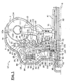
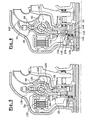
- a hydrokinetic coupling apparatus 10 as illustrated in FIG. figure 1 comprises, arranged in the same sealed housing, in two shell-shaped parts respectively before 2 and rear 1, filled with a fluid such as oil, a torque converter 14 and a locking clutch 16.
- the shells 1, 2 are preferably assembled by welding.
- the torque converter 14 comprises a rear impeller wheel 11, a front turbine wheel 12 and a central reaction wheel 13.
- the impeller wheel 11 comprises blades 11a which are carried by the rear shell 1 which is integral with waterproof front shell 2 drive.
- the shell 1 is adapted to be rotatably connected to a drive shaft A1.
- the turbine wheel 12 also comprises vanes 12a which face the blades 11a of the impeller wheel 11, and the turbine wheel 12 is rotatably connected to a turbine hub 18 which is able to be rotatably connected to a driven shaft A2, coaxial with the axis XX of the apparatus 10, here via a damping device 20.
- the driving shaft A1 is constituted by the crankshaft of the internal combustion engine of the vehicle, while the driven shaft A2 is constituted by the input shaft of the transmission of the vehicle. vehicle connected to gearshift means.
- the turbine wheel 12 is here secured in rotation, by a link without clearance, of the turbine hub 18.
- the connection between the turbine wheel 12 and the turbine hub 18 is here produced by friction welding, between a radial front surface 22 of the inner periphery of the turbine wheel 12 and a rear radial surface 24 of the turbine hub 18, axially vis-à-vis.
- connection between the turbine wheel 12 and the turbine hub 18 can also be achieved by other means, for example by riveting or crimping.
- the turbine hub 18 is provided to be rotatably connected to the driven shaft A2 via the damping device 20, or damper, which comprises an input member 26, 28 and an output member 29.
- the input element of the damper 20 is constituted by guide washers 26, 28, one of which, said guide rear washer 26, is linked in rotation without play by meshing with the turbine hub 18.
- the outer peripheral edge of the turbine hub 18 has teeth 30 which extend radially outward and which are provided to cooperate with teeth 32. complementary carried by the inner peripheral edge of the rear guide washer 26.
- the axial thickness of the teeth 30 of the turbine hub 18 is greater than the axial thickness of the teeth 32 of the rear guide washer 26, so that the rear guide washer 26 has an axial freedom to move forwards or backwards, while keeping contact by meshing between its teeth 32 and the teeth 30 of the turbine hub 18.
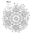
- the guide washers 26, 28 are secured to rotate from one another by their outer peripheral edges 34, 36, which comprise adjacent angular sectors 38 distributed regularly around the axis XX, as can be seen on the figure 2 .
- the adjacent angular sectors 38 are joined by their radial faces vis-à-vis, here by means of rivets 40.
- the contiguous angular sectors 38 circumferentially delimit between them guide and abutment notches 42, which are each provided to allow the angular displacement of an associated radial tab 44, formed in the radial extension of the outer peripheral edge 46 of a web 29 forming the output element of the damper 20.
- Each notch 42 has two circumferentially opposed radial edges 48, 50 which form abutment surfaces for the associated radial tab 44.
- the abutment of the radial lugs 44 against the abutment surfaces 48, 50 therefore determines a relative angular position of abutment between the guide washers 26, 28 and the veil 29.
- the torque transmitted by the turbine wheel 12 to the turbine hub 18 is transmitted to the guide washers 26, 28, forming the input element of the damper 20, then to the sail 29, forming the output element. of the damper 20, by means of elastic members with circumferential action 50, after an angular displacement of the guide washers 26, 28 to their angular position of abutment with the web 29.
- the elastic members 50 with circumferential action are interposed between the guide washers 26, 28 and the web 29. To do this, the web 29 has windows 52 in which the elastic members 50 are mounted.
- the guide washers 26, 28 also each comprise a central guide portion 54, 56 which is provided with windows 58, 60 arranged in line with the windows 52 of the web 29.
- the elastic members 50 are respectively bearing on the radial edges 62, 64 of the windows 58, 60 of the guide washers 26, 28 and on the radial edges 66, 68 of the windows 52 of the web 29.
- the elastic members 50 are held axially by the circumferentially oriented edges of the windows 58, 60 of the guide washers 26, 28.
- the elastic members 50 are thus circumferentially biased between the input elements 26, 28 and output 29 of the damper 20, to the extent of a relative angular displacement determined by the circumferential displacement of the radial tabs 44 of the sail 29 in the notches 42 of the guide washers 26, 28, to an angular position of abutment.
- the web 29 is integral in rotation, meshing without play, with an outlet hub 70 which is rotatably connected, here via splines 72, with the driven shaft A2.
- the web 29, forming the output element of the damper 20 can be made in one piece with the outlet hub 70.
- the apparatus 10 comprises, in the front, a sealed chamber 74, which is delimited axially by the front shell 2 of the housing and by a piston 76.
- the piston 76 is axially movable so as to be able to clamp axially under the housing. action of the pressure of the oil in the chamber 74, the clutch 16, here multi-disk type.
- such a clutch 16 comprises a plurality of flanges 78 and friction discs 80, interposed axially between two successive flanges 78, each friction disc 80 being provided on its front and rear faces of friction linings.
- the flanges 78 comprise, at their outer radial periphery, a toothing or any other means adapted to rotate the shapes of the flanges 78 to a first connecting piece 82 by rotationally co-operating.
- the first connecting piece 82 is integral in rotation with the shell 2 on which it is for example reported by welding.
- the discs 80 comprise, in a similar manner to the flanges 78, meshing means, at their inner radial periphery, which provide the connection in rotation with a second connecting piece 84, which is integral in rotation with the inlet of the damper 20, for example of the front guide washer 28.
- the second connecting piece 84 here comprises a radial portion 86, at its rear axial end, which is fixed on the front face of the front guide washer 28 by means of rivets 88.
- the second connecting piece 84 may be fixed to the front guide washer 28 by other means, including friction welding.
- the piston 76 comprises, at its outer radial periphery, an annular groove in which are mounted first dynamic sealing means, such as a segment 90, which cooperates with an axial surface vis-à-vis the first piece of connection 82 and, at its inner radial periphery, a clean surface to cooperate with second dynamic sealing means, such as a segment 92, which is mounted in an annular groove of a hub, or centralizer 94, which surrounds the piston 76, with which it is connected in rotation by meshing.
- first dynamic sealing means such as a segment 90
- second dynamic sealing means such as a segment 92, which is mounted in an annular groove of a hub, or centralizer 94, which surrounds the piston 76, with which it is connected in rotation by meshing.
- the dynamic sealing means 90, 92 thus delimit the chamber 74, which is supplied with oil by a hollow shaft, here the driven shaft A2, adapted radial passages 96 being provided in the centralizer 94.
- the apparatus 10 is here of the "three-way" type, that is to say that it comprises a first channel V1 for supplying the hydraulic circuit of the converter 14 and a second channel V2 for output, and a third channel supply V3 of the chamber 74 to move the piston 76 axially, this third channel V3 being independent of the first V1 and second V2 channels of the converter 14.
- a first phase of operation in a first phase of operation, called “converter phase", the torque of the driving shaft A1 is transmitted to the impeller wheel 11 which drives, by circulation of oil between the blades 11a and 12a, the turbine wheel 12 .
- the damper 20 is practically not involved in the damping of vibrations or torsional oscillations resulting in particular from motor acyclisms. Indeed, the vibrations or torsional oscillations are filtered mainly in the oil by the converter 14, since the transmission of the engine torque is achieved by means of the kinetic energy of the oil in the converter 14, the damper 20 merely transmitting the torque of the turbine wheel 12 to the output hub 70.
- the sealed chamber 74 of the casing 1, 2 is fed in such a way that the piston 76 exerts an axial pressure towards the rear, against the clutch 16, under the action of the pressure of the oil in the chamber 74, to couple the A1 and A2 drive shafts.
- the clutch 16 is generally activated after the vehicle has been started and after the hydraulic coupling of the drive shafts A1 and A2, in order to avoid the loss of efficiency induced in particular by phenomena of slippage between the turbine wheels 12 and the impeller 11.
- the resilient members 50 dampen the torsional oscillations and, after angular displacement of the clearance connection between the guide washers 26, 28 and the web 29 of the damper 20, the torque is transmitted to the web 29, which is rotatably connected. to the driven shaft A2, through the hub 70.
- the apparatus 10 comprises means for restricting the circulation of the oil in a generally radial direction, at least within the axial space before E1, which is located between the front washer 28 and the sail 29, so as to promote the circulation of the oil, the supply path V1 to the escape route V2, through the locking clutch 16.
- the locking clutch 16 comprises for this purpose radial bores 98, which are formed in the first 82 and in the second 84 connecting pieces, so as to allow the radial circulation of the oil through the clutch 16, between the flanges 78 and the friction discs 80.
- the circulation of the oil through the clutch 16 makes it possible to cool the clutch 16, in particular when the clutch 16 is engaged, or semi-engaged, and that a slip occurs between the flanges 78 and the friction discs 80, producing a heating.
- the damper 20 comprises an axial elastic spring washer 100 which is interposed axially between the front guide washer 28 and the web 29.
- This elastic washer 100 is here a frustoconical washer which is substantially axially continuous, circumferentially, on each face facing each other, respectively of the front guide washer 28 and the web 29.
- the front elastic washer 100 is disposed radially inward with respect to the resilient members 50.
- the elastic washer before 100 thus forms a substantially sealed barrier, which prevents the circulation of the oil radially inwards, in the axial space before E1.
- the front guide washer 28 extends radially inwards, generally to the outlet hub 70.
- the axial bores 102, 104, 106 of each series are for example angularly distributed regularly.
- the axial bores 102 of the front guide washer 28 are arranged radially inward with respect to the front elastic washer 100.
- the turbine hub 18 here comprises grooves which extend radially in its front face and which allow the "connection" between the axial bores 104 of the web 29 and the axial bores 106, the latter being offset radially inwards, by relation to axial bores 104.
- the axial passages 106 may be made in the form of axial grooves, which are formed in the inner periphery of the turbine hub 18. These axial grooves are for example angularly distributed regularly.
- Such grooves can be made easily by machining, which reduces the manufacturing costs of the turbine hub 18.
- the front guide washer 28 comprises a rearward convex annular boss 108, which can be made by stamping, and which allows the centering of the elastic washer before 100.
- centering boss 108 may be interrupted circumferentially, so as to form angularly distributed centering sectors.
- the damping device 20 comprises a rear spring washer 110, of the same type as the front elastic washer 100, which is interposed axially in the rear axial space E2, between the sail 29 and the rear guide washer 26.
- the rear spring washer 110 is here arranged radially between the resilient members 50 and the teeth 32 of the rear guide washer 26.
- the rear spring washer 110 is here centered on the sail 29 by means of an axial recess 112 formed in the sail 29.
- the rear spring washer 110 forms a barrier against the flow of oil, which comes from the feed path V1, and which circulates between the damper 20 and the wheel turbine 12.
- the circulation of the oil in the apparatus 10 is illustrated on the figure 1 , by arrows.
- the spring washers 100, 110 contribute to the damping of the torsional oscillations in the apparatus 10, since they form friction elements between the guide washers 26, 28 and the web 29.
- the spring washers 100, 110 participate in the axial positioning of the elements of the damper 20 in the apparatus 10, compensating axial clearances.
- the seal is maintained, even in case of axial displacement of the web 29 relative to the guide washers 26, 28.
- the spring washers 100, 110 may be treated, for example by carbonitriding.
- edges of the spring washers 100, 110, which are in contact with the guide washer 26, 28 associated or with the web 29, are rounded, so as to avoid deterioration of the surfaces in contact.
- an oil flow can circulate in the rear axial space E2, passing between the teeth 30 of the turbine hub 18 and the teeth 32 of the rear guide washer 26.
- oil flow is low, since the rear guide washer 26 meshes without play on the turbine hub 18, and because the oil flow depends only on the radial clearance between the teeth 30, 32.
- the axial displacement of the rear guide washer 26, relative to the turbine hub 18, does not modify the passage section of the oil between the two elements 18, 26, unlike an apparatus 10 in which the teeth of the turbine hub 18 form pavers, which extend axially forwardly from the front radial surface of the turbine hub 18, such as the apparatuses shown in the documents FR-A-2765939 and US Patent 5,975,261 .
- This arrangement also makes it possible to reduce the production costs, in particular because it is easier to perform by machining radial teeth 30, 32, at the outer and inner periphery, respectively of the turbine hub 18 and the rear guide washer. 26, than to make teeth that extend axially forward, as in the documents cited above.
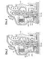
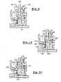
- a second embodiment which is represented on the figure 3 , provides for axially interposing the rear spring washer 110 between the web 29 and a radial front surface 114 of the turbine hub 18.
- the front face of the turbine hub 18 here comprises a countersink in which the rear spring washer 110 is centered by its inner radial periphery.
- the front face of the turbine hub 18, on which bears the rear spring washer 110 is treated for example by carbo-nitriding, so as to increase its hardness.
- This treatment can be performed, for example, at the same time as the treatment of the teeth 30.
- damper 20 comprises a single spring washer 100, in the axial space before E1, and wherein the turbine hub 18 has a continuous annular radial surface 116, which is provided to be in axial support forwards against the rear face of the veil 29.
- annular radial surface 116 of the turbine hub 18 being in continuous axial abutment against the web 29, this prevents the radial circulation of the oil inwards, in the rear axial space E2.
- the embodiment shown here is provided with an alternative embodiment of the centering means of the elastic washer before 100.
- the front guide washer 28 comprises several "keystrokes", which form on the rear face of the washer 28 centering reliefs 118, which are angularly distributed, preferably in a regular manner.
- the centering reliefs 118 are for example intercalated circumferentially between two rivets 88 for fixing the second connecting piece 84.
- the central guide portion 54, 56 of each guide ring 26, 28 is full, ie it has no window 58, 60.
- central guide portion 54, 56 of each guide ring 26, 28 thus forms, in line with the elastic members 50; complementary bosses 120 instead of windows 58, 60.
- the bosses 120 delimit, at each of their circumferential ends, a bearing surface 122, 124 for the elastic members 50, which generally has the same function as the radial edges 62, 64 of the windows 58, 60.
- the elastic members 50 comprise, in each window 52 of the web 29, a pair of coaxial coil springs 126, 128.
- the guide washers 26, 28 must therefore comprise, for each pair of springs 126, 128, two bearing surfaces, circumferentially opposed, on which the two springs 126, 128 can bear.
- each pair of springs 126, 128, two cups 130, 132 which abut against the bearing surfaces 122, 124 of the bosses 120, and which themselves form bearing surfaces for the springs 126, 128.
- the outer peripheral edge 34, 36 of each guide washer 26, 28 is continuous and adjacent to the outer peripheral edge 34, 36 vis-à-vis, so as to "close” the damper 20 at its outer periphery.
- each guide ring 26, 28 has angular sectors 38 which are riveted to the angular sectors 38 facing each other.
- the front guide washer 28 comprises angular sectors 134, which are interposed between two riveted angular sectors 38, and which each form a boss 136, convex towards the front, delimiting an axial space, between the two guide washers 26, 28, to allow the angular clearance of the radial tab 44 associated with the sail 29.
- the bosses 136 replace the circumferential notches 42.
- Each boss 136 is bounded radially outwards by a circumferential edge 138, which bears axially against the front face of the outer peripheral edge 34 opposite the rear guide washer 26.
- the outer peripheral edge 34 of the rear guide washer 26 is here substantially flat over its entire circumference, that is to say that the angular sectors 134 interposed between two riveted angular sectors 38 have no boss, vis-à-vis bosses 136 of the front guide washer 28.
- the realization of the guide washers 26, 28 is facilitated.
- the bosses 136 are only made in the front washer 28, so that, in view of manufacturing tolerances, in particular stamping, it is easier to ensure a substantially continuous contact between the edges.
- bosses 136 can be made both in the front washer 28 and in the rear guide washer 26, so that the outer peripheral edges 34, 36 of the two washers 26 , 28 are substantially symmetrical with respect to a plane of symmetry transverse to the axis XX.
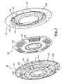
- the guide washers 26, 28 are closed, in line with the elastic members 50, as in the fourth embodiment, but the peripheral edges 34, 36 of the guide washers 26, 28 are made as in the first embodiment, that is to say they have notches 42 "open".
- front and rear spring washers 100, 110 of the same type as those of the first embodiment, which are interposed axially between the web 29 and the associated guide washer 26, 28, and which are arranged radially on the outside, with respect to the resilient members 50.
- FIG. 8 there is shown a fifth embodiment of the invention, which is similar to the previous one, but in which the rear guide washer 26 is similar to that of the third embodiment, which is shown in FIG. figure 4 .
- the rear guide washer 26 is therefore not full, but it includes windows 58 to the right of the elastic members 50.
- the outer peripheral edge 34 of the rear guide washer 26 extends axially rearwardly by a deflector 140 in the form of an axial skirt.
- Deflector 140 deflects the flow of oil to clutch 16.
- the deflector 140 is arranged to minimize the axial space between the outer periphery of the damper 20 and the turbine wheel 12, so that the majority of the oil flow flows towards the axial space between the front shell 2 and the outer periphery of the damper 20, to pass through the clutch 16.
- the deflector 140 may also equip an apparatus 10 in which the two guide washers 26, 28 are solid, such as that which is shown in FIGS. Figures 5 to 7 .
- the outlet hub 70 comprises, at the front, axial abutment means cooperating with a portion of the front face of the veil 29. and with a portion of the rear face of the front guide washer 28, so as to axially retain the damping device 20 on the output hub 70.
- These axial abutment means allow, during the operation of the apparatus 10, to limit the axial displacement of the web 29, relative to the output hub 70, forwards.
- axial abutment means also make it possible to assemble the damping device 20 on the outlet hub 70, before being mounted in the hydrokinetic coupling apparatus 10, so as to produce a subassembly which facilitates the transport of these elements 20, 70 to their place of installation in the hydrokinetic coupling apparatus 10.
- the outlet hub 70 has an abutment ring 142, or rod, which is mounted on the axial face 144 of its main section 146.
- Main section 146 is here referred to as the section of outlet hub 70 in which meshing teeth 148 are formed with teeth 150 of web 29.
- the abutment ring 142 here of circular axial section, is received in a peripheral groove 152 of the main section 146, arranged in the vicinity of the axial front end of the main section 146.
- the sail 29 When the sail 29 is mounted on the outlet hub 70, the sail 29 is retained axially forwardly, since it comprises, at its inner periphery, a radial surface portion 154 facing the ring axially. stop 142.
- the web 29 is also retained axially rearwardly. Indeed, the web 29 is "trapped" between the two guide washers 26, 28, and the front guide washer 28 has, at its inner periphery, a radial surface portion 156 vis-à-vis axially of the ring. abutment 142, and here vis-à-vis axially the outer peripheral edge of the radial surface before 158 of the main section 146. The radial surface portion 156 is therefore likely to abut axially rearwardly against the radial surface before 158 of the main section 146.
- the diameter of the inner periphery of the front guide washer 28 is smaller than the outside diameter of the main section 146 of the outlet hub 70, so that the radial surface portion 156 is arranged facing axially from the radial surface before 158 of the main section 146.
- a second embodiment of the axial stop means is represented on the figure 9 . -
- the stop ring 142 is replaced by a radial peripheral extension, or rim 160, at the axial front end of the main section 146 of the outlet hub 70.
- the flange 160 is formed on the main section 146, before the teeth 148.
- the teeth 148 are then produced over the entire axial thickness of the main section 146, so that the flange 160 then has a profile, in cross section, shaped teeth.
- each tooth 148 of the main section 146 then has, at its forward axial end, a small outer edge 160.
- the diameter of the inner periphery of the front guide washer 28 is such that the front guide washer 28 has a radial surface portion 156 facing axially, at least of the radial surface before the rim 160.
- the main section 146 of the output hub 70 has a flange 160 similar to that of the second embodiment.
- the apparatus 10 generally comprises bearing means 162 which are interposed axially between the centralizer 94 and the radial front surface 158 of the main section 146.
- These rolling means 162 here consist of a needle stop comprising elements mounted between two radial flanges before 164 and rear 166.
- the rear radial flange 166 is for example crimped on the output hub 70.
- the rear radial flange 166 has an outer radial extension 168, which is adjacent to the front radial surface 158 of the main section 146, and which extends outwardly beyond the flange 160.
- This third embodiment makes it possible in particular to increase the diameter of the opening formed by the inner periphery of the front guide washer 28, since the radial extension 168 forms an axial abutment surface, opposite the radial surface portion 156, which extends farther outward than the flange 160.
- the main section 146 of the output hub 70 has a stop ring 142 similar to that of the figure 8 , and a rear radial flange 166 similar to that of the figure 10 .
Landscapes
- Engineering & Computer Science (AREA)
- General Engineering & Computer Science (AREA)
- Mechanical Engineering (AREA)
- Mechanical Operated Clutches (AREA)
- Braking Arrangements (AREA)
- Yarns And Mechanical Finishing Of Yarns Or Ropes (AREA)
- Vibration Prevention Devices (AREA)
- Braking Systems And Boosters (AREA)
- Soft Magnetic Materials (AREA)
- Regulation Of General Use Transformers (AREA)
Claims (18)
- Hydrodynamischer Momentwandler (10), insbesondere für ein Kraftfahrzeug, umfassend:- ein Gehäuse (1, 2), gebildet aus einer ersten Schale (1), die eine Antriebswelle (A1) und ein Impulsrad (11) drehfest verbindet;- ein Turbinenrad (12), das durch eine spielfreie Verbindung drehfest mit einer Nabe (18) verbunden ist, die drehfest mit einer Abtriebswelle (A2) verbunden werden kann;- eine Verriegelungskupplung (16) zur Kupplung der Antriebswelle (A1) und der Abtriebswelle (A2), die einen Kolben (76) aufweist, der axial beweglich ist, um auskuppelbar eine zweite Schale (2) des Gehäuses mit der Abtriebswelle (A2) zu verbinden, indem zumindest eine Reibscheibe (80) eingespannt wird, die einerseits mit der zweiten Schale (2) des Gehäuses über einen ersten Verbindungsteil (82) und andererseits mit dem Eingangselement (26, 28) einer Dämpfvorrichtung (20) über einen zweiten Verbindungsteil (84) drehfest verbunden ist;wobei die Dämpfvorrichtung (20) in Umfangsrichtung wirksame elastische Organe (50) aufweist, die zwischen zwei Führungsscheiben (26, 28), die das Eingangselement bilden, und einen Flansch (29), der das Ausgangselement bildet und mit der Abtriebwelle (A2) drehfest verbunden ist, eingefügt sind, wobei das Eingangselement und das Ausgangselement mit einer Kapazität zur winkelmäßigen Auslenkung drehfest miteinander verbunden sind, die durch Anschlagmittel (38) begrenzt ist, und umfassend einen Versorgungskanal (V1) des Gehäuses mit Fluid und einen Ableitkanal (V2) des Fluids,
wobei die Dämpfvorrichtung (20) Mittel (100, 110, 116, 120, 138, 140) aufweist, um die Zirkulation des Fluids in eine insgesamt radiale Richtung zumindest im Inneren des vorderen Axialraums (E1) einzuschränken, der sich zwischen der vorderen Führungsscheibe (28) und dem Flansch (29) befindet, so dass die Zirkulation des Fluids von dem Versorgungskanal (V1) zu dem Ableitkanal (V2) durch die Verriegelungskupplung (16) begünstigt wird,
dadurch gekennzeichnet, dass die besagten Mittel zum Einschränken der Zirkulation des Fluids mindestens eine vordere elastische Scheibe (100) mit axialer Wirkung aufweisen, die axial zwischen den Flansch (29) und die vordere Führungsscheibe (28) derart eingefügt ist, dass eine Barriere gegen die radiale Zirkulation des Fluids im Inneren des vorderen Axialraums (E1) der Dämpfvorrichtung (20) gebildet wird, und/oder
mindestens eine hintere elastische Scheibe (110) mit axialer Wirkung aufweisen, die axial zwischen den Flansch (29) und eine nach hinten gegenüberliegende radiale Fläche eingefügt ist, und die im Verhältnis zu den elastischen Organen (50) radial innerhalb derart angeordnet ist, dass eine Barriere gegen die radiale Zirkulation des Fluids im Inneren des hinteren Axialraums (E2), der sich zwischen dem Flansch (29) und der hinteren Führungsscheibe (28) befindet, gebildet wird. - Momentwandler (10) nach Anspruch 1, dadurch gekennzeichnet, dass jede elastische Scheibe (100, 110) eine kegelstumpfförmige Scheibe ist.
- Momentwandler (10) nach einem der Ansprüche 1 oder 2, dadurch gekennzeichnet, dass die elastische Scheibe (100, 110) in Bezug auf die Achse mittels eines komplementären Zentrierprofils (108, 112, 114, 118), das in der dazugehörenden Führungsscheibe (26, 28) oder in dem Flansch (29) hergestellt ist, zentriert ist.
- Momentwandler (10) gemäß dem vorhergehenden Anspruch, dadurch gekennzeichnet, dass das Zentrierprofil mehrere Prägungen (118) aufweist, die auf der dazugehörenden Führungsscheibe (28) oder auf dem Flansch (29) winkelig verteilte Zentrierreliefs bilden.
- Momentwandler (10) nach einem der vorhergehenden Ansprüche, dadurch gekennzeichnet, dass die hintere Führungsscheibe (26) drehfest mit der Turbinennabe (18) verbunden ist.
- Momentwandler (10) nach dem vorhergehenden Anspruch, dadurch gekennzeichnet, dass die hintere Führungsscheibe (26) und die Turbinennabe (18) drehfest durch Verzahnen mittels Zähnen (30, 32) verbunden sind, die jeweils von dem Innenumfang der hinteren Führungsscheibe (26) und dem Außenumfang der Turbinennabe (18) getragen werden.
- Momentwandler (10) nach Anspruch 5 oder 6, dadurch gekennzeichnet, dass die Turbinennabe (18) eine kontinuierliche ringförmige radiale Fläche (116) aufweist, die gegen die hintere Fläche des Flanschs (29) derart zum axialen Aufliegen kommt, dass die radiale Zirkulation des Fluids im Inneren des hinteren Axialraums (E2) verhindert wird.
- Momentwandler (10) nach Anspruch 5 oder 6, in Kombination mit Anspruch 3, dadurch gekennzeichnet, dass die hintere elastische Scheibe (110) axial zwischen den Flansch (29) und die Vorderseite der Turbinennabe (18) eingefügt ist.
- Momentwandler (10) gemäß dem vorhergehenden Anspruch, dadurch gekennzeichnet, dass die Fläche (114) der Turbinennabe (18), die geeignet ist, mit der hinteren elastischen Scheibe (110) in Berührung zu kommen, und/oder die elastische Scheibe (110) zum Steigern ihrer Härte behandelt ist.
- Momentwandler (10) nach einem der vorhergehenden Ansprüche, dadurch gekennzeichnet, dass der zentrale Teil (54) der vorderen Führungsscheibe (28) und/oder der zentrale Teil (56) der hinteren Führungsscheibe (26), der den elastischen Organen (50) gegenüberliegt, geschlossen ist, so dass das Fluid nicht durch Durchqueren des zentralen Teils (54, 56) der Führungsscheibe (26, 28) in dem dazugehörenden Axialraum (E1, E2) zirkulieren kann.
- Momentwandler (10) nach dem vorhergehenden Anspruch, dadurch gekennzeichnet, dass die Dämpfvorrichtung (20) Schalenpaare (130, 132) aufweist, die in den zentralen Teilen (54, 56) der Führungsscheiben (26, 28) derart angeordnet sind, dass sie Auflageflächen für die in Umfangsrichtung wirksamen elastischen Organe (50) bilden.
- Momentwandler (10) nach einem der vorhergehenden Ansprüche, dadurch gekennzeichnet, dass jede Führungsscheibe (26, 28) einen kontinuierlichen äußeren Umfangsrand (34, 36) aufweist, und dass die zwei äußeren Ränder (34, 36) nebeneinander liegen, so dass sie den äußeren Umfang der Dämpfvorrichtung (20) schließen.
- Momentwandler (10) nach einem der vorhergehenden Ansprüche, dadurch gekennzeichnet, dass sich der äußere Umfang (34) einer der Führungsscheiben (26) axial nach hinten durch einen Ablenker (140) verlängert, der den Ölstrom zu der Kupplung (16) umlenkt.
- Momentwandler (10) nach dem vorhergehenden Anspruch, dadurch gekennzeichnet, dass der Ablenker (140) eine axiale Schürze bildet, die den Axialraum zwischen dem äußeren Umfang der Dämpfvorrichtung (20) und dem Turbinenrad (12) minimiert.
- Momentwandler (10) nach Anspruch 13 oder 14, dadurch gekennzeichnet, dass der Ablenker (140) durch eine einstückig ausgeführte äußere radiale Erweiterung der hinteren Führungsscheibe (26) gebildet ist.
- Momentwandler (10) nach einem der vorhergehenden Ansprüche, dadurch gekennzeichnet, dass die vordere Führungsscheibe (28) und der Flansch (29) jeweils axiale Bohrungen (102, 104) aufweisen, die insgesamt axial einander gegenüberliegend angeordnet sind, um die Zirkulation des Ölstroms, der die Kupplung (16) durchquert hat, zu dem Ableitkanal (V2) zu erleichtern.
- Momentwandler (10) nach einem der vorhergehenden Ansprüche, dadurch gekennzeichnet, dass die Turbinennabe (18) axiale Durchgänge (106) in der Nähe ihres Innenumfangs aufweist, um die Zirkulation des Ölstroms, der die Kupplung (16) durchquert hat, zu dem Ableitkanal (V2) zu erleichtern.
- Momentwandler (10) nach dem vorhergehenden Anspruch, dadurch gekennzeichnet, dass die axialen Durchgänge (106) in Form axialer Hohlkehlen hergestellt sind.
Applications Claiming Priority (3)
| Application Number | Priority Date | Filing Date | Title |
|---|---|---|---|
| FR0209974 | 2002-08-06 | ||
| FR0209974A FR2843433B1 (fr) | 2002-08-06 | 2002-08-06 | Appareil d'accouplement hydrocinetique, notamment pour un vehicule automobile |
| PCT/FR2003/002470 WO2004015307A1 (fr) | 2002-08-06 | 2003-08-06 | Appareil d'accouplement hydrocinetique, notamment pour un vehicule automobile. |
Publications (2)
| Publication Number | Publication Date |
|---|---|
| EP1527292A1 EP1527292A1 (de) | 2005-05-04 |
| EP1527292B1 true EP1527292B1 (de) | 2008-03-19 |
Family
ID=30470947
Family Applications (1)
| Application Number | Title | Priority Date | Filing Date |
|---|---|---|---|
| EP03756526A Expired - Lifetime EP1527292B1 (de) | 2002-08-06 | 2003-08-06 | Drehmomentwandler für fahrzeug |
Country Status (10)
| Country | Link |
|---|---|
| US (1) | US7708126B2 (de) |
| EP (1) | EP1527292B1 (de) |
| JP (1) | JP4370249B2 (de) |
| KR (1) | KR100993704B1 (de) |
| CN (1) | CN100398875C (de) |
| AT (1) | ATE389828T1 (de) |
| AU (1) | AU2003282526A1 (de) |
| DE (1) | DE60319834T2 (de) |
| FR (1) | FR2843433B1 (de) |
| WO (1) | WO2004015307A1 (de) |
Families Citing this family (20)
| Publication number | Priority date | Publication date | Assignee | Title |
|---|---|---|---|---|
| DE10347782B4 (de) * | 2003-10-15 | 2016-03-03 | Zf Friedrichshafen Ag | Hydrodynamischer Drehmomentwandler |
| DE102004024004B4 (de) * | 2004-05-14 | 2017-01-26 | Daimler Ag | Hydrodynamischer Drehmomentwandler |
| FR2871109B1 (fr) * | 2004-06-03 | 2006-09-22 | Peugeot Citroen Automobiles Sa | Module de transmission pour un groupe motopropulseur, notamment pour vehicules automobiles |
| JP5126067B2 (ja) * | 2006-01-12 | 2013-01-23 | シェフラー テクノロジーズ アクチエンゲゼルシャフト ウント コンパニー コマンディートゲゼルシャフト | 強制オイルガイドを備えたコンバータ |
| JP4944624B2 (ja) * | 2007-01-22 | 2012-06-06 | 本田技研工業株式会社 | 流体伝動装置 |
| JP5078477B2 (ja) * | 2007-07-20 | 2012-11-21 | 株式会社エクセディ | ロックアップダンパー |
| DE102009051248B4 (de) * | 2008-11-13 | 2019-03-28 | Schaeffler Technologies AG & Co. KG | Kraftübertragungsvorrichtung |
| US8939860B2 (en) * | 2010-05-25 | 2015-01-27 | Zf Friedrichshafen Ag | Hydrodynamic coupling device, in particular a torque converter |
| CN103228955B (zh) * | 2010-11-24 | 2015-03-04 | 丰田自动车株式会社 | 车辆用动力传递装置 |
| US8499912B2 (en) * | 2010-12-15 | 2013-08-06 | GM Global Technology Operations LLC | Torque converter with lock-up clutch |
| FR2974871B1 (fr) * | 2011-05-04 | 2013-05-17 | Valeo Embrayages | Dispositif d'amortissement de torsion comportant des organes elastiques dont chacun est maintenu individuellement en position par une rondelle de phasage |
| DE102014213618A1 (de) * | 2014-07-14 | 2016-01-14 | Schaeffler Technologies AG & Co. KG | Nassraum-Rotationsbauteil, Nassraum-Baugruppe sowie Drehmomentübertragungseinrichtung |
| US10844939B2 (en) | 2015-12-18 | 2020-11-24 | Schaeffler Technologies AG & Co. KG | Reduced volume torque converter having inverted cover closure |
| JP6674354B2 (ja) * | 2016-08-31 | 2020-04-01 | アイシン・エィ・ダブリュ工業株式会社 | 発進装置およびその製造方法 |
| US10451158B2 (en) * | 2017-11-06 | 2019-10-22 | Schaeffler Technologies AG & Co. KG | Torque converter configured for cross-flow to pressure chambers |
| US11592092B1 (en) * | 2021-11-15 | 2023-02-28 | Schaeffler Technologies AG & Co. KG | Torque converter with balanced turbine thrust loading |
| KR102594503B1 (ko) * | 2021-11-25 | 2023-10-27 | 주식회사 카펙발레오 | 토셔널 댐퍼 및 이를 구비한 하이브리드 구동 모듈 |
| KR102595942B1 (ko) | 2021-11-25 | 2023-10-31 | 주식회사 카펙발레오 | 토셔널 댐퍼 및 이를 구비한 하이브리드 구동 모듈 |
| KR102552733B1 (ko) * | 2022-02-14 | 2023-07-06 | 주식회사 카펙발레오 | 차량용 토크 컨버터 |
| US12398793B2 (en) * | 2023-12-07 | 2025-08-26 | Schaeffler Technologies AG & Co. KG | Torque converter with floating hub |
Family Cites Families (11)
| Publication number | Priority date | Publication date | Assignee | Title |
|---|---|---|---|---|
| US4949822A (en) * | 1989-07-20 | 1990-08-21 | Ford Motor Company | Torque converter assembly with reverse acting bypass clutch |
| DE4420959B4 (de) * | 1993-07-09 | 2006-05-11 | Luk Gs Verwaltungs Kg | Hydrodynamischer Strömungswandler |
| JP3854661B2 (ja) * | 1996-05-29 | 2006-12-06 | 株式会社エクセディ | ロックアップ装置付きトルクコンバータ |
| DE19724973C1 (de) * | 1997-06-13 | 1998-10-15 | Daimler Benz Ag | Anordnung einer 2-Wege-Torsionsdämpfereinheit und einer Kupplung in einem hydrodynamischen Drehmomentwandler |
| DE19881263B4 (de) * | 1997-08-11 | 2011-01-05 | Luk Gs Verwaltungs Kg | Hydrodynamischer Drehmomentwandler |
| DE19881220B4 (de) * | 1997-08-26 | 2015-10-01 | Schaeffler Technologies AG & Co. KG | Hydrodynamischer Drehmomentwandler |
| US6244401B1 (en) * | 1998-05-06 | 2001-06-12 | Luk Getriebe-Systeme Gmbh | Force transmitting apparatus |
| US6231472B1 (en) * | 1998-08-27 | 2001-05-15 | Mannesmann Sachs Ag | Torsional vibration damper in a lockup clutch with planetary gear set |
| US5975561A (en) | 1998-12-04 | 1999-11-02 | Trw Inc. | Steering shaft attachment |
| DE10212281B4 (de) * | 2002-03-20 | 2011-12-22 | Zf Sachs Ag | Hydrodynamische Kopplungseinrichtung |
| DE10350935B4 (de) * | 2002-11-16 | 2019-02-21 | Schaeffler Technologies AG & Co. KG | Drehmomentwandler |
-
2002
- 2002-08-06 FR FR0209974A patent/FR2843433B1/fr not_active Expired - Lifetime
-
2003
- 2003-08-06 CN CNB038190095A patent/CN100398875C/zh not_active Expired - Fee Related
- 2003-08-06 KR KR1020057002216A patent/KR100993704B1/ko not_active Expired - Fee Related
- 2003-08-06 AU AU2003282526A patent/AU2003282526A1/en not_active Abandoned
- 2003-08-06 EP EP03756526A patent/EP1527292B1/de not_active Expired - Lifetime
- 2003-08-06 JP JP2004526979A patent/JP4370249B2/ja not_active Expired - Fee Related
- 2003-08-06 AT AT03756526T patent/ATE389828T1/de not_active IP Right Cessation
- 2003-08-06 WO PCT/FR2003/002470 patent/WO2004015307A1/fr not_active Ceased
- 2003-08-06 US US10/523,826 patent/US7708126B2/en active Active
- 2003-08-06 DE DE60319834T patent/DE60319834T2/de not_active Expired - Lifetime
Also Published As
| Publication number | Publication date |
|---|---|
| FR2843433A1 (fr) | 2004-02-13 |
| CN1675483A (zh) | 2005-09-28 |
| FR2843433B1 (fr) | 2005-04-01 |
| US20090223767A1 (en) | 2009-09-10 |
| WO2004015307A1 (fr) | 2004-02-19 |
| KR100993704B1 (ko) | 2010-11-10 |
| US7708126B2 (en) | 2010-05-04 |
| KR20050054915A (ko) | 2005-06-10 |
| DE60319834T2 (de) | 2009-04-09 |
| JP4370249B2 (ja) | 2009-11-25 |
| JP2005534880A (ja) | 2005-11-17 |
| ATE389828T1 (de) | 2008-04-15 |
| EP1527292A1 (de) | 2005-05-04 |
| CN100398875C (zh) | 2008-07-02 |
| AU2003282526A1 (en) | 2004-02-25 |
| DE60319834D1 (de) | 2008-04-30 |
Similar Documents
| Publication | Publication Date | Title |
|---|---|---|
| EP1527292B1 (de) | Drehmomentwandler für fahrzeug | |
| EP2149726B2 (de) | Verschlusskupplung eines Geräts zur hydrokinetischen Ankupplung, das über perfektionierte Verbindungsmittel verfügt | |
| FR2922619A1 (fr) | Dispositif d'accouplement hydrocinetique comportant un embrayage de verrouillage multi-disques equipe de moyens elastiques de precontrainte circonferentielle | |
| FR2765939A1 (fr) | Convertisseur de couple hydrodynamique | |
| FR2749359A1 (fr) | Plaque de friction humide, mecanisme de transmission et d'interruption de puissance humide, embrayage humide et embrayage a verrouillage | |
| FR2797014A1 (fr) | Appareil d'accouplement hydrocinetique | |
| EP2149727B1 (de) | Hydrokinetisches Kupplungsgerät, das eine Verschlusskupplung mit perfektionierten progressiven Mitteln umfasst | |
| CA2288220C (fr) | Appareil d'accouplement hydrocinetique, notamment pour vehicule automobile | |
| WO2002001092A1 (fr) | Appareil d'accouplement hydrocinetique, notamment pour vehicule automobile, comportant des moyens perfectionnes de liaison du piston au couvercle | |
| WO2000019126A1 (fr) | Embrayage de verrouillage pour appareil d'accouplement hydrocinetique | |
| FR2922620A1 (fr) | Dispositif d'accouplement hydrocinetique comportant un disque de friction qui est porte par un element de liaison en rotation d'une roue de turbine avec un voile d'amortisseur | |
| WO1997042432A1 (fr) | Appareil d'accouplement hydrocinetique a piece d'entrainement de languettes, notamment pour vehicule automobile | |
| WO1997042433A1 (fr) | Appareil d'accouplement hydrocinetique a piece d'entrainement de languettes, notamment pour vehicule automobile | |
| WO1999001682A1 (fr) | Appareil d'accouplement hydrocinetique a embrayage de verrouillage, pour vehicule automobile | |
| EP2098756B1 (de) | Dämpfungsvorrichtung, die ein Schwingungsdämpfungssystem umfasst, das aus einer Trägheitstrommel besteht | |
| EP1723351B1 (de) | Hydrokinetische kupplungsvorrichtung, insbesondere für kraftfahrzeug | |
| EP1633997B1 (de) | Hydrokinetische kupplungsvorrichtung beispielsweise für ein kraftfahrzeug | |
| FR2816019A1 (fr) | Appareil d'accouplement hydrocinetique, notamment pour vehicule automobile | |
| WO2017220735A1 (fr) | Embrayage hydrocinetique pour un vehicule automobile | |
| EP2113687B1 (de) | Hydrokinetisches Kupplungsgerät, insbesondere für Kraftfahrzeug | |
| WO2018104139A1 (fr) | Dispositif d'amortissement de torsion | |
| FR2825770A1 (fr) | Appareil d'accouplement hydrocinetique, notamment pour vehicule automobile | |
| FR2766894A1 (fr) | Appareil d'accouplement hydrocinetique a piece d'entrainement de languettes, notamment pour vehicule automobile | |
| FR2734038A1 (fr) | Appareil d'accouplement hydrocinetique, notamment pour vehicule automobile | |
| FR2928432A3 (fr) | Dispositif d'amortissement comportant des moyens de butee perfectionnee. |
Legal Events
| Date | Code | Title | Description |
|---|---|---|---|
| PUAI | Public reference made under article 153(3) epc to a published international application that has entered the european phase |
Free format text: ORIGINAL CODE: 0009012 |
|
| 17P | Request for examination filed |
Effective date: 20050106 |
|
| AK | Designated contracting states |
Kind code of ref document: A1 Designated state(s): AT BE BG CH CY CZ DE DK EE ES FI FR GB GR IE IT LI LU MC NL PT SE SI SK TR |
|
| AX | Request for extension of the european patent |
Extension state: AL LT LV MK |
|
| DAX | Request for extension of the european patent (deleted) | ||
| 17Q | First examination report despatched |
Effective date: 20061222 |
|
| GRAP | Despatch of communication of intention to grant a patent |
Free format text: ORIGINAL CODE: EPIDOSNIGR1 |
|
| GRAS | Grant fee paid |
Free format text: ORIGINAL CODE: EPIDOSNIGR3 |
|
| GRAA | (expected) grant |
Free format text: ORIGINAL CODE: 0009210 |
|
| AK | Designated contracting states |
Kind code of ref document: B1 Designated state(s): AT BE BG CH CY CZ DE DK EE ES FI FR GB GR IE IT LI LU MC NL PT SE SI SK TR |
|
| REG | Reference to a national code |
Ref country code: GB Ref legal event code: FG4D Free format text: NOT ENGLISH |
|
| REG | Reference to a national code |
Ref country code: CH Ref legal event code: EP |
|
| REF | Corresponds to: |
Ref document number: 60319834 Country of ref document: DE Date of ref document: 20080430 Kind code of ref document: P |
|
| REG | Reference to a national code |
Ref country code: IE Ref legal event code: FG4D Free format text: LANGUAGE OF EP DOCUMENT: FRENCH |
|
| PG25 | Lapsed in a contracting state [announced via postgrant information from national office to epo] |
Ref country code: FI Free format text: LAPSE BECAUSE OF FAILURE TO SUBMIT A TRANSLATION OF THE DESCRIPTION OR TO PAY THE FEE WITHIN THE PRESCRIBED TIME-LIMIT Effective date: 20080319 |
|
| PG25 | Lapsed in a contracting state [announced via postgrant information from national office to epo] |
Ref country code: AT Free format text: LAPSE BECAUSE OF FAILURE TO SUBMIT A TRANSLATION OF THE DESCRIPTION OR TO PAY THE FEE WITHIN THE PRESCRIBED TIME-LIMIT Effective date: 20080319 |
|
| NLV1 | Nl: lapsed or annulled due to failure to fulfill the requirements of art. 29p and 29m of the patents act | ||
| PG25 | Lapsed in a contracting state [announced via postgrant information from national office to epo] |
Ref country code: SI Free format text: LAPSE BECAUSE OF FAILURE TO SUBMIT A TRANSLATION OF THE DESCRIPTION OR TO PAY THE FEE WITHIN THE PRESCRIBED TIME-LIMIT Effective date: 20080319 |
|
| REG | Reference to a national code |
Ref country code: IE Ref legal event code: FD4D |
|
| PG25 | Lapsed in a contracting state [announced via postgrant information from national office to epo] |
Ref country code: PT Free format text: LAPSE BECAUSE OF FAILURE TO SUBMIT A TRANSLATION OF THE DESCRIPTION OR TO PAY THE FEE WITHIN THE PRESCRIBED TIME-LIMIT Effective date: 20080826 Ref country code: ES Free format text: LAPSE BECAUSE OF FAILURE TO SUBMIT A TRANSLATION OF THE DESCRIPTION OR TO PAY THE FEE WITHIN THE PRESCRIBED TIME-LIMIT Effective date: 20080630 Ref country code: SK Free format text: LAPSE BECAUSE OF FAILURE TO SUBMIT A TRANSLATION OF THE DESCRIPTION OR TO PAY THE FEE WITHIN THE PRESCRIBED TIME-LIMIT Effective date: 20080319 Ref country code: SE Free format text: LAPSE BECAUSE OF FAILURE TO SUBMIT A TRANSLATION OF THE DESCRIPTION OR TO PAY THE FEE WITHIN THE PRESCRIBED TIME-LIMIT Effective date: 20080619 Ref country code: CZ Free format text: LAPSE BECAUSE OF FAILURE TO SUBMIT A TRANSLATION OF THE DESCRIPTION OR TO PAY THE FEE WITHIN THE PRESCRIBED TIME-LIMIT Effective date: 20080319 |
|
| PG25 | Lapsed in a contracting state [announced via postgrant information from national office to epo] |
Ref country code: NL Free format text: LAPSE BECAUSE OF FAILURE TO SUBMIT A TRANSLATION OF THE DESCRIPTION OR TO PAY THE FEE WITHIN THE PRESCRIBED TIME-LIMIT Effective date: 20080319 |
|
| PLBE | No opposition filed within time limit |
Free format text: ORIGINAL CODE: 0009261 |
|
| STAA | Information on the status of an ep patent application or granted ep patent |
Free format text: STATUS: NO OPPOSITION FILED WITHIN TIME LIMIT |
|
| PG25 | Lapsed in a contracting state [announced via postgrant information from national office to epo] |
Ref country code: IE Free format text: LAPSE BECAUSE OF FAILURE TO SUBMIT A TRANSLATION OF THE DESCRIPTION OR TO PAY THE FEE WITHIN THE PRESCRIBED TIME-LIMIT Effective date: 20080319 Ref country code: DK Free format text: LAPSE BECAUSE OF FAILURE TO SUBMIT A TRANSLATION OF THE DESCRIPTION OR TO PAY THE FEE WITHIN THE PRESCRIBED TIME-LIMIT Effective date: 20080319 |
|
| 26N | No opposition filed |
Effective date: 20081222 |
|
| PG25 | Lapsed in a contracting state [announced via postgrant information from national office to epo] |
Ref country code: MC Free format text: LAPSE BECAUSE OF NON-PAYMENT OF DUE FEES Effective date: 20080831 |
|
| REG | Reference to a national code |
Ref country code: CH Ref legal event code: PL |
|
| GBPC | Gb: european patent ceased through non-payment of renewal fee |
Effective date: 20080806 |
|
| PG25 | Lapsed in a contracting state [announced via postgrant information from national office to epo] |
Ref country code: EE Free format text: LAPSE BECAUSE OF FAILURE TO SUBMIT A TRANSLATION OF THE DESCRIPTION OR TO PAY THE FEE WITHIN THE PRESCRIBED TIME-LIMIT Effective date: 20080319 Ref country code: BG Free format text: LAPSE BECAUSE OF FAILURE TO SUBMIT A TRANSLATION OF THE DESCRIPTION OR TO PAY THE FEE WITHIN THE PRESCRIBED TIME-LIMIT Effective date: 20080619 |
|
| REG | Reference to a national code |
Ref country code: FR Ref legal event code: ST Effective date: 20090430 |
|
| PG25 | Lapsed in a contracting state [announced via postgrant information from national office to epo] |
Ref country code: LI Free format text: LAPSE BECAUSE OF NON-PAYMENT OF DUE FEES Effective date: 20080831 Ref country code: CH Free format text: LAPSE BECAUSE OF NON-PAYMENT OF DUE FEES Effective date: 20080831 |
|
| PG25 | Lapsed in a contracting state [announced via postgrant information from national office to epo] |
Ref country code: BE Free format text: LAPSE BECAUSE OF NON-PAYMENT OF DUE FEES Effective date: 20080831 |
|
| PG25 | Lapsed in a contracting state [announced via postgrant information from national office to epo] |
Ref country code: FR Free format text: LAPSE BECAUSE OF NON-PAYMENT OF DUE FEES Effective date: 20080901 Ref country code: IT Free format text: LAPSE BECAUSE OF FAILURE TO SUBMIT A TRANSLATION OF THE DESCRIPTION OR TO PAY THE FEE WITHIN THE PRESCRIBED TIME-LIMIT Effective date: 20080319 |
|
| PG25 | Lapsed in a contracting state [announced via postgrant information from national office to epo] |
Ref country code: CY Free format text: LAPSE BECAUSE OF FAILURE TO SUBMIT A TRANSLATION OF THE DESCRIPTION OR TO PAY THE FEE WITHIN THE PRESCRIBED TIME-LIMIT Effective date: 20080319 |
|
| PG25 | Lapsed in a contracting state [announced via postgrant information from national office to epo] |
Ref country code: GB Free format text: LAPSE BECAUSE OF NON-PAYMENT OF DUE FEES Effective date: 20080806 |
|
| PG25 | Lapsed in a contracting state [announced via postgrant information from national office to epo] |
Ref country code: LU Free format text: LAPSE BECAUSE OF NON-PAYMENT OF DUE FEES Effective date: 20080806 |
|
| PG25 | Lapsed in a contracting state [announced via postgrant information from national office to epo] |
Ref country code: TR Free format text: LAPSE BECAUSE OF FAILURE TO SUBMIT A TRANSLATION OF THE DESCRIPTION OR TO PAY THE FEE WITHIN THE PRESCRIBED TIME-LIMIT Effective date: 20080319 |
|
| PG25 | Lapsed in a contracting state [announced via postgrant information from national office to epo] |
Ref country code: GR Free format text: LAPSE BECAUSE OF FAILURE TO SUBMIT A TRANSLATION OF THE DESCRIPTION OR TO PAY THE FEE WITHIN THE PRESCRIBED TIME-LIMIT Effective date: 20080620 |
|
| PGFP | Annual fee paid to national office [announced via postgrant information from national office to epo] |
Ref country code: DE Payment date: 20210811 Year of fee payment: 19 |
|
| REG | Reference to a national code |
Ref country code: DE Ref legal event code: R082 Ref document number: 60319834 Country of ref document: DE Representative=s name: PRINZ & PARTNER MBB PATENTANWAELTE RECHTSANWAE, DE |
|
| REG | Reference to a national code |
Ref country code: DE Ref legal event code: R119 Ref document number: 60319834 Country of ref document: DE |
|
| PG25 | Lapsed in a contracting state [announced via postgrant information from national office to epo] |
Ref country code: DE Free format text: LAPSE BECAUSE OF NON-PAYMENT OF DUE FEES Effective date: 20230301 |