EP1527292B1 - Hydrokinetic coupling device intended, in particular, for a motor vehicle - Google Patents
Hydrokinetic coupling device intended, in particular, for a motor vehicle Download PDFInfo
- Publication number
- EP1527292B1 EP1527292B1 EP03756526A EP03756526A EP1527292B1 EP 1527292 B1 EP1527292 B1 EP 1527292B1 EP 03756526 A EP03756526 A EP 03756526A EP 03756526 A EP03756526 A EP 03756526A EP 1527292 B1 EP1527292 B1 EP 1527292B1
- Authority
- EP
- European Patent Office
- Prior art keywords
- web
- axial
- washer
- guide washer
- radial
- Prior art date
- Legal status (The legal status is an assumption and is not a legal conclusion. Google has not performed a legal analysis and makes no representation as to the accuracy of the status listed.)
- Expired - Lifetime
Links
Images

Classifications
-
- F—MECHANICAL ENGINEERING; LIGHTING; HEATING; WEAPONS; BLASTING
- F16—ENGINEERING ELEMENTS AND UNITS; GENERAL MEASURES FOR PRODUCING AND MAINTAINING EFFECTIVE FUNCTIONING OF MACHINES OR INSTALLATIONS; THERMAL INSULATION IN GENERAL
- F16H—GEARING
- F16H45/00—Combinations of fluid gearings for conveying rotary motion with couplings or clutches
- F16H45/02—Combinations of fluid gearings for conveying rotary motion with couplings or clutches with mechanical clutches for bridging a fluid gearing of the hydrokinetic type
- F16H2045/021—Combinations of fluid gearings for conveying rotary motion with couplings or clutches with mechanical clutches for bridging a fluid gearing of the hydrokinetic type three chamber system, i.e. comprising a separated, closed chamber specially adapted for actuating a lock-up clutch
-
- F—MECHANICAL ENGINEERING; LIGHTING; HEATING; WEAPONS; BLASTING
- F16—ENGINEERING ELEMENTS AND UNITS; GENERAL MEASURES FOR PRODUCING AND MAINTAINING EFFECTIVE FUNCTIONING OF MACHINES OR INSTALLATIONS; THERMAL INSULATION IN GENERAL
- F16H—GEARING
- F16H45/00—Combinations of fluid gearings for conveying rotary motion with couplings or clutches
- F16H45/02—Combinations of fluid gearings for conveying rotary motion with couplings or clutches with mechanical clutches for bridging a fluid gearing of the hydrokinetic type
- F16H2045/0221—Combinations of fluid gearings for conveying rotary motion with couplings or clutches with mechanical clutches for bridging a fluid gearing of the hydrokinetic type with damping means
- F16H2045/0247—Combinations of fluid gearings for conveying rotary motion with couplings or clutches with mechanical clutches for bridging a fluid gearing of the hydrokinetic type with damping means having a turbine with hydrodynamic damping means
-
- F—MECHANICAL ENGINEERING; LIGHTING; HEATING; WEAPONS; BLASTING
- F16—ENGINEERING ELEMENTS AND UNITS; GENERAL MEASURES FOR PRODUCING AND MAINTAINING EFFECTIVE FUNCTIONING OF MACHINES OR INSTALLATIONS; THERMAL INSULATION IN GENERAL
- F16H—GEARING
- F16H45/00—Combinations of fluid gearings for conveying rotary motion with couplings or clutches
- F16H45/02—Combinations of fluid gearings for conveying rotary motion with couplings or clutches with mechanical clutches for bridging a fluid gearing of the hydrokinetic type
- F16H2045/0273—Combinations of fluid gearings for conveying rotary motion with couplings or clutches with mechanical clutches for bridging a fluid gearing of the hydrokinetic type characterised by the type of the friction surface of the lock-up clutch
- F16H2045/0284—Multiple disk type lock-up clutch
Definitions
- the present invention relates to a hydrokinetic coupling apparatus, in particular for a motor vehicle.
- An apparatus according to the preamble of the independent claim is known from the document US-B-6354413 .
- hydrokinetic coupling devices are of the "three-way" type, that is to say that the hydraulic circuit of each apparatus comprises a first channel for supplying fluid to the converter, a second escape route, and a third channel, independent of the first and second channels of the converter, which supplies the control chamber of the piston of the clutch. locking device, in order to axially move the piston.
- the supply path brings the fluid into the converter, between the impeller wheel and the turbine wheel, and the fluid is removed from the converter from the outside, passing in the radial space between the turbine wheel and the second shell of the housing.
- the fluid then circulates radially inwards, in the axial space between the turbine and the second shell, to be evacuated by the escape route, which is for example arranged between the driven shaft and a reaction sleeve carrying a central reaction wheel.
- the fluid passes radially through the locking clutch, which has radial openings for this purpose, and it circulates radially and axially inside the damping device.
- the invention aims in particular to remedy this drawback by proposing a simple and economical solution.
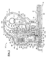
- a hydrokinetic coupling apparatus 10 as illustrated in FIG. figure 1 comprises, arranged in the same sealed housing, in two shell-shaped parts respectively before 2 and rear 1, filled with a fluid such as oil, a torque converter 14 and a locking clutch 16.
- the shells 1, 2 are preferably assembled by welding.
- the torque converter 14 comprises a rear impeller wheel 11, a front turbine wheel 12 and a central reaction wheel 13.
- the impeller wheel 11 comprises blades 11a which are carried by the rear shell 1 which is integral with waterproof front shell 2 drive.
- the shell 1 is adapted to be rotatably connected to a drive shaft A1.
- the turbine wheel 12 also comprises vanes 12a which face the blades 11a of the impeller wheel 11, and the turbine wheel 12 is rotatably connected to a turbine hub 18 which is able to be rotatably connected to a driven shaft A2, coaxial with the axis XX of the apparatus 10, here via a damping device 20.
- the driving shaft A1 is constituted by the crankshaft of the internal combustion engine of the vehicle, while the driven shaft A2 is constituted by the input shaft of the transmission of the vehicle. vehicle connected to gearshift means.
- the turbine wheel 12 is here secured in rotation, by a link without clearance, of the turbine hub 18.
- the connection between the turbine wheel 12 and the turbine hub 18 is here produced by friction welding, between a radial front surface 22 of the inner periphery of the turbine wheel 12 and a rear radial surface 24 of the turbine hub 18, axially vis-à-vis.
- connection between the turbine wheel 12 and the turbine hub 18 can also be achieved by other means, for example by riveting or crimping.
- the turbine hub 18 is provided to be rotatably connected to the driven shaft A2 via the damping device 20, or damper, which comprises an input member 26, 28 and an output member 29.
- the input element of the damper 20 is constituted by guide washers 26, 28, one of which, said guide rear washer 26, is linked in rotation without play by meshing with the turbine hub 18.
- the outer peripheral edge of the turbine hub 18 has teeth 30 which extend radially outward and which are provided to cooperate with teeth 32. complementary carried by the inner peripheral edge of the rear guide washer 26.
- the axial thickness of the teeth 30 of the turbine hub 18 is greater than the axial thickness of the teeth 32 of the rear guide washer 26, so that the rear guide washer 26 has an axial freedom to move forwards or backwards, while keeping contact by meshing between its teeth 32 and the teeth 30 of the turbine hub 18.
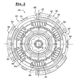
- the guide washers 26, 28 are secured to rotate from one another by their outer peripheral edges 34, 36, which comprise adjacent angular sectors 38 distributed regularly around the axis XX, as can be seen on the figure 2 .
- the adjacent angular sectors 38 are joined by their radial faces vis-à-vis, here by means of rivets 40.
- the contiguous angular sectors 38 circumferentially delimit between them guide and abutment notches 42, which are each provided to allow the angular displacement of an associated radial tab 44, formed in the radial extension of the outer peripheral edge 46 of a web 29 forming the output element of the damper 20.
- Each notch 42 has two circumferentially opposed radial edges 48, 50 which form abutment surfaces for the associated radial tab 44.
- the abutment of the radial lugs 44 against the abutment surfaces 48, 50 therefore determines a relative angular position of abutment between the guide washers 26, 28 and the veil 29.
- the torque transmitted by the turbine wheel 12 to the turbine hub 18 is transmitted to the guide washers 26, 28, forming the input element of the damper 20, then to the sail 29, forming the output element. of the damper 20, by means of elastic members with circumferential action 50, after an angular displacement of the guide washers 26, 28 to their angular position of abutment with the web 29.
- the elastic members 50 with circumferential action are interposed between the guide washers 26, 28 and the web 29. To do this, the web 29 has windows 52 in which the elastic members 50 are mounted.
- the guide washers 26, 28 also each comprise a central guide portion 54, 56 which is provided with windows 58, 60 arranged in line with the windows 52 of the web 29.
- the elastic members 50 are respectively bearing on the radial edges 62, 64 of the windows 58, 60 of the guide washers 26, 28 and on the radial edges 66, 68 of the windows 52 of the web 29.
- the elastic members 50 are held axially by the circumferentially oriented edges of the windows 58, 60 of the guide washers 26, 28.
- the elastic members 50 are thus circumferentially biased between the input elements 26, 28 and output 29 of the damper 20, to the extent of a relative angular displacement determined by the circumferential displacement of the radial tabs 44 of the sail 29 in the notches 42 of the guide washers 26, 28, to an angular position of abutment.
- the web 29 is integral in rotation, meshing without play, with an outlet hub 70 which is rotatably connected, here via splines 72, with the driven shaft A2.
- the web 29, forming the output element of the damper 20 can be made in one piece with the outlet hub 70.
- the apparatus 10 comprises, in the front, a sealed chamber 74, which is delimited axially by the front shell 2 of the housing and by a piston 76.
- the piston 76 is axially movable so as to be able to clamp axially under the housing. action of the pressure of the oil in the chamber 74, the clutch 16, here multi-disk type.
- such a clutch 16 comprises a plurality of flanges 78 and friction discs 80, interposed axially between two successive flanges 78, each friction disc 80 being provided on its front and rear faces of friction linings.
- the flanges 78 comprise, at their outer radial periphery, a toothing or any other means adapted to rotate the shapes of the flanges 78 to a first connecting piece 82 by rotationally co-operating.
- the first connecting piece 82 is integral in rotation with the shell 2 on which it is for example reported by welding.
- the discs 80 comprise, in a similar manner to the flanges 78, meshing means, at their inner radial periphery, which provide the connection in rotation with a second connecting piece 84, which is integral in rotation with the inlet of the damper 20, for example of the front guide washer 28.
- the second connecting piece 84 here comprises a radial portion 86, at its rear axial end, which is fixed on the front face of the front guide washer 28 by means of rivets 88.
- the second connecting piece 84 may be fixed to the front guide washer 28 by other means, including friction welding.
- the piston 76 comprises, at its outer radial periphery, an annular groove in which are mounted first dynamic sealing means, such as a segment 90, which cooperates with an axial surface vis-à-vis the first piece of connection 82 and, at its inner radial periphery, a clean surface to cooperate with second dynamic sealing means, such as a segment 92, which is mounted in an annular groove of a hub, or centralizer 94, which surrounds the piston 76, with which it is connected in rotation by meshing.
- first dynamic sealing means such as a segment 90
- second dynamic sealing means such as a segment 92, which is mounted in an annular groove of a hub, or centralizer 94, which surrounds the piston 76, with which it is connected in rotation by meshing.
- the dynamic sealing means 90, 92 thus delimit the chamber 74, which is supplied with oil by a hollow shaft, here the driven shaft A2, adapted radial passages 96 being provided in the centralizer 94.
- the apparatus 10 is here of the "three-way" type, that is to say that it comprises a first channel V1 for supplying the hydraulic circuit of the converter 14 and a second channel V2 for output, and a third channel supply V3 of the chamber 74 to move the piston 76 axially, this third channel V3 being independent of the first V1 and second V2 channels of the converter 14.
- a first phase of operation in a first phase of operation, called “converter phase", the torque of the driving shaft A1 is transmitted to the impeller wheel 11 which drives, by circulation of oil between the blades 11a and 12a, the turbine wheel 12 .
- the damper 20 is practically not involved in the damping of vibrations or torsional oscillations resulting in particular from motor acyclisms. Indeed, the vibrations or torsional oscillations are filtered mainly in the oil by the converter 14, since the transmission of the engine torque is achieved by means of the kinetic energy of the oil in the converter 14, the damper 20 merely transmitting the torque of the turbine wheel 12 to the output hub 70.
- the sealed chamber 74 of the casing 1, 2 is fed in such a way that the piston 76 exerts an axial pressure towards the rear, against the clutch 16, under the action of the pressure of the oil in the chamber 74, to couple the A1 and A2 drive shafts.
- the clutch 16 is generally activated after the vehicle has been started and after the hydraulic coupling of the drive shafts A1 and A2, in order to avoid the loss of efficiency induced in particular by phenomena of slippage between the turbine wheels 12 and the impeller 11.
- the resilient members 50 dampen the torsional oscillations and, after angular displacement of the clearance connection between the guide washers 26, 28 and the web 29 of the damper 20, the torque is transmitted to the web 29, which is rotatably connected. to the driven shaft A2, through the hub 70.
- the apparatus 10 comprises means for restricting the circulation of the oil in a generally radial direction, at least within the axial space before E1, which is located between the front washer 28 and the sail 29, so as to promote the circulation of the oil, the supply path V1 to the escape route V2, through the locking clutch 16.
- the locking clutch 16 comprises for this purpose radial bores 98, which are formed in the first 82 and in the second 84 connecting pieces, so as to allow the radial circulation of the oil through the clutch 16, between the flanges 78 and the friction discs 80.
- the circulation of the oil through the clutch 16 makes it possible to cool the clutch 16, in particular when the clutch 16 is engaged, or semi-engaged, and that a slip occurs between the flanges 78 and the friction discs 80, producing a heating.
- the damper 20 comprises an axial elastic spring washer 100 which is interposed axially between the front guide washer 28 and the web 29.
- This elastic washer 100 is here a frustoconical washer which is substantially axially continuous, circumferentially, on each face facing each other, respectively of the front guide washer 28 and the web 29.
- the front elastic washer 100 is disposed radially inward with respect to the resilient members 50.
- the elastic washer before 100 thus forms a substantially sealed barrier, which prevents the circulation of the oil radially inwards, in the axial space before E1.
- the front guide washer 28 extends radially inwards, generally to the outlet hub 70.
- the axial bores 102, 104, 106 of each series are for example angularly distributed regularly.
- the axial bores 102 of the front guide washer 28 are arranged radially inward with respect to the front elastic washer 100.
- the turbine hub 18 here comprises grooves which extend radially in its front face and which allow the "connection" between the axial bores 104 of the web 29 and the axial bores 106, the latter being offset radially inwards, by relation to axial bores 104.
- the axial passages 106 may be made in the form of axial grooves, which are formed in the inner periphery of the turbine hub 18. These axial grooves are for example angularly distributed regularly.
- Such grooves can be made easily by machining, which reduces the manufacturing costs of the turbine hub 18.
- the front guide washer 28 comprises a rearward convex annular boss 108, which can be made by stamping, and which allows the centering of the elastic washer before 100.
- centering boss 108 may be interrupted circumferentially, so as to form angularly distributed centering sectors.
- the damping device 20 comprises a rear spring washer 110, of the same type as the front elastic washer 100, which is interposed axially in the rear axial space E2, between the sail 29 and the rear guide washer 26.
- the rear spring washer 110 is here arranged radially between the resilient members 50 and the teeth 32 of the rear guide washer 26.
- the rear spring washer 110 is here centered on the sail 29 by means of an axial recess 112 formed in the sail 29.
- the rear spring washer 110 forms a barrier against the flow of oil, which comes from the feed path V1, and which circulates between the damper 20 and the wheel turbine 12.
- the circulation of the oil in the apparatus 10 is illustrated on the figure 1 , by arrows.
- the spring washers 100, 110 contribute to the damping of the torsional oscillations in the apparatus 10, since they form friction elements between the guide washers 26, 28 and the web 29.
- the spring washers 100, 110 participate in the axial positioning of the elements of the damper 20 in the apparatus 10, compensating axial clearances.
- the seal is maintained, even in case of axial displacement of the web 29 relative to the guide washers 26, 28.
- the spring washers 100, 110 may be treated, for example by carbonitriding.
- edges of the spring washers 100, 110, which are in contact with the guide washer 26, 28 associated or with the web 29, are rounded, so as to avoid deterioration of the surfaces in contact.
- an oil flow can circulate in the rear axial space E2, passing between the teeth 30 of the turbine hub 18 and the teeth 32 of the rear guide washer 26.
- oil flow is low, since the rear guide washer 26 meshes without play on the turbine hub 18, and because the oil flow depends only on the radial clearance between the teeth 30, 32.
- the axial displacement of the rear guide washer 26, relative to the turbine hub 18, does not modify the passage section of the oil between the two elements 18, 26, unlike an apparatus 10 in which the teeth of the turbine hub 18 form pavers, which extend axially forwardly from the front radial surface of the turbine hub 18, such as the apparatuses shown in the documents FR-A-2765939 and US Patent 5,975,261 .
- This arrangement also makes it possible to reduce the production costs, in particular because it is easier to perform by machining radial teeth 30, 32, at the outer and inner periphery, respectively of the turbine hub 18 and the rear guide washer. 26, than to make teeth that extend axially forward, as in the documents cited above.
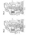
- a second embodiment which is represented on the figure 3 , provides for axially interposing the rear spring washer 110 between the web 29 and a radial front surface 114 of the turbine hub 18.
- the front face of the turbine hub 18 here comprises a countersink in which the rear spring washer 110 is centered by its inner radial periphery.
- the front face of the turbine hub 18, on which bears the rear spring washer 110 is treated for example by carbo-nitriding, so as to increase its hardness.
- This treatment can be performed, for example, at the same time as the treatment of the teeth 30.
- damper 20 comprises a single spring washer 100, in the axial space before E1, and wherein the turbine hub 18 has a continuous annular radial surface 116, which is provided to be in axial support forwards against the rear face of the veil 29.
- annular radial surface 116 of the turbine hub 18 being in continuous axial abutment against the web 29, this prevents the radial circulation of the oil inwards, in the rear axial space E2.
- the embodiment shown here is provided with an alternative embodiment of the centering means of the elastic washer before 100.
- the front guide washer 28 comprises several "keystrokes", which form on the rear face of the washer 28 centering reliefs 118, which are angularly distributed, preferably in a regular manner.
- the centering reliefs 118 are for example intercalated circumferentially between two rivets 88 for fixing the second connecting piece 84.
- the central guide portion 54, 56 of each guide ring 26, 28 is full, ie it has no window 58, 60.
- central guide portion 54, 56 of each guide ring 26, 28 thus forms, in line with the elastic members 50; complementary bosses 120 instead of windows 58, 60.
- the bosses 120 delimit, at each of their circumferential ends, a bearing surface 122, 124 for the elastic members 50, which generally has the same function as the radial edges 62, 64 of the windows 58, 60.
- the elastic members 50 comprise, in each window 52 of the web 29, a pair of coaxial coil springs 126, 128.
- the guide washers 26, 28 must therefore comprise, for each pair of springs 126, 128, two bearing surfaces, circumferentially opposed, on which the two springs 126, 128 can bear.
- each pair of springs 126, 128, two cups 130, 132 which abut against the bearing surfaces 122, 124 of the bosses 120, and which themselves form bearing surfaces for the springs 126, 128.
- the outer peripheral edge 34, 36 of each guide washer 26, 28 is continuous and adjacent to the outer peripheral edge 34, 36 vis-à-vis, so as to "close” the damper 20 at its outer periphery.
- each guide ring 26, 28 has angular sectors 38 which are riveted to the angular sectors 38 facing each other.
- the front guide washer 28 comprises angular sectors 134, which are interposed between two riveted angular sectors 38, and which each form a boss 136, convex towards the front, delimiting an axial space, between the two guide washers 26, 28, to allow the angular clearance of the radial tab 44 associated with the sail 29.
- the bosses 136 replace the circumferential notches 42.
- Each boss 136 is bounded radially outwards by a circumferential edge 138, which bears axially against the front face of the outer peripheral edge 34 opposite the rear guide washer 26.
- the outer peripheral edge 34 of the rear guide washer 26 is here substantially flat over its entire circumference, that is to say that the angular sectors 134 interposed between two riveted angular sectors 38 have no boss, vis-à-vis bosses 136 of the front guide washer 28.
- the realization of the guide washers 26, 28 is facilitated.
- the bosses 136 are only made in the front washer 28, so that, in view of manufacturing tolerances, in particular stamping, it is easier to ensure a substantially continuous contact between the edges.
- bosses 136 can be made both in the front washer 28 and in the rear guide washer 26, so that the outer peripheral edges 34, 36 of the two washers 26 , 28 are substantially symmetrical with respect to a plane of symmetry transverse to the axis XX.
- the guide washers 26, 28 are closed, in line with the elastic members 50, as in the fourth embodiment, but the peripheral edges 34, 36 of the guide washers 26, 28 are made as in the first embodiment, that is to say they have notches 42 "open".
- front and rear spring washers 100, 110 of the same type as those of the first embodiment, which are interposed axially between the web 29 and the associated guide washer 26, 28, and which are arranged radially on the outside, with respect to the resilient members 50.
- FIG. 8 there is shown a fifth embodiment of the invention, which is similar to the previous one, but in which the rear guide washer 26 is similar to that of the third embodiment, which is shown in FIG. figure 4 .
- the rear guide washer 26 is therefore not full, but it includes windows 58 to the right of the elastic members 50.
- the outer peripheral edge 34 of the rear guide washer 26 extends axially rearwardly by a deflector 140 in the form of an axial skirt.
- Deflector 140 deflects the flow of oil to clutch 16.
- the deflector 140 is arranged to minimize the axial space between the outer periphery of the damper 20 and the turbine wheel 12, so that the majority of the oil flow flows towards the axial space between the front shell 2 and the outer periphery of the damper 20, to pass through the clutch 16.
- the deflector 140 may also equip an apparatus 10 in which the two guide washers 26, 28 are solid, such as that which is shown in FIGS. Figures 5 to 7 .
- the outlet hub 70 comprises, at the front, axial abutment means cooperating with a portion of the front face of the veil 29. and with a portion of the rear face of the front guide washer 28, so as to axially retain the damping device 20 on the output hub 70.
- These axial abutment means allow, during the operation of the apparatus 10, to limit the axial displacement of the web 29, relative to the output hub 70, forwards.
- axial abutment means also make it possible to assemble the damping device 20 on the outlet hub 70, before being mounted in the hydrokinetic coupling apparatus 10, so as to produce a subassembly which facilitates the transport of these elements 20, 70 to their place of installation in the hydrokinetic coupling apparatus 10.
- the outlet hub 70 has an abutment ring 142, or rod, which is mounted on the axial face 144 of its main section 146.
- Main section 146 is here referred to as the section of outlet hub 70 in which meshing teeth 148 are formed with teeth 150 of web 29.
- the abutment ring 142 here of circular axial section, is received in a peripheral groove 152 of the main section 146, arranged in the vicinity of the axial front end of the main section 146.
- the sail 29 When the sail 29 is mounted on the outlet hub 70, the sail 29 is retained axially forwardly, since it comprises, at its inner periphery, a radial surface portion 154 facing the ring axially. stop 142.
- the web 29 is also retained axially rearwardly. Indeed, the web 29 is "trapped" between the two guide washers 26, 28, and the front guide washer 28 has, at its inner periphery, a radial surface portion 156 vis-à-vis axially of the ring. abutment 142, and here vis-à-vis axially the outer peripheral edge of the radial surface before 158 of the main section 146. The radial surface portion 156 is therefore likely to abut axially rearwardly against the radial surface before 158 of the main section 146.
- the diameter of the inner periphery of the front guide washer 28 is smaller than the outside diameter of the main section 146 of the outlet hub 70, so that the radial surface portion 156 is arranged facing axially from the radial surface before 158 of the main section 146.
- a second embodiment of the axial stop means is represented on the figure 9 . -
- the stop ring 142 is replaced by a radial peripheral extension, or rim 160, at the axial front end of the main section 146 of the outlet hub 70.
- the flange 160 is formed on the main section 146, before the teeth 148.
- the teeth 148 are then produced over the entire axial thickness of the main section 146, so that the flange 160 then has a profile, in cross section, shaped teeth.
- each tooth 148 of the main section 146 then has, at its forward axial end, a small outer edge 160.
- the diameter of the inner periphery of the front guide washer 28 is such that the front guide washer 28 has a radial surface portion 156 facing axially, at least of the radial surface before the rim 160.
- the main section 146 of the output hub 70 has a flange 160 similar to that of the second embodiment.
- the apparatus 10 generally comprises bearing means 162 which are interposed axially between the centralizer 94 and the radial front surface 158 of the main section 146.
- These rolling means 162 here consist of a needle stop comprising elements mounted between two radial flanges before 164 and rear 166.
- the rear radial flange 166 is for example crimped on the output hub 70.
- the rear radial flange 166 has an outer radial extension 168, which is adjacent to the front radial surface 158 of the main section 146, and which extends outwardly beyond the flange 160.
- This third embodiment makes it possible in particular to increase the diameter of the opening formed by the inner periphery of the front guide washer 28, since the radial extension 168 forms an axial abutment surface, opposite the radial surface portion 156, which extends farther outward than the flange 160.
- the main section 146 of the output hub 70 has a stop ring 142 similar to that of the figure 8 , and a rear radial flange 166 similar to that of the figure 10 .
Abstract
Description
La présente invention concerne un appareil d'accouplement hydrocinétique, notamment pour un véhicule automobile. Un appareil selon le préambule de la revendication indépendante / est connu du document
On connaît déjà dans l'état de la technique, par exemple des documents
- un carter formé d'une première coquille qui lie en rotation un arbre menant et une roue d'impulseur ;
- une roue de turbine solidaire en rotation, par une liaison sans jeu, d'un moyeu de turbine qui est propre à être lié en rotation à un arbre mené ;
- un embrayage de verrouillage du couplage des arbres menant et mené comportant un piston, mobile axialement pour lier, de manière débrayable, une deuxième coquille du carter à l'arbre mené, en serrant au moins un disque de friction solidaire en rotation, d'une part, de la deuxième coquille de carter par l'intermédiaire d'une première pièce de liaison et, d'autre part, de l'élément d'entrée d'un dispositif d'amortissement par l'intermédiaire d'une deuxième pièce de liaison ;
- a casing formed of a first shell which rotates a driving shaft and an impeller wheel;
- a turbine wheel integral in rotation, by a link without play, a turbine hub which is adapted to be rotatably connected to a driven shaft;
- a clutch coupling of the coupling of the driving and driven shafts comprising a piston, movable axially to disengageably bind a second shell of the casing to the driven shaft, by tightening at least one rotationally integral friction disk, a of the second housing shell via a first connecting piece and, secondly, of the input element of a damping device via a second housing part. binding;
Ces appareils d'accouplement hydrocinétique sont du type à « trois voies », c'est à dire que le circuit hydraulique de chaque appareil comprend une première voie pour l'alimentation en fluide du convertisseur, une seconde voie d'évacuation, et une troisième voie, indépendante des première et seconde voies du convertisseur, qui permet d'alimenter la chambre de commande du piston de l'embrayage de verrouillage, en vue de déplacer axialement le piston.These hydrokinetic coupling devices are of the "three-way" type, that is to say that the hydraulic circuit of each apparatus comprises a first channel for supplying fluid to the converter, a second escape route, and a third channel, independent of the first and second channels of the converter, which supplies the control chamber of the piston of the clutch. locking device, in order to axially move the piston.
Généralement, la voie d'alimentation amène le fluide dans le convertisseur, entre la roue d'impulseur et la roue de turbine, puis le fluide est évacué du convertisseur par l'extérieur, en passant dans l'espace radial entre la roue de turbine et la deuxième coquille du carter.Generally, the supply path brings the fluid into the converter, between the impeller wheel and the turbine wheel, and the fluid is removed from the converter from the outside, passing in the radial space between the turbine wheel and the second shell of the housing.
Le fluide circule ensuite radialement vers l'intérieur, dans l'espace axial entre la turbine et la deuxième coquille, pour être évacué par la voie d'évacuation, qui est par exemple agencée entre l'arbre mené et un manchon de réaction portant une roue de réaction centrale.The fluid then circulates radially inwards, in the axial space between the turbine and the second shell, to be evacuated by the escape route, which is for example arranged between the driven shaft and a reaction sleeve carrying a central reaction wheel.
En se dirigeant vers la voie d'évacuation, le fluide traverse radialement l'embrayage de verrouillage, qui comporte des ouvertures radiales à cet effet, et il circule radialement et axialement à l'intérieur du dispositif d'amortissement.As it moves towards the evacuation route, the fluid passes radially through the locking clutch, which has radial openings for this purpose, and it circulates radially and axially inside the damping device.
Lorsque l'embrayage est verrouillé et lorsqu'il est dans une phase de glissement, c'est à dire lorsque le piston est commandé dans le sens de son engagement contre les disques de friction, il est nécessaire, pour le refroidissement de l'embrayage, que la plus grande quantité possible du fluide traverse l'embrayage.When the clutch is locked and when it is in a sliding phase, ie when the piston is controlled in the direction of its engagement against the friction discs, it is necessary for the cooling of the clutch that as much fluid as possible passes through the clutch.
Cependant, on a constaté qu'une quantité importante du fluide passe dans l'espace axial entre l'embrayage et la roue de turbine, en traversant le dispositif d'amortissement, sans traverser l'embrayage, ce qui est pénalisant pour le refroidissement de l'embrayage.However, it has been found that a large quantity of the fluid passes into the axial space between the clutch and the turbine wheel, passing through the damping device, without passing through the clutch, which is disadvantageous for the cooling of the clutch. the clutch.
Ce phénomène est d'autant plus présent que, pendant le fonctionnement de l'appareil d'accouplement, sous la pression du fluide, le carter se déforme en « gonflant », ce qui augmente la taille de l'espace axial entre l'embrayage et la roue de turbine.This phenomenon is all the more present that, during the operation of the coupling apparatus, under the pressure of the fluid, the housing is deformed by "swelling", which increases the size of the axial space between the clutch and the turbine wheel.
L'invention vise notamment à remédier à cet inconvénient, en proposant une solution simple et économique.The invention aims in particular to remedy this drawback by proposing a simple and economical solution.
Dans ce but, l'invention propose un appareil d'accouplement hydrocinétique, notamment pour un véhicule automobile, du type comportant :
- un carter formé d'une première coquille qui lie en rotation un arbre menant et une roue d'impulseur ;
- une roue de turbine solidaire en rotation, par une liaison sans jeu, d'un moyeu de turbine qui est propre à être lié en rotation à un arbre mené ;
- un embrayage de verrouillage du couplage des arbres menant et mené comportant un piston, mobile axialement pour lier, de manière débrayable, une deuxième coquille du carter à l'arbre mené, en serrant au moins un disque de friction solidaire en rotation, d'une part, de la deuxième coquille de carter par l'intermédiaire d'une première pièce de liaison et, d'autre part, de l'élément d'entrée d'un dispositif d'amortissement par l'intermédiaire d'une deuxième pièce de liaison ;
le dispositif d'amortissement comportant des moyens pour restreindre la circulation du fluide dans une direction globalement radiale, au moins à l'intérieur de l'espace axial avant, qui est situé entre la rondelle' avant de guidage et le voile, de manière à favoriser la circulation du fluide, de la voie d'alimentation vers la voie d'évacuation, à travers l'embrayage de verrouillage, dans lequel lesdits
moyens pour restreindre la circulation du fluide comportent au moins une rondelle élastique avant à effet axial qui est interposée axialement entre le voile et la rondelle avant de guidage, de manière à former une barrière à l'encontre de la circulation radiale du fluide à l'intérieur de l'espace axial avant du dispositif d'amortissement, et/ou
au moins une rondelle élastique arrière à effet axial qui est interposée axialement entre le voile et une surface radiale en vis-à-vis vers l'arrière, et qui est disposée radialement à l'intérieur, par rapport aux organes élastiques, de manière à former une barrière à l'encontre de la circulation radiale du fluide à l'intérieur de l'espace axial arrière, situé entre le voile et la rondelle arrière de guidage ; Selon d'autres caractéristiques de l'invention:
- chaque rondelle élastique est une rondelle tronconique ;
- la rondelle élastique est centrée par rapport à l'axe au moyen d'un profil complémentaire de centrage qui est réalisé dans la rondelle de guidage associée, ou dans le voile ;
- le profil de centrage comporte plusieurs frappes formant, sur la rondelle de guidage associée ou sur le voile, des reliefs de centrage répartis angulairement ;
- la rondelle arrière de guidage est solidaire à rotation du moyeu de turbine;
- la rondelle arrière de guidage et le moyeu de turbine sont solidaires à rotation par engrènement, au moyen de dents qui sont portées respectivement par la périphérie intérieure de la rondelle arrière de guidage et par la périphérie extérieure du moyeu de turbine ;
- le moyeu de turbine comporte une surface radiale annulaire continue qui vient en appui axial contre la face arrière du voile, de manière à empêcher la circulation radiale du fluide à l'intérieur de l'espace axial arrière ;
- la rondelle élastique arrière est interposée axialement entre le voile et la face avant du moyeu de turbine ;
- la surface du moyeu de turbine susceptible d'être en contact avec la rondelle élastique arrière, et/ou la rondelle élastique, est traitée en vue d'augmenter sa dureté ;
- la partie centrale de la rondelle avant de guidage, et/ou la partie centrale de la rondelle arrière de guidage, qui est située au droit des organes élastiques, est pleine, grâce à quoi le fluide ne peut circuler dans l'espace axial associé en traversant la partie centrale de la rondelle de guidage ;
- le dispositif d'amortissement comporte des paires de coupelles qui sont agencées dans les parties centrales des rondelles de guidage de manière à former des surfaces d'appui pour les organes élastiques à action circonférentielle ;
- chaque rondelle de guidage comporte un bord périphérique extérieur continu, et les deux bords extérieurs sont adjacents, de manière à fermer la périphérie externe du dispositif d'amortissement ;
- le bord périphérique extérieur d'une des rondelles de guidage se prolonge axialement vers l'arrière par un déflecteur qui dévie le flux d'huile vers l'embrayage ;
- le déflecteur forme une jupe axiale, qui minimise l'espace axial entre la périphérie externe du dispositif d'amortissement et la roue de turbine ;
- le déflecteur est formé par une extension radiale extérieure de la rondelle arrière de guidage en une seule pièce ;
- la rondelle avant de guidage et le voile comportent chacun des perçages axiaux, qui sont agencés globalement axialement en vis-à-vis, en vue de faciliter la circulation du flux d'huile, qui a traversé l'embrayage, vers la voie d'évacuation ;
- le moyeu de turbine comporte des passages axiaux, au voisinage dans sa périphérie interne, en vue de faciliter la circulation du flux d'huile, qui a traversé l'embrayage, vers la voie d'évacuation
- les passages axiaux sont réalisés sous la forme de gorges axiales.
- a casing formed of a first shell which rotates a driving shaft and an impeller wheel;
- a turbine wheel integral in rotation, by a link without play, a turbine hub which is adapted to be rotatably connected to a driven shaft;
- a clutch coupling of the coupling of the driving and driven shafts comprising a piston, movable axially to disengageably bind a second shell of the casing to the driven shaft, by tightening at least one rotationally integral friction disk, a of the second housing shell via a first connecting piece and, secondly, of the input element of a damping device via a second housing part. binding;
the damping device comprising means for restricting the flow of fluid in a generally radial direction, at least within the forward axial space, which is located between the front guide washer and the web, so as to to promote the circulation of the fluid, from the feed path to the escape route, through the locking clutch, in which said
means for restricting the circulation of the fluid comprise at least one axial spring front washer which is interposed axially between the web and the front guide washer, so as to form a barrier against the radial flow of the fluid to the inside the axial space before the damping device, and / or
at least one axially acting rear spring washer which is interposed axially between the web and a radial surface facing rearwardly, and which is disposed radially inwardly with respect to the elastic members, so as to forming a barrier against the radial flow of the fluid within the rear axial space, located between the web and the rear guide washer; According to other features of the invention:
- each elastic washer is a frustoconical washer;
- the spring washer is centered with respect to the axis by means of a complementary centering profile which is formed in the associated guide washer, or in the web;
- the centering profile comprises several strokes forming, on the associated guide washer or on the web, angularly distributed centering reliefs;
- the rear guide washer is integral with the rotation of the turbine hub;
- the guide rear washer and the turbine hub are secured to rotation by meshing, by means of teeth which are respectively carried by the inner periphery of the rear guide washer and the outer periphery of the turbine hub;
- the turbine hub comprises a continuous annular radial surface which bears axially against the rear face of the web, so as to prevent the radial circulation of the fluid inside the rear axial space;
- the rear elastic washer is interposed axially between the web and the front face of the turbine hub;
- the surface of the turbine hub capable of being in contact with the rear spring washer, and / or the spring washer, is treated in order to increase its hardness;
- the central portion of the front guide washer, and / or the central portion of the rear guide washer, which is located in line with the elastic members, is solid, whereby the fluid can not circulate in the axial space associated with passing through the central portion of the guide ring;
- the damping device comprises pairs of cups which are arranged in the central portions of the guide washers so as to form bearing surfaces for the circumferentially acting elastic members;
- each guide ring has a continuous outer peripheral edge, and the two outer edges are adjacent, so as to close the outer periphery of the damping device;
- the outer peripheral edge of one of the guide washers extends axially rearwardly by a deflector which deflects the flow of oil to the clutch;
- the deflector forms an axial skirt, which minimizes the axial space between the outer periphery of the damping device and the turbine wheel;
- the deflector is formed by an outer radial extension of the rear guide washer in one piece;
- the front guide washer and the sail each comprise axial bores, which are arranged generally axially vis-à-vis, in order to facilitate the circulation of the oil flow, which has passed through the clutch, to the track of evacuation;
- the turbine hub has axial passages, in the vicinity in its inner periphery, to facilitate the circulation of the oil flow, which has passed through the clutch, towards the evacuation route
- the axial passages are in the form of axial grooves.
D'autres caractéristiques et avantages de l'invention apparaîtront à la lecture de la description détaillée qui suit pour la compréhension de laquelle on se reportera aux dessins annexés parmi lesquels:
- la
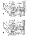
figure 1 est une demi-vue en coupe axiale qui représente un appareil d'accouplement hydrocinétique selon un premier mode de réalisation de l'invention qui comprend deux rondelles élastiques d'étanchéité et dans lequel la rondelle élastique arrière est interposée entre le voile et la rondelle de guidage arrière de l'amortisseur ; - la
figure 2 est vue de face qui représente l'amortisseur de lafigure 1 ; - la
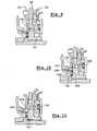
figure 3 est une vue similaire à celle de lafigure 1 qui représente un deuxième mode de réalisation de l'invention dans lequel la rondelle élastique arrière est interposée entre le voile et le moyeu de turbine du convertisseur ; - la
figure 4 est une vue similaire à celle de lafigure 1 qui représente un troisième mode de réalisation de l'invention comportant une seule rondelle élastique d'étanchéité ; - la
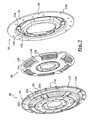
figure 5 est une vue similaire à celle de lafigure 1 qui représente un quatrième mode de réalisation de l'invention dans lequel les rondelles de guidage sont pleines ; - la
figure 6 est une vue arrière qui représente l'amortisseur de lafigure 5 sans sa rondelle arrière de guidage ; - - la
figure 7 est une vue en perspective éclatée qui représente l'amortisseur de lafigure 5 ; - la
figure 8 est une vue similaire à celle de lafigure 1 qui représente un cinquième mode de réalisation de l'invention dans lequel l'amortisseur est équipé d'un déflecteur ; - la
figure 9 est une vue similaire à celle de lafigure 1 qui représente un mode de réalisation des moyens de butée axiale en forme de rebord porté par le moyeu de sortie de l'appareil d'accouplement ; - la
figure 10 est une vue similaire à celle de lafigure 1 qui représente un mode de réalisation des moyens de butée axiale utilisant le flasque radial arrière d'une butée à aiguille ; - la
figure 11 est une vue similaire à celle de lafigure 1 qui représente un mode de réalisation des moyens de butée axiale utilisant une bague et un flasque radial.
- the
figure 1 is a half-view in axial section which shows a hydrokinetic coupling apparatus according to a first embodiment of the invention which comprises two resilient sealing washers and wherein the rear spring washer is interposed between the sail and the washer of rear guide of the shock absorber; - the
figure 2 is front view which represents the damper of thefigure 1 ; - the
figure 3 is a view similar to that of thefigure 1 which represents a second embodiment of the invention in which the rear elastic washer is interposed between the web and the turbine hub of the converter; - the
figure 4 is a view similar to that of thefigure 1 which represents a third embodiment of the invention comprising a single elastic sealing washer; - the
figure 5 is a view similar to that of thefigure 1 which represents a fourth embodiment of the invention wherein the guide washers are solid; - the
figure 6 is a rear view that represents the damper of thefigure 5 without its rear guide washer; - - the
figure 7 is an exploded perspective view that represents the damper of thefigure 5 ; - the
figure 8 is a view similar to that of thefigure 1 which represents a fifth embodiment of the invention in which the damper is equipped with a deflector; - the
figure 9 is a view similar to that of thefigure 1 which represents an embodiment of the flange-shaped axial abutment means carried by the output hub of the coupling apparatus; - the
figure 10 is a view similar to that of thefigure 1 which represents an embodiment of the axial abutment means using the radial rear flange of a needle stop; - the
figure 11 is a view similar to that of thefigure 1 which represents an embodiment of the axial abutment means using a ring and a radial flange.
Dans la description qui suit, des composants identiques, similaires, ou analogues seront désignés par les mêmes chiffres de référence.In the following description, identical, similar, or like components will be designated by the same reference numerals.
Afin de faciliter la compréhension de la description et des revendications, on utilisera, à titre non limitatif, des orientations « avant » et « arrière » correspondant respectivement à la gauche et à la droite de la
Comme cela est connu de l'état de la technique, un appareil d'accouplement hydrocinétique 10 tel qu'illustré à la
Les coquilles 1, 2 sont de préférence assemblées par soudage.The
Le convertisseur de couple 14 comporte une roue d'impulseur arrière 11, une roue de turbine avant 12 et une roue de réaction centrale 13.The
La roue d'impulseur 11 comporte des aubes 11 a qui sont portées par la coquille arrière 1 qui est solidaire, de manière étanche de la coquille avant 2 d'entraînement. La coquille 1 est propre à être liée en rotation à un arbre menant A1.The
La roue de turbine 12 comporte aussi des aubes 12a qui font face aux aubes 11 a de la roue d'impulseur 11, et la roue de turbine 12 est liée en rotation à un moyeu de turbine 18 qui est apte à être lié en rotation à un arbre mené A2, coaxial à l'axe X-X de l'appareil 10, par l'intermédiaire ici d'un dispositif d'amortissement 20.The
Dans le cas d'une application à un véhicule automobile, l'arbre menant A1 est constitué par le vilebrequin du moteur à combustion interne du véhicule, tandis que l'arbre mené A2 est constitué par l'arbre d'entrée de la transmission du véhicule, relié à des moyens de changement de rapport de vitesse.In the case of an application to a motor vehicle, the driving shaft A1 is constituted by the crankshaft of the internal combustion engine of the vehicle, while the driven shaft A2 is constituted by the input shaft of the transmission of the vehicle. vehicle connected to gearshift means.
La roue de turbine 12 est ici solidaire en rotation, par une liaison sans jeu, du moyeu de turbine 18. La liaison entre la roue de turbine 12 et le moyeu de turbine 18 est ici réalisée par soudage à friction, entre une surface radiale avant 22 de la périphérie interne de la roue de turbine 12 et une surface radiale arrière 24 du moyeu de turbine 18, axialement en vis-à-vis.The
Bien entendu, la liaison entre la roue de turbine 12 et le moyeu de turbine 18 peut être réalisée aussi par d'autres moyens, par exemple par rivetage ou par sertissage.Of course, the connection between the
Le moyeu de turbine 18 est prévu pour être lié en rotation à l'arbre mené A2 par l'intermédiaire du dispositif d'amortissement 20, ou amortisseur, qui comprend un élément d'entrée 26, 28 et un élément de sortie 29.The
L'élément d'entrée de l'amortisseur 20 est ici constitué par des rondelles de guidage 26, 28 dont l'une, dite rondelle arrière de guidage 26, est liée en rotation sans jeu par engrènement avec le moyeu de turbine 18.The input element of the
A cet effet, le bord périphérique externe du moyeu de turbine 18 comporte des dents 30 qui s'étendent radialement vers l'extérieur, et qui sont prévues pour coopérer avec des dents 32 complémentaires portées par le bord périphérique interne de la rondelle arrière de guidage 26.For this purpose, the outer peripheral edge of the
On note que l'épaisseur axiale des dents 30 du moyeu de turbine 18 est plus importante que l'épaisseur axiale des dents 32 de la rondelle arrière de guidage 26, de sorte que la rondelle arrière de guidage 26 dispose d'une liberté axiale pour se déplacer vers l'avant ou vers l'arrière, tout en gardant un contact par engrènement entre ses dents 32 et les dents 30 du moyeu de turbine 18.Note that the axial thickness of the
Les rondelles de guidage 26, 28 sont solidaires à rotation l'une de l'autre par leurs bords périphériques extérieurs 34, 36, qui comportent des secteurs angulaires 38 adjacents, répartis régulièrement autour de l'axe X-X, comme on peut le voir sur la
Les secteurs angulaires adjacents 38 sont accolés par leurs faces radiales en vis-à-vis, ici au moyen de rivets 40.The adjacent
Les secteurs angulaires accolés 38 délimitent circonférentiellement entre eux des encoches 42 de guidage et de butée, qui sont prévues chacune pour permettre le débattement angulaire d'une patte radiale 44 associée, formée dans le prolongement radial du bord périphérique extérieur 46 d'un voile 29 formant l'élément de sortie de l'amortisseur 20.The contiguous
Chaque encoche 42 comporte deux bords radiaux 48, 50 opposés circonférentiellement, qui forment des surfaces de butée pour la patte radiale 44 associée.Each
La venue en butée des pattes radiales 44 contre les surfaces de butée 48, 50 détermine donc une position angulaire relative de butée entre les rondelles de guidage 26, 28 et le voile 29.The abutment of the radial lugs 44 against the abutment surfaces 48, 50 therefore determines a relative angular position of abutment between the
Ainsi, le couple transmis par la roue de turbine 12 au moyeu de turbine 18 est transmis aux rondelles de guidage 26, 28, formant l'élément d'entrée de l'amortisseur 20, puis au voile 29, formant l'élément de sortie de l'amortisseur 20, par l'intermédiaire d'organes élastiques à action circonférentielle 50, après un débattement angulaire des rondelles de guidage 26, 28 jusqu'à leur position angulaire de butée avec le voile 29.Thus, the torque transmitted by the
Les organes élastiques 50 à action circonférentielle sont interposés entre les rondelles de guidage 26, 28 et le voile 29. Pour ce faire, le voile 29 comporte des fenêtres 52 dans lesquelles sont montés les organes élastiques 50.The
Les rondelles de guidage 26, 28 comprennent aussi chacune une partie centrale de guidage 54, 56 qui est munie de fenêtres 58, 60 agencées au droit des fenêtres 52 du voile 29.The guide washers 26, 28 also each comprise a
Les organes élastiques 50 sont en appui respectivement sur les bords radiaux 62, 64 des fenêtres 58, 60 des rondelles de guidage 26, 28 et sur les bords radiaux 66, 68 des fenêtres 52 du voile 29. Les organes élastiques 50 sont maintenus axialement par les bords d'orientation circonférentielle des fenêtres 58, 60 des rondelles de guidage 26, 28.The
Les organes élastiques 50 sont ainsi sollicités circonférentiellement entre les éléments d'entrée 26, 28 et de sortie 29 de l'amortisseur 20, dans la mesure d'un débattement angulaire relatif déterminé par le déplacement circonférentiel des pattes radiales 44 du voile 29 dans les encoches 42 des rondelles de guidage 26, 28, jusqu'à une position angulaire de butée.The
Le voile 29 est solidaire en rotation, par engrènement sans jeu, avec un moyeu de sortie 70 qui est lié en rotation, ici par l'intermédiaire de cannelures 72, avec l'arbre mené A2.The
Bien entendu, selon une variante de réalisation (non représentée), le voile 29, formant l'élément de sortie de l'amortisseur 20, peut être réalisé en une seule pièce avec le moyeu de sortie 70.Of course, according to an alternative embodiment (not shown), the
L'appareil 10 comporte, à-l'avant, une chambre étanche 74, qui est délimitée axialement par la coquille avant 2 du carter et par un piston 76. Le piston 76 est mobile axialement de manière à pouvoir venir serrer axialement, sous l'action de la pression de l'huile dans la chambre 74, l'embrayage 16, ici de type multi-disques.The
Comme on l'a représenté sur la
Les flasques 78 comportent, à leur périphérie radiale extérieure, une denture ou tout autre moyen propre à lier en rotation par coopération de formes les flasques 78 à une première pièce de liaison 82. La première pièce de liaison 82 est solidaire en rotation de la coquille 2 sur laquelle elle est par exemple rapportée par soudage.The
Les disques 80 comportent, de manière analogue aux flasques 78, des moyens d'engrènement, à leur périphérie radiale intérieure, qui assurent la liaison en rotation avec une deuxième pièce de liaison 84, qui est solidaire en rotation de l'entrée de l'amortisseur 20, par exemple de la rondelle avant de guidage 28.The
La deuxième pièce de liaison 84 comporte ici une portion radiale 86, à son extrémité axiale arrière, qui est fixée sur la face avant de la rondelle avant de guidage 28 par l'intermédiaire de rivets 88.The second connecting
En variante, la deuxième pièce de liaison 84 peut être fixée sur la rondelle avant de guidage 28 par d'autres moyens, notamment par soudage à friction.Alternatively, the second connecting
Le piston 76 comporte, à sa périphérie radiale extérieure, une gorge annulaire dans laquelle sont montés des premiers moyens d'étanchéité dynamique, tels qu'un segment 90, qui coopère avec une surface axiale en vis-à-vis de la première pièce de liaison 82 et, à sa périphérie radiale intérieure, une surface propre à coopérer avec des seconds moyens d'étanchéité dynamique, tels qu'un segment 92, qui est monté dans une gorge annulaire d'un moyeu, ou centreur 94, qu'entoure le piston 76, avec lequel il est lié en rotation par engrènement.The
Les moyens d'étanchéité dynamique 90, 92 délimitent ainsi la chambre 74, qui est alimentée en huile par un arbre creux, ici l'arbre mené A2, des passages radiaux 96 adaptés étant prévus dans le centreur 94.The dynamic sealing means 90, 92 thus delimit the
On note que l'appareil 10 est ici du type « trois voies », c'est à dire qu'il comprend une première voie V1 d'alimentation du circuit hydraulique du convertisseur 14 et une seconde voie V2 de sortie, et une troisième voie d'alimentation V3 de la chambre 74 pour déplacer axialement le piston 76, cette troisième voie V3 étant indépendante des première V1 et seconde V2 voies du convertisseur 14.It will be noted that the
On expliquera maintenant le fonctionnement classique d'un tel appareil d'accouplement hydrocinétique 10.We will now explain the conventional operation of such a
Dans une première phase de fonctionnement, dite « phase convertisseur », le couple de l'arbre menant A1 est transmis à la roue d'impulseur 11 qui entraîne, par circulation d'huile entre les aubes 11a et 12a, la roue de turbine 12.In a first phase of operation, called "converter phase", the torque of the driving shaft A1 is transmitted to the
Durant la phase convertisseur, l'amortisseur 20 n'intervient pratiquement pas dans l'amortissement des vibrations ou oscillations de torsion issues notamment des acyclismes du moteur. En effet, les vibrations ou oscillations de torsion sont filtrées principalement dans l'huile par le convertisseur 14, puisque la transmission du couple moteur est réalisée par l'intermédiaire de l'énergie cinétique de l'huile dans le convertisseur 14, l'amortisseur 20 se contentant de transmettre le couple de la roue de turbine 12 au moyeu de sortie 70.During the converter phase, the
Dans une seconde phase, dite « phase de couplage », on alimente la chambre étanche 74 du carter 1, 2, de manière que le piston 76 exerce une pression axiale vers l'arrière, contre l'embrayage 16, sous l'action de la pression de l'huile dans la chambre 74, pour coupler les arbres menant A1 et mené A2.In a second phase, called the "coupling phase", the sealed
L'embrayage 16 est généralement activé après le démarrage du véhicule et après le couplage hydraulique des arbres menant A1 et mené A2, pour éviter la perte de rendement induite notamment par des phénomènes de glissement entre les roues de turbine 12 et d'impulseur 11.The clutch 16 is generally activated after the vehicle has been started and after the hydraulic coupling of the drive shafts A1 and A2, in order to avoid the loss of efficiency induced in particular by phenomena of slippage between the
A l'état embrayé, c'est à dire lorsque le piston 76 vient serrer les disques de friction 80 par l'intermédiaire de l'embrayage multi-disques 16, le couple de l'arbre menant A1 est transmis d'abord aux rondelles de guidage 26, 28, puis au voile 29, par l'intermédiaire des organes élastiques 50.In the engaged state, that is to say when the
Les organes élastiques 50 amortissent les oscillations de torsion puis, après débattement angulaire de la liaison à jeu entre les rondelles de guidage 26, 28 et le voile 29 de l'amortisseur 20, le couple est transmis au voile 29, qui est lié à rotation à l'arbre mené A2, par l'intermédiaire du moyeu 70.The
Pour plus de détails quant à la réalisation et au fonctionnement d'un tel appareil d'accouplement hydrocinétique 10, on se reportera à l'un ou l'autre des documents
On décrira maintenant les différentes modes de réalisation de l'invention, en décrivant principalement les différences qui distinguent chaque mode de réalisation par rapport à un autre.The different embodiments of the invention will now be described, mainly describing the differences which distinguish each embodiment with respect to another.
Conformément aux enseignements de l'invention, l'appareil 10 comporte des moyens pour restreindre la circulation de l'huile dans une direction globalement radiale, au moins à l'intérieur de l'espace axial avant E1, qui est situé entre la rondelle avant de guidage 28 et le voile 29, de manière à favoriser la circulation de l'huile, de la voie d'alimentation V1 vers la voie d'évacuation V2, à travers l'embrayage de verrouillage 16.According to the teachings of the invention, the
De manière classique, l'embrayage de verrouillage 16 comporte à cet effet des perçages radiaux 98, qui sont réalisés dans la première 82 et dans la deuxième 84 pièces de liaison, de manière à permettre la circulation radiale de l'huile à travers l'embrayage 16,- entre les flasques 78 et les disques de friction 80.Conventionally, the locking
La circulation de l'huile à travers l'embrayage 16 permet de refroidir l'embrayage 16, en particulier lorsque l'embrayage 16 est engagé, ou semi-engagé, et qu'il se produit un glissement entre les flasques 78 et les disques de friction 80, produisant un échauffement.The circulation of the oil through the clutch 16 makes it possible to cool the clutch 16, in particular when the clutch 16 is engaged, or semi-engaged, and that a slip occurs between the
Conformément à un premier mode de réalisation de l'invention, qui est représenté sur la
Cette rondelle élastique 100 est ici une rondelle tronconique qui est en appui axial sensiblement continu, circonférentiellement, sur chaque face en vis-à-vis, respectivement de la rondelle avant de guidage 28 et du voile 29.This
Avantageusement, la rondelle élastique avant 100 est disposée radialement à l'intérieur, par rapport aux organes élastiques 50.Advantageously, the front
La rondelle élastique avant 100 forme ainsi une barrière sensiblement étanche, qui empêche la circulation de l'huile radialement vers l'intérieur, dans l'espace axial avant E1.The elastic washer before 100 thus forms a substantially sealed barrier, which prevents the circulation of the oil radially inwards, in the axial space before E1.
En effet, le flux d'huile, provenant de la voie d'alimentation V1, qui circule entre la coquille avant 2 et l'amortisseur 20, pénètre dans l'espace axial avant E1 en passant par les fenêtres 60, ou en passant par les encoches 42. Ce flux d'huile se trouve bloqué par la rondelle élastique avant 100, qui l'empêche de se diriger vers la voie d'évacuation V2. Par conséquent, la majorité du flux d'huile va emprunter un chemin plus facile, qui passe par l'embrayage 16.Indeed, the flow of oil from the supply path V1, which flows between the
Le « blocage » de l'huile dans l'espace axial avant E1 provoque donc une augmentation du débit d'huile à travers l'embrayage 16, ce qui améliore le refroidissement de l'embrayage 16.The "blocking" of the oil in the axial space before E1 therefore causes an increase in the oil flow through the clutch 16, which improves the cooling of the clutch 16.
Selon le mode de réalisation représenté ici, la rondelle avant de guidage 28 se prolonge radialement vers l'intérieur, globalement jusqu'au moyeu de sortie 70.According to the embodiment shown here, the
Pour favoriser l'écoulement de l'huile, qui traverse l'embrayage 16, vers la voie d'évacuation V2, on prévoit avantageusement une série de perçages axiaux 102, 104, 106 respectivement dans la rondelle avant de guidage 28, dans le voile 29, et dans le moyeu de turbine 18.To promote the flow of oil, which passes through the clutch 16, to the evacuation route V2, it is expected advantageously a series of
Les perçages axiaux 102, 104, 106 de chaque série sont par exemple répartis angulairement de manière régulière.The axial bores 102, 104, 106 of each series are for example angularly distributed regularly.
Les perçages axiaux 102 de la rondelle avant de guidage 28 sont disposés radialement à l'intérieur, par rapport à la rondelle élastique avant 100.The axial bores 102 of the
Le moyeu de turbine 18 comporte ici des rainures qui s'étendent radialement dans sa face avant et qui permettent le « raccordement » entre les perçages axiaux 104 du voile 29 et les perçages axiaux 106, ces derniers étant déportés radialement vers l'intérieur, par rapport aux perçages axiaux 104.The
Selon une variante de réalisation, qui est représentée sur les
De telles gorges peuvent être réalisées facilement par usinage, ce qui diminue les coûts de fabrication du moyeu de turbine 18.Such grooves can be made easily by machining, which reduces the manufacturing costs of the
Avantageusement, la rondelle avant de guidage 28 comporte un bossage annulaire 108 convexe vers l'arrière, qui peut être réalisé par emboutissage, et qui permet le centrage de la rondelle élastique avant 100.Advantageously, the
Bien entendu, selon une variante de réalisation, le bossage de centrage 108 peut être interrompu circonférentiellement, de manière à former des secteurs de centrage répartis angulairement.Of course, according to an alternative embodiment, the centering
De préférence, selon le premier mode de réalisation, le dispositif d'amortissement 20 comporte une rondelle élastique arrière 110, du même type que la rondelle élastique avant 100, qui est interposée axialement, dans l'espace axial arrière E2, entre le voile 29 et la rondelle arrière de guidage 26.Preferably, according to the first embodiment, the damping
La rondelle élastique arrière 110 est agencée ici radialement entre les organes élastiques 50 et les dents 32 de la rondelle arrière de guidage 26.The
La rondelle élastique arrière 110 est ici centrée sur le voile 29 au moyen d'un décrochement axial 112 formé dans le voile 29.The
De la même manière que la rondelle élastique avant 100, la rondelle élastique arrière 110 forme une barrière à l'encontre du flux d'huile, qui provient de la voie d'alimentation V1, et qui circule entre l'amortisseur 20 et la roue de turbine 12.In the same way as the elastic washer before 100, the
Grâce aux deux rondelles élastiques 100, 110, globalement, le seul chemin possible pour l'huile, entre la voie d'alimentation V1 et la voie d'évacuation V2, passe par l'embrayage 16, ce qui assure la circulation d'une grande quantité d'huile à travers l'embrayage 16, et donc un bon refroidissement de l'embrayage 16.Thanks to the two
La circulation de l'huile dans l'appareil 10 est illustrée, sur la
On note que l'invention s'applique aussi à un appareil 10 dans lequel le sens de circulation de l'huile est inversé par rapport à celui qui est représenté ici.Note that the invention also applies to an
On note que les rondelles élastiques 100, 110 contribuent à l'amortissement des oscillations de torsion dans l'appareil 10, puisqu'elles forment des éléments de frottement entre les rondelles de guidage 26, 28 et le voile 29.It is noted that the
De plus, les rondelles élastiques 100, 110 participent au positionnement axial des éléments de l'amortisseur 20 dans l'appareil 10, en compensant les jeux axiaux.In addition, the
Comme les rondelles 100, 110 sont élastiques, l'étanchéité est maintenue, même en cas de déplacement axial du voile 29 par rapport aux rondelles de guidage 26, 28.As the
Pour améliorer leur dureté, les rondelles élastiques 100, 110 peuvent être traitées, par exemple par carbonitruration.To improve their hardness, the
De préférence, les bords des rondelles élastiques 100, 110, qui sont en contact avec la rondelle de guidage 26, 28 associée ou avec le voile 29, sont arrondis, de manière à éviter une détérioration des surfaces en contact.Preferably, the edges of the
On note que, dans le premier mode de réalisation, un flux d'huile peut circuler dans l'espace axial arrière E2, en passant entre les dents 30 du moyeu de turbine 18 et les dents 32 de la rondelle arrière de guidage 26. Ce flux d'huile est faible, puisque la rondelle arrière de guidage 26 engrène sans jeu sur le moyeu de turbine 18, et parce que le flux d'huile dépend uniquement du jeu radial entre les dents 30, 32. En effet, le déplacement axial de la rondelle arrière de guidage 26, par rapport au moyeu de turbine 18, ne modifie pas la section de passage de l'huile entre les deux éléments 18, 26, contrairement à un appareil 10 dans lequel les dents du moyeu de turbine 18 forment des pavés, qui s'étendent axialement vers l'avant, à partir de la surface radiale avant du moyeu de turbine 18, tel que les appareils représentés dans les documents
Dans ces documents, on constate que, plus le déplacement axial de la rondelle arrière de guidage 26 vers l'avant est important, plus l'espace axial, qui est créé entre la surface radiale arrière de la rondelle arrière de guidage 26 et la surface radiale avant du moyeu de turbine 18, est important. La section de passage de l'huile entre la rondelle arrière de guidage 26 et le moyeu de turbine 18 dépend donc du jeu axial entre ces deux éléments.In these documents, it is found that, the greater the axial displacement of the
Un autre avantage du montage de la rondelle arrière de guidage 26 sur le moyeu de turbine 18 par leurs périphéries respectivement interne et externe, réside dans un encombrement axial moindre.Another advantage of mounting the guide
Ce montage permet aussi de diminuer les coûts de production, notamment parce qu'il est plus facile de réaliser par usinage des dents radiales 30, 32, à la périphérie externe et interne, respectivement du moyeu de turbine 18 et de la rondelle arrière de guidage 26, que de réaliser des dents qui s'étendent axialement vers l'avant, comme dans les documents cités ci-dessus.This arrangement also makes it possible to reduce the production costs, in particular because it is easier to perform by machining
Le mode de réalisation avantageux de l'engrènement de la rondelle arrière de guidage 26 sur le moyeu de turbine 18, qui vient d'être décrit, peut être utilisé dans d'autres configurations d'appareils d'accouplement hydrocinétique 10, en particulier dans un appareil 10 qui ne comporte pas de moyens pour restreindre le flux d'huile dans l'amortisseur 20.The advantageous embodiment of the meshing of the guide
En vue d'améliorer « l'étanchéité » de l'amortisseur 20, dans l'espace axial arrière E2, un deuxième mode de réalisation, qui est représenté sur la
La face avant du moyeu de turbine 18 comporte ici un lamage dans lequel la rondelle élastique arrière 110 est centrée par sa périphérie radiale interne.The front face of the
De préférence, la face avant du moyeu de turbine 18, sur laquelle prend appui la rondelle élastique arrière 110, est traitée par exemple par carbo-nitruration, de manière à augmenter sa dureté. Ce traitement peut être réalisé, par exemple, en même temps que le traitement des dents 30.Preferably, the front face of the
Sur la
La surface radiale annulaire 116 du moyeu de turbine 18 étant en appui axial continu contre le voile 29, cela empêche la circulation radiale de l'huile vers l'intérieur, dans l'espace axial arrière E2.The annular
Le mode de réalisation représenté ici est muni d'une variante de réalisation des moyens de centrage de la rondelle élastique avant 100.The embodiment shown here is provided with an alternative embodiment of the centering means of the elastic washer before 100.
Selon cette variante, la rondelle avant de guidage 28 comporte plusieurs « frappes », qui forment sur la face arrière de la rondelle 28 des reliefs de centrage 118, qui sont répartis angulairement, de préférence de manière régulière.According to this variant, the
Les reliefs de centrage 118 sont par exemple intercalés circonférentiellement entre deux rivets 88 de fixation de la deuxième pièce de liaison 84.The centering
Sur les
Selon ce mode de réalisation, la partie centrale de guidage 54, 56 de chaque rondelle de guidage 26, 28 est pleine, c'est à dire qu'elle est dépourvue de fenêtre 58, 60.According to this embodiment, the
La partie centrale de guidage 54, 56 de chaque rondelle de guidage 26, 28 forme donc, au droit des organes élastiques 50; des bossages complémentaires 120, à la place des fenêtres 58, 60.The
Les bossages 120 délimitent, à chacune de leurs extrémités circonférentielles, une surface d'appui 122, 124 pour les organes élastiques 50, qui a globalement la même fonction que les bords radiaux 62, 64 des fenêtres 58, 60.The
Selon le mode de réalisation représenté ici, de manière classique, les organes élastiques 50 comportent, dans chaque fenêtre 52 du voile 29, une paire de ressorts hélicoïdaux 126, 128 coaxiaux.According to the embodiment shown here, in a conventional manner, the
Les rondelles de guidage 26, 28 doivent donc comporter, pour chaque paire de ressorts 126, 128, deux surfaces d'appui, opposées circonférentiellement, sur lesquelles les deux ressorts 126, 128 peuvent prendre appui.The guide washers 26, 28 must therefore comprise, for each pair of
Pour des raisons de coût et de simplicité de fabrication, on souhaite pouvoir conformer les rondelles de guidage 26, 28 par emboutissage. Ce procédé de réalisation ne permet pas de déformer suffisamment la tôle constituant les rondelles de guidage 26, 28, vers le voile 29, pour permettre aux ressorts 126 de petit diamètre, ou ressorts intérieurs, agencés coaxialement dans les ressorts 128 de grand diamètre, ou ressorts extérieurs, de venir en appui circonférentiellement contre les surfaces d'appui 122, 124.For reasons of cost and simplicity of manufacture, it is desired to be able to conform the
Par conséquent, dans ce mode de réalisation, on prévoit, pour chaque paire de ressorts 126, 128, deux coupelles 130, 132 qui viennent en appui contre les surfaces d'appui 122, 124 des bossages 120, et qui forment elles-mêmes des surfaces d'appui pour les ressorts 126, 128.Therefore, in this embodiment, provision is made for each pair of
Selon une variante de réalisation (non représentée) de l'invention, il est possible d'utiliser des ressorts extérieurs 128 réalisés en fil de faible diamètre, de sorte que les ressorts intérieurs puissent avoir des spires de diamètre suffisant pour venir en appui sur les surfaces d'appui 122, 124, sans qu'il ne soit nécessaire de prévoir des coupelles 130, 132.According to an alternative embodiment (not shown) of the invention, it is possible to use
Avantageusement, selon le quatrième mode de réalisation, le bord périphérique extérieur 34, 36 de chaque rondelle de guidage 26, 28 est continu et adjacent au bord périphérique extérieur 34, 36 en vis-à-vis, de manière à « fermer » l'amortisseur 20 à sa périphérie extérieure.Advantageously, according to the fourth embodiment, the outer
En comparant la vue de la
Le bord périphérique extérieur 34, 36 de chaque rondelle de guidage 26, 28 comporte des secteurs angulaires 38 qui sont rivetés aux secteurs angulaires 38 en vis-à-vis.The outer
Selon le mode de réalisation représenté ici, la rondelle avant de guidage 28 comporte des secteurs angulaires 134, qui sont intercalés entre deux secteurs angulaires rivetés 38, et qui forment chacun un bossage 136, convexe vers l'avant, délimitant un espace axial, entre les deux rondelles de guidage 26, 28, pour permettre le débattement angulaire de la patte radiale 44 associée du voile 29. Les bossages 136 remplacent les encoches circonférentielles 42.According to the embodiment shown here, the
Chaque bossage 136 est délimité radialement vers l'extérieur par un bord circonférentiel 138, qui vient en appui axial contre la face avant du bord périphérique extérieur 34 en vis-à-vis de la rondelle arrière de guidage 26.Each
Le bord périphérique extérieur 34 de la rondelle arrière de guidage 26 est ici sensiblement plat sur toute sa circonférence, c'est à dire que les secteurs angulaires 134 intercalés entre deux secteurs angulaires rivetés 38 ne comportent pas de bossage, en vis-à-vis des bossages 136 de la rondelle avant de guidage 28.The outer
Ainsi, la réalisation des rondelles de guidage 26, 28 s'en trouve facilitée. En effet, on ne réalise les bossages 136 que dans la rondelle avant 28, de sorte que, compte tenu des tolérances de fabrication, notamment à l'emboutissage, il est plus facile de s'assurer d'un contact sensiblement continu entre les bords périphériques extérieurs 34, 36 des deux rondelles 26, 28, et de s'assurer d'un agencement correct des bossages 136 par rapport aux pattes radiales 44 du voile 29.Thus, the realization of the
Bien entendu, selon une variante de réalisation (non représentée), on peut réaliser les bossages 136 à la fois dans la rondelle avant 28 et dans la rondelle arrière 26 de guidage, de sorte que les bords périphériques extérieurs 34, 36 des deux rondelles 26, 28 soient sensiblement symétriques par rapport à un plan de symétrie transversal à l'axe X-X.Of course, according to an alternative embodiment (not shown), the
Dans le mode de réalisation représenté ici, on constate que le passage du flux d'huile, radialement de l'extérieur vers l'intérieur, à travers l'amortisseur 20, n'est pratiquement pas -possible, puisqu'il n'existe aucune ouverture permettant un écoulement facile de l'huile à travers l'amortisseur 20. L'écoulement du flux d'huile à travers l'embrayage 16 est donc favorisé, puisque celui-ci comporte des perçages radiaux à cet effet.In the embodiment shown here, it is found that the passage of the oil flow, radially from the outside to the inside, through the
Selon une variante de réalisation (non représentée) de l'invention, les rondelles de guidage 26, 28 sont fermées, au droit des organes élastiques 50, comme dans le quatrième mode de réalisation, mais les bords périphériques 34, 36 des rondelles de guidage 26, 28 sont réalisés comme dans le premier mode de réalisation, c'est à dire qu'ils comportent de encoches 42 « ouvertes ».According to an alternative embodiment (not shown) of the invention, the
Dans une telle variante de réalisation, on prévoit avantageusement des rondelles élastiques avant et arrière 100, 110, du même type que celles du premier mode de réalisation, qui sont interposées axialement entre le voile 29 et la rondelle de guidage 26, 28 associée, et qui sont disposées radialement à l'extérieur, par rapport aux organes élastiques 50.In such an alternative embodiment, it is advantageous to provide front and
Sur la
Avantageusement, le bord périphérique extérieur 34 de la rondelle arrière de guidage 26 se prolonge axialement vers l'arrière par un déflecteur 140 en forme de jupe axiale.Advantageously, the outer
Le déflecteur 140 permet de dévier le flux d'huile vers l'embrayage 16.
De préférence, le déflecteur 140 est agencé de manière à minimiser l'espace axial entre la périphérie externe de l'amortisseur 20 et la roue de turbine 12, de sorte que la majorité du flux d'huile s'écoule vers l'espace axial entre la coquille avant 2 et la périphérie externe de l'amortisseur 20, pour traverser l'embrayage 16.Preferably, the
Bien entendu, le déflecteur 140 peut aussi équiper un appareil 10 dans lequel les deux rondelles de guidage 26, 28 sont pleines, tel que celui qui est représenté sur les
Dans les différents modes de réalisation de l'appareil d'accouplement hydrocinétique 10 qui sont représentés sur les figures, le moyeu de sortie 70 comporte, à l'avant, des moyens de butée axiale coopérant avec une portion de la face avant du voile 29 et avec une portion de la face arrière de la rondelle avant de guidage 28, de manière à retenir axialement le dispositif d'amortissement 20 sur le moyeu de sortie 70.In the various embodiments of the
Ces moyens de butée axiale permettent, pendant le fonctionnement de l'appareil 10, de limiter le déplacement axial du voile 29, par rapport au moyeu de sortie 70, vers l'avant.These axial abutment means allow, during the operation of the
Ces moyens de butée axiale permettent aussi d'assembler le dispositif d'amortissement 20 sur le moyeu de sortie 70, avant leur montage dans l'appareil d'accouplement hydrocinétique 10, de manière à réaliser un sous-ensemble qui facilite le transport de ces éléments 20, 70 jusqu'au lieu de leur montage dans l'appareil d'accouplement hydrocinétique 10.These axial abutment means also make it possible to assemble the damping
De plus, la formation d'un tel sous-ensemble facilite le montage du moyeu de sortie 70 et du dispositif d'amortissement 20 dans l'appareil 10.In addition, the formation of such a subassembly facilitates the mounting of the
Bien entendu, ces moyens de butée axiale sont inutiles, dans le cas où le voile 29 est réalisé en une seule pièce avec le moyeu de sortie 70.Of course, these axial abutment means are unnecessary, in the case where the
Selon un premier mode de réalisation des moyens de butée, qui est représenté notamment sur la
On appelle ici tronçon principal 146, le tronçon du moyeu de sortie 70 dans lequel sont formées les dents d'engrènement 148 avec les dents 150 du voile 29.
La bague de butée 142, ici de section axiale circulaire, est reçue dans une rainure périphérique 152 du tronçon principal 146, agencée au voisinage de l'extrémité axiale avant du tronçon principal 146.The
Lorsque le voile 29 est monté sur le moyeu de sortie 70, le voile 29 est retenu axialement vers l'avant, puisqu'il comporte, à sa périphérie interne, une portion de surface radiale 154 en vis-à-vis axialement de la bague de butée 142.When the
Pendant le transport du sous-ensemble formé par l'amortisseur 20 et le moyeu de sortie 70, le voile 29 est aussi retenu axialement vers l'arrière. En effet, le voile 29 est « emprisonné » entre les deux rondelles de guidage 26, 28, et la rondelle avant de guidage 28 comporte, à sa périphérie interne, une portion de surface radiale 156 en vis-à-vis axialement de la bague de butée 142, et ici en vis-à-vis axialement du bord périphérique externe de la surface radiale avant 158 du tronçon principal 146. La portion de surface radiale 156 est donc susceptible de venir en butée axiale vers l'arrière contre la surface radiale avant 158 du tronçon principal 146.During the transport of the subassembly formed by the
On note que le diamètre de la périphérie interne de la rondelle avant de guidage 28 est inférieur au diamètre externe du tronçon principal 146 du moyeu de sortie 70, de manière que la portion de surface radiale 156 soit agencée en vis-à-vis axialement de la surface radiale avant 158 du tronçon principal 146.Note that the diameter of the inner periphery of the
Pendant le fonctionnement de l'appareil d'accouplement hydrocinétique 10, on constate que, vers l'arrière, le voile 29 est retenu axialement par le moyeu de turbine 18, contre lequel il vient en appui axial avant que la rondelle avant de guidage 28 vienne en appui axial contre la surface radiale avant 158 du moyeu de sortie 70.During the operation of the
Un deuxième mode de réalisation des moyens de butée axiale est représenté sur la
Selon ce deuxième mode de réalisation, la bague de butée 142 est remplacée par une extension périphérique radiale, ou rebord 160, à l'extrémité axiale avant du tronçon principal 146 du moyeu de sortie 70.According to this second embodiment, the
De préférence, le rebord 160 est réalisé sur le tronçon principal 146, avant les dents 148. Pour faciliter la fabrication du moyeu de sortie 70, les dents 148 sont réalisées ensuite sur toute l'épaisseur axiale du tronçon principal 146, de sorte que le rebord 160 a alors un profil, en section transversale, en forme de dents. En fait, chaque dent 148 du tronçon principal 146 comporte alors, à son extrémité axiale avant, un petit rebord extérieur 160.Preferably, the
Comme pour le premier mode de réalisation des moyens de butée axiale, le diamètre de la périphérie interne de la rondelle avant de guidage 28 est tel que la rondelle avant de guidage 28 présente une portion de surface radiale 156 en vis-à-vis axialement, au moins de la surface radiale avant du rebord 160.As for the first embodiment of the axial abutment means, the diameter of the inner periphery of the
Selon un troisième mode de réalisation, qui est représenté sur la
De manière classique, l'appareil 10 comporte généralement des moyens de roulement 162, qui sont intercalés axialement entre le centreur 94 et la surface radiale avant 158 du tronçon principal 146. Ces moyens de roulement 162 consistent ici en une butée à aiguilles comportant des éléments roulant montés entre deux flasques radiaux avant 164 et arrière 166.In a conventional manner, the
Le flasque radial arrière 166 est par exemple serti sur le moyeu de sortie 70.The rear
Selon le troisième mode de réalisation, le flasque radial arrière 166 comporte une extension radiale extérieure 168, qui est adjacente à la surface radiale avant 158 du tronçon principal 146, et qui s'étend vers l'extérieur, au-delà du rebord 160.According to the third embodiment, the rear
Ce troisième mode de réalisation permet notamment d'augmenter le diamètre de l'ouverture formée par la périphérie interne de la rondelle avant de guidage 28, puisque l'extension radiale 168 forme une surface de butée axiale, en vis-à-vis de la portion de surface radiale 156, qui s'étend plus loin vers l'extérieur que le rebord 160.This third embodiment makes it possible in particular to increase the diameter of the opening formed by the inner periphery of the
Selon le quatrième mode de réalisation des moyens de butée axiale, qui est représenté sur la
Bien entendu, les modes de réalisation décrits et représentés ici constituent des exemples de mises en oeuvre de l'invention.Of course, the embodiments described and shown here are examples of implementations of the invention.
D'autres modes de réalisation non représentés sont envisageables, sans sortir du domaine de l'invention. En particulier, les différents modes de réalisations représentés ici peuvent être combinés entre eux.Other embodiments not shown are possible, without departing from the scope of the invention. In particular, the various embodiments shown here can be combined with each other.
Claims (18)
- Hydrokinetic coupling device (10), in particular for a motor vehicle, of the type comprising:- a housing (1,2) consisting of a first shell (1) which couples in rotation a driving shaft (A1) and an impeller wheel (11);- a turbine wheel (12), which integrally rotates, by play-free connection, with a turbine hub (18), designed to be coupled in rotation to a driven shaft (A2);- a lockup clutch (16) in the coupling of the driving shaft (A1) and the driven shaft (A2) comprising an axially moving piston (76) for disengagingly linking a second shell (2) of the housing to the driven shaft (A2), by squeezing at least one friction washer (80), which integrally rotates, on the one hand, with the second housing shell (2) via the intermediary of a first connecting piece (82) and, on the other hand, with the input element (26, 28) of a damping element (20) via the intermediary of a second connecting piece (84);- of the type in which the damping element (20) comprises circumferentially acting cup springs (50) mounted between two guide washers (26, 28) forming the input element and a web (29) forming the output element, and which rotates integrally with the driven shaft (A2), the input and output elements being coupled in rotation with an angular displacement capacity, which is restricted by stop means (3 8), and of the type comprising a channel (V1) to supply fluid to the housing and a channel (V2) to discharge fluid,- the damping element (20) comprising means (100, 110, 116, 120, 138, 140) of restricting the essentially radial circulation of the fluid, at least inside the front axial space (E1), which is located between the front guide washer (28) and the web (29), such that the fluid circulates through the lockup clutch (16) from the supply channel (V1) to the discharge channel (V2), characterized in that the means to restrict the circulation of the fluid comprise at least one axially acting front cup spring (100), which is axially mounted between the web (29) and the front guide washer (28), so as to form a barrier against the radial circulation of the fluid inside the front axial space (E1) of the damping element (20) and/orat least one axially acting rear cup spring (110), which is axially mounted between the web (29) and a radial surface facing one another to the rear, and which is disposed radially inside, with respect to the cup springs (50), so as to form a barrier against the radial circulation of the fluid inside the rear axial space (E2), located between the web (29) and the rear guide washer (26).
- Device (10) according to claim 1, characterized in that each cup spring (100, 110) is a tapered washer.
- Device (10) according to either of claims 1 or 2, characterized in that the cup spring (100,110) is centred, with respect to the axis, by means of a complementary centering profile (108, 112, 114, 118), which is arranged in the associated guide washer (26, 28) or in the web (29).
- Device (10) according to the above claim, characterized in that the centering profile comprises several impressions (118), forming angularly-distributed centering embossings on the associated guide washer (28) or on the web (29).
- Device (10) according to anyone of the above claims, characterized in that the rear guide washer (26) integrally rotates with the turbine hub (18).
- Device (10) according to the above claim, characterized in that the rear guide washer (26) and the turbine hub (18) integrally rotate by the engagement of teeth (30, 32), which are arranged respectively on the inner periphery of the rear guide washer (26) and on the outer periphery of the turbine hub (18).
- Device (10) according to the claim 5 or 6, characterized in that the turbine hub (18) comprises a continuous annular radial surface (116), which comes to axially rest against the rear face of the web (29), so as to prevent the radial circulation of the fluid inside the rear axial space (E2).
- Device (10) according to claim 5 or 6, taken in combination with claim 3, characterized in that the rear cup spring (110) is axially mounted between the web (29) and the front face of the turbine hub (18).
- Device (10) according to the above claim, characterized in that the surface (114) of the turbine hub (18) liable to be in contact with the rear cup spring (110) and/or the cup spring (110), is treated in order to increase its hardness.
- Device (10) according to anyone of the above claims, characterized in that the central part (54) of the front guide washer (28) and/or the central part (56) of the rear guide washer (26), which is located in front of the cup springs (50), is solid as a result of which the fluid cannot circulate in the associated axial space (E1, E2) by passing through the central part (54, 56) of the guide washer (26, 28).
- Device (10) according to the above claim, characterized in that the damping element (20) comprises pairs of cups (130, 132), which are arranged in the central parts (54, 56) of the guide washers (26, 28), so as to form bearing surfaces for the circumferentially acting cup springs (50).
- Device (10) according to anyone of the above claims, characterized in that each guide washer (26, 28) comprises a continuous outer peripheral edge (34, 36), and in that the two outer edges (34, 36) are adjacent, so as to close the outer circumference of the damping element (20).
- Device (10) according to any of the above claims, characterized in that the outer peripheral edge (34) of one of the guide washers (26) is extended axially to the rear by a baffle (140), which diverts the flow of oil to the clutch (16).
- Device (10) according to the above claim, characterized in that the baffle (140) forms an axial skirt, which minimizes the axial space between the outer circumference of the damping element (20) and the turbine wheel (12).
- Device (10) according to claim 13 or 14, characterized in that the baffle (140) is integrally formed by an outer radial extension of the rear guide washer (26).
- Device (10) according to anyone of the above claims, characterized in that the front guide washer (28) and the web (29) each comprise axial borings (102, 104), which are arranged essentially axially facing one another, in order to facilitate the circulation of the oil flow, which has passed through the clutch (16), to the discharge channel (V2).
- Device (10) according to anyone of the above claims, characterized in that the turbine hub (18) comprises axial passages (106), adjacent to its inner circumference, in order to facilitate the circulation of the oil flow, which has passed through the clutch (16), to the discharge channel (V2).
- Device (10) according to the above claim, characterized in that the axial passages (106) are provided in the form of axial grooves.
Applications Claiming Priority (3)
| Application Number | Priority Date | Filing Date | Title |
|---|---|---|---|
| FR0209974A FR2843433B1 (en) | 2002-08-06 | 2002-08-06 | HYDROKINETIC COUPLING APPARATUS, IN PARTICULAR FOR A MOTOR VEHICLE |
| FR0209974 | 2002-08-06 | ||
| PCT/FR2003/002470 WO2004015307A1 (en) | 2002-08-06 | 2003-08-06 | Hydrokinetic coupling device intended, in particular, for a motor vehicle |
Publications (2)
| Publication Number | Publication Date |
|---|---|
| EP1527292A1 EP1527292A1 (en) | 2005-05-04 |
| EP1527292B1 true EP1527292B1 (en) | 2008-03-19 |
Family
ID=30470947
Family Applications (1)
| Application Number | Title | Priority Date | Filing Date |
|---|---|---|---|
| EP03756526A Expired - Lifetime EP1527292B1 (en) | 2002-08-06 | 2003-08-06 | Hydrokinetic coupling device intended, in particular, for a motor vehicle |
Country Status (10)
| Country | Link |
|---|---|
| US (1) | US7708126B2 (en) |
| EP (1) | EP1527292B1 (en) |
| JP (1) | JP4370249B2 (en) |
| KR (1) | KR100993704B1 (en) |
| CN (1) | CN100398875C (en) |
| AT (1) | ATE389828T1 (en) |
| AU (1) | AU2003282526A1 (en) |
| DE (1) | DE60319834T2 (en) |
| FR (1) | FR2843433B1 (en) |
| WO (1) | WO2004015307A1 (en) |
Families Citing this family (19)
| Publication number | Priority date | Publication date | Assignee | Title |
|---|---|---|---|---|
| DE10347782B4 (en) * | 2003-10-15 | 2016-03-03 | Zf Friedrichshafen Ag | Hydrodynamic torque converter |
| DE102004024004B4 (en) * | 2004-05-14 | 2017-01-26 | Daimler Ag | Hydrodynamic torque converter |
| FR2871109B1 (en) * | 2004-06-03 | 2006-09-22 | Peugeot Citroen Automobiles Sa | TRANSMISSION MODULE FOR A MOTORPOWER GROUP, IN PARTICULAR FOR MOTOR VEHICLES |
| ATE449273T1 (en) * | 2006-01-12 | 2009-12-15 | Luk Lamellen & Kupplungsbau | CONVERTER WITH FORCED OIL FEEDING |
| JP4944624B2 (en) | 2007-01-22 | 2012-06-06 | 本田技研工業株式会社 | Fluid transmission device |
| JP5078477B2 (en) * | 2007-07-20 | 2012-11-21 | 株式会社エクセディ | Lock-up damper |
| DE102009051248B4 (en) * | 2008-11-13 | 2019-03-28 | Schaeffler Technologies AG & Co. KG | Power transmission device |
| EP2577104B1 (en) * | 2010-05-25 | 2019-06-12 | ZF Friedrichshafen AG | Hydrodynamic coupling device |
| WO2012070120A1 (en) * | 2010-11-24 | 2012-05-31 | トヨタ自動車株式会社 | Vehicular power transmission device |
| US8499912B2 (en) * | 2010-12-15 | 2013-08-06 | GM Global Technology Operations LLC | Torque converter with lock-up clutch |
| FR2974871B1 (en) * | 2011-05-04 | 2013-05-17 | Valeo Embrayages | TORSION DAMPING DEVICE HAVING ELASTIC BODIES, EACH OF WHICH IS INDIVIDUALLY POSITIONED BY A PHASING WASHER |
| DE102014213618A1 (en) * | 2014-07-14 | 2016-01-14 | Schaeffler Technologies AG & Co. KG | Wet room rotation component, wet room assembly and torque transmission device |
| CN108291622A (en) | 2015-12-18 | 2018-07-17 | 舍弗勒技术股份两合公司 | With reversed lid enclosed construction, a reduced volume of torque converter |
| JP6674354B2 (en) * | 2016-08-31 | 2020-04-01 | アイシン・エィ・ダブリュ工業株式会社 | Starting device and manufacturing method thereof |
| US10451158B2 (en) | 2017-11-06 | 2019-10-22 | Schaeffler Technologies AG & Co. KG | Torque converter configured for cross-flow to pressure chambers |
| US11592092B1 (en) * | 2021-11-15 | 2023-02-28 | Schaeffler Technologies AG & Co. KG | Torque converter with balanced turbine thrust loading |
| KR102595942B1 (en) * | 2021-11-25 | 2023-10-31 | 주식회사 카펙발레오 | A tortional damper and a hybrid drive module using the same |
| KR102594503B1 (en) * | 2021-11-25 | 2023-10-27 | 주식회사 카펙발레오 | A tortional damper and a hybrid drive module using the same |
| KR102552733B1 (en) * | 2022-02-14 | 2023-07-06 | 주식회사 카펙발레오 | Torque converter for vehilce |
Family Cites Families (11)
| Publication number | Priority date | Publication date | Assignee | Title |
|---|---|---|---|---|
| US4949822A (en) * | 1989-07-20 | 1990-08-21 | Ford Motor Company | Torque converter assembly with reverse acting bypass clutch |
| DE4420959B4 (en) * | 1993-07-09 | 2006-05-11 | Luk Gs Verwaltungs Kg | Hydrodynamic flow transducer |
| JP3854661B2 (en) * | 1996-05-29 | 2006-12-06 | 株式会社エクセディ | Torque converter with lock-up device |
| DE19724973C1 (en) * | 1997-06-13 | 1998-10-15 | Daimler Benz Ag | Layout of two-way torsional damper and frictional disc coupling in a torque converter |
| DE19881263B4 (en) * | 1997-08-11 | 2011-01-05 | Luk Gs Verwaltungs Kg | Hydrodynamic torque converter |
| DE19838444A1 (en) * | 1997-08-26 | 1999-04-08 | Luk Getriebe Systeme Gmbh | Hydrodynamic torque converter |
| DE19920542A1 (en) * | 1998-05-06 | 1999-11-18 | Luk Getriebe Systeme Gmbh | Power transmission device for road vehicle |
| US6231472B1 (en) * | 1998-08-27 | 2001-05-15 | Mannesmann Sachs Ag | Torsional vibration damper in a lockup clutch with planetary gear set |
| US5975561A (en) | 1998-12-04 | 1999-11-02 | Trw Inc. | Steering shaft attachment |
| DE10212281B4 (en) * | 2002-03-20 | 2011-12-22 | Zf Sachs Ag | Hydrodynamic coupling device |
| DE10350935B4 (en) * | 2002-11-16 | 2019-02-21 | Schaeffler Technologies AG & Co. KG | torque converter |
-
2002
- 2002-08-06 FR FR0209974A patent/FR2843433B1/en not_active Expired - Lifetime
-
2003
- 2003-08-06 KR KR1020057002216A patent/KR100993704B1/en active IP Right Grant
- 2003-08-06 DE DE60319834T patent/DE60319834T2/en not_active Expired - Lifetime
- 2003-08-06 JP JP2004526979A patent/JP4370249B2/en not_active Expired - Fee Related
- 2003-08-06 US US10/523,826 patent/US7708126B2/en active Active
- 2003-08-06 WO PCT/FR2003/002470 patent/WO2004015307A1/en active IP Right Grant
- 2003-08-06 AT AT03756526T patent/ATE389828T1/en not_active IP Right Cessation
- 2003-08-06 AU AU2003282526A patent/AU2003282526A1/en not_active Abandoned
- 2003-08-06 CN CNB038190095A patent/CN100398875C/en not_active Expired - Fee Related
- 2003-08-06 EP EP03756526A patent/EP1527292B1/en not_active Expired - Lifetime
Also Published As
| Publication number | Publication date |
|---|---|
| CN1675483A (en) | 2005-09-28 |
| DE60319834T2 (en) | 2009-04-09 |
| FR2843433A1 (en) | 2004-02-13 |
| CN100398875C (en) | 2008-07-02 |
| KR20050054915A (en) | 2005-06-10 |
| KR100993704B1 (en) | 2010-11-10 |
| EP1527292A1 (en) | 2005-05-04 |
| ATE389828T1 (en) | 2008-04-15 |
| US7708126B2 (en) | 2010-05-04 |
| US20090223767A1 (en) | 2009-09-10 |
| JP4370249B2 (en) | 2009-11-25 |
| AU2003282526A1 (en) | 2004-02-25 |
| WO2004015307A1 (en) | 2004-02-19 |
| JP2005534880A (en) | 2005-11-17 |
| DE60319834D1 (en) | 2008-04-30 |
| FR2843433B1 (en) | 2005-04-01 |
Similar Documents
| Publication | Publication Date | Title |
|---|---|---|
| EP1527292B1 (en) | Hydrokinetic coupling device intended, in particular, for a motor vehicle | |
| EP2149726B2 (en) | Lock-up clutch for a hydrokinetic coupling device comprising improved linking means | |
| FR2765939A1 (en) | HYDRODYNAMIC TORQUE CONVERTER | |
| FR2922619A1 (en) | HYDROKINETIC COUPLING DEVICE COMPRISING A MULTI-DISC LOCKING CLUTCH EQUIPPED WITH ELASTIC CIRCONFERENTIAL PRECONTRAIN MEANS | |
| FR2749359A1 (en) | WET FRICTION PLATE, WET POWER TRANSMISSION AND INTERRUPTION MECHANISM, WET CLUTCH AND LOCKING CLUTCH | |
| WO2001007800A1 (en) | Hydrokinetic coupling appliance | |
| EP2149727B1 (en) | Hydrokinetic coupling apparatus incorporating a lock-up clutch with improved means for engagement | |
| WO2000019126A1 (en) | Locking clutch for coupling apparatus with hydrokinetic coupling | |
| WO2002001092A1 (en) | Hydrokinetic coupling apparatus, in particular for motor vehicle, comprising improved means linking the piston with the cover | |
| CA2288220C (en) | Hydrokinetic coupling apparatus in particular for motor vehicle | |
| FR2922620A1 (en) | HYDROKINETIC COUPLING DEVICE HAVING A FRICTION DISK WHICH IS BEARED BY A ROTATING BONDING ELEMENT OF A TURBINE WHEEL WITH A DAMPER SAIL | |
| EP1723351B1 (en) | Hydrokinetic coupling device, particularly for a motor vehicle | |
| WO1997042432A1 (en) | Hydrokinetic coupling device with a blade driving member, particularly for motor vehicles | |
| EP2098756B1 (en) | Shock-absorbing device including a system for absorbing vibrations formed by an inertia beater | |
| WO2017220735A1 (en) | Hydrokinetic clutch for a motor vehicle | |
| WO2018104139A1 (en) | Torsion damping device | |
| EP1633997B1 (en) | Hydrokinetic coupling device which is intended, for example, for a motor vehicle | |
| FR2816019A1 (en) | HYDROKINETIC COUPLING APPARATUS, PARTICULARLY FOR MOTOR VEHICLE | |
| EP2113687B1 (en) | Hydrokinetic coupling device, in particular for an automobile | |
| FR2765937A1 (en) | COMPACT DYNAMIC SHOCK ABSORBER ASSEMBLY AND STEERING WHEEL ASSEMBLY COMPRISING SUCH A DYNAMIC SHOCK ABSORBER ASSEMBLY | |
| FR2825770A1 (en) | Hydrokinetic coupling e.g. for motor vehicle has elastic damper with input or output member made in one piece with semi-toroid rotor shell | |
| WO1998053225A1 (en) | Hydrokinetic coupling apparatus with tab driving part, in particular for motor vehicles | |
| FR2928432A3 (en) | Torsional oscillation or vibration damping device for e.g. clutch type hydrodynamic coupling apparatus, of motor vehicle, has lugs traversing web in zone defined by springs arranged on top and by edge circumferentially extended downwards | |
| FR2797015A1 (en) | Hydro-kinetic transmission for motor vehicle has locking clutch piston connected to wall of housing by spring ring | |
| FR2772103A1 (en) | Fluid flywheel with lock-up clutch for motor vehicle drives |
Legal Events
| Date | Code | Title | Description |
|---|---|---|---|
| PUAI | Public reference made under article 153(3) epc to a published international application that has entered the european phase |
Free format text: ORIGINAL CODE: 0009012 |
|
| 17P | Request for examination filed |
Effective date: 20050106 |
|
| AK | Designated contracting states |
Kind code of ref document: A1 Designated state(s): AT BE BG CH CY CZ DE DK EE ES FI FR GB GR IE IT LI LU MC NL PT SE SI SK TR |
|
| AX | Request for extension of the european patent |
Extension state: AL LT LV MK |
|
| DAX | Request for extension of the european patent (deleted) | ||
| 17Q | First examination report despatched |
Effective date: 20061222 |
|
| GRAP | Despatch of communication of intention to grant a patent |
Free format text: ORIGINAL CODE: EPIDOSNIGR1 |
|
| GRAS | Grant fee paid |
Free format text: ORIGINAL CODE: EPIDOSNIGR3 |
|
| GRAA | (expected) grant |
Free format text: ORIGINAL CODE: 0009210 |
|
| AK | Designated contracting states |
Kind code of ref document: B1 Designated state(s): AT BE BG CH CY CZ DE DK EE ES FI FR GB GR IE IT LI LU MC NL PT SE SI SK TR |
|
| REG | Reference to a national code |
Ref country code: GB Ref legal event code: FG4D Free format text: NOT ENGLISH |
|
| REG | Reference to a national code |
Ref country code: CH Ref legal event code: EP |
|
| REF | Corresponds to: |
Ref document number: 60319834 Country of ref document: DE Date of ref document: 20080430 Kind code of ref document: P |
|
| REG | Reference to a national code |
Ref country code: IE Ref legal event code: FG4D Free format text: LANGUAGE OF EP DOCUMENT: FRENCH |
|
| PG25 | Lapsed in a contracting state [announced via postgrant information from national office to epo] |
Ref country code: FI Free format text: LAPSE BECAUSE OF FAILURE TO SUBMIT A TRANSLATION OF THE DESCRIPTION OR TO PAY THE FEE WITHIN THE PRESCRIBED TIME-LIMIT Effective date: 20080319 |
|
| PG25 | Lapsed in a contracting state [announced via postgrant information from national office to epo] |
Ref country code: AT Free format text: LAPSE BECAUSE OF FAILURE TO SUBMIT A TRANSLATION OF THE DESCRIPTION OR TO PAY THE FEE WITHIN THE PRESCRIBED TIME-LIMIT Effective date: 20080319 |
|
| NLV1 | Nl: lapsed or annulled due to failure to fulfill the requirements of art. 29p and 29m of the patents act | ||
| PG25 | Lapsed in a contracting state [announced via postgrant information from national office to epo] |
Ref country code: SI Free format text: LAPSE BECAUSE OF FAILURE TO SUBMIT A TRANSLATION OF THE DESCRIPTION OR TO PAY THE FEE WITHIN THE PRESCRIBED TIME-LIMIT Effective date: 20080319 |
|
| REG | Reference to a national code |
Ref country code: IE Ref legal event code: FD4D |
|
| PG25 | Lapsed in a contracting state [announced via postgrant information from national office to epo] |
Ref country code: PT Free format text: LAPSE BECAUSE OF FAILURE TO SUBMIT A TRANSLATION OF THE DESCRIPTION OR TO PAY THE FEE WITHIN THE PRESCRIBED TIME-LIMIT Effective date: 20080826 Ref country code: ES Free format text: LAPSE BECAUSE OF FAILURE TO SUBMIT A TRANSLATION OF THE DESCRIPTION OR TO PAY THE FEE WITHIN THE PRESCRIBED TIME-LIMIT Effective date: 20080630 Ref country code: SK Free format text: LAPSE BECAUSE OF FAILURE TO SUBMIT A TRANSLATION OF THE DESCRIPTION OR TO PAY THE FEE WITHIN THE PRESCRIBED TIME-LIMIT Effective date: 20080319 Ref country code: SE Free format text: LAPSE BECAUSE OF FAILURE TO SUBMIT A TRANSLATION OF THE DESCRIPTION OR TO PAY THE FEE WITHIN THE PRESCRIBED TIME-LIMIT Effective date: 20080619 Ref country code: CZ Free format text: LAPSE BECAUSE OF FAILURE TO SUBMIT A TRANSLATION OF THE DESCRIPTION OR TO PAY THE FEE WITHIN THE PRESCRIBED TIME-LIMIT Effective date: 20080319 |
|
| PG25 | Lapsed in a contracting state [announced via postgrant information from national office to epo] |
Ref country code: NL Free format text: LAPSE BECAUSE OF FAILURE TO SUBMIT A TRANSLATION OF THE DESCRIPTION OR TO PAY THE FEE WITHIN THE PRESCRIBED TIME-LIMIT Effective date: 20080319 |
|
| PLBE | No opposition filed within time limit |
Free format text: ORIGINAL CODE: 0009261 |
|
| STAA | Information on the status of an ep patent application or granted ep patent |
Free format text: STATUS: NO OPPOSITION FILED WITHIN TIME LIMIT |
|
| PG25 | Lapsed in a contracting state [announced via postgrant information from national office to epo] |
Ref country code: IE Free format text: LAPSE BECAUSE OF FAILURE TO SUBMIT A TRANSLATION OF THE DESCRIPTION OR TO PAY THE FEE WITHIN THE PRESCRIBED TIME-LIMIT Effective date: 20080319 Ref country code: DK Free format text: LAPSE BECAUSE OF FAILURE TO SUBMIT A TRANSLATION OF THE DESCRIPTION OR TO PAY THE FEE WITHIN THE PRESCRIBED TIME-LIMIT Effective date: 20080319 |
|
| 26N | No opposition filed |
Effective date: 20081222 |
|
| PG25 | Lapsed in a contracting state [announced via postgrant information from national office to epo] |
Ref country code: MC Free format text: LAPSE BECAUSE OF NON-PAYMENT OF DUE FEES Effective date: 20080831 |
|
| REG | Reference to a national code |
Ref country code: CH Ref legal event code: PL |
|
| GBPC | Gb: european patent ceased through non-payment of renewal fee |
Effective date: 20080806 |
|
| PG25 | Lapsed in a contracting state [announced via postgrant information from national office to epo] |
Ref country code: EE Free format text: LAPSE BECAUSE OF FAILURE TO SUBMIT A TRANSLATION OF THE DESCRIPTION OR TO PAY THE FEE WITHIN THE PRESCRIBED TIME-LIMIT Effective date: 20080319 Ref country code: BG Free format text: LAPSE BECAUSE OF FAILURE TO SUBMIT A TRANSLATION OF THE DESCRIPTION OR TO PAY THE FEE WITHIN THE PRESCRIBED TIME-LIMIT Effective date: 20080619 |
|
| REG | Reference to a national code |
Ref country code: FR Ref legal event code: ST Effective date: 20090430 |
|
| PG25 | Lapsed in a contracting state [announced via postgrant information from national office to epo] |
Ref country code: LI Free format text: LAPSE BECAUSE OF NON-PAYMENT OF DUE FEES Effective date: 20080831 Ref country code: CH Free format text: LAPSE BECAUSE OF NON-PAYMENT OF DUE FEES Effective date: 20080831 |
|
| PG25 | Lapsed in a contracting state [announced via postgrant information from national office to epo] |
Ref country code: BE Free format text: LAPSE BECAUSE OF NON-PAYMENT OF DUE FEES Effective date: 20080831 |
|
| PG25 | Lapsed in a contracting state [announced via postgrant information from national office to epo] |
Ref country code: FR Free format text: LAPSE BECAUSE OF NON-PAYMENT OF DUE FEES Effective date: 20080901 Ref country code: IT Free format text: LAPSE BECAUSE OF FAILURE TO SUBMIT A TRANSLATION OF THE DESCRIPTION OR TO PAY THE FEE WITHIN THE PRESCRIBED TIME-LIMIT Effective date: 20080319 |
|
| PG25 | Lapsed in a contracting state [announced via postgrant information from national office to epo] |
Ref country code: CY Free format text: LAPSE BECAUSE OF FAILURE TO SUBMIT A TRANSLATION OF THE DESCRIPTION OR TO PAY THE FEE WITHIN THE PRESCRIBED TIME-LIMIT Effective date: 20080319 |
|
| PG25 | Lapsed in a contracting state [announced via postgrant information from national office to epo] |
Ref country code: GB Free format text: LAPSE BECAUSE OF NON-PAYMENT OF DUE FEES Effective date: 20080806 |
|
| PG25 | Lapsed in a contracting state [announced via postgrant information from national office to epo] |
Ref country code: LU Free format text: LAPSE BECAUSE OF NON-PAYMENT OF DUE FEES Effective date: 20080806 |
|
| PG25 | Lapsed in a contracting state [announced via postgrant information from national office to epo] |
Ref country code: TR Free format text: LAPSE BECAUSE OF FAILURE TO SUBMIT A TRANSLATION OF THE DESCRIPTION OR TO PAY THE FEE WITHIN THE PRESCRIBED TIME-LIMIT Effective date: 20080319 |
|
| PG25 | Lapsed in a contracting state [announced via postgrant information from national office to epo] |
Ref country code: GR Free format text: LAPSE BECAUSE OF FAILURE TO SUBMIT A TRANSLATION OF THE DESCRIPTION OR TO PAY THE FEE WITHIN THE PRESCRIBED TIME-LIMIT Effective date: 20080620 |
|
| PGFP | Annual fee paid to national office [announced via postgrant information from national office to epo] |
Ref country code: DE Payment date: 20210811 Year of fee payment: 19 |
|
| REG | Reference to a national code |
Ref country code: DE Ref legal event code: R082 Ref document number: 60319834 Country of ref document: DE Representative=s name: PRINZ & PARTNER MBB PATENTANWAELTE RECHTSANWAE, DE |
|
| REG | Reference to a national code |
Ref country code: DE Ref legal event code: R119 Ref document number: 60319834 Country of ref document: DE |
|
| PG25 | Lapsed in a contracting state [announced via postgrant information from national office to epo] |
Ref country code: DE Free format text: LAPSE BECAUSE OF NON-PAYMENT OF DUE FEES Effective date: 20230301 |