EP2149490B2 - Fahrzeugaufbau für Nutzfahrzeuge mit höhenverstellbaren Eckrungen - Google Patents
Fahrzeugaufbau für Nutzfahrzeuge mit höhenverstellbaren Eckrungen Download PDFInfo
- Publication number
- EP2149490B2 EP2149490B2 EP09008029.2A EP09008029A EP2149490B2 EP 2149490 B2 EP2149490 B2 EP 2149490B2 EP 09008029 A EP09008029 A EP 09008029A EP 2149490 B2 EP2149490 B2 EP 2149490B2
- Authority
- EP
- European Patent Office
- Prior art keywords
- key
- vehicle body
- height
- body according
- power
- Prior art date
- Legal status (The legal status is an assumption and is not a legal conclusion. Google has not performed a legal analysis and makes no representation as to the accuracy of the status listed.)
- Active
Links
Images


Classifications
-
- B—PERFORMING OPERATIONS; TRANSPORTING
- B62—LAND VEHICLES FOR TRAVELLING OTHERWISE THAN ON RAILS
- B62D—MOTOR VEHICLES; TRAILERS
- B62D33/00—Superstructures for load-carrying vehicles
- B62D33/02—Platforms; Open load compartments
-
- B—PERFORMING OPERATIONS; TRANSPORTING
- B60—VEHICLES IN GENERAL
- B60J—WINDOWS, WINDSCREENS, NON-FIXED ROOFS, DOORS, OR SIMILAR DEVICES FOR VEHICLES; REMOVABLE EXTERNAL PROTECTIVE COVERINGS SPECIALLY ADAPTED FOR VEHICLES
- B60J5/00—Doors
- B60J5/10—Doors arranged at the vehicle rear
- B60J5/108—Doors arranged at the vehicle rear for load transporting vehicles or public transport, e.g. lorries, trucks, buses
-
- B—PERFORMING OPERATIONS; TRANSPORTING
- B60—VEHICLES IN GENERAL
- B60J—WINDOWS, WINDSCREENS, NON-FIXED ROOFS, DOORS, OR SIMILAR DEVICES FOR VEHICLES; REMOVABLE EXTERNAL PROTECTIVE COVERINGS SPECIALLY ADAPTED FOR VEHICLES
- B60J7/00—Non-fixed roofs; Roofs with movable panels, e.g. rotary sunroofs
- B60J7/08—Non-fixed roofs; Roofs with movable panels, e.g. rotary sunroofs of non-sliding type, i.e. movable or removable roofs or panels, e.g. let-down tops or roofs capable of being easily detached or of assuming a collapsed or inoperative position
- B60J7/16—Non-fixed roofs; Roofs with movable panels, e.g. rotary sunroofs of non-sliding type, i.e. movable or removable roofs or panels, e.g. let-down tops or roofs capable of being easily detached or of assuming a collapsed or inoperative position non-foldable and rigid, e.g. a one-piece hard-top or a single rigid roof panel
- B60J7/1607—Non-fixed roofs; Roofs with movable panels, e.g. rotary sunroofs of non-sliding type, i.e. movable or removable roofs or panels, e.g. let-down tops or roofs capable of being easily detached or of assuming a collapsed or inoperative position non-foldable and rigid, e.g. a one-piece hard-top or a single rigid roof panel for covering load areas, e.g. rigid panels for pick-up truck beds
- B60J7/1614—Non-fixed roofs; Roofs with movable panels, e.g. rotary sunroofs of non-sliding type, i.e. movable or removable roofs or panels, e.g. let-down tops or roofs capable of being easily detached or of assuming a collapsed or inoperative position non-foldable and rigid, e.g. a one-piece hard-top or a single rigid roof panel for covering load areas, e.g. rigid panels for pick-up truck beds with a vertical lifting movement maintaining the inclination of the roof or panel
-
- B—PERFORMING OPERATIONS; TRANSPORTING
- B62—LAND VEHICLES FOR TRAVELLING OTHERWISE THAN ON RAILS
- B62D—MOTOR VEHICLES; TRAILERS
- B62D33/00—Superstructures for load-carrying vehicles
- B62D33/02—Platforms; Open load compartments
- B62D33/0207—Connections of movable or detachable racks or stanchions to platforms
-
- B—PERFORMING OPERATIONS; TRANSPORTING
- B62—LAND VEHICLES FOR TRAVELLING OTHERWISE THAN ON RAILS
- B62D—MOTOR VEHICLES; TRAILERS
- B62D33/00—Superstructures for load-carrying vehicles
- B62D33/02—Platforms; Open load compartments
- B62D33/023—Sideboard or tailgate structures
- B62D33/027—Sideboard or tailgate structures movable
- B62D33/037—Latching means therefor
Definitions
- the invention relates to a vehicle body for commercial vehicles with an end wall and a wing doors preferably comprehensive rear wall and extending between the rear wall, the end wall and the preferably flexible side walls extending, fixed to longitudinal beams and cross beams lifting roof, which supported on height-adjustable front and rear Eckrept are, which are movable via power lift in different height positions.
- Vehicle superstructures of the aforementioned type for different loading and unloading purposes with lifting roofs are known in particular for semi-trailers with tarpaulin structures and sliding roofs.
- Such lifting roofs are of particular interest because in Europe, with the exception of some countries in Southern and Eastern Europe, vehicles may only be moved on roads with a maximum body height of 4,000 mm. In some southern and eastern European countries, however, heights of more than 4 meters are permitted. In these exceptional countries, superstructures may also be installed at a height of more than 4,000 mm, i. in a raised condition, to be driven with more cargo space. In order to convert a vehicle body into a raised state, complicated hoisting means and locking elements are to be provided in known solutions. In addition, a high Justieraufwand to operate.
- a height-adjustable pillar for a truck which has a sliding channel seated base rungs and a height adjustable in the sliding channel Schiebling with an undercut profile.
- a flat lock is to be arranged, with which the Schiebling is releasably attached to the stanchion column.
- To set the Schiebling to a certain height it must be brought to the desired height position and then locked there by means of the arrester. Thus, elaborate adjustments are required even with this solution.
- the vehicle body of the aforementioned type is characterized by the features specified in claim 1.
- a vehicle body in which in an extremely user-friendly manner in a height adjustment only the first power lift, for example. at the push of a button after a corresponding release of e.g. Doors, release of side walls, etc. are to be activated, after which they automatically start the raised, in particular their maximum height position, so that the Eckrept or corresponding thrust pieces of Eckrungen are in their maximum extended position.
- the corresponding abutment is brought into a position that corresponds to the height to be set. After deactivation, e.g.
- the lift roof now automatically lowers without any additional control or adjustment effort due to gravity and arrives in a lowered position, at which, for example, a position is reached. Thrust pieces of corner stanchions, to which the lifting roof is attached, are supported on the respective abutment. Thus, the exactly set height position is automatically taken.
- the operator only needs to complete the necessary steps for a lock, e.g. Closing of side walls, locking of doors and the like, after which a desired different transport height or height adjustment height is set. This is extremely fast and can be done with the least possible risk of misadjustment.
- the power lift are designed as hydraulic cylinders, wherein the two associated with the two lateral front Eckrungen hydraulic cylinder are synchronously connected.
- the cylinders for the rear corner stanchions are synchronously connected, so that only one cylinder is to be supplied with the pressure medium by a hydraulic pump, and from this first hydraulic cylinder the pressure medium reaches the adjacent hydraulic cylinder, so that synchronously and without the risk of tilting the lifting roof evenly at the front, but also at the rear to lift the power lift. It is also possible to synchronously switch power lift of a respective rear and front Eckrieux. Corner stanchions have a height-adjustable and height-adjustable lockable Thrust piece to which the power lift can attack.
- a push rod of a power lift must not be firmly connected to the thrust piece. Rather, he can be moved from below against a corresponding thrust piece, after which he contacted this and it moves, for example, in the maximum height position. Thereafter, it can also be moved relative to the thrust piece back to its initial position after appropriate Drucklosschalt the power lever, since the lifting roof and thus also the thrust piece as a result of gravity and thus automatically moves to the respective abutment down.
- a keyhole or key element with which a preferably designed as a sliding element key cooperates, which is designed to be relatively movable to the key element.
- the key element is arranged inside the Eckrunge.
- the thrust piece is arranged, again inside the Eckrunge.
- the key as a sliding element preferably has grooves which are guided in slots of the key element and corresponding projections which can reach into the corresponding keyholes of the key element for the purpose of locking.
- the key can be pulled out of the keyhole again and moved to a corresponding other position, there to take a different height dimension for an abutment position for the thrust piece and thus the lifting roof.
- everything takes place within the Eckrunge, so that even a splash-proof secure inner situation can be maintained.
- a distance to this arranged fender may be provided on the thrust piece, which engages in the low position of the thrust building parts, but when moved out thrust piece with increased philosophicalteil the ejected thrust piece concealed on the outside.
- the side walls are designed as flexible tarpaulin. This is to be determined on its front wall and the rear wall facing side edges of vertically oriented tie rods, which has a tension rod tube and guided in this inner tension roller according to an embodiment of the invention.
- the tie rods are formed variable in length to follow the height adjustment of the Hubdaches can.
- the side tarpaulins are expediently placed so inside in a fold, so that this fold corresponds to theuitenverstellberger the structure. Such a change in length can also perform the tension rod.
- the tension roller is advantageously set in different positions on the tie rod tube by means of a bolt and can therefore be moved relatively.
- the tension roller is secured against rotation on the tie rod tube.
- a slot guide for receiving a welt of the flexible side wall is provided, so that out of the tension rod tube, the flexible side walls is also led out via a slot guide, so that all other parts are arranged hidden.
- the clamping tube has expediently a hinged lever with a locking element which can engage from the inside into corresponding holes in the tie rod tube.
- the tensioning roller preferably has a head piece, which is designed as a square, which can be inserted into a corresponding square socket of the vehicle body.
- the tension rod is to be taken out of the square, for which purpose expediently turn a hand strap is provided.
- a hand strap is provided to adjust the tensioning roller.
- the lever from the outside to use so that in an easy to use adjustment of the tie rod is made, but otherwise all parts are again provided exceptionally splash-proof.
- the side wall overlaps in the mounted state of the part of the Eckrunge so that the customs is safe.
- the door has a door locking element, which is designed as a pivotable latch finger.
- the angle-shaped profile body in turn has locking receptacles, in different height bearings on top of each other, which has a receptacle in an outer wall of the portal beam, and on the other to the inside behind this outer wall in a box-shaped interior arranged holding rod element, which is to engage behind by the locking finger ,
- the inside of the box is covered by a wall, so that the gantry safely closes the vehicle body even at an elevated height to the outside, so that even the shots at different altitudes for inserting the locking finger of the door locking element is not the risk that moisture or splashing into the interior of the structure.
- a vehicle body F which is to have as conventionally a chassis, which is supported by wheels on the ground.
- This has a rear wall R, which has in most cases a pivotally supported on the rear Eckritch 11 door leaf 8, 9.
- an end wall S in the front region of the vehicle body F is provided.
- Rear wall R and end wall S are connected by upper side members L, which are supported as well as front and rear cross member 10 at the front two Eckrept 11 as well as at the rear two Eckritch 11.
- further rungs R may be provided, for example, one or more spaced apart from each other between the front and rear Eckrache arranged stanchions.
- a roof which is formed in the present embodiment as a lifting roof.
- a side wall tarpaulin (not shown) is provided which is slidably supported in order to be able to load the vehicle interior from the side as well. It is also possible to provide the lifting roof with a sunroof. In the context of the present invention, it is important to be able to determine the lifting roof in different height positions in order to create a vehicle body that is user-friendly and easy and safe to set to different heights.
- a pump 5 with a hydraulic medium, wherein after activation first via a hydraulic line 7, the two cylinders 1 and 3 are provided with the hydraulic medium and then the cylinders 2 and 4 are acted upon via a respective line 1.2 and 3.2 with the hydraulic medium, so in that the cylinders 1 and 2 are synchronized and, on the other hand, the cylinders 3 and 4 are synchronized.
- the lines are depressurized, so that then the push rods 1.1, 2.1, 3.1 and 4.1 can automatically retake their retracted starting position.
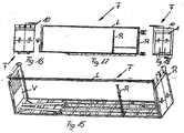
- FIGS. 2 and 3 the rear wall of a vehicle body according to an embodiment is shown, the two hinged door leaves 8 and 9 having corresponding locking bars 8.1 and 8.2 or 9.1 and 9.2. These locking bars engage in respective support rods of a gantry beam 10, which will be described in greater detail with reference to FIGS FIGS. 12, 13 and 14 will be explained.
- the rear wing doors 8 and 9 are hinged on hinges 8.3 and 9.3 to Eckrept 11 of the vehicle body.
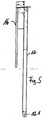
- Eckrache 11 are height or variable in length formed, after appropriate activation of the power lift 1, 2, 3 and 4 and moving out of the push rods 1.1, 2.1, 3.1 and 4.1. This points out Fig. 4 apparent Eckrunge a thrust piece 12 and a key element 13, on which the thrust piece 12 can slide along height.
- the key element 13 has a number of keyholes 14, which in the illustration Fig. 4 are partially hidden due to the altitude taken there.
- the thrust piece 13 is recessed in the Eckrunge 11, including the Eckrunge 11 has a slot or slot-shaped opening 11.1.
- the apparent otherwise in the upper part of the Eckrunge 11 thrust piece 12 is largely covered.
- the thrust piece 12 is assigned a key 17. This has lateral angled projections 17.2, so that there is a groove-shaped receptacle 17.3 between the projections 17.1 and the bends 17.2.
- the slots 14.1 of the key element 13 are open at the bottom so that the key 17 formed as a sliding element can be introduced from below, whereafter it receives the slots 14.1 of the key element 13 with its receivers 17.3. If he has reached a corresponding height, which corresponds to a certain height, he can be pressed into the keyholes 14 with its projections, so that the key 12 is locked in this position.
- the thrust piece 12 due to its gravity after pressure release of the power lift in a lowered position, it can be supported on the locked key 17 as an abutment, so that this corresponds to the adjusted height position of the corner post 11. This is also the set height of the commercial vehicle body and thus the Hubdaches and the portal beam 10, which will be explained in more detail.
- the key 17 In the locked position, the key 17 can be additionally secured, for example via a screw which engages in the hole 17.4.
- a loop 17.5 is provided in the illustrated embodiment.
- Fig. 11 closer to a generally designated 18 tension rod is shown.
- This has a tension rod tube 19 and a tensioning roller 20 located within the tension rod tube 19.
- the tension rod 18 has bores 21 in which locking elements of the tension rod tube 19 are to be introduced.
- the tension roller 20 is to move relative to the tension rod tube 19.
- the tension rod 18 has in its lower portion a head piece 22 which is formed as a square, and which is inserted into a corresponding square socket of the vehicle body in the assembled state of the parts. In the rest, the side wall surrounds a Eckrunge 11.
- a lever 23 is provided which acts with the non-visible locking element. This is to push in and out and is secured by a locking ring 24.
- the tension rod tube 19 has a slot-shaped receptacle, so that a corresponding piping can be inserted into the tension roller 20, so that all parts are to be arranged protected.
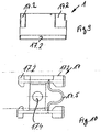
- the as from Fig. 13 is formed as an angled profile body which is to pivot about a horizontal axis 10.
- This gantry 10 has several superimposed locking receptacles 10.1, the latch finger 27 of door locking elements 8.1, 8.2, 9.1, 9.2. to be penetrated.
- the portal beam 10 itself is designed as a box with a front wall 10.2 and a rear wall 10.3 and an inner support rod 10.4, which can be encompassed by the locking finger 27. The fact that this is designed to be pivotable, even with increased Nutzlegiaubau, as he Fig.
- the gantry beam 10 When the lifting roof is lowered, the gantry beam 10 extends substantially behind the door 9, in which case the upper receptacle 10.1 of the gantry beam 10 is used by the locking finger 27.
- the box interior 10.6 bearing blocks 10.7 are provided which extend from the front wall 10.2 to the rear wall 10.3 and stiffen the entire structure and also serve as a centering for the locking fingers 27.
Landscapes
- Engineering & Computer Science (AREA)
- Mechanical Engineering (AREA)
- Chemical & Material Sciences (AREA)
- Combustion & Propulsion (AREA)
- Transportation (AREA)
- Body Structure For Vehicles (AREA)
- Lock And Its Accessories (AREA)
- Power-Operated Mechanisms For Wings (AREA)
Priority Applications (1)
| Application Number | Priority Date | Filing Date | Title |
|---|---|---|---|
| PL09008029T PL2149490T5 (pl) | 2008-07-31 | 2009-06-19 | Nadbudowa pojazdu użytkowego z kłonicami narożnymi, umożliwiającymi regulację wysokości |
Applications Claiming Priority (3)
| Application Number | Priority Date | Filing Date | Title |
|---|---|---|---|
| DE102008035769.3A DE102008035769C5 (de) | 2008-07-31 | 2008-07-31 | Fahrzeugaufbau für Nutzfahrzeuge |
| DE102008035767A DE102008035767A1 (de) | 2008-07-31 | 2008-07-31 | Fahrzeugaufbau für Nutzfahrzeuge |
| DE102008035768A DE102008035768A1 (de) | 2008-07-31 | 2008-07-31 | Fahrzeugaufbau für Nutzfahrzeuge |
Publications (3)
| Publication Number | Publication Date |
|---|---|
| EP2149490A1 EP2149490A1 (de) | 2010-02-03 |
| EP2149490B1 EP2149490B1 (de) | 2013-02-13 |
| EP2149490B2 true EP2149490B2 (de) | 2017-05-10 |
Family
ID=41050290
Family Applications (1)
| Application Number | Title | Priority Date | Filing Date |
|---|---|---|---|
| EP09008029.2A Active EP2149490B2 (de) | 2008-07-31 | 2009-06-19 | Fahrzeugaufbau für Nutzfahrzeuge mit höhenverstellbaren Eckrungen |
Country Status (4)
| Country | Link |
|---|---|
| EP (1) | EP2149490B2 (pl) |
| DK (1) | DK2149490T4 (pl) |
| ES (1) | ES2404581T5 (pl) |
| PL (1) | PL2149490T5 (pl) |
Families Citing this family (3)
| Publication number | Priority date | Publication date | Assignee | Title |
|---|---|---|---|---|
| DE102016108828A1 (de) * | 2016-05-12 | 2017-11-16 | Fahrzeugwerk Bernard Krone GmbH & Co. KG | Nutzfahrzeugaufbau |
| ES2878121T3 (es) | 2018-03-29 | 2021-11-18 | Schmitz Cargobull Ag | Elemento de cierre de lona, lona y carrocería de vehículo |
| FR3096939B1 (fr) * | 2019-06-04 | 2024-12-13 | Soc Ind Dapplications Mecaniques | Benne a rehausse mobile |
Citations (5)
| Publication number | Priority date | Publication date | Assignee | Title |
|---|---|---|---|---|
| DE19922513C1 (de) † | 1999-05-15 | 2000-12-28 | Schmitz Cargobull Ag | Eckrunge mit höhenverstellbarem Schiebling |
| DE10210773C1 (de) † | 2002-03-12 | 2003-08-14 | Schmitz Cargobull Ag | Aufrollstab für Planenfahrzeuge |
| DE10211211A1 (de) † | 2002-03-13 | 2003-10-09 | Schmitz Cargobull Ag | Höhenverstellbares Säulenelement für ein Lastfahrzeug |
| DE10241754B3 (de) † | 2002-09-10 | 2004-03-11 | Schmitz Cargobull Ag | Höhenverstellbare Rungensäule für ein Lastfahrzeug |
| DE10247479A1 (de) † | 2002-10-11 | 2004-04-22 | Fahrzeugwerk Bernard Krone Gmbh | Fahrzeugaufbau für Nutzfahrzeuge |
Family Cites Families (1)
| Publication number | Priority date | Publication date | Assignee | Title |
|---|---|---|---|---|
| DE3138338A1 (de) | 1981-09-26 | 1983-04-07 | Claus H. 2072 Bargteheide Müller | "nutzfahrzeug, wie lastkraftwagen oder anhaenger" |
-
2009
- 2009-06-19 PL PL09008029T patent/PL2149490T5/pl unknown
- 2009-06-19 ES ES09008029.2T patent/ES2404581T5/es active Active
- 2009-06-19 DK DK09008029.2T patent/DK2149490T4/da active
- 2009-06-19 EP EP09008029.2A patent/EP2149490B2/de active Active
Patent Citations (5)
| Publication number | Priority date | Publication date | Assignee | Title |
|---|---|---|---|---|
| DE19922513C1 (de) † | 1999-05-15 | 2000-12-28 | Schmitz Cargobull Ag | Eckrunge mit höhenverstellbarem Schiebling |
| DE10210773C1 (de) † | 2002-03-12 | 2003-08-14 | Schmitz Cargobull Ag | Aufrollstab für Planenfahrzeuge |
| DE10211211A1 (de) † | 2002-03-13 | 2003-10-09 | Schmitz Cargobull Ag | Höhenverstellbares Säulenelement für ein Lastfahrzeug |
| DE10241754B3 (de) † | 2002-09-10 | 2004-03-11 | Schmitz Cargobull Ag | Höhenverstellbare Rungensäule für ein Lastfahrzeug |
| DE10247479A1 (de) † | 2002-10-11 | 2004-04-22 | Fahrzeugwerk Bernard Krone Gmbh | Fahrzeugaufbau für Nutzfahrzeuge |
Non-Patent Citations (2)
| Title |
|---|
| Betriebsanleitung "Planenauflieger", Schmitz Cargobull AG, Nr. BA 919316, Druckvermerk 11/05 † |
| V. BRAUN: "Der Internationale", KFZ-ANZEIGER, vol. 17, 2007, pages 38 - 41 † |
Also Published As
| Publication number | Publication date |
|---|---|
| ES2404581T3 (es) | 2013-05-28 |
| DK2149490T3 (da) | 2013-05-21 |
| DK2149490T4 (da) | 2017-07-31 |
| EP2149490A1 (de) | 2010-02-03 |
| PL2149490T3 (pl) | 2013-07-31 |
| ES2404581T5 (es) | 2017-07-28 |
| PL2149490T5 (pl) | 2017-10-31 |
| EP2149490B1 (de) | 2013-02-13 |
Similar Documents
| Publication | Publication Date | Title |
|---|---|---|
| EP3412830B1 (de) | Baumaschine mit bedienstand und zugangsschutz | |
| EP3599129A1 (de) | Tischvorrichtung für ein kraftfahrzeug | |
| EP0893302A2 (de) | Ausziehbarer Ladeboden für ein Fahrzeug | |
| EP2829663B1 (de) | Oberwagen für eine Baumaschine | |
| EP2151371B1 (de) | Fahrzeugaufbau für Nutzfahrzeuge mit höhenverstellbaren Eckrungen | |
| EP2149490B2 (de) | Fahrzeugaufbau für Nutzfahrzeuge mit höhenverstellbaren Eckrungen | |
| EP1159887B1 (de) | Klapptisch | |
| EP1955932B1 (de) | Schließanordnung für einen Fahrzeugaufbau | |
| EP2151372B1 (de) | Fahrzeugaufbau für Nutzfahrzeuge mit schwenkbarem heckseitigen Portal Balken von hinteren Türflügel | |
| DE102008035769B4 (de) | Fahrzeugaufbau für Nutzfahrzeuge | |
| DE102021114915A1 (de) | Freizeitfahrzeug | |
| EP2676824A2 (de) | Aufbau zum Befördern von Gütern | |
| EP1847418B1 (de) | Ladegutsicherung an Transportfahrzeugen | |
| EP2708393B1 (de) | Fahrzeugaufbau für den Transport von schütt- oder stapelbaren Transportgütern | |
| EP1752325B1 (de) | Dachsystem für einen Personenkraftwagen | |
| DE202017106515U1 (de) | Ladebodeneinheit für ein Bestattungsfahrzeug | |
| DE202008017440U1 (de) | Fahrzeugaufbau für Nutzfahrzeuge | |
| DE10360179B4 (de) | Vorrichtung zum Betätigen eines Paniktürverschlusses | |
| DE102005021117A1 (de) | Kraftfahrzeug | |
| DE4221516A1 (de) | Bettkonstruktion | |
| DE29815740U1 (de) | Schiebebügelverdeck für LKW oder Anhänger | |
| DE102010024506B4 (de) | Gepäckraumabdeckung für ein Kraftfahrzeug | |
| DE102010037515A1 (de) | Schließanordnung für einen Fahrzeugaufbau | |
| EP1743611A1 (de) | Ausfahrbare Einstiegsrampe für Fahrzeuge des öffentlichen Personenverkehrs | |
| DE19825071A1 (de) | Parallelausstellfenster mit Drehfunktion |
Legal Events
| Date | Code | Title | Description |
|---|---|---|---|
| PUAI | Public reference made under article 153(3) epc to a published international application that has entered the european phase |
Free format text: ORIGINAL CODE: 0009012 |
|
| 17P | Request for examination filed |
Effective date: 20091024 |
|
| AK | Designated contracting states |
Kind code of ref document: A1 Designated state(s): AT BE BG CH CY CZ DE DK EE ES FI FR GB GR HR HU IE IS IT LI LT LU LV MC MK MT NL NO PL PT RO SE SI SK TR |
|
| AX | Request for extension of the european patent |
Extension state: AL BA RS |
|
| 17Q | First examination report despatched |
Effective date: 20101108 |
|
| GRAP | Despatch of communication of intention to grant a patent |
Free format text: ORIGINAL CODE: EPIDOSNIGR1 |
|
| RIN1 | Information on inventor provided before grant (corrected) |
Inventor name: MENKE, ANSGAR Inventor name: IRION, MANFRED |
|
| GRAS | Grant fee paid |
Free format text: ORIGINAL CODE: EPIDOSNIGR3 |
|
| GRAA | (expected) grant |
Free format text: ORIGINAL CODE: 0009210 |
|
| AK | Designated contracting states |
Kind code of ref document: B1 Designated state(s): AT BE BG CH CY CZ DE DK EE ES FI FR GB GR HR HU IE IS IT LI LT LU LV MC MK MT NL NO PL PT RO SE SI SK TR |
|
| REG | Reference to a national code |
Ref country code: GB Ref legal event code: FG4D Free format text: NOT ENGLISH |
|
| REG | Reference to a national code |
Ref country code: AT Ref legal event code: REF Ref document number: 596307 Country of ref document: AT Kind code of ref document: T Effective date: 20130215 |
|
| REG | Reference to a national code |
Ref country code: IE Ref legal event code: FG4D Free format text: LANGUAGE OF EP DOCUMENT: GERMAN |
|
| REG | Reference to a national code |
Ref country code: DE Ref legal event code: R096 Ref document number: 502009006186 Country of ref document: DE Effective date: 20130411 |
|
| REG | Reference to a national code |
Ref country code: SE Ref legal event code: TRGR |
|
| REG | Reference to a national code |
Ref country code: DK Ref legal event code: T3 |
|
| REG | Reference to a national code |
Ref country code: NL Ref legal event code: T3 |
|
| REG | Reference to a national code |
Ref country code: ES Ref legal event code: FG2A Ref document number: 2404581 Country of ref document: ES Kind code of ref document: T3 Effective date: 20130528 |
|
| REG | Reference to a national code |
Ref country code: LT Ref legal event code: MG4D |
|
| PG25 | Lapsed in a contracting state [announced via postgrant information from national office to epo] |
Ref country code: LT Free format text: LAPSE BECAUSE OF FAILURE TO SUBMIT A TRANSLATION OF THE DESCRIPTION OR TO PAY THE FEE WITHIN THE PRESCRIBED TIME-LIMIT Effective date: 20130213 Ref country code: IS Free format text: LAPSE BECAUSE OF FAILURE TO SUBMIT A TRANSLATION OF THE DESCRIPTION OR TO PAY THE FEE WITHIN THE PRESCRIBED TIME-LIMIT Effective date: 20130613 Ref country code: BG Free format text: LAPSE BECAUSE OF FAILURE TO SUBMIT A TRANSLATION OF THE DESCRIPTION OR TO PAY THE FEE WITHIN THE PRESCRIBED TIME-LIMIT Effective date: 20130513 Ref country code: NO Free format text: LAPSE BECAUSE OF FAILURE TO SUBMIT A TRANSLATION OF THE DESCRIPTION OR TO PAY THE FEE WITHIN THE PRESCRIBED TIME-LIMIT Effective date: 20130513 |
|
| REG | Reference to a national code |
Ref country code: PL Ref legal event code: T3 |
|
| PG25 | Lapsed in a contracting state [announced via postgrant information from national office to epo] |
Ref country code: PT Free format text: LAPSE BECAUSE OF FAILURE TO SUBMIT A TRANSLATION OF THE DESCRIPTION OR TO PAY THE FEE WITHIN THE PRESCRIBED TIME-LIMIT Effective date: 20130613 Ref country code: FI Free format text: LAPSE BECAUSE OF FAILURE TO SUBMIT A TRANSLATION OF THE DESCRIPTION OR TO PAY THE FEE WITHIN THE PRESCRIBED TIME-LIMIT Effective date: 20130213 Ref country code: GR Free format text: LAPSE BECAUSE OF FAILURE TO SUBMIT A TRANSLATION OF THE DESCRIPTION OR TO PAY THE FEE WITHIN THE PRESCRIBED TIME-LIMIT Effective date: 20130514 Ref country code: LV Free format text: LAPSE BECAUSE OF FAILURE TO SUBMIT A TRANSLATION OF THE DESCRIPTION OR TO PAY THE FEE WITHIN THE PRESCRIBED TIME-LIMIT Effective date: 20130213 Ref country code: SI Free format text: LAPSE BECAUSE OF FAILURE TO SUBMIT A TRANSLATION OF THE DESCRIPTION OR TO PAY THE FEE WITHIN THE PRESCRIBED TIME-LIMIT Effective date: 20130213 |
|
| PG25 | Lapsed in a contracting state [announced via postgrant information from national office to epo] |
Ref country code: HR Free format text: LAPSE BECAUSE OF FAILURE TO SUBMIT A TRANSLATION OF THE DESCRIPTION OR TO PAY THE FEE WITHIN THE PRESCRIBED TIME-LIMIT Effective date: 20130213 |
|
| PG25 | Lapsed in a contracting state [announced via postgrant information from national office to epo] |
Ref country code: RO Free format text: LAPSE BECAUSE OF FAILURE TO SUBMIT A TRANSLATION OF THE DESCRIPTION OR TO PAY THE FEE WITHIN THE PRESCRIBED TIME-LIMIT Effective date: 20130213 Ref country code: SK Free format text: LAPSE BECAUSE OF FAILURE TO SUBMIT A TRANSLATION OF THE DESCRIPTION OR TO PAY THE FEE WITHIN THE PRESCRIBED TIME-LIMIT Effective date: 20130213 Ref country code: EE Free format text: LAPSE BECAUSE OF FAILURE TO SUBMIT A TRANSLATION OF THE DESCRIPTION OR TO PAY THE FEE WITHIN THE PRESCRIBED TIME-LIMIT Effective date: 20130213 Ref country code: CZ Free format text: LAPSE BECAUSE OF FAILURE TO SUBMIT A TRANSLATION OF THE DESCRIPTION OR TO PAY THE FEE WITHIN THE PRESCRIBED TIME-LIMIT Effective date: 20130213 |
|
| PLBI | Opposition filed |
Free format text: ORIGINAL CODE: 0009260 |
|
| PLAX | Notice of opposition and request to file observation + time limit sent |
Free format text: ORIGINAL CODE: EPIDOSNOBS2 |
|
| 26 | Opposition filed |
Opponent name: SCHMITZ CARGOBULL AG Effective date: 20131113 |
|
| PG25 | Lapsed in a contracting state [announced via postgrant information from national office to epo] |
Ref country code: MC Free format text: LAPSE BECAUSE OF FAILURE TO SUBMIT A TRANSLATION OF THE DESCRIPTION OR TO PAY THE FEE WITHIN THE PRESCRIBED TIME-LIMIT Effective date: 20130213 |
|
| REG | Reference to a national code |
Ref country code: CH Ref legal event code: PL |
|
| REG | Reference to a national code |
Ref country code: DE Ref legal event code: R026 Ref document number: 502009006186 Country of ref document: DE Effective date: 20131113 |
|
| REG | Reference to a national code |
Ref country code: IE Ref legal event code: MM4A |
|
| PLAF | Information modified related to communication of a notice of opposition and request to file observations + time limit |
Free format text: ORIGINAL CODE: EPIDOSCOBS2 |
|
| PG25 | Lapsed in a contracting state [announced via postgrant information from national office to epo] |
Ref country code: LI Free format text: LAPSE BECAUSE OF NON-PAYMENT OF DUE FEES Effective date: 20130630 Ref country code: CH Free format text: LAPSE BECAUSE OF NON-PAYMENT OF DUE FEES Effective date: 20130630 Ref country code: IE Free format text: LAPSE BECAUSE OF NON-PAYMENT OF DUE FEES Effective date: 20130619 |
|
| PLBB | Reply of patent proprietor to notice(s) of opposition received |
Free format text: ORIGINAL CODE: EPIDOSNOBS3 |
|
| PG25 | Lapsed in a contracting state [announced via postgrant information from national office to epo] |
Ref country code: MT Free format text: LAPSE BECAUSE OF FAILURE TO SUBMIT A TRANSLATION OF THE DESCRIPTION OR TO PAY THE FEE WITHIN THE PRESCRIBED TIME-LIMIT Effective date: 20130213 |
|
| PG25 | Lapsed in a contracting state [announced via postgrant information from national office to epo] |
Ref country code: CY Free format text: LAPSE BECAUSE OF FAILURE TO SUBMIT A TRANSLATION OF THE DESCRIPTION OR TO PAY THE FEE WITHIN THE PRESCRIBED TIME-LIMIT Effective date: 20130213 |
|
| PG25 | Lapsed in a contracting state [announced via postgrant information from national office to epo] |
Ref country code: HU Free format text: LAPSE BECAUSE OF FAILURE TO SUBMIT A TRANSLATION OF THE DESCRIPTION OR TO PAY THE FEE WITHIN THE PRESCRIBED TIME-LIMIT; INVALID AB INITIO Effective date: 20090619 Ref country code: MK Free format text: LAPSE BECAUSE OF FAILURE TO SUBMIT A TRANSLATION OF THE DESCRIPTION OR TO PAY THE FEE WITHIN THE PRESCRIBED TIME-LIMIT Effective date: 20130213 Ref country code: LU Free format text: LAPSE BECAUSE OF NON-PAYMENT OF DUE FEES Effective date: 20130619 |
|
| REG | Reference to a national code |
Ref country code: FR Ref legal event code: PLFP Year of fee payment: 8 |
|
| PUAH | Patent maintained in amended form |
Free format text: ORIGINAL CODE: 0009272 |
|
| STAA | Information on the status of an ep patent application or granted ep patent |
Free format text: STATUS: PATENT MAINTAINED AS AMENDED |
|
| 27A | Patent maintained in amended form |
Effective date: 20170510 |
|
| AK | Designated contracting states |
Kind code of ref document: B2 Designated state(s): AT BE BG CH CY CZ DE DK EE ES FI FR GB GR HR HU IE IS IT LI LT LU LV MC MK MT NL NO PL PT RO SE SI SK TR |
|
| REG | Reference to a national code |
Ref country code: DE Ref legal event code: R102 Ref document number: 502009006186 Country of ref document: DE |
|
| REG | Reference to a national code |
Ref country code: FR Ref legal event code: PLFP Year of fee payment: 9 |
|
| REG | Reference to a national code |
Ref country code: NL Ref legal event code: FP |
|
| REG | Reference to a national code |
Ref country code: ES Ref legal event code: DC2A Ref document number: 2404581 Country of ref document: ES Kind code of ref document: T5 Effective date: 20170728 |
|
| REG | Reference to a national code |
Ref country code: DK Ref legal event code: T4 Effective date: 20170728 |
|
| REG | Reference to a national code |
Ref country code: SE Ref legal event code: RPEO |
|
| REG | Reference to a national code |
Ref country code: FR Ref legal event code: PLFP Year of fee payment: 10 |
|
| P01 | Opt-out of the competence of the unified patent court (upc) registered |
Effective date: 20230518 |
|
| PGFP | Annual fee paid to national office [announced via postgrant information from national office to epo] |
Ref country code: DE Payment date: 20250618 Year of fee payment: 17 Ref country code: PL Payment date: 20250606 Year of fee payment: 17 |
|
| PGFP | Annual fee paid to national office [announced via postgrant information from national office to epo] |
Ref country code: GB Payment date: 20250620 Year of fee payment: 17 Ref country code: DK Payment date: 20250618 Year of fee payment: 17 |
|
| PGFP | Annual fee paid to national office [announced via postgrant information from national office to epo] |
Ref country code: NL Payment date: 20250618 Year of fee payment: 17 Ref country code: BE Payment date: 20250617 Year of fee payment: 17 |
|
| PGFP | Annual fee paid to national office [announced via postgrant information from national office to epo] |
Ref country code: FR Payment date: 20250626 Year of fee payment: 17 |
|
| PGFP | Annual fee paid to national office [announced via postgrant information from national office to epo] |
Ref country code: AT Payment date: 20250616 Year of fee payment: 17 |
|
| PGFP | Annual fee paid to national office [announced via postgrant information from national office to epo] |
Ref country code: TR Payment date: 20250617 Year of fee payment: 17 |
|
| PGFP | Annual fee paid to national office [announced via postgrant information from national office to epo] |
Ref country code: SE Payment date: 20250618 Year of fee payment: 17 |
|
| PGFP | Annual fee paid to national office [announced via postgrant information from national office to epo] |
Ref country code: ES Payment date: 20250718 Year of fee payment: 17 |
|
| PGFP | Annual fee paid to national office [announced via postgrant information from national office to epo] |
Ref country code: IT Payment date: 20250630 Year of fee payment: 17 |