EP2145857A1 - Method of manufacturing a micromechanical part - Google Patents
Method of manufacturing a micromechanical part Download PDFInfo
- Publication number
- EP2145857A1 EP2145857A1 EP08160143A EP08160143A EP2145857A1 EP 2145857 A1 EP2145857 A1 EP 2145857A1 EP 08160143 A EP08160143 A EP 08160143A EP 08160143 A EP08160143 A EP 08160143A EP 2145857 A1 EP2145857 A1 EP 2145857A1
- Authority
- EP
- European Patent Office
- Prior art keywords
- substrate
- support
- steps
- alignment means
- micro
- Prior art date
- Legal status (The legal status is an assumption and is not a legal conclusion. Google has not performed a legal analysis and makes no representation as to the accuracy of the status listed.)
- Granted
Links
- 238000004519 manufacturing process Methods 0.000 title claims description 18
- 239000000758 substrate Substances 0.000 claims abstract description 96
- 239000000463 material Substances 0.000 claims abstract description 44
- 238000000034 method Methods 0.000 claims abstract description 40
- 238000005530 etching Methods 0.000 claims abstract description 8
- 238000000206 photolithography Methods 0.000 claims abstract description 6
- 239000011248 coating agent Substances 0.000 claims description 14
- 238000000576 coating method Methods 0.000 claims description 14
- 238000000151 deposition Methods 0.000 claims description 9
- 230000001681 protective effect Effects 0.000 claims description 9
- 238000006073 displacement reaction Methods 0.000 claims description 6
- 229910021419 crystalline silicon Inorganic materials 0.000 claims description 5
- VYPSYNLAJGMNEJ-UHFFFAOYSA-N Silicium dioxide Chemical compound O=[Si]=O VYPSYNLAJGMNEJ-UHFFFAOYSA-N 0.000 claims description 4
- 235000012239 silicon dioxide Nutrition 0.000 claims description 4
- PNEYBMLMFCGWSK-UHFFFAOYSA-N aluminium oxide Inorganic materials [O-2].[O-2].[O-2].[Al+3].[Al+3] PNEYBMLMFCGWSK-UHFFFAOYSA-N 0.000 claims description 3
- 229910002026 crystalline silica Inorganic materials 0.000 claims description 3
- GNFTZDOKVXKIBK-UHFFFAOYSA-N 3-(2-methoxyethoxy)benzohydrazide Chemical compound COCCOC1=CC=CC(C(=O)NN)=C1 GNFTZDOKVXKIBK-UHFFFAOYSA-N 0.000 claims description 2
- 239000011347 resin Substances 0.000 claims description 2
- 229920005989 resin Polymers 0.000 claims description 2
- 239000011800 void material Substances 0.000 claims 2
- 229910052799 carbon Inorganic materials 0.000 description 4
- OKTJSMMVPCPJKN-UHFFFAOYSA-N Carbon Chemical compound [C] OKTJSMMVPCPJKN-UHFFFAOYSA-N 0.000 description 3
- 230000008021 deposition Effects 0.000 description 3
- 229910003460 diamond Inorganic materials 0.000 description 3
- 239000010432 diamond Substances 0.000 description 3
- 229910021421 monocrystalline silicon Inorganic materials 0.000 description 3
- 238000012550 audit Methods 0.000 description 2
- 229910021387 carbon allotrope Inorganic materials 0.000 description 2
- 238000000708 deep reactive-ion etching Methods 0.000 description 2
- 238000010586 diagram Methods 0.000 description 2
- 238000005240 physical vapour deposition Methods 0.000 description 2
- XUIMIQQOPSSXEZ-UHFFFAOYSA-N Silicon Chemical compound [Si] XUIMIQQOPSSXEZ-UHFFFAOYSA-N 0.000 description 1
- 239000000853 adhesive Substances 0.000 description 1
- 230000001070 adhesive effect Effects 0.000 description 1
- HIGRAKVNKLCVCA-UHFFFAOYSA-N alumine Chemical compound C1=CC=[Al]C=C1 HIGRAKVNKLCVCA-UHFFFAOYSA-N 0.000 description 1
- 229910003481 amorphous carbon Inorganic materials 0.000 description 1
- 239000000919 ceramic Substances 0.000 description 1
- 238000005229 chemical vapour deposition Methods 0.000 description 1
- 239000010431 corundum Substances 0.000 description 1
- 229910052593 corundum Inorganic materials 0.000 description 1
- 230000003247 decreasing effect Effects 0.000 description 1
- 230000000694 effects Effects 0.000 description 1
- 230000003028 elevating effect Effects 0.000 description 1
- 230000002349 favourable effect Effects 0.000 description 1
- 238000010438 heat treatment Methods 0.000 description 1
- 239000007769 metal material Substances 0.000 description 1
- 238000012986 modification Methods 0.000 description 1
- 230000004048 modification Effects 0.000 description 1
- 229920000642 polymer Polymers 0.000 description 1
- 239000010453 quartz Substances 0.000 description 1
- 230000005855 radiation Effects 0.000 description 1
- 229910052594 sapphire Inorganic materials 0.000 description 1
- 239000010980 sapphire Substances 0.000 description 1
- 239000002210 silicon-based material Substances 0.000 description 1
- 239000000126 substance Substances 0.000 description 1
- 229910052715 tantalum Inorganic materials 0.000 description 1
- GUVRBAGPIYLISA-UHFFFAOYSA-N tantalum atom Chemical compound [Ta] GUVRBAGPIYLISA-UHFFFAOYSA-N 0.000 description 1
- WFKWXMTUELFFGS-UHFFFAOYSA-N tungsten Chemical compound [W] WFKWXMTUELFFGS-UHFFFAOYSA-N 0.000 description 1
- 229910052721 tungsten Inorganic materials 0.000 description 1
- 239000010937 tungsten Substances 0.000 description 1
Images


Classifications
-
- G—PHYSICS
- G04—HOROLOGY
- G04D—APPARATUS OR TOOLS SPECIALLY DESIGNED FOR MAKING OR MAINTAINING CLOCKS OR WATCHES
- G04D3/00—Watchmakers' or watch-repairers' machines or tools for working materials
- G04D3/0002—Watchmakers' or watch-repairers' machines or tools for working materials for mechanical working other than with a lathe
- G04D3/0017—Watchmakers' or watch-repairers' machines or tools for working materials for mechanical working other than with a lathe for components of gearworks
- G04D3/002—Watchmakers' or watch-repairers' machines or tools for working materials for mechanical working other than with a lathe for components of gearworks for gear wheels or gears
-
- B—PERFORMING OPERATIONS; TRANSPORTING
- B81—MICROSTRUCTURAL TECHNOLOGY
- B81C—PROCESSES OR APPARATUS SPECIALLY ADAPTED FOR THE MANUFACTURE OR TREATMENT OF MICROSTRUCTURAL DEVICES OR SYSTEMS
- B81C3/00—Assembling of devices or systems from individually processed components
- B81C3/008—Aspects related to assembling from individually processed components, not covered by groups B81C3/001 - B81C3/002
-
- B—PERFORMING OPERATIONS; TRANSPORTING
- B81—MICROSTRUCTURAL TECHNOLOGY
- B81C—PROCESSES OR APPARATUS SPECIALLY ADAPTED FOR THE MANUFACTURE OR TREATMENT OF MICROSTRUCTURAL DEVICES OR SYSTEMS
- B81C99/00—Subject matter not provided for in other groups of this subclass
- B81C99/0075—Manufacture of substrate-free structures
- B81C99/008—Manufacture of substrate-free structures separating the processed structure from a mother substrate
-
- G—PHYSICS
- G03—PHOTOGRAPHY; CINEMATOGRAPHY; ANALOGOUS TECHNIQUES USING WAVES OTHER THAN OPTICAL WAVES; ELECTROGRAPHY; HOLOGRAPHY
- G03F—PHOTOMECHANICAL PRODUCTION OF TEXTURED OR PATTERNED SURFACES, e.g. FOR PRINTING, FOR PROCESSING OF SEMICONDUCTOR DEVICES; MATERIALS THEREFOR; ORIGINALS THEREFOR; APPARATUS SPECIALLY ADAPTED THEREFOR
- G03F7/00—Photomechanical, e.g. photolithographic, production of textured or patterned surfaces, e.g. printing surfaces; Materials therefor, e.g. comprising photoresists; Apparatus specially adapted therefor
- G03F7/0002—Lithographic processes using patterning methods other than those involving the exposure to radiation, e.g. by stamping
-
- G—PHYSICS
- G04—HOROLOGY
- G04B—MECHANICALLY-DRIVEN CLOCKS OR WATCHES; MECHANICAL PARTS OF CLOCKS OR WATCHES IN GENERAL; TIME PIECES USING THE POSITION OF THE SUN, MOON OR STARS
- G04B13/00—Gearwork
- G04B13/02—Wheels; Pinions; Spindles; Pivots
-
- G—PHYSICS
- G04—HOROLOGY
- G04B—MECHANICALLY-DRIVEN CLOCKS OR WATCHES; MECHANICAL PARTS OF CLOCKS OR WATCHES IN GENERAL; TIME PIECES USING THE POSITION OF THE SUN, MOON OR STARS
- G04B15/00—Escapements
- G04B15/14—Component parts or constructional details, e.g. construction of the lever or the escape wheel
-
- G—PHYSICS
- G04—HOROLOGY
- G04D—APPARATUS OR TOOLS SPECIALLY DESIGNED FOR MAKING OR MAINTAINING CLOCKS OR WATCHES
- G04D1/00—Gripping, holding, or supporting devices
-
- G—PHYSICS
- G04—HOROLOGY
- G04D—APPARATUS OR TOOLS SPECIALLY DESIGNED FOR MAKING OR MAINTAINING CLOCKS OR WATCHES
- G04D3/00—Watchmakers' or watch-repairers' machines or tools for working materials
- G04D3/0002—Watchmakers' or watch-repairers' machines or tools for working materials for mechanical working other than with a lathe
- G04D3/0028—Watchmakers' or watch-repairers' machines or tools for working materials for mechanical working other than with a lathe for components of the escape mechanism
- G04D3/0033—Watchmakers' or watch-repairers' machines or tools for working materials for mechanical working other than with a lathe for components of the escape mechanism for lever wheels
-
- G—PHYSICS
- G04—HOROLOGY
- G04D—APPARATUS OR TOOLS SPECIALLY DESIGNED FOR MAKING OR MAINTAINING CLOCKS OR WATCHES
- G04D3/00—Watchmakers' or watch-repairers' machines or tools for working materials
- G04D3/0069—Watchmakers' or watch-repairers' machines or tools for working materials for working with non-mechanical means, e.g. chemical, electrochemical, metallising, vapourising; with electron beams, laser beams
-
- B—PERFORMING OPERATIONS; TRANSPORTING
- B81—MICROSTRUCTURAL TECHNOLOGY
- B81B—MICROSTRUCTURAL DEVICES OR SYSTEMS, e.g. MICROMECHANICAL DEVICES
- B81B2201/00—Specific applications of microelectromechanical systems
- B81B2201/03—Microengines and actuators
- B81B2201/035—Microgears
-
- B—PERFORMING OPERATIONS; TRANSPORTING
- B81—MICROSTRUCTURAL TECHNOLOGY
- B81C—PROCESSES OR APPARATUS SPECIALLY ADAPTED FOR THE MANUFACTURE OR TREATMENT OF MICROSTRUCTURAL DEVICES OR SYSTEMS
- B81C2201/00—Manufacture or treatment of microstructural devices or systems
- B81C2201/11—Treatments for avoiding stiction of elastic or moving parts of MEMS
- B81C2201/112—Depositing an anti-stiction or passivation coating, e.g. on the elastic or moving parts
-
- Y—GENERAL TAGGING OF NEW TECHNOLOGICAL DEVELOPMENTS; GENERAL TAGGING OF CROSS-SECTIONAL TECHNOLOGIES SPANNING OVER SEVERAL SECTIONS OF THE IPC; TECHNICAL SUBJECTS COVERED BY FORMER USPC CROSS-REFERENCE ART COLLECTIONS [XRACs] AND DIGESTS
- Y10—TECHNICAL SUBJECTS COVERED BY FORMER USPC
- Y10T—TECHNICAL SUBJECTS COVERED BY FORMER US CLASSIFICATION
- Y10T29/00—Metal working
- Y10T29/49—Method of mechanical manufacture
- Y10T29/49579—Watch or clock making
- Y10T29/49581—Watch or clock making having arbor, pinion, or balance
Definitions
- the invention relates to a method for manufacturing a mechanical part made from a micro-machinable material and, more particularly, such a part intended to be used for the manufacture of a timepiece.
- the object of the present invention is to overcome all or part of the aforementioned drawbacks by proposing a method which allows, in a simple manner, a prior reliable assembly of the part avoiding any manipulation of its functional parts so that the part is ready to be mounted in a device such as a timepiece without having to touch it.
- the method allows the quality manufacture of a micromechanical component that can be applied to most mechanical watch parts.
- the method 1 comprises mainly six steps 3, 5, 7, 9, 11 and 13 for manufacturing a mechanical part 51 whose core is made from a micro-machinable material.
- a micro-machinable material thanks to its accuracy below one micrometer, is particularly useful for the manufacture of an element, for example, a timepiece and advantageously replaces a metal material usually used.
- the micro-machinable material may be based on crystalline silicon, for example monocrystalline silicon, crystalline silica such as quartz or crystalline alumina such as corundum (also known as sapphire). synthetic). Of course, other micro-machinable materials can be envisaged.
- Step 3 consists in providing a substrate 53 made of micro-machinable material such as, for example, a monocrystalline silicon wafer used for the manufacture of electronic components (also called “wafer” in English).
- a thinning phase is provided in step 3 in order to adapt the final thickness of the part 51.
- Such a phase can be achieved by a mechanical or chemical lapping method (also known as " back lapping ").
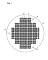
- Step 5 consists in making, by photolithography, in the entire thickness of the substrate 53, a pattern 50 comprising the mechanical part 51 to be manufactured.
- a pattern 50 comprising the mechanical part 51 to be manufactured.
- the larger size of the substrate 53 relative to that of the part 51 allows the etching of several patterns 50 and thus the manufacture of several pieces 51 from the same substrate 53.
- each mechanical part 51 is an escape wheel for a timepiece.
- the method 1 makes it possible to manufacture other parts of a timepiece but also, as explained hereinafter, several different parts on the same substrate 53.
- Step 7 consists in mounting on a base 55 the etched substrate 53 in order to leave accessible its upper and lower faces.
- This step facilitates the implementation of step 9 of depositing a coating on the outer surface of the piece 51 of better tribological quality than said micro-machinable material.
- the height of the substrate 53 relative to the base 55 facilitates the deposition of the coating in that it facilitates accessibility both on the top, on the thickness and on the underside of each piece 51 .
- Step 9 makes it possible to deposit a coating which advantageously replaces any insufficient tribological qualities of the micro-machinable material.
- Such a coating may be, for example, based on a carbon allotrope. It can thus be envisaged to deposit a crystalline carbon coating, such as synthetic diamond, by chemical vapor deposition (also known as “CVD” abbreviation). It can also be deposited amorphous carbon as carbon in diamond form (also known by the abbreviation “DLC” from the terms “Diamond-Like-Carbon”) by physical vapor deposition (also known by the English abbreviation "PVD”). Of course, one or more other materials can be used in replacing or adjuvanting carbon. Other deposition methods are also conceivable.
- Step 13 is to assemble a fastener 91 on the part 51 with a support 81 so that the pre-assembled part 51 is ready to be mounted without having to touch the part of micro-machinable material.
- Step 11 consists in releasing each piece 51 from the substrate 53.
- escape wheels whose core is of monocrystalline silicon and, according to the embodiments explained hereinafter, comprising a synthetic diamond outer surface and / or a preassembled fastener 91.
- the method 1 comprises the consecutive steps 3, 5, 13 and 11 as illustrated by a single line at the figure 7 .
- the first step 3 is to provide a substrate 53 of micro-machinable material.
- the second step 5 consists of photolithography, in the entire thickness of the substrate 53, the patterns 50 each comprising a mechanical part 51 to manufacture.
- the second step 5 comprises three phases 15, 17 and 19.
- a protective mask is structured on the substrate 53.
- the protective mask is made using a photosensitive resin.
- the protective mask is thus formed using a selective radiation for structuring said shape mask corresponding to each pattern 50 to achieve. With this step 15, it will be possible very accurately to etch any planar shape selectively on the substrate 53.
- a second phase 17 an attack by anisotropic etching of the substrate assembly 53 - protective mask is performed.
- a deep reactive ion etching type attack is used (also known by the abbreviation "DRIE").
- DRIE deep reactive ion etching type attack
- the anisotropic etching makes it possible to substantially rectilinearly etch the substrate 53 at the level of the zones that are not protected by said protective mask.
- the etching during the second phase 17 is carried out over the entire thickness of the substrate 53 and, optionally, along a crystallographic axis of the micro-machinable material favorable to this attack.
- each pattern 50 as illustrated in FIGS. figures 1 and 2 comprises two material bridges 57. These allow the part 51 to be held in relation to the substrate 53 until step 11. As visible in FIG. figure 2 , the material bridges 57 comprise a narrowed section at the end connected to the pattern of the part 51 to create a zone of weakness capable of facilitating the release step 11.
- the second phase 17 is also used to engrave in the substrate 53 holes 59 forming part of the alignment means.
- the second phase 17 is also used to engrave in the substrate 53 holes 59 forming part of the alignment means.
- three holes 59 have been formed distributed substantially at 120 degrees to one another and near the ends of the substrate 53.
- a third and last phase 19 of the second step 5 the protective mask is removed from the surface of the substrate 53.
- a substrate 53 having several patterns 50 comprising a piece 51 secured to the substrate 53 by two material bridges 57 is then obtained. as illustrated in figures 1 and 2 .
- the third step 13 consists in assembling a fastener 91 on the part 51 by means of a support 81 so that the pre-assembled part 51 is ready to be assembled without having to touch the part made of micro-machinable material.
- Step 13 comprises phases 25 and 27.
- the first phase 25 consists in mounting on a support 81, provided with forks 87, the substrate 53 so that teeth 82 of a fork 87 cooperate with each piece 51 and thus facilitate the mounting of the fastener 91.
- a support 81 provided with forks 87, the substrate 53 so that teeth 82 of a fork 87 cooperate with each piece 51 and thus facilitate the mounting of the fastener 91.
- the substrate 53 is guided along the directions E by means of alignment means so as to reliably orient the substrate 53 with respect to the support 81.
- the alignment means are formed by a chamfered column 80, mounted in extension of an axis 85 integral substantially perpendicular to the support 81, which cooperates with one of the recesses 59 made in the substrate 53 in step 5.
- the method 1 comprises three alignment means 80, 59 in order to improve the guiding of the first phase 25.
- the substrate 53 and each piece 51 slide respectively against each axis 85 and each fork 87 all integral with the support 81.
- the second time ends when the substrate 53 and each piece 51 abut substantially respectively against the shoulder 88 of each axis 85 and the shoulder of each fork 87 formed in the bottom of the space 84 that its teeth delimit.
- the substrate 53 and each piece 51 are stably positioned and have as a single degree of freedom the translation D upwards.
- the forks 87 will be adapted.
- the support 81 is formed from a material that does not hurt the part 51 such as, for example, a plastic polymer.
- the alignment means 80, 59 are located vertically higher than the axes 85 and the forks 87 to ensure the consecutivity of the first time then the second time.
- a fastener 91 is assembled on each piece 51.
- FIG. figure 6 we can see a first piece 51 assembled and a second piece 51 more to the right whose attachment 91 is not yet assembled.
- this figure 6 is used for a better understanding.
- the mounting of the fasteners 91 can not be limited to a one-to-one assembly with tweezers 89 but can obviously be performed simultaneously for each piece 51 with the aid of an automaton.
- the fastener 91 is moved according to the translation F to the pierced center 69 of the part 51 contained in the space 84 delimited by the teeth 82.
- the maximum translation of the fastener 91 with respect to the center 69 is delimited by the height of the hole 86 made in extension of the space 84 which makes it possible to reliably mount the fastener 91 with respect to the part 51.
- the fastener 91 and the part 51 are permanently secured, for example, by heating them in an oven so that the adhesive, present on each fastener 91, polymerizes which has the effect of securing each fastener 91 in its associated center 69.
- a substrate 53 is obtained, the part 51 of each pattern 50 of which is pre-assembled.
- the tens of parts 51 are therefore always manipulable together and can be supplied with or without the support 81 directly on a line manufacturing a device, such as, for example, a timepiece movement.
- the fourth and last step 11 consists in exerting a relative displacement between the part 51 and the substrate 53 in order to break the material bridges 57.
- this displacement can be achieved by pulling directly on the fastener 91 which allows the final assembly of each piece 51 without any direct manipulation on the micro-machinable material.
- Step 11 can thus be performed manually using tweezers or using a PLC.
- the part 51 is an escape wheel and the fastener 91, its pivot axis.
- the piece 51 could be another type of gear, a crown or even a spiral-ferrule assembly as well as the fastener 91 could be another piece functional than a pivot axis.
- the second embodiment is provided for the case where the micro-machinable material has insufficient tribological characteristics for the intended application of the part 51.
- the method 1 comprises the consecutive steps 3, 5, 7 , 9, 13 and 11 as illustrated by a double line at figure 7 .
- the first steps 3, 5 remain unchanged with respect to the first embodiment.
- the second embodiment first goes through steps 7 and 9 before going to step 13 which advantageously allows depositing a coating on each of the parts 51 of the substrate 53.
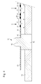
- the third step 7 consists of mounting the etched substrate 53 on a base 55 so as to leave the upper and lower faces of the substrate 53 accessible for the purpose of preparing it for the deposition step 9.
- the base 55 is a plate whose material is capable of withstanding the temperatures of the fourth step 9 such as, for example, a ceramic.
- the latter comprises shafts 61 designed to cooperate with the holes 59 made in the substrate 53 during step 5.
- the axes 61 are preferably in tungsten or tantalum.
- Step 7 comprises phases 21 and 23.
- each generally cylindrical axis 61 has a lower part 63 connected to an upper part 65 of smaller section by means of a shoulder 67.
- the lower part 63 is mounted substantially perpendicularly in the base 55 in a fixed manner.
- the upper part 65 has in extension a chamfered column 60 belonging to alignment means mentioned below.
- the substrate 53 is guided along the directions B by means of alignment means so as to reliably orient the substrate 53 with respect to the base 55.
- the alignment means are formed by the chamfered column 60 cooperating with one of the recesses 59.
- the method 1 comprises three alignment means 60, 59 to improve the guidance of the first phase 21.
- the substrate 53 slides respectively against each portion 65 of the shafts 61 of the base 55 until the substrate 53 abuts substantially against the shoulder 67 of each axis 61 As visible at the figure 3 at the end of step 7, the substrate 53 is stably positioned and has as a single degree of freedom the translation A upwards.
- each column 93 and 97 of substantially trigonal shape cooperates with a different pattern 50 in a central symmetry in order to improve the guidance of step 21.
- the symmetry is made with respect to the center of the substrate 53 and uses the patterns 50 at the top left and bottom right of the example shown in figure 1 .
- the alignment means 60, 59, 93, 97 are located vertically higher than the axes 61 in order to guarantee the consecutivity of the phases 21 and then 23.
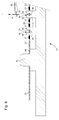
- the fourth step 9 consists in depositing a coating on the outer surface of each piece 51.
- the coating may, for example, be a carbon allotrope intended to improve the tribology of each piece 51, in particular, by decreasing its coefficient of friction.
- step 9 makes it possible to deposit a coating below, over the thickness and above the substrate 53 by virtue of the step 7 of elevating the substrate 53 and the fact that the substrate 53 has been engraved throughout its thickness during step 5.
- the substrate 53 is removed from the base 55 and the second embodiment engages the fifth step 13 in the same manner as the first embodiment.
- a substrate 53 is obtained, the piece 51 of micro-machinable material of each pattern 50 is coated with a deposit and preassembled with a fastener 91.
- the tens of 51 pieces are so always manipulable together and can be provided with or without the support 81 directly on a manufacturing line of a device, such as, for example, a timepiece movement.
- the sixth and last step 11 consists in exerting a relative displacement between the part 51 and the substrate 53 in order to break the material bridges 57.
- this displacement can be achieved by pulling directly on the fastener 91 which allows the final assembly of each piece 51 without any direct manipulation on the micro-machinable material and / or the deposited coating.
- Step 11 can thus be performed manually using tweezers or using a PLC.
- the invention according to the second embodiment can not be limited to an escape wheel as illustrated in FIGS. figures 1 and 2 .
- the present invention is not limited to the illustrated example but is susceptible of various variations and modifications that will occur to those skilled in the art.
- a third embodiment of the method 1 which comprises the consecutive steps 3, 5, 7, 9 and 11 as illustrated by a triple line at the figure 7 which would obtain a part 51 having a deposited coating but whose step 11 would be made more difficult by lack of gripping means such as the fastener 91 in the first and second embodiment.
- Step 11 could then consist in applying a stress on the material bridges 57 so that they yield in order to recover said part.
- the three variants show that the invention makes it possible to offer a logistics between each step which is simplified because the pieces 51 are removed from the substrate 53 only during the last step 11. This has, in fact, the advantage of move dozens of pieces 51 between each step by manipulating only the substrate 53.
Abstract
Description
L'invention se rapporte à un procédé de fabrication d'une pièce mécanique réalisée à base d'un matériau micro-usinable et, plus particulièrement, une telle pièce destinée à être utilisée pour la fabrication d'une pièce d'horlogerie.The invention relates to a method for manufacturing a mechanical part made from a micro-machinable material and, more particularly, such a part intended to be used for the manufacture of a timepiece.
Il est connu de fabriquer une partie d'une pièce d'horlogerie en matériau à base de silicium cristallin. En effet, l'utilisation d'un matériau micro-usinable comme le silicium cristallin présente des avantages en terme de précision de fabrication grâce aux avancées des procédés actuels notamment dans le domaine de l'électronique. Ainsi, s'il apparaît possible de fabriquer des spiraux, il n'est pas encore possible d'appliquer les matériaux micro-usinables à toutes les parties d'une pièce d'horlogerie du fait de leurs caractéristiques tribologiques insuffisantes. De plus, les procédés actuels de fabrication restent complexes à mettre en oeuvre et imposent la manipulation directe des pièces fabriquées au risque de les détériorer.It is known to manufacture a part of a timepiece made of crystalline silicon material. Indeed, the use of a micro-machinable material such as crystalline silicon has advantages in terms of manufacturing accuracy thanks to advances in current processes, particularly in the field of electronics. Thus, if it appears possible to manufacture spirals, it is not yet possible to apply the micro-machinable materials to all parts of a timepiece due to their insufficient tribological characteristics. In addition, current manufacturing processes are complex to implement and require the direct manipulation of manufactured parts at the risk of damaging them.
Le but de la présente invention est de pallier tout ou partie les inconvénients cités précédemment en proposant un procédé qui autorise, de manière simple, un assemblage préalable fiable de la pièce en évitant toute manipulation de ses parties fonctionnelles afin que la pièce soit prête à être montée dans un dispositif tel qu'une pièce d'horlogerie sans avoir à la toucher. De plus, le procédé permet la fabrication de qualité d'une pièce micromécanique pouvant être appliquée à la plupart des parties mécaniques horlogères.The object of the present invention is to overcome all or part of the aforementioned drawbacks by proposing a method which allows, in a simple manner, a prior reliable assembly of the part avoiding any manipulation of its functional parts so that the part is ready to be mounted in a device such as a timepiece without having to touch it. In addition, the method allows the quality manufacture of a micromechanical component that can be applied to most mechanical watch parts.
A cet effet, l'invention se rapporte à un procédé de fabrication d'une pièce mécanique comportant les étapes suivantes :
- a) se munir d'un substrat en un matériau micro-usinable ;
- b) graver par photolithographie, dans la totalité de l'épaisseur dudit substrat, un motif comportant ladite pièce ;
caractérisé en ce qu'il comporte en outre les étapes suivantes : - c) assembler une attache sur ladite pièce afin que cette dernière soit prête à être montée sans avoir à toucher la partie en matériau micro-usinable.
- d) libérer la pièce du substrat afin de la monter dans un dispositif comme un mouvement de pièce d'horlogerie.
- a) providing a substrate made of a micro-machinable material;
- b) etching by photolithography, in the entire thickness of said substrate, a pattern comprising said piece;
characterized in that it further comprises the following steps: - c) assemble a fastener on said part so that the latter is ready to be mounted without having to touch the part of micro-machinable material.
- d) releasing the part of the substrate to mount it in a device such as a timepiece movement.
Conformément à d'autres caractéristiques avantageuses de l'invention :
- l'étape c) comporte les étapes : e) monter sur un support munis de fourchettes ledit substrat afin que les fourchettes coopèrent avec ladite pièce et f) assembler l'attache sur la pièce montée contre le support;
- l'étape e) comporte les étapes : g) guider le substrat par rapport audit support à l'aide de moyens d'alignement afin d'orienter fiablement ledit substrat et h) glisser le substrat et la pièce contre respectivement au moins un axe et les fourchettes solidaires du support jusqu'à buter contre un épaulement respectivement dudit au moins un axe et desdites fourchettes afin de préparer le montage de l'attache ;
- les moyens d'alignement sont situés plus haut que ledit au moins un axe et lesdites fourchettes afin de garantir la consécutivité des étapes g) puis h) ;
- le support comporte plusieurs moyens d'alignement afin d'améliorer le guidage de l'étape g) ;
- le procédé comprend, en outre, entre les étapes b) et c), les étapes : i) monter sur une base ledit substrat gravé afin de laisser accessibles les faces supérieure et inférieure de ce dernier et j) déposer un revêtement sur la surface extérieure de ladite pièce de meilleure qualité tribologique que ledit matériau micro-usinable ;
- l'étape h) comporte les étapes : k) guider le substrat par rapport à ladite base à l'aide de moyens d'alignement afin d'orienter fiablement ledit substrat et I) glisser le substrat contre au moins un axe solidaire du support jusqu'à buter contre un épaulement dudit au moins un axe réalisé à distance dudit support afin de maintenir en hauteur le substrat par rapport audit support ;
- les moyens d'alignement sont situés plus haut que ledit au moins un axe afin de garantir la consécutivité des étapes k) puis I) ;
- le support comporte plusieurs moyens d'alignement afin d'améliorer le guidage de l'étape k) ;
- lors de l'étape b), au moins un pont de matière est gravé dans le motif afin de maintenir solidaire la pièce avec le substrat ;
- ledit au moins un pont de matière comporte une section rétrécie à l'extrémité reliée au motif de ladite pièce permettant de créer une zone de faiblesse apte à faciliter l'étape e) ;
- l'étape d) est réalisée par déplacement relatif entre la pièce et le substrat afin de casser ledit au moins un pont de matière ;
- plusieurs pièces sont fabriquées à partir du même substrat ;
- ledit matériau micro-usinable étant choisi parmi le groupe comprenant du silicium cristallin, de la silice cristalline et de l'alumine cristalline.
- step c) comprises the steps of: e) mounting on a support provided with forks said substrate so that the forks cooperate with said part and f) assembling the fastener on the part mounted against the support;
- step e) comprises the steps of: g) guiding the substrate relative to said support by means of alignment means in order to reliably orient said substrate and h) sliding the substrate and the workpiece against respectively at least one axis and the forks secured to the support up against a shoulder respectively of said at least one axis and said forks to prepare the mounting of the fastener;
- the alignment means are located higher than said at least one axis and said forks to ensure the consecutivity of the steps g) then h);
- the support comprises several alignment means to improve the guidance of step g);
- the method further comprises, between steps b) and c), the steps of: i) mounting on a base said etched substrate to make accessible the upper and lower faces of the latter and j) depositing a coating on the outer surface of said piece of tribological quality better than said micro-machinable material;
- step h) comprises the steps of: k) guiding the substrate relative to said base by means of alignment means so as to reliably orient said substrate and I) sliding the substrate against at least one axis integral with the support until abutting against a shoulder of said at least one axis made at a distance from said support in order to maintain the substrate in height relative to said support;
- the alignment means are located higher than said at least one axis in order to guarantee the consecutivity of the steps k) then I);
- the support comprises several alignment means to improve the guidance of step k);
- during step b), at least one bridge of material is etched into the pattern in order to maintain the piece integral with the substrate;
- said at least one material bridge has a narrowed section at the end connected to the pattern of said piece to create a weak zone capable of facilitating step e);
- step d) is carried out by relative displacement between the workpiece and the substrate in order to break said at least one bridge of material;
- several pieces are made from the same substrate;
- said micro-machinable material being selected from the group consisting of crystalline silicon, crystalline silica and crystalline alumina.
D'autres particularités et avantages ressortiront clairement de la description qui en est faite ci-après, à titre indicatif et nullement limitatif, en référence aux dessins annexés, dans lesquels :
- la
figure 1 est une représentation d'un substrat après une étape de photolithographie ; - la
figure 2 est un agrandissement d'une partie de lafigure 1 ; - la
figure 3 est une représentation d'une étape de montage sur une base selon l'invention ; - la
figure 4 est une représentation d'une étape de dépôt d'un revêtement ; - la
figure 5 est une représentation d'une étape de montage sur un support selon l'invention ; - la
figure 6 est une représentation d'une étape d'assemblage d'une attache selon l'invention ; - la
figure 7 est un schéma fonctionnel du procédé de l'invention.
- the
figure 1 is a representation of a substrate after a photolithography step; - the
figure 2 is an enlargement of part of thefigure 1 ; - the
figure 3 is a representation of a mounting step on a base according to the invention; - the
figure 4 is a representation of a deposition step of a coating; - the
figure 5 is a representation of a mounting step on a support according to the invention; - the
figure 6 is a representation of a step of assembling a fastener according to the invention; - the
figure 7 is a block diagram of the process of the invention.
Dans l'exemple illustré à la
Dans l'explication ci-après, le matériau micro-usinable peut être à base de silicium cristallin comme, par exemple, du silicium monocristallin, de la silice cristalline comme du quartz ou encore de l'alumine cristalline comme du corindon (également appelé saphir synthétique). Evidemment, d'autres matériaux micro-usinables peuvent être envisagés.In the following explanation, the micro-machinable material may be based on crystalline silicon, for example monocrystalline silicon, crystalline silica such as quartz or crystalline alumina such as corundum (also known as sapphire). synthetic). Of course, other micro-machinable materials can be envisaged.
L'étape 3 consiste à se munir d'un substrat 53 en matériau micro-usinable comme, par exemple, une plaquette en silicium monocristallin utilisée pour la fabrication de composants électroniques (également appelé « wafer » en anglais). Préférentiellement, une phase d'amincissement est prévue lors de l'étape 3 afin d'adapter l'épaisseur finale de la pièce 51. Une telle phase peut être réalisé par un procédé de rodage mécanique ou chimique (également connu sous les termes anglais « back lapping »).
L'étape 5 consiste à réaliser par photolithographie, dans la totalité de l'épaisseur du substrat 53, un motif 50 comportant la pièce mécanique 51 à fabriquer. Avantageusement, comme visible aux
Dans l'exemple illustré aux
L'étape 7 consiste à monter sur une base 55 le substrat 53 gravé afin de laisser accessibles ses faces supérieure et inférieure. Cette étape permet de faciliter la mise en oeuvre de l'étape 9 consistant à déposer un revêtement sur la surface extérieure de la pièce 51 de meilleure qualité tribologique que ledit matériau micro-usinable. En effet, la mise en hauteur du substrat 53 par rapport à la base 55 permet de faciliter le dépôt du revêtement en ce qu'elle facilite l'accessibilité aussi bien sur le dessus, sur l'épaisseur et sur le dessous de chaque pièce 51.
L'étape 9 permet de déposer un revêtement qui remplace avantageusement des qualités tribologiques insuffisantes éventuelles du matériau micro-usinable.
Un tel revêtement peut être, par exemple, à base d'un allotrope de carbone. II peut ainsi être envisagé de déposer un revêtement de carbone cristallin comme du diamant synthétique par dépôt chimique en phase vapeur (également connu sous l'abréviation anglaise « CVD »). II peut également être déposé du carbone amorphe comme du carbone sous forme diamant (également connu sous l'abréviation anglaise « DLC » venant des termes « Diamond-Like-Carbon ») par dépôt physique en phase vapeur (également connu sous l'abréviation anglaise « PVD »). Bien entendu, un ou plusieurs autres matériaux peuvent être utilisés en remplaçant ou en adjuvant du carbone. D'autres procédés de dépôt sont également envisageables.Such a coating may be, for example, based on a carbon allotrope. It can thus be envisaged to deposit a crystalline carbon coating, such as synthetic diamond, by chemical vapor deposition (also known as "CVD" abbreviation). It can also be deposited amorphous carbon as carbon in diamond form (also known by the abbreviation "DLC" from the terms "Diamond-Like-Carbon") by physical vapor deposition (also known by the English abbreviation "PVD"). Of course, one or more other materials can be used in replacing or adjuvanting carbon. Other deposition methods are also conceivable.
L'étape 13 consiste à assembler une attache 91 sur la pièce 51 à l'aide d'un support 81 afin que la pièce 51 préassemblée soit prête à être montée sans avoir à toucher la partie en matériau micro-usinable.
L'étape 11 consiste à libérer chaque pièce 51 du substrat 53. Ainsi, dans l'exemple illustré aux figures, on peut obtenir sur un même substrat 53, selon le procédé 1, plusieurs dizaines de pièces mécaniques 51. Dans l'exemple illustré aux
A partir des étapes principales 3, 5, 7, 9, 11 et 13, il va maintenant être expliqué chacun des modes de réalisation. Dans un premier mode de réalisation, le procédé 1 comporte les étapes consécutives 3, 5, 13 et 11 comme illustré par un trait simple à la
Puis la deuxième étape 5 consiste à réaliser par photolithographie, dans la totalité de l'épaisseur du substrat 53, les motifs 50 comportant chacun une pièce mécanique 51 à fabriquer. Selon le premier mode de réalisation illustré dans le schéma fonctionnel de la
Dans une première phase 15, un masque de protection est structuré sur le substrat 53. Préférentiellement, le masque de protection est réalisé à l'aide d'une résine photosensible. Le masque de protection est ainsi formé à l'aide d'un rayonnement sélectif permettant de structurer ledit masque de forme correspondante à chaque motif 50 à réaliser. Grâce à cette étape 15, il sera possible de manière très précise de graver n'importe quelle forme plane de manière sélective sur le substrat 53.In a
Dans une deuxième phase 17, une attaque par gravure anisotropique de l'ensemble substrat 53 - masque de protection est effectuée. Préférentiellement, une attaque du type gravure ionique réactive profonde est utilisée (également connu sous l'abréviation anglaise « DRIE »). L'attaque anisotropique permet de graver se manière sensiblement rectiligne le substrat 53 au niveau des zones non protégées par ledit masque de protection. Préférentiellement, la gravure lors de la deuxième phase 17 est réalisée sur toute l'épaisseur du substrat 53 et, éventuellement, selon un axe cristallographique du matériau micro-usinable favorable à cette attaque.In a
De plus de manière préférée selon l'invention, chaque motif 50, comme illustré aux
Enfin, selon le premier mode de réalisation, la deuxième phase 17 est également utilisée pour graver dans le substrat 53 des trous 59 formant une partie des moyens d'alignement. Dans l'exemple illustré à la
Dans une troisième et dernière phase 19 de la deuxième étape 5, le masque de protection est retiré de la surface du substrat 53. On obtient alors un substrat 53 comportant plusieurs motifs 50 comprenant une pièce 51 solidaire du substrat 53 par deux ponts de matière 57 comme illustré aux
Selon le premier mode de réalisation, la troisième étape 13 consiste à assembler une attache 91 sur la pièce 51 à l'aide d'un support 81 afin que la pièce 51 préassemblée soit prête à être montée sans avoir à toucher la partie en matériau micro-usinable. L'étape 13 comporte les phases 25 et 27.According to the first embodiment, the
La première phase 25 consiste à monter sur un support 81, muni de fourchettes 87, le substrat 53 afin que des dents 82 d'une fourchette 87 coopèrent avec chaque pièce 51 et ainsi facilite le montage de l'attache 91. Comme visible à la
Préférentiellement, les moyens d'alignements sont formés par une colonne chanfreinée 80, montée en prolongement d'un axe 85 solidaire sensiblement perpendiculairement du support 81, qui coopère avec un des évidements 59 réalisés dans le substrat 53 lors de l'étape 5. De manière préférée, le procédé 1 comporte trois moyens d'alignement 80, 59afin d'améliorer le guidage de la première phase 25.Preferably, the alignment means are formed by a chamfered
Dans un deuxième et dernier temps, en continuant le rapprochement selon la translation D du substrat 53 par rapport au support 81, le substrat 53 puis chaque pièce 51 glissent contre respectivement chaque axe 85 et chaque fourchette 87 tous solidaires du support 81. Le deuxième temps s'achève lorsque le substrat 53 et chaque pièce 51 butent sensiblement contre respectivement l'épaulement 88 de chaque axe 85 et l'épaulement de chaque fourchette 87 formé dans le fond de l'espace 84 que ses dents délimitent.In a second and last time, continuing the approximation along the translation D of the
Comme visible à la
De manière préférée, les moyens d'alignement 80, 59 sont situés plus haut verticalement que les axes 85 et les fourchettes 87 afin de garantir la consécutivité du premier temps puis du deuxième temps.Preferably, the alignment means 80, 59 are located vertically higher than the
Dans la deuxième phase 27 de la troisième étape 13, une attache 91 est assemblée sur chaque pièce 51. Dans l'exemple illustré à la
Comme visible sur la pièce 51 de droite non assemblée, dans un premier temps, l'attache 91 est déplacée selon la translation F vers le centre percé 69 de la pièce 51 contenu dans l'espace 84 délimité par les dents 82. Préférentiellement, la translation maximale de l'attache 91 par rapport au centre 69 est délimitée par la hauteur du trou 86 réalisé en prolongement de l'espace 84 ce qui permet de monter fiablement l'attache 91 par rapport à la pièce 51.As visible on the
Dans un deuxième temps, une fois toutes les attaches 91 mises sur toutes les pièces 51, on solidarise définitivement l'attache 91 et la pièce 51, par exemple, en les chauffant dans un four afin que la colle, présente sur chaque attache 91, se polymérise ce qui a pour effet de solidariser chaque attache 91 dans son centre 69 associé.In a second step, once all the
A la fin de l'étape 13, on obtient donc un substrat 53 dont la pièce 51 de chaque motif 50 est préassemblée. Avantageusement selon l'invention, les dizaines de pièces 51 sont donc toujours manipulables ensemble et peuvent être fournies avec ou sans le support 81 directement sur une ligne de fabrication d'un dispositif, comme, par exemple, un mouvement de pièce d'horlogerie.At the end of
La quatrième et dernière étape 11 consiste à exercer un déplacement relatif entre la pièce 51 et le substrat 53 afin de casser les ponts de matière 57. Avantageusement selon l'invention, ce déplacement peut être réalisé en tirant directement sur l'attache 91 ce qui permet le montage final de chaque pièce 51 sans aucune manipulation directe sur le matériau micro-usinable. L'étape 11 peut ainsi être réalisée manuellement à l'aide de brucelles ou à l'aide d'un automate.The fourth and
Dans l'exemple illustré aux
Le deuxième mode de réalisation est prévu pour le cas où le matériau micro-usinable comporte des caractéristiques tribologiques insuffisantes pour l'application prévue de la pièce 51. Dans le deuxième mode de réalisation, le procédé 1 comporte les étapes consécutives 3, 5, 7, 9, 13 et 11 comme illustré par un trait double à la
Selon le deuxième mode de réalisation, la troisième étape 7 consiste à monter le substrat 53 gravé sur une base 55 afin de laisser accessibles les faces supérieure et inférieure du substrat 53 dans le but de le préparer à l'étape 9 de dépôt.According to the second embodiment, the
Comme illustré à la
Préférentiellement, chaque axe 61 généralement cylindrique comporte une partie basse 63 reliée à une partie haute 65 de plus faible section au moyen d'un épaulement 67. La partie basse 63 est montée sensiblement perpendiculairement dans la base 55 de manière fixe. La partie haute 65 comporte en prolongement une colonne chanfreinée 60 appartenant à des moyens d'alignement cités ci-après.Preferably, each generally
Dans la première phase 21, comme visible à la
Préférentiellement, les moyens d'alignements sont formés par la colonne chanfreinée 60 coopérant avec un des évidements 59. De manière préférée, le procédé 1 comporte trois moyens d'alignement 60, 59 afin d'améliorer le guidage de la première phase 21.Preferably, the alignment means are formed by the chamfered
Dans une deuxième phase 23, en continuant le rapprochement selon la translation A, le substrat 53 glisse contre respectivement chaque partie 65 des axes 61 de la base 55 jusqu'à ce que le substrat 53 bute sensiblement contre l'épaulement 67 de chaque axe 61. Comme visible à la
Dans l'exemple illustré sur les motifs 50 en bas à droite et en haut à gauche de la
De manière préférée, les moyens d'alignement 60, 59, 93, 97 sont situés plus haut verticalement que les axes 61 afin de garantir la consécutivité des phases 21 puis 23.Preferably, the alignment means 60, 59, 93, 97 are located vertically higher than the
Selon le deuxième mode de réalisation, la quatrième étape 9 consiste à déposer un revêtement sur la surface extérieure de chaque pièce 51. Comme expliqué ci-dessus, le revêtement peut, par exemple, être un allotrope du carbone destiné à améliorer la tribologie de chaque pièce 51, notamment, en diminuant son coefficient de frottement. Comme illustré à la
A la fin de l'étape 9 le substrat 53 est retiré de la base 55 puis le deuxième mode de réalisation engage la cinquième étape 13 de la même manière que le premier mode de réalisation. A la fin de l'étape 13, on obtient donc un substrat 53 dont la pièce 51 en matériau micro-usinable de chaque motif 50 est revêtue d'un dépôt et préassemblée avec une attache 91. Avantageusement selon l'invention, les dizaines de pièces 51 sont donc toujours manipulables ensemble et peuvent être fournies avec ou sans le support 81 directement sur une ligne de fabrication d'un dispositif, comme, par exemple, un mouvement de pièce d'horlogerie.At the end of
La sixième et dernière étape 11 consiste à exercer un déplacement relatif entre la pièce 51 et le substrat 53 afin de casser les ponts de matière 57. Avantageusement selon l'invention, ce déplacement peut être réalisé en tirant directement sur l'attache 91 ce qui permet le montage final de chaque pièce 51 sans aucune manipulation directe sur le matériau micro-usinable et/ou le revêtement déposé. L'étape 11 peut ainsi être réalisée manuellement à l'aide de brucelles ou à l'aide d'un automate. De la même manière que pour le premier mode de réalisation, l'invention selon le deuxième mode de réalisation ne saurait se limiter à une roue d'échappement comme illustré aux
Bien entendu, la présente invention ne se limite pas à l'exemple illustré mais est susceptible de diverses variantes et modifications qui apparaîtront à l'homme de l'art. En particulier, il peut être envisagé un troisième mode de réalisation du procédé 1 qui comporte les étapes consécutives 3, 5, 7, 9 et 11 comme illustré par un trait triple à la
Les trois variantes montrent que l'invention permet d'offrir une logistique entre chaque étape qui est simplifiée du fait que les pièces 51 ne sont enlevées du substrat 53 que lors de la dernière étape 11. Cela présente, en effet, l'avantage de déplacer des dizaines de pièces 51 entre chaque étape en manipulant uniquement le substrat 53.The three variants show that the invention makes it possible to offer a logistics between each step which is simplified because the
Claims (24)
caractérisé en ce qu'il comporte en outre les étapes suivantes :
characterized in that it further comprises the following steps:
caractérisé en ce qu'il comprend, en outre, entre les étapes b) et c), les étapes suivantes
characterized in that it further comprises, between steps b) and c), the following steps
caractérisé en ce que, lors de l'étape b), au moins un pont de matière (57) est gravé dans le motif (50) afin de maintenir solidaire la pièce (51) avec le substrat (53).Method according to one of the preceding claims,
characterized in that , in step b), at least one material bridge (57) is etched into the pattern (50) to maintain the workpiece (51) integral with the substrate (53).
caractérisé en ce que le substrat (53) est aminci entre l'étape a) et b) afin d'adapter l'épaisseur finale de la pièce (51).Method according to one of the preceding claims,
characterized in that the substrate (53) is thinned between step a) and b) to adjust the final thickness of the workpiece (51).
caractérisé en ce que plusieurs pièces (51) sont fabriquées à partir du même substrat (53).Method according to one of the preceding claims,
characterized in that a plurality of pieces (51) are fabricated from the same substrate (53).
caractérisé en ce que l'étape b) comporte les étapes suivantes :
characterized in that step b) comprises the following steps:
caractérisé en ce que le dispositif est une pièce d'horlogerie.Method according to one of the preceding claims,
characterized in that the device is a timepiece.
Priority Applications (8)
| Application Number | Priority Date | Filing Date | Title |
|---|---|---|---|
| CH01084/08A CH699110A1 (en) | 2008-07-10 | 2008-07-10 | Mechanical component i.e. escape wheel, fabricating method for timepiece, involves assembling attachment on component such that component is ready to be mounted without requiring to touch component, and liberating component from substrate |
| EP08160143.7A EP2145857B1 (en) | 2008-07-10 | 2008-07-10 | Method of manufacturing a micromechanical part |
| TW098122415A TWI520897B (en) | 2008-07-10 | 2009-07-02 | Method of manufacturing a micromechanical part |
| KR1020090062085A KR101253808B1 (en) | 2008-07-10 | 2009-07-08 | Method of manufacturing a micromechanical part |
| CN2009101402307A CN101625542B (en) | 2008-07-10 | 2009-07-09 | Method of manufacturing a micromechanical part |
| US12/500,982 US8354032B2 (en) | 2008-07-10 | 2009-07-10 | Method of manufacturing a micromechanical part |
| JP2009163498A JP5342351B2 (en) | 2008-07-10 | 2009-07-10 | Method for manufacturing micromechanical parts |
| HK10106607.0A HK1140271A1 (en) | 2008-07-10 | 2010-07-07 | Method of manufacturing a micromechanical part |
Applications Claiming Priority (1)
| Application Number | Priority Date | Filing Date | Title |
|---|---|---|---|
| EP08160143.7A EP2145857B1 (en) | 2008-07-10 | 2008-07-10 | Method of manufacturing a micromechanical part |
Publications (2)
| Publication Number | Publication Date |
|---|---|
| EP2145857A1 true EP2145857A1 (en) | 2010-01-20 |
| EP2145857B1 EP2145857B1 (en) | 2014-03-19 |
Family
ID=40280669
Family Applications (1)
| Application Number | Title | Priority Date | Filing Date |
|---|---|---|---|
| EP08160143.7A Active EP2145857B1 (en) | 2008-07-10 | 2008-07-10 | Method of manufacturing a micromechanical part |
Country Status (8)
| Country | Link |
|---|---|
| US (1) | US8354032B2 (en) |
| EP (1) | EP2145857B1 (en) |
| JP (1) | JP5342351B2 (en) |
| KR (1) | KR101253808B1 (en) |
| CN (1) | CN101625542B (en) |
| CH (1) | CH699110A1 (en) |
| HK (1) | HK1140271A1 (en) |
| TW (1) | TWI520897B (en) |
Cited By (7)
| Publication number | Priority date | Publication date | Assignee | Title |
|---|---|---|---|---|
| EP2503404A1 (en) * | 2011-03-23 | 2012-09-26 | Patek Philippe SA Genève | Method for manufacturing a mechanical component, in particular an horological component |
| WO2015092012A3 (en) * | 2013-12-20 | 2015-08-20 | Rolex Sa | Method for manufacturing a timepiece component |
| EP2952979A1 (en) * | 2014-06-03 | 2015-12-09 | Nivarox-FAR S.A. | Timepiece component made of photostructurable glass |
| EP2952978A1 (en) * | 2014-06-03 | 2015-12-09 | The Swatch Group Research and Development Ltd. | Covering part made of photostructurable glass |
| EP3412625A1 (en) | 2017-06-05 | 2018-12-12 | Nivarox-FAR S.A. | Method for manufacturing a micromechanical part |
| EP3907565A1 (en) | 2020-05-07 | 2021-11-10 | Patek Philippe SA Genève | Method for manufacturing a silicon timepiece component |
| EP4312084A1 (en) | 2022-07-26 | 2024-01-31 | Nivarox-FAR S.A. | Method for manufacturing a silicon hairspring |
Families Citing this family (22)
| Publication number | Priority date | Publication date | Assignee | Title |
|---|---|---|---|---|
| CH699109A1 (en) * | 2008-07-10 | 2010-01-15 | Swatch Group Res & Dev Ltd | Mechanical piece i.e. escape wheel, fabricating method for timepiece, involves depositing coating on exterior surface of mechanical piece for providing high tribological quality of piece, and releasing piece from substrate |
| EP2189854A1 (en) * | 2008-11-21 | 2010-05-26 | Nivarox-FAR S.A. | Method for manufacturing a micromechanical part |
| CN103097965B (en) * | 2010-07-19 | 2015-05-13 | 尼瓦洛克斯-法尔股份有限公司 | Oscillating mechanism with elastic pivot and mobile for the transmission of energy |
| JP2012063162A (en) * | 2010-09-14 | 2012-03-29 | Seiko Instruments Inc | Gear for clock and clock |
| EP2450755B1 (en) * | 2010-11-04 | 2015-01-21 | Nivarox-FAR S.A. | Synchronous escapement for clockwork |
| EP2581794A1 (en) * | 2011-10-14 | 2013-04-17 | The Swatch Group Research and Development Ltd. | Functional micromechanical assembly |
| EP2549339A1 (en) * | 2011-07-21 | 2013-01-23 | The Swatch Group Research and Development Ltd. | Functional micromechanical assembly |
| EP2607971A1 (en) * | 2011-12-22 | 2013-06-26 | The Swatch Group Research and Development Ltd. | Method for manufacturing a component |
| EP2794463B1 (en) * | 2011-12-22 | 2017-03-15 | CSEM Centre Suisse d'Electronique et de Microtechnique SA - Recherche et Développement | Method for freeing a micromechanical part and a micromechanical part comprising sacrificial fasteners |
| CN104062892B (en) * | 2013-03-20 | 2016-08-31 | 天津海鸥表业集团有限公司 | A kind of continuous material device of escape wheel of watch sheet |
| EP2799939A1 (en) * | 2013-04-30 | 2014-11-05 | Universo S.A. | Support for the treatment of micromechanical parts |
| EP3002637B1 (en) * | 2014-09-29 | 2018-11-28 | Richemont International S.A. | Clock system with improved tribological properties |
| CN107003641B (en) * | 2014-12-12 | 2021-02-19 | 西铁城时计株式会社 | Timepiece component and method of manufacturing timepiece component |
| HK1209578A2 (en) * | 2015-02-17 | 2016-04-01 | Master Dynamic Ltd | Silicon hairspring |
| JP6919166B2 (en) * | 2016-09-14 | 2021-08-18 | セイコーエプソン株式会社 | Machine parts manufacturing method and watch manufacturing method |
| JP6743619B2 (en) * | 2016-09-23 | 2020-08-19 | セイコーエプソン株式会社 | Method of manufacturing mechanical part and method of manufacturing timepiece |
| EP3339979B1 (en) * | 2016-12-20 | 2023-12-06 | Montres Jaquet Droz SA | Watch dial with three-dimensional decoration |
| JP7087873B2 (en) * | 2018-09-20 | 2022-06-21 | セイコーエプソン株式会社 | How to make watch parts |
| KR102607863B1 (en) | 2018-12-03 | 2023-12-01 | 삼성전자주식회사 | Blind source separating apparatus and method |
| EP3670441A1 (en) | 2018-12-21 | 2020-06-24 | Rolex Sa | Method for manufacturing a clock component |
| EP3670440A1 (en) * | 2018-12-21 | 2020-06-24 | Rolex Sa | Method for manufacturing a clock component |
| EP4016198A1 (en) * | 2020-12-15 | 2022-06-22 | Patek Philippe SA Genève | Method of assembling a first and at least one second mechanical or micromechanical parts in a mechanism and one-piece component for implementing the method |
Citations (1)
| Publication number | Priority date | Publication date | Assignee | Title |
|---|---|---|---|---|
| JPH1148342A (en) * | 1997-08-05 | 1999-02-23 | Sumitomo Heavy Ind Ltd | Manufacture of micromachine |
Family Cites Families (13)
| Publication number | Priority date | Publication date | Assignee | Title |
|---|---|---|---|---|
| FR2731715B1 (en) * | 1995-03-17 | 1997-05-16 | Suisse Electronique Microtech | MICRO-MECHANICAL PART AND METHOD FOR PRODUCING THE SAME |
| DE19709136A1 (en) * | 1997-03-06 | 1998-09-10 | Inst Mikrotechnik Mainz Gmbh | Process for the production and storage of micro components, magazine and assembly process for micro components |
| ES2256948T3 (en) * | 1997-06-16 | 2006-07-16 | Robert Bosch Gmbh | PROCEDURE AND DEVICE FOR COATING IN A VACUUM PHASE OF A SUBSTRATE. |
| US6171972B1 (en) * | 1998-03-17 | 2001-01-09 | Rosemount Aerospace Inc. | Fracture-resistant micromachined devices |
| US6962514B2 (en) * | 2002-08-08 | 2005-11-08 | Applied Materials, Inc. | Method and apparatus used in fabrication of MEMS stacks |
| DE10241450A1 (en) * | 2002-09-06 | 2004-03-18 | Robert Bosch Gmbh | Production of a deformation sensor used in common rail diesel engines and in fuel injection engines comprises applying a sacrificial layer on or in a substrate, applying an activated layer on the sacrificial layer and further processing |
| EP1445670A1 (en) * | 2003-02-06 | 2004-08-11 | ETA SA Manufacture Horlogère Suisse | Balance-spring resonator spiral and its method of fabrication |
| US7735216B2 (en) * | 2004-01-15 | 2010-06-15 | International Business Machines Corporation | Micro-electromechanical sub-assembly having an on-chip transfer mechanism |
| JP4530261B2 (en) * | 2004-03-31 | 2010-08-25 | セイコーインスツル株式会社 | Electroformed part and method for producing electroformed part |
| US20060196845A1 (en) * | 2005-03-04 | 2006-09-07 | Honeywell International Inc. | Quartz Tuning-Fork Resonators and Production Method |
| CH696475A5 (en) * | 2005-05-12 | 2007-06-29 | Eta Sa Mft Horlogere Suisse | Body analog display crystalline material, timepiece provided with such a display element and method for its manufacture. |
| CH696881A5 (en) * | 2005-06-28 | 2008-01-15 | Eta Sa Mft Horlogere Suisse | micro-mechanical part reinforced silicon and its manufacturing process. |
| EP1921042A1 (en) | 2006-11-10 | 2008-05-14 | ETA SA Manufacture Horlogère Suisse | Fabrication of multilevel micromechanical silicon components |
-
2008
- 2008-07-10 CH CH01084/08A patent/CH699110A1/en not_active Application Discontinuation
- 2008-07-10 EP EP08160143.7A patent/EP2145857B1/en active Active
-
2009
- 2009-07-02 TW TW098122415A patent/TWI520897B/en not_active IP Right Cessation
- 2009-07-08 KR KR1020090062085A patent/KR101253808B1/en not_active IP Right Cessation
- 2009-07-09 CN CN2009101402307A patent/CN101625542B/en active Active
- 2009-07-10 US US12/500,982 patent/US8354032B2/en active Active
- 2009-07-10 JP JP2009163498A patent/JP5342351B2/en active Active
-
2010
- 2010-07-07 HK HK10106607.0A patent/HK1140271A1/en unknown
Patent Citations (1)
| Publication number | Priority date | Publication date | Assignee | Title |
|---|---|---|---|---|
| JPH1148342A (en) * | 1997-08-05 | 1999-02-23 | Sumitomo Heavy Ind Ltd | Manufacture of micromachine |
Non-Patent Citations (2)
| Title |
|---|
| DATABASE WPI Week 199918, Derwent World Patents Index; AN 1999-209545, XP002512880 * |
| PERRET A: "Le Silicium Comme Matériau Dans La Fabrication De Pièces Mécaniques", BULLETIN DE LA SOCIETE SUISSE DE CHRONOMETRIE, SSC, NEUCHATEL, CH, no. 38, 9 November 2001 (2001-11-09), pages 27 - 29, XP002460036 * |
Cited By (14)
| Publication number | Priority date | Publication date | Assignee | Title |
|---|---|---|---|---|
| EP2503404A1 (en) * | 2011-03-23 | 2012-09-26 | Patek Philippe SA Genève | Method for manufacturing a mechanical component, in particular an horological component |
| US10209676B2 (en) | 2013-12-20 | 2019-02-19 | Rolex Sa | Method for manufacturing a timepiece component |
| WO2015092012A3 (en) * | 2013-12-20 | 2015-08-20 | Rolex Sa | Method for manufacturing a timepiece component |
| US11385596B2 (en) | 2013-12-20 | 2022-07-12 | Rolex Sa | Method for manufacturing a timepiece component |
| EP3632839A1 (en) | 2013-12-20 | 2020-04-08 | Rolex Sa | Clock component |
| EP2952978A1 (en) * | 2014-06-03 | 2015-12-09 | The Swatch Group Research and Development Ltd. | Covering part made of photostructurable glass |
| US9958835B2 (en) | 2014-06-03 | 2018-05-01 | The Swatch Group Research And Development Ltd | External part based on photostructurable glass |
| US10635052B2 (en) | 2014-06-03 | 2020-04-28 | The Swatch Group Research And Development Ltd. | External part based on photostructurable glass |
| EP2952979A1 (en) * | 2014-06-03 | 2015-12-09 | Nivarox-FAR S.A. | Timepiece component made of photostructurable glass |
| US11768465B2 (en) | 2014-06-03 | 2023-09-26 | Nivarox-Far S.A. | Timepiece component based on photostructurable glass |
| EP3412625A1 (en) | 2017-06-05 | 2018-12-12 | Nivarox-FAR S.A. | Method for manufacturing a micromechanical part |
| EP3907565A1 (en) | 2020-05-07 | 2021-11-10 | Patek Philippe SA Genève | Method for manufacturing a silicon timepiece component |
| WO2021224804A1 (en) | 2020-05-07 | 2021-11-11 | Patek Philippe Sa Geneve | Method for manufacturing a silicon timepiece component |
| EP4312084A1 (en) | 2022-07-26 | 2024-01-31 | Nivarox-FAR S.A. | Method for manufacturing a silicon hairspring |
Also Published As
| Publication number | Publication date |
|---|---|
| KR101253808B1 (en) | 2013-04-12 |
| US8354032B2 (en) | 2013-01-15 |
| US20100005659A1 (en) | 2010-01-14 |
| EP2145857B1 (en) | 2014-03-19 |
| JP2010019844A (en) | 2010-01-28 |
| TW201014779A (en) | 2010-04-16 |
| CN101625542B (en) | 2012-10-03 |
| CH699110A1 (en) | 2010-01-15 |
| TWI520897B (en) | 2016-02-11 |
| HK1140271A1 (en) | 2010-10-08 |
| KR20100007751A (en) | 2010-01-22 |
| CN101625542A (en) | 2010-01-13 |
| JP5342351B2 (en) | 2013-11-13 |
Similar Documents
| Publication | Publication Date | Title |
|---|---|---|
| EP2145857B1 (en) | Method of manufacturing a micromechanical part | |
| EP2145856B1 (en) | Method of manufacturing a micromechanical part | |
| EP2380864B1 (en) | Process for producing a ceramic element inlaid with at least one metal decoration | |
| EP2257855B1 (en) | Process of manufacturing of a composite balance | |
| EP2359197B1 (en) | Method for manufacturing a micromechanical part | |
| EP2326995B1 (en) | Gear system for a timepiece | |
| EP2177957A2 (en) | Analogue indicating organ in crystalline material, timepiece provided with such an indicating organ, and manufacturing method thereof | |
| EP2767870B1 (en) | Method for manufacturing a one-piece micromechanical part comprising at least two separate functional levels | |
| EP3536826B1 (en) | Method for producing a metal decoration on a dial and dial obtained according to said method | |
| EP2230207A1 (en) | Electroplating mould and method for manufacturing the same | |
| EP2230206B1 (en) | Electroplating mould and method for manufacturing same | |
| EP2484629B1 (en) | Perforated complex micromechanical part | |
| EP2670700A1 (en) | Method for producing a complex smooth micromechanical part | |
| EP3802920B1 (en) | Method for producing a metal decoration on a dial and dial obtained according to said method | |
| EP3412625A1 (en) | Method for manufacturing a micromechanical part | |
| EP2965855B1 (en) | Method for producing a raised pattern, in a polymer-type material, on a substrate | |
| WO2022253983A1 (en) | Method for manufacturing a timepiece movement component | |
| CH699974A2 (en) | Micromechanical piece e.g. pallet, fabrication method for timepiece, involves stacking plates against support having mark, inserting pin in holes of corresponding stacked parts to form piece, and removing piece from plates | |
| EP3954247B1 (en) | Black component decorated with stones and method for manufacturing same | |
| CH713854A2 (en) | Method of manufacturing a micromechanical part | |
| EP4052098B1 (en) | Method for manufacturing a silicon clock component | |
| EP4312085A1 (en) | Method for manufacturing a clock component | |
| EP4196621A1 (en) | Black component decorated with stones and method for manufacturing same | |
| EP4312084A1 (en) | Method for manufacturing a silicon hairspring | |
| CH719929A2 (en) | Process for manufacturing a silicon watch component. |
Legal Events
| Date | Code | Title | Description |
|---|---|---|---|
| PUAI | Public reference made under article 153(3) epc to a published international application that has entered the european phase |
Free format text: ORIGINAL CODE: 0009012 |
|
| AK | Designated contracting states |
Kind code of ref document: A1 Designated state(s): AT BE BG CH CY CZ DE DK EE ES FI FR GB GR HR HU IE IS IT LI LT LU LV MC MT NL NO PL PT RO SE SI SK TR |
|
| AX | Request for extension of the european patent |
Extension state: AL BA MK RS |
|
| 17P | Request for examination filed |
Effective date: 20100720 |
|
| AKX | Designation fees paid |
Designated state(s): CH DE FR GB LI |
|
| GRAP | Despatch of communication of intention to grant a patent |
Free format text: ORIGINAL CODE: EPIDOSNIGR1 |
|
| INTG | Intention to grant announced |
Effective date: 20131206 |
|
| GRAS | Grant fee paid |
Free format text: ORIGINAL CODE: EPIDOSNIGR3 |
|
| GRAA | (expected) grant |
Free format text: ORIGINAL CODE: 0009210 |
|
| AK | Designated contracting states |
Kind code of ref document: B1 Designated state(s): CH DE FR GB LI |
|
| REG | Reference to a national code |
Ref country code: GB Ref legal event code: FG4D Free format text: NOT ENGLISH |
|
| REG | Reference to a national code |
Ref country code: CH Ref legal event code: NV Representative=s name: ICB INGENIEURS CONSEILS EN BREVETS SA, CH Ref country code: CH Ref legal event code: EP |
|
| REG | Reference to a national code |
Ref country code: DE Ref legal event code: R096 Ref document number: 602008030936 Country of ref document: DE Effective date: 20140430 |
|
| REG | Reference to a national code |
Ref country code: DE Ref legal event code: R097 Ref document number: 602008030936 Country of ref document: DE |
|
| PLBE | No opposition filed within time limit |
Free format text: ORIGINAL CODE: 0009261 |
|
| STAA | Information on the status of an ep patent application or granted ep patent |
Free format text: STATUS: NO OPPOSITION FILED WITHIN TIME LIMIT |
|
| 26N | No opposition filed |
Effective date: 20141222 |
|
| REG | Reference to a national code |
Ref country code: DE Ref legal event code: R097 Ref document number: 602008030936 Country of ref document: DE Effective date: 20141222 |
|
| PGFP | Annual fee paid to national office [announced via postgrant information from national office to epo] |
Ref country code: GB Payment date: 20150626 Year of fee payment: 8 |
|
| REG | Reference to a national code |
Ref country code: FR Ref legal event code: PLFP Year of fee payment: 9 |
|
| GBPC | Gb: european patent ceased through non-payment of renewal fee |
Effective date: 20160710 |
|
| PG25 | Lapsed in a contracting state [announced via postgrant information from national office to epo] |
Ref country code: GB Free format text: LAPSE BECAUSE OF NON-PAYMENT OF DUE FEES Effective date: 20160710 |
|
| REG | Reference to a national code |
Ref country code: FR Ref legal event code: PLFP Year of fee payment: 10 |
|
| REG | Reference to a national code |
Ref country code: FR Ref legal event code: PLFP Year of fee payment: 11 |
|
| PGFP | Annual fee paid to national office [announced via postgrant information from national office to epo] |
Ref country code: FR Payment date: 20180621 Year of fee payment: 11 |
|
| PGFP | Annual fee paid to national office [announced via postgrant information from national office to epo] |
Ref country code: DE Payment date: 20180620 Year of fee payment: 11 |
|
| REG | Reference to a national code |
Ref country code: DE Ref legal event code: R119 Ref document number: 602008030936 Country of ref document: DE |
|
| PG25 | Lapsed in a contracting state [announced via postgrant information from national office to epo] |
Ref country code: DE Free format text: LAPSE BECAUSE OF NON-PAYMENT OF DUE FEES Effective date: 20200201 |
|
| PG25 | Lapsed in a contracting state [announced via postgrant information from national office to epo] |
Ref country code: FR Free format text: LAPSE BECAUSE OF NON-PAYMENT OF DUE FEES Effective date: 20190731 |
|
| P01 | Opt-out of the competence of the unified patent court (upc) registered |
Effective date: 20230615 |
|
| PGFP | Annual fee paid to national office [announced via postgrant information from national office to epo] |
Ref country code: CH Payment date: 20230801 Year of fee payment: 16 |