EP2145284B1 - Chipkarten-kühlkörper - Google Patents
Chipkarten-kühlkörper Download PDFInfo
- Publication number
- EP2145284B1 EP2145284B1 EP07796323.9A EP07796323A EP2145284B1 EP 2145284 B1 EP2145284 B1 EP 2145284B1 EP 07796323 A EP07796323 A EP 07796323A EP 2145284 B1 EP2145284 B1 EP 2145284B1
- Authority
- EP
- European Patent Office
- Prior art keywords
- smart card
- heat sink
- contact plate
- card socket
- socket
- Prior art date
- Legal status (The legal status is an assumption and is not a legal conclusion. Google has not performed a legal analysis and makes no representation as to the accuracy of the status listed.)
- Not-in-force
Links
Images

Classifications
-
- G—PHYSICS
- G06—COMPUTING OR CALCULATING; COUNTING
- G06K—GRAPHICAL DATA READING; PRESENTATION OF DATA; RECORD CARRIERS; HANDLING RECORD CARRIERS
- G06K7/00—Methods or arrangements for sensing record carriers, e.g. for reading patterns
- G06K7/0013—Methods or arrangements for sensing record carriers, e.g. for reading patterns by galvanic contacts, e.g. card connectors for ISO-7816 compliant smart cards or memory cards, e.g. SD card readers
- G06K7/0021—Methods or arrangements for sensing record carriers, e.g. for reading patterns by galvanic contacts, e.g. card connectors for ISO-7816 compliant smart cards or memory cards, e.g. SD card readers for reading/sensing record carriers having surface contacts
-
- H—ELECTRICITY
- H10—SEMICONDUCTOR DEVICES; ELECTRIC SOLID-STATE DEVICES NOT OTHERWISE PROVIDED FOR
- H10W—GENERIC PACKAGES, INTERCONNECTIONS, CONNECTORS OR OTHER CONSTRUCTIONAL DETAILS OF DEVICES COVERED BY CLASS H10
- H10W40/00—Arrangements for thermal protection or thermal control
- H10W40/20—Arrangements for cooling
- H10W40/22—Arrangements for cooling characterised by their shape, e.g. having conical or cylindrical projections
- H10W40/226—Arrangements for cooling characterised by their shape, e.g. having conical or cylindrical projections characterised by projecting parts, e.g. fins to increase surface area
-
- H—ELECTRICITY
- H10—SEMICONDUCTOR DEVICES; ELECTRIC SOLID-STATE DEVICES NOT OTHERWISE PROVIDED FOR
- H10W—GENERIC PACKAGES, INTERCONNECTIONS, CONNECTORS OR OTHER CONSTRUCTIONAL DETAILS OF DEVICES COVERED BY CLASS H10
- H10W70/00—Package substrates; Interposers; Redistribution layers [RDL]
- H10W70/60—Insulating or insulated package substrates; Interposers; Redistribution layers
- H10W70/699—Insulating or insulated package substrates; Interposers; Redistribution layers for flat cards, e.g. credit cards
Definitions
- the invention relates to a smart card.
- the invention relates to a smart card heat sink.
- Smart cards are well known electronic devices that most generally comprise a microchip processor, memory, an input/output controller, and a contact arrangement carried onboard a flexible card-like medium. While smart cards are generally designed to meet international standards to ensure compatibility with a wide range of card accepting devices, great variations exist in current smart card use and capability. For example, while some smart cards are designed to perform very low level and non-microchip processor intensive functions, other smart cards employ advanced microchip processor functions and perform microchip processor intensive functions over long periods. As with other electronic devices, smart cards generate heat as a byproduct of their function. Currently, some smart cards generate heat at high level, rendering the smart card unfit for use in some card accepting devices. For example, smart cards used with satellite television set-top boxes are becoming more complex and performing more functions.
- the present invention relates to a heat sink for a smart card, the heat sink having a contact plate having a contact surface, a riser extending upward from the contact plate, and a hook extending upward from the contact plate and located opposite the riser.
- the present invention also relates to a smart card socket having a frame having a slot for receiving a smart card, the slot being defined by at least one wall, and a smart card heat sink at least partially abutted to the at least one wall.
- the present invention further relates to a method of transferring heat energy away from a smart card, comprising the steps of associating a smart card heat sink with a smart card socket and positioning at least a portion of the smart card heat sink between at least a portion of a smart card and at least a portion of the smart card socket.
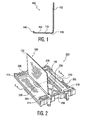
- a smart card heat sink 100 is shown as having a cross-sectional form that is substantially J-shaped. Substantially J-shaped is intended to include the embodiment in which the bottom portion of the J-shape is flat.
- the smart card heat sink 100 comprises a substantially vertical riser 102 extending up from one side of a contact plate 104 and an upturned hook 106 extending up from a side of the contact plate 104 opposite the vertical riser 102.
- the riser 102 extends upward from the contact plate 104 a greater distance than the hook 106 extends upward from the contact plate 104.
- the smart card heat sink 100 further comprises a contact face 108 that is the lower side of the contact plate 104 and a connection face 110 that is the upper side of the contact plate 104.
- the smart card heat sink 100 is generally formed of steel by bending a single sheet or plate of steel to form the cross-sectional shape illustrated in Figure 1 .
- the smart card heat sink may be substantially differently shaped and may be constructed, in part or in whole, of a material other than steel. Whatever material is chosen, the material should be suitable for thermal energy transfer.
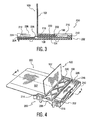
- a smart card socket 200 comprises a frame 202 shaped and sized to receive at least a portion of a conventional smart card (discussed infra and which generally is the size a typical credit card).
- the frame 202 comprises a base 204, a left sidewall 206 extending up from a left side of the base 204, a right sidewall 208 extending up from a right side of the base 204, and a rear wall 210 extending up from a rear side of the base 204.
- Smart card socket 200 further comprises a left forward alignment tab 212 extending from the left sidewall 206 toward the right sidewall 208 and a right forward alignment tab 214 extending from the right sidewall 208 toward the left sidewall 206. Further, smart card socket 200 comprises a left rear retention tab 216 extending from the left side of the rear wall 210 toward the front of the frame 202 and a right rear retention tab 218 extending from the right side of the rear wall 210 toward the front of the frame 202. Smart card socket 200 also comprises a crossbar 220 extending from the left sidewall 206 to the right sidewall 208.
- the innermost faces of the base 204, left sidewall 206, right sidewall 208, rear wall 210, and an underside 222 (shown in Figure 3 ) of crossbar 220 generally define a slot 224 for receiving a smart card into the frame 202 of the smart card socket 200.
- An underside of each left and right forward alignment tabs 212 and 214 also delimits the slot 224.
- left and right rear retention tabs 216 and 218 are biased to accept a smart card between each of the tabs 212 and 214 and the base 204.
- the tabs 212 and 214 are biased toward the base 204.
- resilient contacts 226 are carried by base 204 and protrude upward and out of base 204 into slot 224.
- FIGs 2 and 3 show smart card socket 200 without a smart card installed while Figures 4-6 show smart card socket 200 with a smart card 300 installed.
- Smart card 300 comprises a heat conductive face 302 that is generally thermally connected to heat generating components within the smart card 300 (not shown).
- the smart card heat sink 100 is assembled with smart card socket 200 by inserting contact plate 104 of smart card heat sink 100 into slot 224 so that connection face 110 of the contact plate 104 is substantially pressed against the underside 222 of crossbar 220.
- riser 102 is located forward of the contact plate 104 nearer the front of smart card socket 200.
- hook 106 is located rearward from the contact plate 104 nearer the rear wall 210.
- smart card heat sink 100 may be adhered, riveted, or otherwise fastened to frame 202.
- an adhesive agent may be disposed between connection face 110 and underside 222 of crossbar 220.
- a smart card heat sink may be formed integral to a frame of a smart card socket.
- the smart card 300 is inserted into the slot 224 of smart card socket 200 in an insertion direction from the front of the smart card socket 200 toward the rear wall 210. Specifically, smart card 300 is initially partially inserted into slot 224 and generally bounded by base 204, left sidewall 206, right sidewall 208, left forward alignment tab 212, and right forward alignment tab 214. Next, as smart card 300 is further advanced into the slot 224, heat conductive face 302 of smart card 300 contacts contact face 108 of contact plate 104. In this position, smart card 300 has forced protruding portions of resilient contacts 226 downward toward base 204.
- the contact plate 104 can be positioned or sandwiched between at least one wall of the smart card socket 200 and the smart card 300.
- One advantage of upward extending riser 102 is that as smart card 300 is inserted into slot 224, the riser 102 provides a natural interference with a portion of the smart card socket such as crossbar 200 and further prevents rearward movement of the smart card heat sink 100.
- the hook 106 while removing smart card 300 from slot 224, the hook 106 provides a naturally interference with a portion of the card socket such as crossbar 220 and further prevent forward movement of the smart card heat sink 100.
- the smart card 300 when smart card 300 is fully seated within the frame 202 of smart card socket 200, the smart card 300 generally abuts rear wall 210 and is releasably retained by left and right rear retention tabs 216 and 218 pressing downward on smart card 300 toward base 204. In this fmal position, substantially all of contact face 108 of smart card heat sink 100 is in thermal contact with heat conductive face 302 of smart card 300 and resilient contacts 226 are electrically connected to electrical contacts of the smart card 300 (not shown).
- frame 202 The structural components of frame 202 are sized and shaped so that, in this final position where smart card 300 is sandwiched between frame 202 and smart card heat sink 100, smart card 300 is firmly held between base 204 and contact face 108, ensuring a suitable thermal connection between heat conductive face 302 and contact face 108.
- this thermal connection allows transfer of heat energy from smart card 300 to smart card heat sink 100 and allows a reduction of smart card internal component (not shown) temperature of about 5°C or more.
- the reduction in temperature may be affected by increasing or decreasing the amount of surface area contact between the heat conductive face 302 and contact face 108, constructing the heat sink 100 of a different material, and increasing or decreasing the forces that press the smart card 300 to the smart card heat sink 100.
- the heat conductive face of the smart card may be differently located on the smart card.
- the heat conductive face may include the front, rear, lower, or side faces of the smart card, and a differently shaped heat sink may be provided for thermally contacting any one or combination of the faces of the smart card such thermally conductive face 302.
- the above-described operations illustrate a method of transferring heat energy away from a smart card.
- the method comprises associating a smart card heat sink with a smart card socket (optionally integrally) and sandwiching at least a portion of the smart card heat sink between at least a portion of a smart card and at least a portion of the smart card socket.
- at least a portion of the smart card heat sink is not positioned or sandwiched between the smart card and the smart card socket.
Landscapes
- Engineering & Computer Science (AREA)
- Artificial Intelligence (AREA)
- Computer Vision & Pattern Recognition (AREA)
- Physics & Mathematics (AREA)
- General Physics & Mathematics (AREA)
- Theoretical Computer Science (AREA)
- Cooling Or The Like Of Electrical Apparatus (AREA)
- Coupling Device And Connection With Printed Circuit (AREA)
Claims (5)
- Chipkartenhalterung (200) mit Kühlkörper, gekennzeichnet durch:einen Rahmen (202) mit einer Grundplatte (204), einer linken Seitenwand (206), einer rechten Seitenwand (208) und einer Querschiene (220), die einen Schlitz (224) definieren;einen Kühlkörper (100), der eine Kontaktplatte (104) enthält, die unter der Querschiene in dem Schlitz positioniert ist und für die Berührung mit einer wärmeleitenden Fläche einer Chipkarte (300) konfiguriert ist, wobei von der Kontaktplatte eine Stirnplatte (102) und ein Haken (106) einander gegenüberliegend nach oben verlaufen, wobei die Stirnplatte und der Haken die Bewegung des Kühlkörpers verhindern.
- Chipkartenhalterung nach Anspruch 1, dadurch gekennzeichnet, dass die Querschiene zwischen der linken Seitenwand und der rechten Seitenwand verläuft.
- Chipkartenhalterung nach Anspruch 1 oder 2, dadurch gekennzeichnet, dass die Kontaktplatte zwischen der Querschiene und der in den Schlitz eingeführten Chipkarte positioniert ist.
- Chipkartenhalterung nach Anspruch 1, 2 oder 3, dadurch gekennzeichnet, dass der Kühlkörper eine J-förmige Querschnittsform aufweist.
- Chipkartenhalterung nach Anspruch 1, 2, 3 oder 4, dadurch gekennzeichnet, dass die Stirnplatte über eine größere Strecke von der Kontaktplatte nach oben verläuft, als der Haken von der Kontaktplatte nach oben verläuft.
Applications Claiming Priority (2)
| Application Number | Priority Date | Filing Date | Title |
|---|---|---|---|
| US92768907P | 2007-05-04 | 2007-05-04 | |
| PCT/US2007/014461 WO2008136803A1 (en) | 2007-05-04 | 2007-06-20 | Smart card heat sink |
Publications (2)
| Publication Number | Publication Date |
|---|---|
| EP2145284A1 EP2145284A1 (de) | 2010-01-20 |
| EP2145284B1 true EP2145284B1 (de) | 2013-04-17 |
Family
ID=39110380
Family Applications (1)
| Application Number | Title | Priority Date | Filing Date |
|---|---|---|---|
| EP07796323.9A Not-in-force EP2145284B1 (de) | 2007-05-04 | 2007-06-20 | Chipkarten-kühlkörper |
Country Status (5)
| Country | Link |
|---|---|
| US (1) | US8172619B2 (de) |
| EP (1) | EP2145284B1 (de) |
| JP (1) | JP5227396B2 (de) |
| CN (1) | CN101663673B (de) |
| WO (1) | WO2008136803A1 (de) |
Families Citing this family (11)
| Publication number | Priority date | Publication date | Assignee | Title |
|---|---|---|---|---|
| CN102714928B (zh) | 2009-12-09 | 2015-11-25 | 汤姆森特许公司 | 具有微孔的机顶盒 |
| WO2011106082A1 (en) | 2010-02-25 | 2011-09-01 | Thomson Licensing | Miniature multilayer radiative cooling case with hidden quick release snaps |
| JP2013527615A (ja) | 2010-05-19 | 2013-06-27 | トムソン ライセンシング | 分散熱負荷を有するセットトップボックス |
| KR20140061299A (ko) | 2011-03-09 | 2014-05-21 | 톰슨 라이센싱 | 스냅-인 히트 싱크 및 스마트 카드 판독기를 갖는 셋톱 박스 또는 서버 |
| KR20140041701A (ko) | 2011-07-14 | 2014-04-04 | 톰슨 라이센싱 | 히트 싱크를 유지하기 위한 홀드다운 고정구를 갖는 스마트 카드 리더와 스냅인 히트 싱크를 구비한 셋톱박스 |
| US9390299B1 (en) * | 2015-02-25 | 2016-07-12 | Echostar Technologies L.L.C. | High data transfer smart card reader with heat sink |
| US9760742B2 (en) | 2015-06-26 | 2017-09-12 | Echostar Technologies L.L.C. | Dual purpose press-bar and heat sink for high data transfer integrated circuit card reader |
| JP6625004B2 (ja) | 2016-04-14 | 2019-12-25 | キヤノン株式会社 | カード型記録装置およびスロット装置 |
| US10043043B1 (en) * | 2017-02-07 | 2018-08-07 | DISH Technologies L.L.C. | Integrated circuit card reader with improved heat dissipation |
| US11792957B2 (en) * | 2021-08-10 | 2023-10-17 | Dell Products L.P. | System for cooling of computing components of an information handling system |
| CN115169371A (zh) * | 2022-08-15 | 2022-10-11 | 深圳市康睿优医疗器械有限公司 | 具有智能散热功能的读卡器 |
Family Cites Families (12)
| Publication number | Priority date | Publication date | Assignee | Title |
|---|---|---|---|---|
| JPS5783752U (de) * | 1980-11-07 | 1982-05-24 | ||
| FR2541018A1 (fr) | 1983-02-16 | 1984-08-17 | Radiotechnique Compelec | Procede de dissipation thermique, appareil de lecture-ecriture, et carte electronique a dissipation thermique elevee |
| JPH0363951U (de) * | 1989-10-25 | 1991-06-21 | ||
| TW387627U (en) * | 1996-11-30 | 2000-04-11 | Hon Hai Prec Ind Co Ltd | Electronic card connector |
| US5892216A (en) * | 1997-04-21 | 1999-04-06 | Airborn, Inc. | Smart card reader with electrostatic discharge protection |
| JPH118484A (ja) | 1997-06-16 | 1999-01-12 | Nec Corp | 電子機器の放熱構造 |
| TW324560U (en) * | 1997-06-25 | 1998-01-01 | Hon Hai Prec Ind Co Ltd | Connector shield device |
| US6109530A (en) * | 1998-07-08 | 2000-08-29 | Motorola, Inc. | Integrated circuit carrier package with battery coin cell |
| CN2354172Y (zh) * | 1998-09-18 | 1999-12-15 | 全人兴业有限公司 | 中央处理器散热片扣合装置 |
| JP3315969B2 (ja) * | 2000-05-09 | 2002-08-19 | 株式会社ソニー・コンピュータエンタテインメント | 電子機器 |
| JP4251452B2 (ja) * | 2002-03-06 | 2009-04-08 | タイコ・エレクトロニクス・コーポレイション | トランシーバモジュール組立体のイジェクタ機構 |
| JP3920256B2 (ja) * | 2003-10-02 | 2007-05-30 | 日本航空電子工業株式会社 | カード用コネクタ |
-
2007
- 2007-06-20 JP JP2010506164A patent/JP5227396B2/ja not_active Expired - Fee Related
- 2007-06-20 EP EP07796323.9A patent/EP2145284B1/de not_active Not-in-force
- 2007-06-20 CN CN200780052843.4A patent/CN101663673B/zh not_active Expired - Fee Related
- 2007-06-20 WO PCT/US2007/014461 patent/WO2008136803A1/en not_active Ceased
- 2007-06-20 US US12/450,411 patent/US8172619B2/en not_active Expired - Fee Related
Also Published As
| Publication number | Publication date |
|---|---|
| CN101663673A (zh) | 2010-03-03 |
| JP5227396B2 (ja) | 2013-07-03 |
| US20100073881A1 (en) | 2010-03-25 |
| JP2010526369A (ja) | 2010-07-29 |
| WO2008136803A1 (en) | 2008-11-13 |
| US8172619B2 (en) | 2012-05-08 |
| CN101663673B (zh) | 2016-09-07 |
| EP2145284A1 (de) | 2010-01-20 |
Similar Documents
| Publication | Publication Date | Title |
|---|---|---|
| US8172619B2 (en) | Smart card heat sink | |
| CN102084552B (zh) | 卡用连接器 | |
| US6890202B2 (en) | Connector for module | |
| CN205863535U (zh) | 卡缘连接器 | |
| CN107425316B (zh) | 基板边缘连接器 | |
| JP5727776B2 (ja) | 検出スイッチ構造及びそれを有するコネクタ | |
| JP5714313B2 (ja) | カード用コネクタ | |
| US9122899B2 (en) | Card connector with improved heat-dissipation, retention, and ESD protection features | |
| CN103004295A (zh) | 散热卡连接器 | |
| US9431743B2 (en) | Connector | |
| US6629860B1 (en) | Electrical card connector with an improved shell | |
| US20100068903A1 (en) | Electrical connector | |
| CN107422804B (zh) | 主机板组件 | |
| JP2009272098A (ja) | カード用コネクタ | |
| US8755193B2 (en) | Method and system for providing a customized storage container | |
| US20100243203A1 (en) | Cooling device for add-on card | |
| US7247055B2 (en) | Card connector | |
| US20060110967A1 (en) | Land grid array connector without undesired engagement | |
| CN213520447U (zh) | 卡托盘 | |
| JP6319760B2 (ja) | カードコネクタ | |
| JP6211167B2 (ja) | 基板エッジコネクタ | |
| CN201868605U (zh) | 卡连接器 | |
| CN202434788U (zh) | 电连接器 | |
| JP6040475B2 (ja) | 基板エッジコネクタ | |
| CN112310725A (zh) | 卡托盘 |
Legal Events
| Date | Code | Title | Description |
|---|---|---|---|
| PUAI | Public reference made under article 153(3) epc to a published international application that has entered the european phase |
Free format text: ORIGINAL CODE: 0009012 |
|
| 17P | Request for examination filed |
Effective date: 20091118 |
|
| AK | Designated contracting states |
Kind code of ref document: A1 Designated state(s): AT BE BG CH CY CZ DE DK EE ES FI FR GB GR HU IE IS IT LI LT LU LV MC MT NL PL PT RO SE SI SK TR |
|
| AX | Request for extension of the european patent |
Extension state: AL BA HR MK RS |
|
| RAP1 | Party data changed (applicant data changed or rights of an application transferred) |
Owner name: THOMSON LICENSING |
|
| DAX | Request for extension of the european patent (deleted) | ||
| 17Q | First examination report despatched |
Effective date: 20120503 |
|
| GRAP | Despatch of communication of intention to grant a patent |
Free format text: ORIGINAL CODE: EPIDOSNIGR1 |
|
| GRAS | Grant fee paid |
Free format text: ORIGINAL CODE: EPIDOSNIGR3 |
|
| GRAA | (expected) grant |
Free format text: ORIGINAL CODE: 0009210 |
|
| AK | Designated contracting states |
Kind code of ref document: B1 Designated state(s): AT BE BG CH CY CZ DE DK EE ES FI FR GB GR HU IE IS IT LI LT LU LV MC MT NL PL PT RO SE SI SK TR |
|
| REG | Reference to a national code |
Ref country code: GB Ref legal event code: FG4D |
|
| REG | Reference to a national code |
Ref country code: CH Ref legal event code: EP |
|
| REG | Reference to a national code |
Ref country code: IE Ref legal event code: FG4D |
|
| REG | Reference to a national code |
Ref country code: AT Ref legal event code: REF Ref document number: 607693 Country of ref document: AT Kind code of ref document: T Effective date: 20130515 Ref country code: GB Ref legal event code: 746 Effective date: 20130423 |
|
| REG | Reference to a national code |
Ref country code: DE Ref legal event code: R096 Ref document number: 602007029849 Country of ref document: DE Effective date: 20130613 |
|
| REG | Reference to a national code |
Ref country code: DE Ref legal event code: R084 Ref document number: 602007029849 Country of ref document: DE Effective date: 20130419 |
|
| REG | Reference to a national code |
Ref country code: AT Ref legal event code: MK05 Ref document number: 607693 Country of ref document: AT Kind code of ref document: T Effective date: 20130417 |
|
| REG | Reference to a national code |
Ref country code: LT Ref legal event code: MG4D |
|
| REG | Reference to a national code |
Ref country code: NL Ref legal event code: VDEP Effective date: 20130417 |
|
| PG25 | Lapsed in a contracting state [announced via postgrant information from national office to epo] |
Ref country code: SE Free format text: LAPSE BECAUSE OF FAILURE TO SUBMIT A TRANSLATION OF THE DESCRIPTION OR TO PAY THE FEE WITHIN THE PRESCRIBED TIME-LIMIT Effective date: 20130417 Ref country code: SI Free format text: LAPSE BECAUSE OF FAILURE TO SUBMIT A TRANSLATION OF THE DESCRIPTION OR TO PAY THE FEE WITHIN THE PRESCRIBED TIME-LIMIT Effective date: 20130417 Ref country code: PT Free format text: LAPSE BECAUSE OF FAILURE TO SUBMIT A TRANSLATION OF THE DESCRIPTION OR TO PAY THE FEE WITHIN THE PRESCRIBED TIME-LIMIT Effective date: 20130819 Ref country code: FI Free format text: LAPSE BECAUSE OF FAILURE TO SUBMIT A TRANSLATION OF THE DESCRIPTION OR TO PAY THE FEE WITHIN THE PRESCRIBED TIME-LIMIT Effective date: 20130417 Ref country code: BE Free format text: LAPSE BECAUSE OF FAILURE TO SUBMIT A TRANSLATION OF THE DESCRIPTION OR TO PAY THE FEE WITHIN THE PRESCRIBED TIME-LIMIT Effective date: 20130417 Ref country code: IS Free format text: LAPSE BECAUSE OF FAILURE TO SUBMIT A TRANSLATION OF THE DESCRIPTION OR TO PAY THE FEE WITHIN THE PRESCRIBED TIME-LIMIT Effective date: 20130817 Ref country code: ES Free format text: LAPSE BECAUSE OF FAILURE TO SUBMIT A TRANSLATION OF THE DESCRIPTION OR TO PAY THE FEE WITHIN THE PRESCRIBED TIME-LIMIT Effective date: 20130728 Ref country code: LT Free format text: LAPSE BECAUSE OF FAILURE TO SUBMIT A TRANSLATION OF THE DESCRIPTION OR TO PAY THE FEE WITHIN THE PRESCRIBED TIME-LIMIT Effective date: 20130417 Ref country code: AT Free format text: LAPSE BECAUSE OF FAILURE TO SUBMIT A TRANSLATION OF THE DESCRIPTION OR TO PAY THE FEE WITHIN THE PRESCRIBED TIME-LIMIT Effective date: 20130417 Ref country code: GR Free format text: LAPSE BECAUSE OF FAILURE TO SUBMIT A TRANSLATION OF THE DESCRIPTION OR TO PAY THE FEE WITHIN THE PRESCRIBED TIME-LIMIT Effective date: 20130718 |
|
| PG25 | Lapsed in a contracting state [announced via postgrant information from national office to epo] |
Ref country code: LV Free format text: LAPSE BECAUSE OF FAILURE TO SUBMIT A TRANSLATION OF THE DESCRIPTION OR TO PAY THE FEE WITHIN THE PRESCRIBED TIME-LIMIT Effective date: 20130417 Ref country code: BG Free format text: LAPSE BECAUSE OF FAILURE TO SUBMIT A TRANSLATION OF THE DESCRIPTION OR TO PAY THE FEE WITHIN THE PRESCRIBED TIME-LIMIT Effective date: 20130717 Ref country code: PL Free format text: LAPSE BECAUSE OF FAILURE TO SUBMIT A TRANSLATION OF THE DESCRIPTION OR TO PAY THE FEE WITHIN THE PRESCRIBED TIME-LIMIT Effective date: 20130417 Ref country code: CY Free format text: LAPSE BECAUSE OF FAILURE TO SUBMIT A TRANSLATION OF THE DESCRIPTION OR TO PAY THE FEE WITHIN THE PRESCRIBED TIME-LIMIT Effective date: 20130417 |
|
| PG25 | Lapsed in a contracting state [announced via postgrant information from national office to epo] |
Ref country code: SK Free format text: LAPSE BECAUSE OF FAILURE TO SUBMIT A TRANSLATION OF THE DESCRIPTION OR TO PAY THE FEE WITHIN THE PRESCRIBED TIME-LIMIT Effective date: 20130417 Ref country code: CZ Free format text: LAPSE BECAUSE OF FAILURE TO SUBMIT A TRANSLATION OF THE DESCRIPTION OR TO PAY THE FEE WITHIN THE PRESCRIBED TIME-LIMIT Effective date: 20130417 Ref country code: EE Free format text: LAPSE BECAUSE OF FAILURE TO SUBMIT A TRANSLATION OF THE DESCRIPTION OR TO PAY THE FEE WITHIN THE PRESCRIBED TIME-LIMIT Effective date: 20130417 Ref country code: MC Free format text: LAPSE BECAUSE OF FAILURE TO SUBMIT A TRANSLATION OF THE DESCRIPTION OR TO PAY THE FEE WITHIN THE PRESCRIBED TIME-LIMIT Effective date: 20130417 Ref country code: DK Free format text: LAPSE BECAUSE OF FAILURE TO SUBMIT A TRANSLATION OF THE DESCRIPTION OR TO PAY THE FEE WITHIN THE PRESCRIBED TIME-LIMIT Effective date: 20130417 |
|
| REG | Reference to a national code |
Ref country code: CH Ref legal event code: PL |
|
| PLBE | No opposition filed within time limit |
Free format text: ORIGINAL CODE: 0009261 |
|
| STAA | Information on the status of an ep patent application or granted ep patent |
Free format text: STATUS: NO OPPOSITION FILED WITHIN TIME LIMIT |
|
| PG25 | Lapsed in a contracting state [announced via postgrant information from national office to epo] |
Ref country code: IT Free format text: LAPSE BECAUSE OF FAILURE TO SUBMIT A TRANSLATION OF THE DESCRIPTION OR TO PAY THE FEE WITHIN THE PRESCRIBED TIME-LIMIT Effective date: 20130417 Ref country code: RO Free format text: LAPSE BECAUSE OF FAILURE TO SUBMIT A TRANSLATION OF THE DESCRIPTION OR TO PAY THE FEE WITHIN THE PRESCRIBED TIME-LIMIT Effective date: 20130417 Ref country code: NL Free format text: LAPSE BECAUSE OF FAILURE TO SUBMIT A TRANSLATION OF THE DESCRIPTION OR TO PAY THE FEE WITHIN THE PRESCRIBED TIME-LIMIT Effective date: 20130417 |
|
| 26N | No opposition filed |
Effective date: 20140120 |
|
| REG | Reference to a national code |
Ref country code: IE Ref legal event code: MM4A |
|
| PG25 | Lapsed in a contracting state [announced via postgrant information from national office to epo] |
Ref country code: LI Free format text: LAPSE BECAUSE OF NON-PAYMENT OF DUE FEES Effective date: 20130630 Ref country code: CH Free format text: LAPSE BECAUSE OF NON-PAYMENT OF DUE FEES Effective date: 20130630 Ref country code: IE Free format text: LAPSE BECAUSE OF NON-PAYMENT OF DUE FEES Effective date: 20130620 |
|
| REG | Reference to a national code |
Ref country code: DE Ref legal event code: R097 Ref document number: 602007029849 Country of ref document: DE Effective date: 20140120 |
|
| PG25 | Lapsed in a contracting state [announced via postgrant information from national office to epo] |
Ref country code: MT Free format text: LAPSE BECAUSE OF FAILURE TO SUBMIT A TRANSLATION OF THE DESCRIPTION OR TO PAY THE FEE WITHIN THE PRESCRIBED TIME-LIMIT Effective date: 20130417 |
|
| PG25 | Lapsed in a contracting state [announced via postgrant information from national office to epo] |
Ref country code: TR Free format text: LAPSE BECAUSE OF FAILURE TO SUBMIT A TRANSLATION OF THE DESCRIPTION OR TO PAY THE FEE WITHIN THE PRESCRIBED TIME-LIMIT Effective date: 20130417 |
|
| PG25 | Lapsed in a contracting state [announced via postgrant information from national office to epo] |
Ref country code: LU Free format text: LAPSE BECAUSE OF NON-PAYMENT OF DUE FEES Effective date: 20130620 Ref country code: HU Free format text: LAPSE BECAUSE OF FAILURE TO SUBMIT A TRANSLATION OF THE DESCRIPTION OR TO PAY THE FEE WITHIN THE PRESCRIBED TIME-LIMIT; INVALID AB INITIO Effective date: 20070620 |
|
| REG | Reference to a national code |
Ref country code: FR Ref legal event code: PLFP Year of fee payment: 10 |
|
| REG | Reference to a national code |
Ref country code: FR Ref legal event code: PLFP Year of fee payment: 11 |
|
| REG | Reference to a national code |
Ref country code: DE Ref legal event code: R082 Ref document number: 602007029849 Country of ref document: DE Representative=s name: DEHNS, DE Ref country code: DE Ref legal event code: R082 Ref document number: 602007029849 Country of ref document: DE Representative=s name: DEHNS PATENT AND TRADEMARK ATTORNEYS, DE Ref country code: DE Ref legal event code: R082 Ref document number: 602007029849 Country of ref document: DE Representative=s name: HOFSTETTER, SCHURACK & PARTNER PATENT- UND REC, DE |
|
| REG | Reference to a national code |
Ref country code: FR Ref legal event code: PLFP Year of fee payment: 12 |
|
| REG | Reference to a national code |
Ref country code: DE Ref legal event code: R082 Ref document number: 602007029849 Country of ref document: DE Representative=s name: DEHNS, DE Ref country code: DE Ref legal event code: R081 Ref document number: 602007029849 Country of ref document: DE Owner name: INTERDIGITAL CE PATENT HOLDINGS SAS, FR Free format text: FORMER OWNER: THOMSON LICENSING, ISSY-LES-MOULINEAUX, FR Ref country code: DE Ref legal event code: R082 Ref document number: 602007029849 Country of ref document: DE Representative=s name: DEHNS PATENT AND TRADEMARK ATTORNEYS, DE |
|
| REG | Reference to a national code |
Ref country code: GB Ref legal event code: 732E Free format text: REGISTERED BETWEEN 20190926 AND 20191002 |
|
| PGFP | Annual fee paid to national office [announced via postgrant information from national office to epo] |
Ref country code: FR Payment date: 20200626 Year of fee payment: 14 |
|
| PGFP | Annual fee paid to national office [announced via postgrant information from national office to epo] |
Ref country code: GB Payment date: 20200630 Year of fee payment: 14 |
|
| PGFP | Annual fee paid to national office [announced via postgrant information from national office to epo] |
Ref country code: DE Payment date: 20200630 Year of fee payment: 14 |
|
| REG | Reference to a national code |
Ref country code: DE Ref legal event code: R119 Ref document number: 602007029849 Country of ref document: DE |
|
| GBPC | Gb: european patent ceased through non-payment of renewal fee |
Effective date: 20210620 |
|
| PG25 | Lapsed in a contracting state [announced via postgrant information from national office to epo] |
Ref country code: GB Free format text: LAPSE BECAUSE OF NON-PAYMENT OF DUE FEES Effective date: 20210620 Ref country code: DE Free format text: LAPSE BECAUSE OF NON-PAYMENT OF DUE FEES Effective date: 20220101 |
|
| PG25 | Lapsed in a contracting state [announced via postgrant information from national office to epo] |
Ref country code: FR Free format text: LAPSE BECAUSE OF NON-PAYMENT OF DUE FEES Effective date: 20210630 |