EP2143998B1 - Brennereinheit für staubförmigen Festbrennstoff - Google Patents
Brennereinheit für staubförmigen Festbrennstoff Download PDFInfo
- Publication number
- EP2143998B1 EP2143998B1 EP09165089A EP09165089A EP2143998B1 EP 2143998 B1 EP2143998 B1 EP 2143998B1 EP 09165089 A EP09165089 A EP 09165089A EP 09165089 A EP09165089 A EP 09165089A EP 2143998 B1 EP2143998 B1 EP 2143998B1
- Authority
- EP
- European Patent Office
- Prior art keywords
- tube
- combustion
- burner
- solid fuel
- unit according
- Prior art date
- Legal status (The legal status is an assumption and is not a legal conclusion. Google has not performed a legal analysis and makes no representation as to the accuracy of the status listed.)
- Active
Links
- 239000000446 fuel Substances 0.000 title description 20
- 238000002485 combustion reaction Methods 0.000 claims description 84
- 239000004449 solid propellant Substances 0.000 claims description 38
- 239000007789 gas Substances 0.000 claims description 19
- 235000019738 Limestone Nutrition 0.000 claims description 9
- 239000006028 limestone Substances 0.000 claims description 9
- 239000000203 mixture Substances 0.000 description 6
- 239000000428 dust Substances 0.000 description 5
- ATUOYWHBWRKTHZ-UHFFFAOYSA-N Propane Chemical compound CCC ATUOYWHBWRKTHZ-UHFFFAOYSA-N 0.000 description 4
- 239000002006 petroleum coke Substances 0.000 description 4
- 230000000712 assembly Effects 0.000 description 3
- 238000000429 assembly Methods 0.000 description 3
- 238000010276 construction Methods 0.000 description 3
- 238000002347 injection Methods 0.000 description 3
- 239000007924 injection Substances 0.000 description 3
- 206010006784 Burning sensation Diseases 0.000 description 2
- 238000007664 blowing Methods 0.000 description 2
- 239000001294 propane Substances 0.000 description 2
- 230000003134 recirculating effect Effects 0.000 description 2
- 230000015572 biosynthetic process Effects 0.000 description 1
- 238000004140 cleaning Methods 0.000 description 1
- 238000001816 cooling Methods 0.000 description 1
- 238000010304 firing Methods 0.000 description 1
- 239000008187 granular material Substances 0.000 description 1
- 230000005484 gravity Effects 0.000 description 1
- 230000010354 integration Effects 0.000 description 1
- 230000007774 longterm Effects 0.000 description 1
- 238000012423 maintenance Methods 0.000 description 1
- 239000000463 material Substances 0.000 description 1
- 230000005855 radiation Effects 0.000 description 1
- 230000001846 repelling effect Effects 0.000 description 1
- 230000000630 rising effect Effects 0.000 description 1
- 238000000926 separation method Methods 0.000 description 1
Images


Classifications
-
- F—MECHANICAL ENGINEERING; LIGHTING; HEATING; WEAPONS; BLASTING
- F23—COMBUSTION APPARATUS; COMBUSTION PROCESSES
- F23D—BURNERS
- F23D1/00—Burners for combustion of pulverulent fuel
- F23D1/02—Vortex burners, e.g. for cyclone-type combustion apparatus
-
- F—MECHANICAL ENGINEERING; LIGHTING; HEATING; WEAPONS; BLASTING
- F27—FURNACES; KILNS; OVENS; RETORTS
- F27B—FURNACES, KILNS, OVENS, OR RETORTS IN GENERAL; OPEN SINTERING OR LIKE APPARATUS
- F27B1/00—Shaft or like vertical or substantially vertical furnaces
- F27B1/005—Shaft or like vertical or substantially vertical furnaces wherein no smelting of the charge occurs, e.g. calcining or sintering furnaces
-
- F—MECHANICAL ENGINEERING; LIGHTING; HEATING; WEAPONS; BLASTING
- F27—FURNACES; KILNS; OVENS; RETORTS
- F27B—FURNACES, KILNS, OVENS, OR RETORTS IN GENERAL; OPEN SINTERING OR LIKE APPARATUS
- F27B1/00—Shaft or like vertical or substantially vertical furnaces
- F27B1/10—Details, accessories, or equipment peculiar to furnaces of these types
- F27B1/16—Arrangements of tuyeres
-
- F—MECHANICAL ENGINEERING; LIGHTING; HEATING; WEAPONS; BLASTING
- F27—FURNACES; KILNS; OVENS; RETORTS
- F27D—DETAILS OR ACCESSORIES OF FURNACES, KILNS, OVENS, OR RETORTS, IN SO FAR AS THEY ARE OF KINDS OCCURRING IN MORE THAN ONE KIND OF FURNACE
- F27D99/00—Subject matter not provided for in other groups of this subclass
- F27D99/0001—Heating elements or systems
- F27D99/0033—Heating elements or systems using burners
-
- F—MECHANICAL ENGINEERING; LIGHTING; HEATING; WEAPONS; BLASTING
- F23—COMBUSTION APPARATUS; COMBUSTION PROCESSES
- F23C—METHODS OR APPARATUS FOR COMBUSTION USING FLUID FUEL OR SOLID FUEL SUSPENDED IN A CARRIER GAS OR AIR
- F23C2900/00—Special features of, or arrangements for combustion apparatus using fluid fuels or solid fuels suspended in air; Combustion processes therefor
- F23C2900/03006—Reverse flow combustion chambers
-
- F—MECHANICAL ENGINEERING; LIGHTING; HEATING; WEAPONS; BLASTING
- F23—COMBUSTION APPARATUS; COMBUSTION PROCESSES
- F23C—METHODS OR APPARATUS FOR COMBUSTION USING FLUID FUEL OR SOLID FUEL SUSPENDED IN A CARRIER GAS OR AIR
- F23C2900/00—Special features of, or arrangements for combustion apparatus using fluid fuels or solid fuels suspended in air; Combustion processes therefor
- F23C2900/99004—Combustion process using petroleum coke or any other fuel with a very low content in volatile matters
-
- F—MECHANICAL ENGINEERING; LIGHTING; HEATING; WEAPONS; BLASTING
- F23—COMBUSTION APPARATUS; COMBUSTION PROCESSES
- F23D—BURNERS
- F23D2201/00—Burners adapted for particulate solid or pulverulent fuels
- F23D2201/20—Fuel flow guiding devices
-
- F—MECHANICAL ENGINEERING; LIGHTING; HEATING; WEAPONS; BLASTING
- F23—COMBUSTION APPARATUS; COMBUSTION PROCESSES
- F23D—BURNERS
- F23D2201/00—Burners adapted for particulate solid or pulverulent fuels
- F23D2201/30—Wear protection
-
- F—MECHANICAL ENGINEERING; LIGHTING; HEATING; WEAPONS; BLASTING
- F23—COMBUSTION APPARATUS; COMBUSTION PROCESSES
- F23D—BURNERS
- F23D2900/00—Special features of, or arrangements for burners using fluid fuels or solid fuels suspended in a carrier gas
- F23D2900/00016—Preventing or reducing deposit build-up on burner parts, e.g. from carbon
Definitions
- the invention relates to a burner unit for dusty solid fuel having a first tube for conveying the solid fuel in a first conveying direction, wherein a deflecting body for deflecting the emerging from the first tube solid fuel jet is arranged in extension of the first tube. Furthermore, the invention relates to a burner assembly for a furnace, in particular for a ring-shaft furnace for burning limestone.
- Burner units of the type mentioned are known from the prior art. They are preferably used in shaft furnace systems, for example in annular shaft furnaces for burning limestone.
- the particular procedural challenge is to achieve the fullest possible implementation of the dusty fuel - this can be, for example, petroleum coke dust - in hot gases in order to use the energy content of the dusty solid fuel as completely as possible.
- the deflected fuel stream then mixes with another oncoming air stream, so that an approximately complete mixing of rod-shaped solid fuel and combustion air and thus a complete combustion of the fuel is ensured.
- a deflecting body in extension of the transport tube for the fuel-air mixture is for example from the DE 10 2006 035 174 A1and the FR 2 842 584 A1 known.
- a mixture of petroleum coke dust and primary air is deflected after exiting the burner lance at a cross-sectionally C-shaped flow deflector and mixed with tangentially injected into the burner chamber secondary air, wherein the thereby adjusting mixture of tangential blowing verdrallter secondary air, petcoke dust and primary air is transported in the direction of the exit of the combustion chamber, whereby it is completely converted into hot gases.
- the present invention is therefore based on the object to provide a burner unit for dusty solid fuel of the type mentioned, the complete implementation of the dusty fuel in hot gases ensures. Furthermore, the burner unit should be able to be operated with reduced maintenance costs, for example, by constructively avoiding the known from the prior art problem of buildup of the deflected dust-like fuel.
- the task is solved with a burner unit for dust-like solid fuel according to the preamble of claim 1, characterized in that the first tube surrounding the first tube baffle body, which deflects the deflected by the deflecting solid fuel jet substantially in the first conveying direction again.
- the particular advantage of the burner unit according to the invention is that on the one hand the principle of the deflection of the fuel jet can be maintained, which has proven to be extremely effective with respect to an intensive mixing of the dust-like fuel with the combustion air. On the other hand, it is ensured by the use of the impact tube surrounding the first tube, that the fuel jet undergoes the desired renewed change of direction, but without the risk that parts of the fuel jet strikes back into the burner unit and settle there, which is associated with the known problem.
- the baffle body can assume all geometric shapes which ensure that the solid fuel jet initially deflected by the deflecting body is deflected again in the first conveying direction, without the overall aerodynamics of the construction being changed significantly overall, particularly when installed in a corresponding burner housing.
- first tube with a circular cross-section of the baffle body is preferably annular.
- the first tube is coaxially surrounded by at least one second tube to form an annular channel for conveying combustion air, wherein the free end of the second tube is set back axially relative to the free end of the first tube, wherein the impact body to is arranged opposite the free end of the second tube projecting pipe section of the first tube.
- This arrangement creates a combustion air cone surrounding the fuel jet emerging from the first tube, which on the one hand initially permits spatial separation of the solid fuel jet from the lining surrounding the combustion chamber in which the burner unit is arranged, wherein in the further course intensive mixing takes place second tube exiting combustion air with the solid fuel jet, which is a prerequisite for a complete implementation of the dusty solid fuel in hot gases takes place.
- the combustion air can be introduced, for example, via a substantially radial feed line into the second tube.
- a combustion chamber is provided in the flow direction in front of the second tube, in which a gas-operated pilot burner is arranged.
- a gas-operated pilot burner is arranged.
- additional thermal energy which is necessary to enable ignition of the pulverulent solid fuel entering a combustion chamber, can be provided during start-up of the furnace-fired furnace.
- the combustion chamber, in which the pilot burner is arranged this can be fed through a line opening into the combustion chamber primary combustion air, wherein in the conduit a throttle valve is arranged to the combustion of the gas also supplied, for example propane, and thus indirectly the temperature of dust-like solid fuel to be able to control exactly.
- the pilot burner can be switched off since the flame itself as well as the heat radiation of the refractory furnace lining provide enough thermal energy for stable burner operation.
- the exhaust gases of the pilot burner are preferably derived from the second tube surrounding the first tube from the combustion chamber. Accordingly, the combustion chamber is connected according to a further embodiment of the invention with the second tube, so that the burner gases into the second tube can be initiated and exit from this together with the combustion air in a combustion chamber.
- Another aspect of the present invention relates to a burner assembly for an oven, in particular for a ring-shaft furnace for burning limestone, with a combustion chamber defining a burner housing and a burner unit according to one of claims 1 to 7.
- a powerful and efficiently operating burner assembly is provided which ensures trouble-free continuous operation in an oven, in particular in a ring-shaft furnace for burning limestone.
- the combustion chamber of the burner assembly can assume a wide variety of geometries. However, it is preferably substantially cylindrical, wherein the burner unit is arranged substantially coaxially in the combustion chamber.
- the burner housing comprises a screw housing into which a combustion air duct opens tangentially.
- a combustion air duct opens tangentially.
- the screw housing is arranged back in the propagation direction of the burner flame relative to the free end of the first tube of the burner unit.
- a burner arrangement known from the prior art is shown.
- the burner assembly comprises a burner housing 100 with a rotationally symmetrical combustion chamber 200, which initially widens conically in the transport direction of the fuel or in the direction of propagation of the flame and then tapers conically in the form of a nozzle up to the burner exit.
- a coaxial with the combustion chamber 200 arranged central tube 300 dust-like solid fuel is pneumatically conveyed and exits at the free end 300 a of the central tube 300 from this. Subsequently, the dust-like solid fuel strikes a flow deflector 400, through which the fuel jet is deflected substantially 180 ° from its original flow direction.
- the secondary combustion air blown into the combustion space 200 at its closed end via a feed 500 arranged tangentially to the combustion chamber 200 is twisted in the combustion chamber 200, as indicated by the spiral line S.
- the twisted secondary combustion air then mixes with the recirculated fuel jet, with a targeted mixing takes place, so that a strong air-enriched amount of dust flows through the burner chamber 200 in the direction of its output and passes into the burner flame B.
- tertiary combustion air is still stepped through several tangentially arranged nozzles introduced into the combustion chamber 200 to support the swirl flow in the combustion chamber 200.
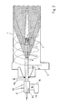
- FIG. 2 In contrast, an improved burner arrangement X is shown, which can be used, for example, in a ring-shaft furnace for burning limestone.
- the burner assembly X in turn comprises a housing 1 which encloses a presently cylindrical combustion chamber 2.
- a first tube 3 In the cylindrical combustion chamber 2 extends substantially coaxially a first tube 3 for the promotion of a dust-like solid fuel, in this case petcoke dust.
- a deflecting 4 for deflecting the Arranged from the first tube 3 solid fuel jet, which in the present case has approximately the shape of a mirrored "E".
- Other geometrical shapes of the deflecting body are also conceivable, for example those of a mirrored "C" or the like.
- the first tube 3 is in the burner assembly of Fig. 2 Coaxially surrounded by a second tube 6 over a certain length.
- combustion air so-called secondary air, can be conducted, which is supplied to the pipe via a radial supply line 6b.
- a present annular baffle body 7 is arranged in relative proximity to the deflection body 4, whose function will be explained in more detail below.
- the burner assembly X of Fig. 2 further comprises a arranged in the flow direction of the fuel in front of the burner housing combustion chamber 8, in which a pilot burner 8a is arranged for gaseous fuel, such as propane gas. Accordingly, supply lines 8b are provided for the supply of gaseous fuel as well as a combustion air supply line 8c, in which the volume flow can be adjusted by means of a throttle flap 8c *.
- a pilot burner 8a is arranged for gaseous fuel, such as propane gas.
- supply lines 8b are provided for the supply of gaseous fuel as well as a combustion air supply line 8c, in which the volume flow can be adjusted by means of a throttle flap 8c *.
- the combustion chamber 8 is connected to the second tube 6 at the end such that the exhaust gases of the pilot burner 8a can flow directly into the annular channel of the second tube and so with the introduced via the feed line 6b in the second pipe combustion air flow into the combustion chamber 2.
- a screw housing 5 is arranged, via which a mixture of combustion air and recirculating exhaust gas can be introduced tangentially with a very high volume flow.
- a mixture of the dust-like solid fuel and a transport air flow is introduced via its rear end and conveyed through the first tube 3 into the combustion chamber 2.
- the dust-like solid fuel then exits at the free end of the tube 3 and bounces against the deflection body 4, whereby it is deflected by approximately 180 ° in the opposite direction.
- the thus deflected fuel jet is now on the baffle 7, which is arranged on the opposite to the second pipe 6 projecting pipe section of the first tube 3, again deflected, so that it flows substantially back in the original conveying direction, but it has a highly divergent flow profile ,
- the gas ignition burner 8a arranged in the combustion chamber 8 becomes additional operated to provide the necessary for the ignition of the solid fuel thermal energy.
- the hot gases of the pilot burner 8a then flow together with the combustion air into the combustion chamber 2.
- the pilot burner 8a can be switched off again.
- the volume flow of the combustion air emerging from the second tube is only a fraction of the injection air flowing in tangentially via the screw housing 5, which consists of a mixture of preheated blowing air and recirculating kiln exhaust gas, as in connection with FIG Fig. 3 will be explained in more detail.
- the injection air enters the combustion chamber 2 in a highly twisted manner, as indicated by the spiral line D.
- a burner assembly in a ring shaft furnace for burning limestone is in the Fig. 3 shown.
- the ring shaft furnace of Fig. 3 is constructed according to the type "Beckenbach” and shall be briefly described below for the purpose of understanding the principle.
- the oven has a cylindrical outer shell, which is divided into a top shaft 20 and a main shaft 10.
- the inner shaft wall of the main shaft 10 is formed by a lower inner cylinder 30, the upper shaft 20 by an upper inner cylinder 40.
- the combustion zone BZ are a plurality of burner assemblies X associated with Fig. 2 described type arranged in a lower burner level, one of which is visible in the present sectional drawing.
- the granular material G to be fired is introduced into the annular shaft furnace and, due to gravity, initially moves through the preheating zone VZ, where it is heated in countercurrent by exhaust gases rising from the combustion zone BZ.
- the firing material G has passed the upper inner cylinder 40, it enters the combustion zone BZ and is first burned there in countercurrent and below the lower burner plane in direct current.
- the now fired Good G * enters the cooling zone KZ, where it is again cooled in countercurrent.
- the good G * is discharged from the ring shaft furnace.
- a partial exhaust gas flow into the upper inner cylinder 40 and from there into a recuperator unit 70, where it heats a motive air flow.
- injectors 50 together with a partial exhaust gas stream, which in turn flows through the lower inner cylinder 30 and one in the injectors 50.
Landscapes
- Engineering & Computer Science (AREA)
- Mechanical Engineering (AREA)
- General Engineering & Computer Science (AREA)
- Chemical & Material Sciences (AREA)
- Combustion & Propulsion (AREA)
Description
- Die Erfindung betrifft eine Brennereinheit für staubförmigen Festbrennstoff mit einem ersten Rohr zur Förderung des Festbrennstoffes in einer ersten Förderrichtung, wobei in Verlängerung des ersten Rohrs ein Umlenkkörper zur Umlenkung des aus dem ersten Rohr austretenden Festbrennstoffstrahls angeordnet ist. Ferner betrifft die Erfindung eine Brenneranordnung für einen Ofen, insbesondere für einen Ringschachtofen zum Brennen von Kalkstein.
- Brennereinheiten der eingangs genannten Art sind aus dem Stand der Technik bekannt. Bevorzugt werden sie in Schachtofenanlagen, beispielsweise in Ringschachtöfen zum Brennen von Kalkstein, eingesetzt. Hierbei besteht die besondere verfahrenstechnische Herausforderung darin, eine möglichst vollständige Umsetzung des staubförmigen Brennstoffes - hierbei kann es sich beispielsweise um Petrolkoksstaub handeln - in Heißgase zu erreichen, um den Energiegehalt des staubförmigen Festbrennstoffs möglichst vollständig nutzen zu können.
- Aus dem Stand der Technik ist ferner bekannt, den pneumatisch, d.h. in einem Luftstrom, durch das erste Rohr transportierten staubförmigen Festbrennstoff durch einen in Verlängerung des Rohres angeordneten Umlenkkörper in eine im Wesentlichen entgegengesetzte Richtung zum Brennereingang hin umzulenken. Der umgelenkte Brennstoffstrom vermischt sich sodann mit einem weiteren entgegenkommenden Luftstrom, so dass eine annähernd vollständige Durchmischung von stabförmigem Festbrennstoff und Verbrennungsluft und damit eine vollständige Verbrennung des Brennstoffs sichergestellt wird. Ein solcher mit einem Umlenkkörper in Verlängerung des Transportrohres für das Brennstoff-Luftgemisch ist beispielsweise aus der
DE 10 2006 035 174 A1und derFR 2 842 584 A1 - Aus der Praxis ist eine weitere Brennerkonstruktion bekannt, bei der das erste Rohr zur Förderung des Festbrennstoffes von einem zweiten koaxial angeordneten Rohr umgeben ist, durch welches Sekundärluft parallel zum Brennstoff transportiert wird, die sich beim Auftreffen auf den durch den Umlenkkörper umgelenkten Festbrennstoffstrahl mit diesem intensiv vermischt. Insbesondere bei dieser Brennerkonstruktion hat sich in der Praxis gezeigt, dass der von dem Umlenkkörper zurückgelenkte Festbrennstoffstrahl vielfach in das umgebene Rohr zurückschlägt und dort zu Ablagerungen führt, die langfristig zu einem Verschluss dieses Rohrs führen.
- Der vorliegenden Erfindung liegt daher die Aufgabe zugrunde, eine Brennereinheit für staubförmigen Festbrennstoff der eingangs genannten Art bereitzustellen, die die vollständige Umsetzung des staubförmigen Brennstoffes in Heißgase sicherstellt. Ferner soll die Brennereinheit mit reduzierten Wartungskosten betrieben werden können, indem beispielsweise das aus dem Stand der Technik bekannte Problem der Ansatzbildung des zurückgelenkten staubförmigen Brennstoffes konstruktiv vermieden wird.
- Die Aufgabenstellung wird mit einer Brennereinheit für staubförmigen Festbrennstoff nach dem Oberbegriff des Patentanspruchs 1 dadurch gelöst, dass das erste Rohr einen das erste Rohr umgebenden Prallkörper aufweist, welcher den durch den Umlenkkörper umgelenkten Festbrennstoffstrahl im Wesentlichen in die erste Förderrichtung wieder umlenkt.
- Der besondere Vorteil der erfindungsgemäßen Brennereinheit besteht darin, dass einerseits das Prinzip der Umlenkung des Brennstoffstrahls beibehalten werden kann, welches sich hinsichtlich einer intensiven Vermischung des staubförmigen Brennstoffes mit der Verbrennungsluft als äußerst effektiv erwiesen hat. Andererseits wird durch den Einsatz des das erste Rohr umgebenden Prallkörpers sichergestellt, dass der Brennstoffstrahl die gewünschte erneute Richtungsänderung erfährt, ohne dass jedoch die Gefahr besteht, dass Teile des Brennstoffstrahls in die Brennereinheit zurückschlagen und sich dort ablagern, was mit dem bekannten Problem verbunden ist.
- Der Prallkörper kann sämtliche geometrische Formen annehmen, die gewährleisten, dass der durch den Umlenkkörper zunächst umgelenkte Festbrennstoffstrahl in die erste Förderrichtung wieder umgelenkt wird, ohne dass dabei die Aerodynamik der Konstruktion insbesondere bei Einbau in ein entsprechendes Brennergehäuse insgesamt signifikant verändert wird.
- Insbesondere bei Verwendung eines ersten Rohres mit kreisrundem Querschnitt ist der Prallkörper bevorzugt ringförmig ausgebildet.
- Nach einer weiteren vorteilhaften Ausgestaltung der Erfindung ist das erste Rohr von wenigstens einem zweiten Rohr unter Ausbildung eines Ringkanals zur Förderung von Verbrennungsluft koaxial umgeben ist, wobei das freie Ende des zweiten Rohrs gegenüber dem freien Ende des ersten Rohrs axial zurückversetzt ist, wobei der Prallkörper an dem gegenüber dem freien Ende des zweiten Rohrs vorspringenden Rohrabschnitt des ersten Rohrs angeordnet ist. Durch diese Anordnung wird ein den aus dem ersten Rohr austretenden Brennstoffstrahl umgebender Verbrennungsluftkegel geschaffen, der einerseits zunächst eine räumliche Abtrennung des Festbrennstoffstrahls von der die Brennkammer, in der die Brennereinheit angeordnet ist, umgebenden Ausmauerung ermöglicht, wobei im weiteren Verlauf eine intensive Durchmischung der aus dem zweiten Rohr austretenden Verbrennungsluft mit dem Festbrennstoffstrahl, die Voraussetzung für eine vollständige Umsetzung des staubförmigen Festbrennstoffs in Heißgase ist, erfolgt.
- Dadurch, dass das freie Ende des zweiten Rohres gegenüber dem freien Ende des ersten Rohres axial zurückversetzt ist und der Prallkörper an dem gegenüber dem freien Ende des zweiten Rohres vorspringenden Rohrabschnitt des ersten Rohres angeordnet ist, wird insbesondere das Zurückschlagen des aus dem ersten Rohr austretenden Festbrennstoffes in das zweite Rohr, was zu der bekannten Ansatzbildung führen würde, wirksam vermieden.
- Die Verbrennungsluft kann beispielsweise über eine im Wesentlichen radiale Zuleitung in das zweite Rohr eingeleitet werden.
- Nach einer weiteren vorteilhaften Ausgestaltung der Erfindung ist in Strömungsrichtung vor dem zweiten Rohr eine Brennkammer vorgesehen, in der ein gasbetriebener Zündbrenner angeordnet ist. Mittels dieses Zündbrenners kann beim Hochfahren des mit der Brennereinheit befeuerten Ofens zusätzliche thermische Energie bereitgestellt werden, die erforderlich ist, um ein Zünden des in einen Brennraum eintretenden staubförmigen Festbrennstoffes zu ermöglichen. Der Brennkammer, in der der Zündbrenner angeordnet ist, kann hierzu durch eine in die Brennkammer mündende Leitung primäre Verbrennungsluft zugeführt werden, wobei in der Leitung eine Drosselklappe angeordnet ist, um die Verbrennung des ebenfalls zugeführten Gases, beispielsweise Propan, und damit indirekt die Temperatur des staubförmigen Festbrennstoffes genau kontrollieren zu können.
- Hat sich eine stabile Brennerflamme gebildet, in der der staubförmige Festbrennstoff vollständig in Heißgase umgesetzt wird, so kann der Zündbrenner abgeschaltet werden, da die Flamme selbst wie auch die Wärmestrahlung der feuerfesten Ofenausmauerung genug thermische Energie für einen stabilen Brennerbetrieb liefern.
- Die Abgase des Zündbrenners werden bevorzugt durch das das erste Rohr umgebende zweite Rohr aus der Brennkammer abgeleitet. Entsprechend ist die Brennkammer nach einer weiteren Ausgestaltung der Erfindung mit dem zweiten Rohr verbunden, so dass die Brennergase in das zweite Rohr eingeleitet werden können und aus diesem zusammen mit der Verbrennungsluft in einen Brennraum austreten.
- Ein weiterer Aspekt der vorliegenden Erfindung betrifft eine Brenneranordnung für einen Ofen, insbesondere für einen Ringschachtofen zum Brennen von Kalkstein, mit einem einen Brennraum definierenden Brennergehäuse und einer Brennereinheit nach einem der Ansprüche 1 bis 7.
- Für die Vorteile einer solchen Brenneranordnung gilt das vorstehend Gesagte entsprechend. Insbesondere wird eine leistungsfähige und effizient arbeitende Brenneranordnung zur Verfügung gestellt, die einen störungsfreien Dauerbetrieb in einem Ofen, insbesondere in einem Ringschachtofen zum Brennen von Kalkstein sicherstellt.
- Der Brennraum der Brenneranordnung kann die unterschiedlichsten Geometrien annehmen. Bevorzugt ist er jedoch im Wesentlichen zylindrisch ausgebildet, wobei die Brennereinheit im Wesentlichen koaxial in dem Brennraum angeordnet ist.
- Nach einer weiteren Ausgestaltung der Erfindung umfasst das Brennergehäuse ein Schneckengehäuse, in das eine Verbrennungsluftleitung tangential mündet. Dieses in Strömungsrichtung des staubförmigen Festbrennstoffes und der Verbrennungsluft bevorzugt vor dem Brennraum angeordnete Schneckengehäuse bewirkt, dass die dort eingeleitete Verbrennungsluft verdrallt wird und in dieser Form in den Brennraum eintritt, wo sie sich aufgrund ihres Dralls mit dem staubförmigen Festbrennstoff und etwaig vorhandener weiterer Verbrennungsluft intensiv vermischt. In diesem Zusammenhang kann auch vorgesehen sein, dass das Schneckengehäuse in Ausbreitungsrichtung der Brennerflamme gegenüber dem freien Ende des ersten Rohres der Brennereinheit zurückversetzt angeordnet ist.
- Im Folgenden wird die Erfindung anhand eines Ausführungsbeispiels näher erläutert. Es zeigen:
- Fig. 1
- eine aus dem Stand der Technik bekannte Brenneranordnung,
- Fig. 2
- eine Brenneranordnung für einen Ringschachtofen zum Brennen von Kalkstein und
- Fig. 3
- einen Ringschachtofen zum Brennen von Kalkstein mit Brenneranordnungen gemäß
Fig. 2 . - In
Fig. 1 ist eine aus dem Stand der Technik bekannte Brenneranordnung dargestellt. Die Brenneranordnung umfasst ein Brennergehäuse 100 mit einem rotationssymmetrischen Brennraum 200, welcher sich in Transportrichtung des Brennstoffes bzw. in Ausbreitungsrichtung der Flamme zunächst konisch erweitert und sich anschließend bis zum Brennerausgang düsenförmig konisch wieder verjüngt. Durch ein koaxial mit dem Brennraum 200 angeordnetes Zentralrohr 300 wird staubförmiger Festbrennstoff pneumatisch gefördert und tritt an dem freien Ende 300a des Zentralrohres 300 aus diesem aus. Daraufhin trifft der staubförmige Festbrennstoff auf einen Strömungsumlenker 400, durch welchen der Brennstoffstrahl im Wesentlichen um 180° aus seiner ursprünglichen Strömungsrichtung abgelenkt wird. - Die über eine tangential zum Brennraum 200 angeordnete Zuführung 500 in den Brennraum 200 an dessen geschlossenem Ende eingeblasene sekundäre Verbrennungsluft wird im Brennraum 200 verdrallt, wie durch die Spirallinie S angedeutet. Die verdrallte sekundäre Verbrennungsluft vermischt sich sodann mit dem zurückgeleiteten Brennstoffstrahl, wobei eine gezielte Durchmischung erfolgt, so dass eine stark mit Luft angereicherte Staubmenge durch den Brennerraum 200 in Richtung seines Ausgangs strömt und in die Brennerflamme B übergeht. Zusätzlich zur sekundären Verbrennungsluft wird noch über mehrere tangential angeordnete Düsen 600 tertiäre Verbrennungsluft gestuft in den Brennraum 200 eingeleitet, um die Drallströmung im Brennraum 200 zu unterstützen.
- Bei dieser aus dem Stand der Technik bekannten Konstruktion kommt es immer wieder vor, dass der durch den Strömungsumlenker 400 umgelenkte Brennstoffstrahl nicht vollständig von dem verdrallten Sekundärluftstrom erfasst und wieder in Richtung des Brennerausgangs geleitet wird, sondern zu Ablagerungen im Brennraum 200 führt, was regelmäßige Reinigungsarbeiten erfordert.
- In
Fig. 2 ist eine demgegenüber verbesserte Brenneranordnung X dargestellt, die beispielsweise in einem Ringschachtofen zum Brennen von Kalkstein eingesetzt werden kann. Die Brenneranordnung X umfasst wiederum ein Gehäuse 1, welches einen vorliegend zylindrischen Brennraum 2 umschließt. In den zylindrischen Brennraum 2 ragt im Wesentlichen koaxial ein erstes Rohr 3 zur Förderung eines staubförmigen Festbrennstoffes, vorliegend Petrolkoksstaub. In Verlängerung des ersten Rohres 3 ist ein Umlenkkörper 4 zur Umlenkung des aus dem ersten Rohr 3 austretenden Festbrennstoffstrahls angeordnet, der vorliegend etwa die Form eines gespiegelten "E" aufweist. Es sind auch andere geometrische Formen des Umlenkkörpers denkbar, beispielsweise die eines gespiegelten "C" o.ä.. - Das erste Rohr 3 ist bei der Brenneranordnung der
Fig. 2 über eine gewisse Länge koaxial von einem zweiten Rohr 6 umgeben. Durch den sich hierbei ausbildenden Ringkanal 6a kann Verbrennungsluft, sog. Sekundärluft, geleitet werden, die dem Rohr über eine radiale Zuleitung 6b zugeführt wird. - Wie der
Fig. 2 zu entnehmen ist, ist das freie Ende des zweiten Rohrs 6 gegenüber dem freien Ende des ersten Rohres 3 zurückversetzt. An dem entsprechend vorspringenden Abschnitt des ersten Rohres 3 ist in relativer Nähe des Umlenkkörpers 4 ein vorliegend ringförmiger Prallkörper 7 angeordnet, dessen Funktion weiter unten noch näher erläutert wird. - Die Brenneranordnung X der
Fig. 2 umfasst ferner eine in Strömungsrichtung des Brennstoffes vor dem Brennergehäuse angeordnete Brennkammer 8, in der ein Zündbrenner 8a für gasförmigen Brennstoff, beispielsweise Propangas, angeordnet ist. Entsprechend sind Zuleitungen 8b für die Versorgung mit gasförmigem Brennstoff ebenso vorgesehen wie eine Verbrennungsluftzuleitung 8c, in welcher der Volumenstrom mittels einer Drosselklappe 8c* eingestellt werden kann.. - Die Brennkammer 8 ist mit dem zweiten Rohr 6 stirnseitig derart verbunden, dass die Abgase des Zündbrenners 8a direkt in den Ringkanal des zweiten Rohres einströmen können und so mit der über die Zuleitung 6b in das zweite Rohr eingeleiteten Verbrennungsluft in den Brennraum 2 strömen.
- An dem in Transportrichtung des staubförmigen Festbrennstoffs gesehen rückwärtige Ende des Brennergehäuses 1 ist ein Schneckengehäuse 5 angeordnet, über welches ein Gemisch aus Verbrennungsluft und rezirkulierendem Abgas mit sehr hohem Volumenstrom tangential eingeleitet werden kann.
- Die Funktionsweise der Brenneranordnung X gemäß
Fig. 2 ist die Folgende: - In das erste Rohr 3 wird über sein rückwärtiges Ende ein Gemisch aus dem staubförmigen Festbrennstoff und einem Transportluftstrom eingeleitet und durch das erste Rohr 3 in den Brennraum 2 gefördert. Der staubförmige Festbrennstoff tritt sodann am freien Ende des Rohrs 3 aus und prallt gegen den Umlenkkörper 4, wodurch er um ca. 180° in die entgegengesetzte Richtung umgelenkt wird. Der derart umgelenkte Brennstoffstrahl wird nun an dem Prallkörper 7,welcher an dem gegenüber dem zweiten Rohr 6 vorstehenden Rohrabschnitt des ersten Rohrs 3 angeordnet ist, erneut umgelenkt, so dass er im Wesentlichen wieder in der ursprünglichen Förderrichtung strömt, dabei jedoch ein stark divergentes Strömungsprofil aufweist.
- Der über die radiale Zuleitung 6b in den Ringkanal 6a des zweiten Rohrs 6 eingeleitete Verbrennungsluftstrom tritt in einer kegelförmig divergenten den zweifach umgelenkten Festbrennstoffstrahl zunächst einschließenden Strömung in den Brennraum 2 ein. Im Anfahrbetrieb des Ofens wird der in der Brennkammer 8 angeordnete Gas-Zündbrenner 8a zusätzlich betrieben, um die für das Zünden des Festbrennstoffes notwendige thermische Energie bereitzustellen. Die Heißgase des Zündbrenners 8a strömen dann zusammen mit der Verbrennungsluft in den Brennraum 2. Im stationären Betrieb der Brennanordnung X kann der Zündbrenner 8a wieder abgeschaltet werden.
- Der Volumenstrom der aus dem zweiten Rohr austretenden Verbrennungsluft beträgt nur einen Bruchteil der über das Schneckengehäuse 5 tangential einströmenden Injektionsluft, welche aus einem Gemisch aus vorgewärmter Treibluft und rezirkulierendem Ofenabgas besteht, wie im Zusammenhang mit
Fig. 3 noch näher erläutert wird. Die Injektionsluft tritt infolge der geometrischen Ausgestaltung des Schneckengehäuses 5 stark verdrallt in den Brennraum 2 ein, wie durch die Spirallinie D angedeutet. In dem Brennraum 2 werden die verdrallte Injektionsluft, die aus dem zweiten Rohr 6 austretende (sekundäre) Verbrennungsluft und der aus dem ersten Rohr 3 austretende staubförmige Festbrennstoff nach dessen zweifacher Umlenkung zum nicht dargestellten offenen Ende des Brennraums 2 hin intensiv vermischt, wobei sich der staubförmige Festbrennstoff entzündet und vollständig zu Heißgasen umgesetzt wird. - Die Integration einer solchen Brenneranordnung in einen Ringschachtofen zum Brennen von Kalkstein ist in der
Fig. 3 dargestellt. Der Ringschachtofen derFig. 3 ist nach der Bauart "Beckenbach" aufgebaut und soll zum Zwecke des prinzipiellen Verständnisses im Folgenden kurz beschrieben werden. - Der Ofen weist einen zylindrischen Außenmantel auf, der sich in einen Oberschacht 20 sowie einen Hauptschacht 10 unterteilt. Die innere Schachtwand des Hauptschachtes 10 wird durch einen unteren Innenzylinder 30 gebildet, die des Oberschachtes 20 durch einen oberen Innenzylinder 40. In der Brennzone BZ sind eine Mehrzahl von Brenneranordnungen X der im Zusammenhang mit
Fig. 2 beschriebenen Art in einer unteren Brennerebene angeordnet, von denen eine in der vorliegenden Schnittzeichnung sichtbar ist. - Im Betrieb des Ringschachtofens wird das zu brennende körnige Gut G in den Ringschachtofen aufgegeben und wandert schwerkraftbedingt zunächst durch die Vorwärmzone VZ, wo es im Gegenstrom durch aus der Brennzone BZ aufsteigende Abgase aufgeheizt wird. Sobald das Brenngut G den oberen Innenzylinder 40 passiert hat, tritt es in die Brennzone BZ ein und wird dort zunächst im Gegenstrom und unterhalb der unteren Brennerebene im Gleichstrom gebrannt. Anschließend tritt das nunmehr gebrannte Gut G* in die Kühlzone KZ ein, wo es wiederum im Gegenstrom abgekühlt wird. Abschließend wird das Gut G* aus dem Ringschachtofen ausgetragen.
- Wie in
Fig. 3 erkennbar, strömt in der Vorwärmzone VZ des Oberschachtes 20 ein Abgasteilstrom in den oberen Innenzylinder 40 ein und gelangt von dort in eine Rekuperatoreinheit 70, wo er einen Treibluftstrom erwärmt. Dieser speist mit den Brenneranordnungen X verbundene, sogenannte Injektoren 50 zusammen mit einem Abgasteilstrom, der seinerseits über den unteren Innenzylinder 30 und eine in die Injektoren 50 einströmt. Hierdurch werden die geforderten hohen Volumenströme und Temperaturen für die Speisung der Brenneranordnungen X erzielt.
Claims (11)
- Brennereinheit für staubförmigen Festbrennstoff mit einem ersten Rohr (3) zur Förderung des Festbrennstoffes in einer ersten Förderrichtung, wobei in Verlängerung des ersten Rohrs (3) ein Umlenkkörper (4) zur Umlenkung des aus dem ersten Rohr (3) austretenden Festbrennstoffstrahls angeordnet ist,
dadurch gekennzeichnet, dass das erste Rohr (3) einen das erste Rohr umgebenden Prallkörper (7) aufweist, welcher den durch den Umlenkkörper (4) umgelenkten Festbrennstoffstrahl im Wesentlichen in die erste Förderrichtung wieder umlenkt. - Brennereinheit nach Anspruch 1,
dadurch gekennzeichnet, dass der Prallkörper (7) ringförmig ausgebildet ist. - Brennereinheit nach Anspruch 1 oder 2,
dadurch gekennzeichnet, dass das erste Rohr (3) von wenigstens einem zweiten Rohr (6) unter Ausbildung eines Ringkanals (6a) zur Förderung von Verbrennungsluft koaxial umgeben ist, wobei das freie Ende des zweiten Rohrs (6) gegenüber dem freien Ende des ersten Rohrs (3) axial zurückversetzt ist, wobei der Prallkörper (7) an dem gegenüber dem freien Ende des zweiten Rohrs (6) vorspringenden Rohrabschnitt des ersten Rohrs (3) angeordnet ist. - Brennereinheit nach Anspruch 3,
dadurch gekennzeichnet, dass das zweite Rohr (6) eine im Wesentlichen radiale Zuleitung (6b) zur Einleitung der Verbrennungsluft in das zweite Rohr (6) aufweist. - Brennereinheit nach Anspruch 3 oder 4,
dadurch gekennzeichnet, dass in Strömungsrichtung vor dem zweiten Rohr (6) eine Brennkammer (8) vorgesehen ist, in der ein gasbetriebener Zündbrenner (8a) angeordnet ist. - Brennereinheit nach Anspruch 5,
dadurch gekennzeichnet, dass eine Leitung (8c) für Verbrennungsluft für den Zündbrenner (8a) in der Brennkammer mündet, wobei in der Leitung (8c) eine Drosselklappe (8c*) angeordnet ist. - Brennereinheit nach Anspruch 5 oder 6,
dadurch gekennzeichnet, dass die Brennkammer (8) mit dem zweiten Rohr (6) zur Einleitung der Brennerabgase in das zweite Rohr (6) verbunden ist. - Brenneranordnung (X) für einen Ofen, insbesondere für einen Ringschachtofen zum Brennen von Kalkstein, mit einem einen Brennraum (2) definierenden Brennergehäuse (1) und einer Brennereinheit nach einem der Ansprüche 1 bis 7.
- Brenneranordnung nach Anspruch 8,
dadurch gekennzeichnet, dass der Brennraum (2) im Wesentlichen zylindrisch ausgebildet ist, wobei die Brennereinheit im Wesentlichen koaxial in dem Brennraum (2) angeordnet ist. - Brenneranordnung nach Anspruch 8 oder 9,
dadurch gekennzeichnet, dass das Brennergehäuse (1) ein Schneckengehäuse (5) umfasst, in das eine Verbrennungsluftleitung tangential mündet. - Brenneranordnung nach Anspruch 10,
dadurch gekennzeichnet, dass das Schneckengehäuse (5) in Strömungsrichtung des staubförmigen Festbrennstoffes vor dem Brennraum (2) angeordnet ist.
Priority Applications (2)
| Application Number | Priority Date | Filing Date | Title |
|---|---|---|---|
| SI200930410T SI2143998T1 (sl) | 2008-07-11 | 2009-07-09 | Enota gorilnika za trdo gorivo v obliki prahu |
| PL09165089T PL2143998T3 (pl) | 2008-07-11 | 2009-07-09 | Jednostka palnikowa dla stałego paliwa w postaci pyłu |
Applications Claiming Priority (1)
| Application Number | Priority Date | Filing Date | Title |
|---|---|---|---|
| DE102008032589 | 2008-07-11 |
Publications (3)
| Publication Number | Publication Date |
|---|---|
| EP2143998A2 EP2143998A2 (de) | 2010-01-13 |
| EP2143998A3 EP2143998A3 (de) | 2011-04-13 |
| EP2143998B1 true EP2143998B1 (de) | 2012-08-29 |
Family
ID=41129217
Family Applications (2)
| Application Number | Title | Priority Date | Filing Date |
|---|---|---|---|
| EP09165089A Active EP2143998B1 (de) | 2008-07-11 | 2009-07-09 | Brennereinheit für staubförmigen Festbrennstoff |
| EP09780392A Ceased EP2304316A2 (de) | 2008-07-11 | 2009-07-09 | Brennereinheit und brenneranordnung für staubförmigen festbrennstoff |
Family Applications After (1)
| Application Number | Title | Priority Date | Filing Date |
|---|---|---|---|
| EP09780392A Ceased EP2304316A2 (de) | 2008-07-11 | 2009-07-09 | Brennereinheit und brenneranordnung für staubförmigen festbrennstoff |
Country Status (6)
| Country | Link |
|---|---|
| EP (2) | EP2143998B1 (de) |
| ES (1) | ES2394539T3 (de) |
| PL (1) | PL2143998T3 (de) |
| PT (1) | PT2143998E (de) |
| SI (1) | SI2143998T1 (de) |
| WO (1) | WO2010004009A2 (de) |
Families Citing this family (6)
| Publication number | Priority date | Publication date | Assignee | Title |
|---|---|---|---|---|
| EP1951352B1 (de) | 2005-11-10 | 2017-01-11 | Edwards Lifesciences CardiAQ LLC | Ballon-expandierbarer, selbst-expandierbarer gefässprothesen-verbindungsstent |
| US8652203B2 (en) | 2010-09-23 | 2014-02-18 | Cardiaq Valve Technologies, Inc. | Replacement heart valves, delivery devices and methods |
| DE102015005416B4 (de) * | 2015-04-29 | 2023-11-30 | Khd Humboldt Wedag Gmbh | Verfahren zum Betrieb eines Calcinators mit einem Gasbrenner |
| BE1023896B1 (fr) * | 2016-06-28 | 2017-09-06 | Lhoist Rech Et Developpement Sa | Procede de combustion de combustible dans une chambre de combustion tubulaire |
| US10350062B2 (en) | 2016-07-21 | 2019-07-16 | Edwards Lifesciences Corporation | Replacement heart valve prosthesis |
| CN106247338B (zh) * | 2016-08-29 | 2018-05-25 | 煤科院节能技术有限公司 | 一种快速互换的多燃料燃烧器 |
Family Cites Families (12)
| Publication number | Priority date | Publication date | Assignee | Title |
|---|---|---|---|---|
| GB207062A (en) * | 1922-12-28 | 1923-11-22 | Babcock & Wilcox Hampfkessel W | Improvements in and relating to furnaces |
| DE504546C (de) * | 1927-03-08 | 1930-08-05 | Steitz & Co G M B H | Staubfeuerungsflachbrenner |
| GB704901A (en) * | 1951-08-07 | 1954-03-03 | Pollopas Patents Ltd | Improvements in or relating to pulverised fuel burners, more particularly for cementkilns and similarly constructed furnaces |
| US4387654A (en) * | 1980-05-05 | 1983-06-14 | Coen Company, Inc. | Method for firing a rotary kiln with pulverized solid fuel |
| FR2569256B1 (fr) * | 1984-08-16 | 1989-04-07 | Stein Industrie | Bruleur d'allumage et de soutien de combustion pour combustible solide fossile pulverise, et chambre de combustion comportant de tels bruleurs |
| US5441546A (en) * | 1993-11-08 | 1995-08-15 | Moard; David | Apparatus and method for decreasing nitrogen oxide emissions from internal combustion power sources |
| DE19527083A1 (de) * | 1995-07-25 | 1997-01-30 | Lentjes Kraftwerkstechnik | Verfahren und Brenner zur Verminderung der Bildung von NO¶x¶ bei der Verbrennung von Kohlenstaub |
| DE10232373B4 (de) * | 2002-07-17 | 2009-04-02 | Schoppe, Fritz, Dr.-Ing. | Verfahren zur Erhöhung der Flammstabilität bei Kohlenstaubfeuerungen und Vorrichtung zur Ausführung des Verfahrens |
| US6986311B2 (en) * | 2003-01-22 | 2006-01-17 | Joel Vatsky | Burner system and method for mixing a plurality of solid fuels |
| JP2006518695A (ja) * | 2003-02-24 | 2006-08-17 | ポスコ | 回転式焼成炉の微粉炭吹き込み方法およびバーナー装置、これを利用した生石灰製造方法および装置 |
| FR2872887B1 (fr) * | 2004-07-07 | 2006-09-08 | Inst Francais Du Petrole | Procede de combustion homogene et generateur thermique utilisant un tel procede |
| DE102006035174A1 (de) | 2006-07-29 | 2008-01-31 | Dako Kohlen Ex-Und Import Gmbh | Verfahren zur thermischen Nutzung von grünem Petrolkoks in Industrieanlagen und Brenneranlage |
-
2009
- 2009-07-09 PL PL09165089T patent/PL2143998T3/pl unknown
- 2009-07-09 WO PCT/EP2009/058770 patent/WO2010004009A2/de active Application Filing
- 2009-07-09 SI SI200930410T patent/SI2143998T1/sl unknown
- 2009-07-09 ES ES09165089T patent/ES2394539T3/es active Active
- 2009-07-09 PT PT91650895T patent/PT2143998E/pt unknown
- 2009-07-09 EP EP09165089A patent/EP2143998B1/de active Active
- 2009-07-09 EP EP09780392A patent/EP2304316A2/de not_active Ceased
Also Published As
| Publication number | Publication date |
|---|---|
| PL2143998T3 (pl) | 2013-03-29 |
| WO2010004009A3 (de) | 2011-04-28 |
| SI2143998T1 (sl) | 2013-01-31 |
| PT2143998E (pt) | 2012-12-10 |
| EP2143998A2 (de) | 2010-01-13 |
| ES2394539T3 (es) | 2013-02-01 |
| EP2143998A3 (de) | 2011-04-13 |
| WO2010004009A2 (de) | 2010-01-14 |
| EP2304316A2 (de) | 2011-04-06 |
Similar Documents
| Publication | Publication Date | Title |
|---|---|---|
| EP2143998B1 (de) | Brennereinheit für staubförmigen Festbrennstoff | |
| EP2009351B1 (de) | Kohlenstaubbrenner zur Verfeuerung von in Dichtstromförderung zugeführtem Brennstoff | |
| EP0193838B1 (de) | Brenneranordnung für Feuerungsanlagen, insbesondere für Brennkammern von Gasturbinenanlagen sowie Verfahren zu ihrem Betrieb | |
| DE102005032109B4 (de) | Kohlenstaubbrenner für niedrige NOx-Emissionen | |
| DE2527618C2 (de) | Verfahren und Vorrichtung zur Verbrennung von Kohlenstaub | |
| EP2102550B1 (de) | Verfahren zur Regelung des Betriebes eines Drehofenbrenners | |
| DE69510395T3 (de) | Gasbrenner für Industrieöfen | |
| DE4326802A1 (de) | Brennstofflanze für flüssige und/oder gasförmige Brennstoffe sowie Verfahren zu deren Betrieb | |
| EP0392158B1 (de) | Verfahren zum Betrieb einer Feuerungsanlage mit fossilen Brennstoffen | |
| EP0101462B1 (de) | Brenner für staubförmige, gasförmige und/oder flüssige brennstoffe | |
| WO2012034573A1 (de) | Feststoffgefeuerter heissgaserzeuger mit erweitertem regelbereich | |
| DE202008009650U1 (de) | Mehrstoff-Brenner | |
| EP1352197B1 (de) | Brenner zur verbrennung von staubförmigem brennstoff | |
| EP0115247B1 (de) | Brennereinrichtung für Glasschmelzöfen | |
| EP2789959B1 (de) | Verfahren zum Verbrennen von fossilen Brennstoffen und Ersatzbrennstoffen und Brenner zum Ausführen des Verfahrens | |
| EP2527734A1 (de) | Industriebrenner mit geringer NOX-Emission | |
| DE102004047443B3 (de) | Flachflammenbrenner | |
| DE3205255C2 (de) | Verfahren zum Brennen von mineralischen Rohstoffen sowie Vorrichtung insbesondere zur Durchführung des Verfahrens | |
| DE202007019416U1 (de) | Zur Verfeuerung von in Dichtstromförderung zugeführtem Brennstoff geeigneter Kohlenstaubbrenner | |
| DE3310500A1 (de) | Brenner zur verbrennung von staubfoermigen brennstoffen und verfahren zum betrieb einer brennstaubbrennerflamme | |
| DE950592C (de) | Muffelfeuerung mit Einblasung des Brennstoff-Luft-Gemisches von der Feuergasausstroemseite her | |
| DE2816674A1 (de) | Kohleverbrennung | |
| EP0559144B1 (de) | Verfahren und Vorrichtung zur Gasbefeuerung eines Brennofens der keramischen Industrie | |
| DE102006035174A1 (de) | Verfahren zur thermischen Nutzung von grünem Petrolkoks in Industrieanlagen und Brenneranlage | |
| DD216779A5 (de) | Brennereinrichtung fuer glasschmelzoefen |
Legal Events
| Date | Code | Title | Description |
|---|---|---|---|
| PUAI | Public reference made under article 153(3) epc to a published international application that has entered the european phase |
Free format text: ORIGINAL CODE: 0009012 |
|
| AK | Designated contracting states |
Kind code of ref document: A2 Designated state(s): AT BE BG CH CY CZ DE DK EE ES FI FR GB GR HR HU IE IS IT LI LT LU LV MC MK MT NL NO PL PT RO SE SI SK SM TR |
|
| TPAC | Observations filed by third parties |
Free format text: ORIGINAL CODE: EPIDOSNTIPA |
|
| PUAL | Search report despatched |
Free format text: ORIGINAL CODE: 0009013 |
|
| AK | Designated contracting states |
Kind code of ref document: A3 Designated state(s): AT BE BG CH CY CZ DE DK EE ES FI FR GB GR HR HU IE IS IT LI LT LU LV MC MK MT NL NO PL PT RO SE SI SK SM TR |
|
| AX | Request for extension of the european patent |
Extension state: AL BA RS |
|
| 17P | Request for examination filed |
Effective date: 20111010 |
|
| REG | Reference to a national code |
Ref country code: DE Ref legal event code: R079 Ref document number: 502009004511 Country of ref document: DE Free format text: PREVIOUS MAIN CLASS: F23D0001000000 Ipc: F23D0001020000 |
|
| RIC1 | Information provided on ipc code assigned before grant |
Ipc: F27B 1/16 20060101ALI20111116BHEP Ipc: F23D 1/02 20060101AFI20111116BHEP |
|
| GRAJ | Information related to disapproval of communication of intention to grant by the applicant or resumption of examination proceedings by the epo deleted |
Free format text: ORIGINAL CODE: EPIDOSDIGR1 |
|
| GRAP | Despatch of communication of intention to grant a patent |
Free format text: ORIGINAL CODE: EPIDOSNIGR1 |
|
| GRAP | Despatch of communication of intention to grant a patent |
Free format text: ORIGINAL CODE: EPIDOSNIGR1 |
|
| GRAS | Grant fee paid |
Free format text: ORIGINAL CODE: EPIDOSNIGR3 |
|
| GRAA | (expected) grant |
Free format text: ORIGINAL CODE: 0009210 |
|
| AK | Designated contracting states |
Kind code of ref document: B1 Designated state(s): AT BE BG CH CY CZ DE DK EE ES FI FR GB GR HR HU IE IS IT LI LT LU LV MC MK MT NL NO PL PT RO SE SI SK SM TR |
|
| REG | Reference to a national code |
Ref country code: GB Ref legal event code: FG4D Free format text: NOT ENGLISH |
|
| REG | Reference to a national code |
Ref country code: CH Ref legal event code: EP |
|
| REG | Reference to a national code |
Ref country code: AT Ref legal event code: REF Ref document number: 573262 Country of ref document: AT Kind code of ref document: T Effective date: 20120915 |
|
| REG | Reference to a national code |
Ref country code: IE Ref legal event code: FG4D Free format text: LANGUAGE OF EP DOCUMENT: GERMAN |
|
| REG | Reference to a national code |
Ref country code: DE Ref legal event code: R096 Ref document number: 502009004511 Country of ref document: DE Effective date: 20121025 |
|
| REG | Reference to a national code |
Ref country code: RO Ref legal event code: EPE |
|
| REG | Reference to a national code |
Ref country code: PT Ref legal event code: SC4A Free format text: AVAILABILITY OF NATIONAL TRANSLATION Effective date: 20121123 |
|
| REG | Reference to a national code |
Ref country code: SE Ref legal event code: TRGR |
|
| REG | Reference to a national code |
Ref country code: NL Ref legal event code: VDEP Effective date: 20120829 |
|
| REG | Reference to a national code |
Ref country code: LT Ref legal event code: MG4D Effective date: 20120829 |
|
| PG25 | Lapsed in a contracting state [announced via postgrant information from national office to epo] |
Ref country code: IS Free format text: LAPSE BECAUSE OF FAILURE TO SUBMIT A TRANSLATION OF THE DESCRIPTION OR TO PAY THE FEE WITHIN THE PRESCRIBED TIME-LIMIT Effective date: 20121229 Ref country code: HR Free format text: LAPSE BECAUSE OF FAILURE TO SUBMIT A TRANSLATION OF THE DESCRIPTION OR TO PAY THE FEE WITHIN THE PRESCRIBED TIME-LIMIT Effective date: 20120829 Ref country code: LT Free format text: LAPSE BECAUSE OF FAILURE TO SUBMIT A TRANSLATION OF THE DESCRIPTION OR TO PAY THE FEE WITHIN THE PRESCRIBED TIME-LIMIT Effective date: 20120829 Ref country code: NO Free format text: LAPSE BECAUSE OF FAILURE TO SUBMIT A TRANSLATION OF THE DESCRIPTION OR TO PAY THE FEE WITHIN THE PRESCRIBED TIME-LIMIT Effective date: 20121129 Ref country code: CY Free format text: LAPSE BECAUSE OF FAILURE TO SUBMIT A TRANSLATION OF THE DESCRIPTION OR TO PAY THE FEE WITHIN THE PRESCRIBED TIME-LIMIT Effective date: 20120829 |
|
| REG | Reference to a national code |
Ref country code: ES Ref legal event code: FG2A Ref document number: 2394539 Country of ref document: ES Kind code of ref document: T3 Effective date: 20130201 |
|
| PG25 | Lapsed in a contracting state [announced via postgrant information from national office to epo] |
Ref country code: LV Free format text: LAPSE BECAUSE OF FAILURE TO SUBMIT A TRANSLATION OF THE DESCRIPTION OR TO PAY THE FEE WITHIN THE PRESCRIBED TIME-LIMIT Effective date: 20120829 |
|
| REG | Reference to a national code |
Ref country code: SK Ref legal event code: T3 Ref document number: E 13188 Country of ref document: SK Ref country code: GR Ref legal event code: EP Ref document number: 20120402754 Country of ref document: GR Effective date: 20130122 |
|
| REG | Reference to a national code |
Ref country code: PL Ref legal event code: T3 |
|
| PG25 | Lapsed in a contracting state [announced via postgrant information from national office to epo] |
Ref country code: DK Free format text: LAPSE BECAUSE OF FAILURE TO SUBMIT A TRANSLATION OF THE DESCRIPTION OR TO PAY THE FEE WITHIN THE PRESCRIBED TIME-LIMIT Effective date: 20120829 Ref country code: NL Free format text: LAPSE BECAUSE OF FAILURE TO SUBMIT A TRANSLATION OF THE DESCRIPTION OR TO PAY THE FEE WITHIN THE PRESCRIBED TIME-LIMIT Effective date: 20120829 Ref country code: EE Free format text: LAPSE BECAUSE OF FAILURE TO SUBMIT A TRANSLATION OF THE DESCRIPTION OR TO PAY THE FEE WITHIN THE PRESCRIBED TIME-LIMIT Effective date: 20120829 |
|
| PLBE | No opposition filed within time limit |
Free format text: ORIGINAL CODE: 0009261 |
|
| STAA | Information on the status of an ep patent application or granted ep patent |
Free format text: STATUS: NO OPPOSITION FILED WITHIN TIME LIMIT |
|
| 26N | No opposition filed |
Effective date: 20130530 |
|
| REG | Reference to a national code |
Ref country code: DE Ref legal event code: R097 Ref document number: 502009004511 Country of ref document: DE Effective date: 20130530 |
|
| PG25 | Lapsed in a contracting state [announced via postgrant information from national office to epo] |
Ref country code: MC Free format text: LAPSE BECAUSE OF FAILURE TO SUBMIT A TRANSLATION OF THE DESCRIPTION OR TO PAY THE FEE WITHIN THE PRESCRIBED TIME-LIMIT Effective date: 20120829 |
|
| REG | Reference to a national code |
Ref country code: CH Ref legal event code: PL |
|
| REG | Reference to a national code |
Ref country code: IE Ref legal event code: MM4A |
|
| PG25 | Lapsed in a contracting state [announced via postgrant information from national office to epo] |
Ref country code: LI Free format text: LAPSE BECAUSE OF NON-PAYMENT OF DUE FEES Effective date: 20130731 Ref country code: CH Free format text: LAPSE BECAUSE OF NON-PAYMENT OF DUE FEES Effective date: 20130731 |
|
| PG25 | Lapsed in a contracting state [announced via postgrant information from national office to epo] |
Ref country code: IE Free format text: LAPSE BECAUSE OF NON-PAYMENT OF DUE FEES Effective date: 20130709 |
|
| PG25 | Lapsed in a contracting state [announced via postgrant information from national office to epo] |
Ref country code: SM Free format text: LAPSE BECAUSE OF FAILURE TO SUBMIT A TRANSLATION OF THE DESCRIPTION OR TO PAY THE FEE WITHIN THE PRESCRIBED TIME-LIMIT Effective date: 20120829 |
|
| PG25 | Lapsed in a contracting state [announced via postgrant information from national office to epo] |
Ref country code: TR Free format text: LAPSE BECAUSE OF FAILURE TO SUBMIT A TRANSLATION OF THE DESCRIPTION OR TO PAY THE FEE WITHIN THE PRESCRIBED TIME-LIMIT Effective date: 20120829 Ref country code: MT Free format text: LAPSE BECAUSE OF FAILURE TO SUBMIT A TRANSLATION OF THE DESCRIPTION OR TO PAY THE FEE WITHIN THE PRESCRIBED TIME-LIMIT Effective date: 20120829 |
|
| PG25 | Lapsed in a contracting state [announced via postgrant information from national office to epo] |
Ref country code: HU Free format text: LAPSE BECAUSE OF FAILURE TO SUBMIT A TRANSLATION OF THE DESCRIPTION OR TO PAY THE FEE WITHIN THE PRESCRIBED TIME-LIMIT; INVALID AB INITIO Effective date: 20090709 Ref country code: LU Free format text: LAPSE BECAUSE OF NON-PAYMENT OF DUE FEES Effective date: 20130709 Ref country code: MK Free format text: LAPSE BECAUSE OF FAILURE TO SUBMIT A TRANSLATION OF THE DESCRIPTION OR TO PAY THE FEE WITHIN THE PRESCRIBED TIME-LIMIT Effective date: 20120829 |
|
| REG | Reference to a national code |
Ref country code: FR Ref legal event code: PLFP Year of fee payment: 8 |
|
| REG | Reference to a national code |
Ref country code: FR Ref legal event code: PLFP Year of fee payment: 9 |
|
| REG | Reference to a national code |
Ref country code: FR Ref legal event code: PLFP Year of fee payment: 10 |
|
| P01 | Opt-out of the competence of the unified patent court (upc) registered |
Effective date: 20230517 |
|
| PGFP | Annual fee paid to national office [announced via postgrant information from national office to epo] |
Ref country code: IT Payment date: 20230726 Year of fee payment: 15 Ref country code: GB Payment date: 20230725 Year of fee payment: 15 Ref country code: FI Payment date: 20230725 Year of fee payment: 15 Ref country code: ES Payment date: 20230825 Year of fee payment: 15 Ref country code: BG Payment date: 20230705 Year of fee payment: 15 Ref country code: AT Payment date: 20230726 Year of fee payment: 15 |
|
| PGFP | Annual fee paid to national office [announced via postgrant information from national office to epo] |
Ref country code: SI Payment date: 20230607 Year of fee payment: 15 Ref country code: SE Payment date: 20230727 Year of fee payment: 15 Ref country code: GR Payment date: 20230721 Year of fee payment: 15 Ref country code: FR Payment date: 20230725 Year of fee payment: 15 Ref country code: DE Payment date: 20230725 Year of fee payment: 15 Ref country code: BE Payment date: 20230725 Year of fee payment: 15 |
|
| PGFP | Annual fee paid to national office [announced via postgrant information from national office to epo] |
Ref country code: CZ Payment date: 20240604 Year of fee payment: 16 |
|
| PGFP | Annual fee paid to national office [announced via postgrant information from national office to epo] |
Ref country code: SK Payment date: 20240604 Year of fee payment: 16 |
|
| PGFP | Annual fee paid to national office [announced via postgrant information from national office to epo] |
Ref country code: RO Payment date: 20240612 Year of fee payment: 16 |
|
| PGFP | Annual fee paid to national office [announced via postgrant information from national office to epo] |
Ref country code: PL Payment date: 20240604 Year of fee payment: 16 Ref country code: PT Payment date: 20240620 Year of fee payment: 16 |