EP2141771A1 - Mise en contact de conduites en métal léger - Google Patents
Mise en contact de conduites en métal léger Download PDFInfo
- Publication number
- EP2141771A1 EP2141771A1 EP20090163591 EP09163591A EP2141771A1 EP 2141771 A1 EP2141771 A1 EP 2141771A1 EP 20090163591 EP20090163591 EP 20090163591 EP 09163591 A EP09163591 A EP 09163591A EP 2141771 A1 EP2141771 A1 EP 2141771A1
- Authority
- EP
- European Patent Office
- Prior art keywords
- sleeve
- metal sleeve
- light metal
- contact element
- cold
- Prior art date
- Legal status (The legal status is an assumption and is not a legal conclusion. Google has not performed a legal analysis and makes no representation as to the accuracy of the status listed.)
- Withdrawn
Links
Images


Classifications
-
- H—ELECTRICITY
- H01—ELECTRIC ELEMENTS
- H01R—ELECTRICALLY-CONDUCTIVE CONNECTIONS; STRUCTURAL ASSOCIATIONS OF A PLURALITY OF MUTUALLY-INSULATED ELECTRICAL CONNECTING ELEMENTS; COUPLING DEVICES; CURRENT COLLECTORS
- H01R4/00—Electrically-conductive connections between two or more conductive members in direct contact, i.e. touching one another; Means for effecting or maintaining such contact; Electrically-conductive connections having two or more spaced connecting locations for conductors and using contact members penetrating insulation
- H01R4/10—Electrically-conductive connections between two or more conductive members in direct contact, i.e. touching one another; Means for effecting or maintaining such contact; Electrically-conductive connections having two or more spaced connecting locations for conductors and using contact members penetrating insulation effected solely by twisting, wrapping, bending, crimping, or other permanent deformation
- H01R4/18—Electrically-conductive connections between two or more conductive members in direct contact, i.e. touching one another; Means for effecting or maintaining such contact; Electrically-conductive connections having two or more spaced connecting locations for conductors and using contact members penetrating insulation effected solely by twisting, wrapping, bending, crimping, or other permanent deformation by crimping
- H01R4/187—Electrically-conductive connections between two or more conductive members in direct contact, i.e. touching one another; Means for effecting or maintaining such contact; Electrically-conductive connections having two or more spaced connecting locations for conductors and using contact members penetrating insulation effected solely by twisting, wrapping, bending, crimping, or other permanent deformation by crimping combined with soldering or welding
-
- H—ELECTRICITY
- H01—ELECTRIC ELEMENTS
- H01R—ELECTRICALLY-CONDUCTIVE CONNECTIONS; STRUCTURAL ASSOCIATIONS OF A PLURALITY OF MUTUALLY-INSULATED ELECTRICAL CONNECTING ELEMENTS; COUPLING DEVICES; CURRENT COLLECTORS
- H01R4/00—Electrically-conductive connections between two or more conductive members in direct contact, i.e. touching one another; Means for effecting or maintaining such contact; Electrically-conductive connections having two or more spaced connecting locations for conductors and using contact members penetrating insulation
- H01R4/10—Electrically-conductive connections between two or more conductive members in direct contact, i.e. touching one another; Means for effecting or maintaining such contact; Electrically-conductive connections having two or more spaced connecting locations for conductors and using contact members penetrating insulation effected solely by twisting, wrapping, bending, crimping, or other permanent deformation
- H01R4/18—Electrically-conductive connections between two or more conductive members in direct contact, i.e. touching one another; Means for effecting or maintaining such contact; Electrically-conductive connections having two or more spaced connecting locations for conductors and using contact members penetrating insulation effected solely by twisting, wrapping, bending, crimping, or other permanent deformation by crimping
- H01R4/20—Electrically-conductive connections between two or more conductive members in direct contact, i.e. touching one another; Means for effecting or maintaining such contact; Electrically-conductive connections having two or more spaced connecting locations for conductors and using contact members penetrating insulation effected solely by twisting, wrapping, bending, crimping, or other permanent deformation by crimping using a crimping sleeve
-
- H—ELECTRICITY
- H01—ELECTRIC ELEMENTS
- H01R—ELECTRICALLY-CONDUCTIVE CONNECTIONS; STRUCTURAL ASSOCIATIONS OF A PLURALITY OF MUTUALLY-INSULATED ELECTRICAL CONNECTING ELEMENTS; COUPLING DEVICES; CURRENT COLLECTORS
- H01R4/00—Electrically-conductive connections between two or more conductive members in direct contact, i.e. touching one another; Means for effecting or maintaining such contact; Electrically-conductive connections having two or more spaced connecting locations for conductors and using contact members penetrating insulation
- H01R4/58—Electrically-conductive connections between two or more conductive members in direct contact, i.e. touching one another; Means for effecting or maintaining such contact; Electrically-conductive connections having two or more spaced connecting locations for conductors and using contact members penetrating insulation characterised by the form or material of the contacting members
- H01R4/62—Connections between conductors of different materials; Connections between or with aluminium or steel-core aluminium conductors
- H01R4/625—Soldered or welded connections
-
- H—ELECTRICITY
- H01—ELECTRIC ELEMENTS
- H01R—ELECTRICALLY-CONDUCTIVE CONNECTIONS; STRUCTURAL ASSOCIATIONS OF A PLURALITY OF MUTUALLY-INSULATED ELECTRICAL CONNECTING ELEMENTS; COUPLING DEVICES; CURRENT COLLECTORS
- H01R43/00—Apparatus or processes specially adapted for manufacturing, assembling, maintaining, or repairing of line connectors or current collectors or for joining electric conductors
- H01R43/02—Apparatus or processes specially adapted for manufacturing, assembling, maintaining, or repairing of line connectors or current collectors or for joining electric conductors for soldered or welded connections
- H01R43/0207—Ultrasonic-, H.F.-, cold- or impact welding
-
- H—ELECTRICITY
- H01—ELECTRIC ELEMENTS
- H01R—ELECTRICALLY-CONDUCTIVE CONNECTIONS; STRUCTURAL ASSOCIATIONS OF A PLURALITY OF MUTUALLY-INSULATED ELECTRICAL CONNECTING ELEMENTS; COUPLING DEVICES; CURRENT COLLECTORS
- H01R13/00—Details of coupling devices of the kinds covered by groups H01R12/70 or H01R24/00 - H01R33/00
- H01R13/02—Contact members
- H01R13/03—Contact members characterised by the material, e.g. plating, or coating materials
-
- H—ELECTRICITY
- H01—ELECTRIC ELEMENTS
- H01R—ELECTRICALLY-CONDUCTIVE CONNECTIONS; STRUCTURAL ASSOCIATIONS OF A PLURALITY OF MUTUALLY-INSULATED ELECTRICAL CONNECTING ELEMENTS; COUPLING DEVICES; CURRENT COLLECTORS
- H01R2201/00—Connectors or connections adapted for particular applications
- H01R2201/26—Connectors or connections adapted for particular applications for vehicles
-
- H—ELECTRICITY
- H01—ELECTRIC ELEMENTS
- H01R—ELECTRICALLY-CONDUCTIVE CONNECTIONS; STRUCTURAL ASSOCIATIONS OF A PLURALITY OF MUTUALLY-INSULATED ELECTRICAL CONNECTING ELEMENTS; COUPLING DEVICES; CURRENT COLLECTORS
- H01R4/00—Electrically-conductive connections between two or more conductive members in direct contact, i.e. touching one another; Means for effecting or maintaining such contact; Electrically-conductive connections having two or more spaced connecting locations for conductors and using contact members penetrating insulation
- H01R4/04—Electrically-conductive connections between two or more conductive members in direct contact, i.e. touching one another; Means for effecting or maintaining such contact; Electrically-conductive connections having two or more spaced connecting locations for conductors and using contact members penetrating insulation using electrically conductive adhesives
-
- H—ELECTRICITY
- H01—ELECTRIC ELEMENTS
- H01R—ELECTRICALLY-CONDUCTIVE CONNECTIONS; STRUCTURAL ASSOCIATIONS OF A PLURALITY OF MUTUALLY-INSULATED ELECTRICAL CONNECTING ELEMENTS; COUPLING DEVICES; CURRENT COLLECTORS
- H01R4/00—Electrically-conductive connections between two or more conductive members in direct contact, i.e. touching one another; Means for effecting or maintaining such contact; Electrically-conductive connections having two or more spaced connecting locations for conductors and using contact members penetrating insulation
- H01R4/70—Insulation of connections
- H01R4/72—Insulation of connections using a heat shrinking insulating sleeve
-
- Y—GENERAL TAGGING OF NEW TECHNOLOGICAL DEVELOPMENTS; GENERAL TAGGING OF CROSS-SECTIONAL TECHNOLOGIES SPANNING OVER SEVERAL SECTIONS OF THE IPC; TECHNICAL SUBJECTS COVERED BY FORMER USPC CROSS-REFERENCE ART COLLECTIONS [XRACs] AND DIGESTS
- Y10—TECHNICAL SUBJECTS COVERED BY FORMER USPC
- Y10T—TECHNICAL SUBJECTS COVERED BY FORMER US CLASSIFICATION
- Y10T29/00—Metal working
- Y10T29/49—Method of mechanical manufacture
- Y10T29/49002—Electrical device making
- Y10T29/49117—Conductor or circuit manufacturing
- Y10T29/49174—Assembling terminal to elongated conductor
- Y10T29/49179—Assembling terminal to elongated conductor by metal fusion bonding
Definitions
- the invention relates to the contacting of light metal cables, in particular lightweight metal seats, such as aluminum strands, which supply electrical consumers with electrical energy, especially in motor vehicles. Likewise, such light metal cables are used for the grounding of electrical systems. Moreover, the invention relates to a method for producing such a connecting element.
- the US 3,656,092 describes for this purpose by way of example an aluminum conduit on which an aluminum sleeve with graduated inner diameter is placed so that the leading end of the aluminum conduit abuts the gradation within the aluminum sleeve.
- a contact element is turned up, which has at least on its side facing the wire a sleeve with complementary inner diameter. The connection of aluminum sleeve and copper contact element is then carried out by welding the two components.
- connection element in which an aluminum line is connected to a copper-made contact element by slipping the contact element and by crimping the contact element with the aluminum line.
- crimping takes place at least in the region of the largest deformation, a cold welding between the copper material of the contact element and the aluminum line, wherein the outside of the line present oxide layer is displaced.
- the US 2,806,215 also describes the electrical connection of an aluminum line with a contact element made, for example, of copper. Also in this case, a sleeve made of aluminum with graduated inner diameter is pushed onto the contact-side leading end of the aluminum line and then welded to a complementary shaped and ending in a contact plate copper sleeve.
- a cold welding of an aluminum wire with a pushed onto the leading end of the wire copper sleeve is also exemplified in the DE 19 908 031 A1 as well as the DE 29 903 301 Ul described.
- the connecting element according to the invention and the method according to the invention for its production provide a possibility for the effective corrosion protection of a electrical connection of light metal cables, in particular an aluminum strand, with a contact element based on cold welding a light metal line with a metal sleeve and connecting the metal sleeve with a contact element.
- the electrical connection between the line and the contact indirectly via a cold welding connected to the line and then connected to a contact element metal sleeve.
- a thin-walled copper sleeve with a low hardness, for example soft annealed electrocopper is positioned above the end of the light metal line in comparison to the contact element.
- the joining partners are then pressed together in a suitable device, preferably an ultrasonic welding system, and at the same time at least partially cold-welded.
- a suitable device preferably an ultrasonic welding system
- the welding space of the system is preferably set so that the width of the resulting wire end sleeve corresponds to the inner width of a connecting lug of the contact element.
- the wire end ferrule is finally positioned on the connecting lug of the contact element and connected to this example by means of cold welding.
- connection between metal sleeve and contact element is preferably carried out by cold welding, but can also be realized via the application of an electrically conductive and curable, preferably thermally curable liquid, such as an adhesive or a solder. It can thereby be achieved a positive and non-positive, preferably also cohesive connection.
- a contact element-side opening of the metal sleeve which optionally and preferably already during the Cold welding of the light metal line with the metal sleeve or alternatively and also preferred in the event of cold welding of the metal sleeve with the contact element in its cross-sectional area has already been reduced to a minimum, preferably sealed gas-tight with a curable liquid so as to ensure the required corrosion resistance of the entire connecting element.
- the strength of the connection between metal sleeve and contact element is at least increased by the curable liquid.
- the mechanical strength of the compound of light metal wire, metal sleeve and contact element results in general taking advantage of a number of effects this effects: on the one hand takes place by the cold welding at least a force and positive connection between the mutually rubbing surfaces of the line and the metal sleeve placed thereon. In addition, such a positive and frictional connection is to be determined even with multicore cables among the others with each other.
- Such an adhesion is given in particular by the adhesion of the joining partners as a result of abrasions of the surface irregularities.
- the positive connection is also made by undercuts the light metal line and in particular of stranded wires with folds within the sleeve, these wrinkles especially due to the compression of the metal sleeve during the cold welding operation.
- a positive connection is also based on the peel stress by the support effect of the sleeve, which is not expected in a direct cold welding a light metal line with a contact element.
- the cold flow in light metals by both sliding of grains to each other, but in particular by a migration of dislocations and thereby caused repeated abrogation oppositely oriented dislocations even at room temperature and leads to a reduction of mechanical stresses in the metal structure and thus also to a Reduction of the strength of the material.
- the joining partners are subjected to frictional energy up to the plastic state, as a result of which the stress occurring during pressing is largely reduced.
- a preferably electrically conductive and curable liquid for example a solder, whereby preferably a heat input into the material takes place, via which the energy required for the migration of dislocations is introduced into the material.
- the connecting element according to the invention should also allow good protection against corrosion, in particular with respect to electrochemical corrosion. This protection is particularly important at two points of the connecting element according to the invention of particular importance, namely at the end or contact element end of the welded line and at the line end of the metal sleeve with the incoming here light metal wires.
- the exposed light metal wires can not be easily protected with a coating, such as tin, from corrosion, since the oxide layer present on the surface prevents complete wetting with the conductive liquid.
- the metal sleeve in the context of the invention is preferably covered on the side facing the contact element gas-tight with a curable liquid, preferably soldered.
- the dimensions of the metal sleeve are adjusted so that it protrudes beyond the line end after being pushed onto the usually stripped end of the light metal, so that after the cold welding process, this front end of the metal sleeve is substantially pressed against each other.
- a flat surface is formed, which advantageously supports the connection of the sleeve with the contact element, usually a flat contact or connection lug.
- the front edge of the pressed metal sleeve is designed so that it is almost gap-free, whereby the preferred gas-tightness after the Applying the curable liquid can be achieved more easily. Preference is also given to a procedure when applying the liquid, which allows the liquid covering this remaining gap in the sleeve gap and preferably closes gas-tight.
- soldering metal sleeve and contact element is preferred, the use of non-corrosive, halogen-free flux.
- the second place which is of particular importance for the achievement of an effective corrosion protection, is the line-side end of the metal sleeve with the here incident light metal line.
- the gap remaining between the insulation cut edge after stripping the light metal line and the line-side metal sleeve end is protected by special means against the entry of corrosive and electrically conductive media (electrolytes).
- a connecting element which can effect electrical connection between a light metal line and an electrical contact.
- Such light metal cables are usually made of aluminum today, but in a few cases also made of magnesium or a magnesium-based alloy.
- the light metal lead is an aluminum lead, which is most preferably an aluminum strand of a plurality of wires. In such strands, the individual wires of the line are usually arranged around a core parallel to each other and spirally wound.
- the metal sleeve can generally be made of any material which is connectable to a light metal via a cold welding.
- a metal sleeve made of copper in particular electrolytic copper and very particularly preferably soft-annealed electrolytic copper. This can be achieved in particular in conjunction with an aluminum line, a particularly good cold welding result.
- electrolytes electrically conductive media
- connection of the metal sleeve to the contact element takes place in the sense of the invention for example via a cold welding or via an electrically conductive and curable liquid.
- a cold welding is preferred or if a soldering with a shape adapted to the shape of the contact element metal sleeve can be done.
- connection of the light metal line with the metal sleeve, as well as the connection of the metal sleeve with the contact element in one step, for example by a cold welding.
- a connection between the contact element and metal sleeve is created, which is particularly dimensionally stable and supports the connection process particularly advantageous.
- a completely gas-tight connection between the contact element and the metal sleeve can be effected with particularly simple means and using easily controllable devices already available on the market in a large number.
- the cold welding between metal sleeve and light metal line and optionally between the metal sleeve and contact element can be advantageously supported by the shape of the joining partners and in particular by a coordinated form of the mutually facing joining surfaces of the joining partners.
- the cold welding, in particular the ultrasonic cold welding advantageous supported when the joining surfaces of the joining partners are designed substantially complementary to each other. This also facilitates the placement of the metal sleeve on the sleeve-side end of the light metal line and, where appropriate, their centering within the metal sleeve, or the placement of the usually squeezed contact element end of the cold-welded to the light metal metal shell on the connecting lug of the contact element.
- an embodiment of the invention is considered to be particularly advantageous in which it is made possible that at least partial areas of the metal sleeve are formed into the cross section of the light metal conduit during the cold-welding operation. This can be done in a particularly simple and preferred manner in that the inner diameter of the metal shell to a certain extent of preferably 5 to 30%, and particularly preferably 10 to 20%, greater than the outer diameter of the stripped light metal line.
- a method for producing a connecting element for the electrical Connection between a light metal line and an electrical contact made available in which in a first step, the cold welding of a metal sleeve takes place with the light metal line and in a subsequent step, the connection of the metal sleeve is made with a contact element on the finally the contact of the light metal line with the electric Consumer, in particular in a motor vehicle, is produced.
- the connection of the metal sleeve and contact element takes place for example via cold welding or by the application and the curing of an electrically conductive liquid, for example an adhesive or solder.
- a curable liquid is used to seal a contact element-side opening of the cold-welded to the light metal line and possibly also the contact element metal sleeve preferably gas-tight.
- the cold welding of the metal sleeve to the light metal line, in particular an aluminum strand, and possibly to the contact element by means of ultrasonic cold welding.
- a connection of the joining partners is already achieved at room temperature, which comes quite close to the material connection of the joining partners produced by the normal welding.
- friction welding two joining partners are moved relative to one another, whereby the joining partners touch each other at the contact surfaces. The resulting friction leads to heating, which, however, is significantly below the liquidus temperature of the joining partners.
- the ultrasonic welding which finds application in a preferred embodiment of the invention, is a method that is particularly suitable for aluminum materials. It is advantageous here that the oxide layers present on the surface of the aluminum grains tear over a large area and thus an intimate connection of the joining partners is achieved.
- a high-frequency mechanical vibration is introduced into at least one joining partner and the heat required for welding between the joining partners is formed in the components by molecular and boundary surface friction.
- the ultrasonic welding machines used for this purpose essentially consist of the assemblies generator, sonotrode and anvil.
- the ultrasonic frequency is generated by means of a high-frequency generator, this frequency being converted via an ultrasonic transducer into mechanical vibrations, which are transmitted to the sonotrode.
- no plasticization of one or both interfaces of the joining partners is produced; Rather, as already described, the connection takes place after the oxide layer has broken open, essentially by a meshing of the respective joining partners.
- this provides a method which can bring about the transformations required for the cold welding without significant wear of the tools and in a well reproducible manner into the joining partners.
- the cold welding of the metal sleeve with the light metal line in the sense of the invention is preferably carried out in a period of between 0.5 and 1 second, whereby the application of this method is also useful on a large industrial scale.
- the connecting element according to the invention takes place in a Particularly preferred embodiment of the method according to the invention, the cold welding such that a transformation takes place at least of parts of the metal sleeve in the cross section of the light metal line inside.
- This can be done, for example, by a corresponding shaping of the ultrasonic welding tools, in particular the anvil.
- a particularly reproducible cold-welding result can be achieved with particularly simple means, wherein, in addition, the advantages in terms of increasing the electrical contact area and the mechanical connection of the joining partners can be achieved easily and reliably.
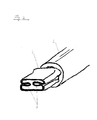
- Fig. 1 shows a plan view of the sleeve-side end of an aluminum line 2, wherein the aluminum line 2 consists of a plurality of spirally wound around a core around and arranged parallel to each other wires 6 and an insulation sheath 7.
- this insulation sheath 7 has been removed in order to allow the cold welding of this area of the light metal line 2 with the metal sleeve 3, here a light metal sleeve 3 made of soft annealed electrolytic copper.
- the inner diameter of the copper sleeve 3 is here slightly larger than the outer diameter of the stripped end of the aluminum line 2 designed.
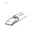
- Fig. 2 a first embodiment of a cold-welded to the contact-side end of an aluminum pipe 2 copper sleeve 3 is shown, in which case the cold welding is carried out so that the top and bottom of the metal shell 3 are designed substantially flat and in the side regions of projections 9 in the cross section of Aluminum line 2 are formed into it.
- the geometric shape of these projections 9 has no sharp transitions or edges in order to avoid severing individual (not shown) wires of the aluminum line within the formed copper sleeve 3. Rather, the introduction of the projections 9 takes place during the cold-welding operation in such a manner that the projections 9 slidably slide the wires (not shown) of the aluminum lead along the surfaces of the projections 9. There remains a particularly intimate and durable composite of aluminum pipe 2 and copper sleeve. 3
- Fig. 4 shows a second embodiment of a cold-welded to an aluminum line 2 copper sleeve 3.
- projections 9 are introduced into the side regions of the substantially flat-shaped copper sleeve 3.
- the dimensions of the copper sleeve 3 are designed so that the stripped wires 6 of the aluminum line 2 are received only in a partial length of the copper sleeve 3 and accordingly the aluminum line 2 facing away from the end of the copper sleeve 3 can be compressed beak-like, with only a narrow residual gap. 5 remains, which is particularly preferably already substantially liquid and gas-tight.
- Fig. 4 shows the connection of copper sleeve 3 and 2 aluminum line Fig. 3 arranged above a contact element 4.
- the outer shape of the deformed metal sleeve 3 is adapted to the shape of the connecting region of the contact element 4 (connecting lug) such that an angular offset of the metal sleeve 3 and contact element 4 can already be prevented without further ado.
- Via the end of the contact element 4 facing away from the aluminum line 2, the electrical connection with the contact of an electrical consumer (not shown) is then effected.
- FIG. 5 an inventive connecting element 1 is shown, which consists essentially of the aluminum line 2, the cold-welded copper tube 3 with the aluminum line 2 and a contact element 4 connected to the copper sleeve 3.
- the application of the curable Liquid optionally after cold welding of metal sleeve 3 and contact element 4 takes place substantially above the end of the copper sleeve 3 facing away from the aluminum line 2 and covers the schematically represented region 11 in such a manner that the copper sleeve 3 guides the aluminum line 2 towards the contact element 4 side gas-tight.
Landscapes
- Engineering & Computer Science (AREA)
- Manufacturing & Machinery (AREA)
- Connections Effected By Soldering, Adhesion, Or Permanent Deformation (AREA)
Applications Claiming Priority (1)
| Application Number | Priority Date | Filing Date | Title |
|---|---|---|---|
| DE102008031588A DE102008031588B4 (de) | 2008-07-03 | 2008-07-03 | Kontaktierung von Leichtmetallleitungen |
Publications (1)
| Publication Number | Publication Date |
|---|---|
| EP2141771A1 true EP2141771A1 (fr) | 2010-01-06 |
Family
ID=40872280
Family Applications (1)
| Application Number | Title | Priority Date | Filing Date |
|---|---|---|---|
| EP20090163591 Withdrawn EP2141771A1 (fr) | 2008-07-03 | 2009-06-24 | Mise en contact de conduites en métal léger |
Country Status (3)
| Country | Link |
|---|---|
| US (1) | US7828610B2 (fr) |
| EP (1) | EP2141771A1 (fr) |
| DE (1) | DE102008031588B4 (fr) |
Cited By (8)
| Publication number | Priority date | Publication date | Assignee | Title |
|---|---|---|---|---|
| WO2011091873A1 (fr) | 2010-01-26 | 2011-08-04 | Auto-Kabel Managementgesellschaft Mbh | Cosse de câble présentant une déformation en forme de coque et dispositif de fixation |
| CH705347A1 (de) * | 2011-08-04 | 2013-02-15 | Feller Ag | Verfahren zum Befestigen einer Litze an einer Montageplatte aus Metall. |
| EP2579390A1 (fr) * | 2011-10-05 | 2013-04-10 | WEITKOWITZ Kabelschuhe und Werkzeuge GmbH | Terminal en aluminium-cuivre et procédé de fabrication de celui-ci |
| AT512881A1 (de) * | 2012-05-11 | 2013-11-15 | Gebauer & Griller | Verbindung eines elektrischen Kabels mit einem Kontaktteil und Verfahren zur Herstellung dieser Verbindung |
| ES2524384R1 (es) * | 2012-12-20 | 2015-02-24 | Robert Bosch Gmbh | Procedimiento para unir hilos de conexión de un devanado de fase de un devanado de estator para una máquina eléctrica así como máquina eléctrica. |
| EP2899810A1 (fr) | 2014-01-24 | 2015-07-29 | Intercable GmbH | Cosse |
| FR3028677A1 (fr) * | 2014-11-19 | 2016-05-20 | Leoni Wiring Systems France | Assemblage d'un ensemble de raccordement electrique |
| EP3118932A1 (fr) * | 2015-07-13 | 2017-01-18 | VM Industries | Organe de connexion électrique pour éléments de câblage électrique |
Families Citing this family (39)
| Publication number | Priority date | Publication date | Assignee | Title |
|---|---|---|---|---|
| DE102008031588B4 (de) * | 2008-07-03 | 2011-03-24 | Lisa Dräxlmaier GmbH | Kontaktierung von Leichtmetallleitungen |
| DE102008058047B4 (de) * | 2008-11-18 | 2013-11-07 | Auto-Kabel Management Gmbh | Verbindung von elektrischen Leitungen mittels Ultraschallschweißen |
| DE102009059307A1 (de) * | 2009-12-23 | 2011-06-30 | Schunk Sonosystems GmbH, 35435 | Verfahren zum elektrisch leitenden Verbinden von Drähten |
| JP5557377B2 (ja) * | 2010-03-23 | 2014-07-23 | 矢崎総業株式会社 | 端子の電線に対する接続構造 |
| DE102010003599A1 (de) | 2010-04-01 | 2011-10-06 | Lisa Dräxlmaier GmbH | Verfahren zur Kabelkonfektionierung sowie konfektioniertes Kabel |
| CA2813953C (fr) * | 2010-10-06 | 2015-12-01 | Sonics & Materials Inc. | Systeme et procede pour terminer des conducteurs en aluminium |
| DE102011017070B4 (de) * | 2011-04-14 | 2013-10-31 | Auto-Kabel Management Gmbh | Herstellung eines elektrischen Kabels sowie Verfahren zur Herstellung einer Verbindung |
| US8826533B2 (en) * | 2011-06-24 | 2014-09-09 | Delphi Technologies, Inc. | Crimp connection to aluminum cable |
| JP5913851B2 (ja) * | 2011-07-20 | 2016-04-27 | 矢崎総業株式会社 | 電線の接続方法 |
| JP2013049070A (ja) * | 2011-08-30 | 2013-03-14 | Yazaki Corp | 電線の端末処理方法及び電線の端末構造 |
| JP2013109847A (ja) * | 2011-11-17 | 2013-06-06 | Yazaki Corp | 芯線止水構造及び芯線止水方法 |
| DE102011089207B4 (de) | 2011-12-20 | 2021-02-04 | Lisa Dräxlmaier GmbH | Verfahren zum Kontaktieren einer Litzenleitung mit einem Kontakt |
| JP6097769B2 (ja) * | 2012-02-11 | 2017-03-15 | アンフェノル−テュッヘル・エレクトロニクス・ゲーエムベーハー | 超音波溶接による電気的接続のための電気プラグコネクタ |
| JP5899593B2 (ja) * | 2012-07-31 | 2016-04-06 | 矢崎総業株式会社 | 圧着端子付きアルミ電線 |
| JP5884986B2 (ja) * | 2012-07-31 | 2016-03-15 | 矢崎総業株式会社 | 圧着端子付きアルミ電線 |
| EP2747205B1 (fr) * | 2012-12-18 | 2021-04-14 | Nexans | Procédé de liaison électrique conductrice d'un conducteur torsadé avec un élément de contact |
| DE102013201167A1 (de) * | 2013-01-24 | 2014-08-07 | Elringklinger Ag | Verfahren zum Herstellen einer elektrisch leitenden Verbindung zwischen einer elektrischen Leitung und einem elektrisch leitenden Bauteil und nach dem Verfahren hergestellte Baugruppe |
| JP6133079B2 (ja) * | 2013-02-22 | 2017-05-24 | 古河電気工業株式会社 | 接続構造体及びその接続方法 |
| DE102013101876B3 (de) | 2013-02-26 | 2014-06-12 | Innovations- und Informationszentrum Schneiden und Fügen e.V. | Verfahren zum stoffschlüssigen Fügen eines Kabels mit einem Anschlusselement sowie konfiguriertes Kabel |
| JP2014211953A (ja) * | 2013-04-17 | 2014-11-13 | 矢崎総業株式会社 | 電線の接続方法,接続装置 |
| DE102013209314B3 (de) * | 2013-05-21 | 2014-06-26 | Lisa Dräxlmaier GmbH | Verfahren zum elektrischen Verbinden einer elektrischen Leitung mit einem Kontaktteil |
| JP2014241680A (ja) * | 2013-06-11 | 2014-12-25 | 矢崎総業株式会社 | 電線の端子接合構造及び抵抗溶接用電極 |
| DE102013013151A1 (de) | 2013-08-08 | 2015-02-12 | Lisa Dräxlmaier GmbH | Vefahren zum elektrischen Verbinden der Litze eines elektrischen Leiters mit einem Leiteranschlusselement sowie konfektionierte elektrische Leitung |
| DE102013015302B4 (de) | 2013-09-14 | 2017-02-09 | Audi Ag | Verfahren zum Konditionieren der Endlitzen eines stromleitenden, flexiblen Kabels |
| DE102014004127B4 (de) | 2014-03-24 | 2015-12-17 | Lisa Dräxlmaier GmbH | Verfahren zum Verbinden einer elektrischen Leitung mit einem metallischen Kontaktelement, Verbindungselement sowie Sonotrode |
| DE102014005189B4 (de) | 2014-04-09 | 2020-03-26 | Lisa Dräxlmaier GmbH | Einrichthilfe eines Crimpautomaten sowie Verfahren zum Einrichten eines Crimpautomaten |
| CN104143707A (zh) * | 2014-08-05 | 2014-11-12 | 国家电网公司 | 一种用于变压器桩头与铝导线固定的铜铝过渡连接件 |
| WO2016054516A1 (fr) * | 2014-10-03 | 2016-04-07 | General Cable Technologies Corporation | Fil et procédés de préparation d'un fil destiné à recevoir un élément de contact |
| DE102015012906A1 (de) * | 2015-02-27 | 2016-09-01 | Gentherm Gmbh | Hülse, Kontaktier-Einrichtung und Verfahren zum Schweißen von dünnen strangförmigen Leitern mittels Ultraschall |
| DE102015210458A1 (de) * | 2015-06-08 | 2016-12-08 | Te Connectivity Germany Gmbh | Verfahren zum Verbinden eines ein unedles Metall aufweisenden Leiters mit einem Kupfer aufweisenden Anschlusselement mittels Verschweißen sowie eine dadurch hergestellte Anschlussanordnung |
| DE102015110593A1 (de) * | 2015-07-01 | 2017-01-05 | Lisa Dräxlmaier GmbH | Stecksicherungselement |
| US20180219303A1 (en) * | 2017-02-02 | 2018-08-02 | Hubbell Incorporated | Terminal connectors |
| CN106862691B (zh) * | 2017-03-08 | 2019-02-15 | 贵州电网有限责任公司电力科学研究院 | 一种铜铝过渡连接端子锡焊方法 |
| DE102017114994B3 (de) * | 2017-07-05 | 2018-05-09 | Lisa Dräxlmaier GmbH | Verfahren zum herstellen einer elektrischen leitungsanordnung |
| DE102017123864B3 (de) * | 2017-10-13 | 2019-04-04 | Lisa Dräxlmaier GmbH | Elektrische Leitungsanordnung mit Direktkontaktierung und Verfahren zu deren Herstellung |
| JP6927909B2 (ja) * | 2018-03-01 | 2021-09-01 | 矢崎総業株式会社 | 電線の導体の接合方法および電線 |
| JP6845188B2 (ja) * | 2018-07-13 | 2021-03-17 | 矢崎総業株式会社 | 端子付き電線及びその製造方法 |
| EP3997761A4 (fr) * | 2019-07-09 | 2023-07-12 | Elco Enterprises, Inc. | Dispositif de verrouillage de câble |
| JP7140797B2 (ja) * | 2020-05-27 | 2022-09-21 | 矢崎総業株式会社 | 端子接続構造 |
Citations (9)
| Publication number | Priority date | Publication date | Assignee | Title |
|---|---|---|---|---|
| US2806215A (en) | 1953-11-04 | 1957-09-10 | Aircraft Marine Prod Inc | Aluminum ferrule-copper tongue terminal and method of making |
| US3656092A (en) | 1970-08-07 | 1972-04-11 | Amp Inc | Terminal device for welded termination of electrical leads |
| US3955044A (en) | 1970-12-03 | 1976-05-04 | Amp Incorporated | Corrosion proof terminal for aluminum wire |
| EP0018863A1 (fr) * | 1979-05-07 | 1980-11-12 | The Bendix Corporation | Borne électrique du type à sertissage pour fil en aluminium |
| DE29903301U1 (de) | 1999-02-24 | 1999-05-12 | Auto Kabel Man Gmbh | Verbindung eines elektrischen Aluminiumkabels mit einem aus Kupfer o.dgl. Metall bestehenden Anschlußteil |
| DE19908031A1 (de) | 1999-02-24 | 2000-09-14 | Auto Kabel Man Gmbh | Verbindung eines elektrischen Aluminiumkabels mit einem aus Kupfer oder dergleichen Metall bestehenden Anschlußteil |
| DE10223397A1 (de) * | 2003-10-04 | 2003-12-24 | Edelhoff Adolf Feindrahtwerk | Verfahren und Verbindung zur Kontaktierung eines Aluminiumkabels |
| DE10346160B3 (de) * | 2002-05-25 | 2005-07-14 | Feindrahtwerk Adolf Edelhoff Gmbh & Co. | Verfahren und Verbindung zur Kontaktierung eines Aluminiumkabels |
| DE102005030248B3 (de) * | 2005-06-29 | 2006-08-31 | Feindrahtwerk Adolf Edelhoff Gmbh & Co | Verfahren und Verbindung zur Kontaktierung eines isolierten Kabels |
Family Cites Families (18)
| Publication number | Priority date | Publication date | Assignee | Title |
|---|---|---|---|---|
| US2385792A (en) * | 1942-08-17 | 1945-10-02 | Aircraft Marine Prod Inc | Electrical connector |
| US2405111A (en) * | 1942-09-25 | 1946-08-06 | Aircraft Marine Prod Inc | Electrical connection |
| US2513365A (en) * | 1945-05-18 | 1950-07-04 | Burndy Engineering Co Inc | Soldered aluminum-to-copper connection |
| US2655641A (en) * | 1948-10-29 | 1953-10-13 | Aircraft Marine Prod Inc | Electrical connector having a mercury amalgam coating on its inner surface |
| US2815497A (en) * | 1953-04-23 | 1957-12-03 | Amp Inc | Connector for aluminum wire |
| US2769965A (en) * | 1956-03-07 | 1956-11-06 | Thomas & Betts Corp | Nylon-jacketed connector |
| DE1934213C3 (de) * | 1969-07-05 | 1980-07-10 | Robert Bosch Gmbh, 7000 Stuttgart | Verfahren zur Herstellung eines Kommutators |
| US3842487A (en) * | 1971-10-18 | 1974-10-22 | Essex International Inc | Terminating of electrical conductors |
| US3876280A (en) * | 1973-10-02 | 1975-04-08 | Coatings Inc | Electric terminator comprising one-piece bimetallic connector and method for making such connector |
| US3949466A (en) * | 1974-05-28 | 1976-04-13 | Arthur D. Little Inc. | Process for forming an aluminum electrical conducting wire junction end piece |
| US4039244A (en) * | 1976-04-09 | 1977-08-02 | Coatings Inc. | Bimetallic electrical connector and method for making the same |
| US4098449A (en) * | 1977-03-28 | 1978-07-04 | General Electric Company | Terminal connection for aluminum conductor and method of making |
| US4621760A (en) * | 1985-07-09 | 1986-11-11 | Dana Corporation | Method of producing a friction welded article |
| US5749756A (en) * | 1995-10-27 | 1998-05-12 | The Whitaker Corporation | Sealed corrosion-proof crimped terminal of splice |
| JP4422391B2 (ja) * | 2002-08-07 | 2010-02-24 | 矢崎総業株式会社 | 電線と端子の接続方法 |
| US7947904B2 (en) * | 2005-04-01 | 2011-05-24 | Autonetworks Technologies, Ltd. | Conductor and wire harness |
| JP5235369B2 (ja) * | 2007-09-18 | 2013-07-10 | 株式会社オートネットワーク技術研究所 | ワイヤーハーネスおよびその製造方法ならびに絶縁電線の接続方法 |
| DE102008031588B4 (de) * | 2008-07-03 | 2011-03-24 | Lisa Dräxlmaier GmbH | Kontaktierung von Leichtmetallleitungen |
-
2008
- 2008-07-03 DE DE102008031588A patent/DE102008031588B4/de active Active
-
2009
- 2009-06-24 EP EP20090163591 patent/EP2141771A1/fr not_active Withdrawn
- 2009-07-01 US US12/496,022 patent/US7828610B2/en not_active Expired - Fee Related
Patent Citations (9)
| Publication number | Priority date | Publication date | Assignee | Title |
|---|---|---|---|---|
| US2806215A (en) | 1953-11-04 | 1957-09-10 | Aircraft Marine Prod Inc | Aluminum ferrule-copper tongue terminal and method of making |
| US3656092A (en) | 1970-08-07 | 1972-04-11 | Amp Inc | Terminal device for welded termination of electrical leads |
| US3955044A (en) | 1970-12-03 | 1976-05-04 | Amp Incorporated | Corrosion proof terminal for aluminum wire |
| EP0018863A1 (fr) * | 1979-05-07 | 1980-11-12 | The Bendix Corporation | Borne électrique du type à sertissage pour fil en aluminium |
| DE29903301U1 (de) | 1999-02-24 | 1999-05-12 | Auto Kabel Man Gmbh | Verbindung eines elektrischen Aluminiumkabels mit einem aus Kupfer o.dgl. Metall bestehenden Anschlußteil |
| DE19908031A1 (de) | 1999-02-24 | 2000-09-14 | Auto Kabel Man Gmbh | Verbindung eines elektrischen Aluminiumkabels mit einem aus Kupfer oder dergleichen Metall bestehenden Anschlußteil |
| DE10346160B3 (de) * | 2002-05-25 | 2005-07-14 | Feindrahtwerk Adolf Edelhoff Gmbh & Co. | Verfahren und Verbindung zur Kontaktierung eines Aluminiumkabels |
| DE10223397A1 (de) * | 2003-10-04 | 2003-12-24 | Edelhoff Adolf Feindrahtwerk | Verfahren und Verbindung zur Kontaktierung eines Aluminiumkabels |
| DE102005030248B3 (de) * | 2005-06-29 | 2006-08-31 | Feindrahtwerk Adolf Edelhoff Gmbh & Co | Verfahren und Verbindung zur Kontaktierung eines isolierten Kabels |
Cited By (11)
| Publication number | Priority date | Publication date | Assignee | Title |
|---|---|---|---|---|
| WO2011091873A1 (fr) | 2010-01-26 | 2011-08-04 | Auto-Kabel Managementgesellschaft Mbh | Cosse de câble présentant une déformation en forme de coque et dispositif de fixation |
| US8540535B2 (en) | 2010-01-26 | 2013-09-24 | Auto Kabel Managementgesellschaft Mbh | Cable lug with shell-shaped part and fastening device |
| CH705347A1 (de) * | 2011-08-04 | 2013-02-15 | Feller Ag | Verfahren zum Befestigen einer Litze an einer Montageplatte aus Metall. |
| EP2579390A1 (fr) * | 2011-10-05 | 2013-04-10 | WEITKOWITZ Kabelschuhe und Werkzeuge GmbH | Terminal en aluminium-cuivre et procédé de fabrication de celui-ci |
| AT512881A1 (de) * | 2012-05-11 | 2013-11-15 | Gebauer & Griller | Verbindung eines elektrischen Kabels mit einem Kontaktteil und Verfahren zur Herstellung dieser Verbindung |
| AT512881B1 (de) * | 2012-05-11 | 2014-03-15 | Gebauer & Griller | Verbindung eines elektrischen Kabels mit einem Kontaktteil und Verfahren zur Herstellung dieser Verbindung |
| ES2524384R1 (es) * | 2012-12-20 | 2015-02-24 | Robert Bosch Gmbh | Procedimiento para unir hilos de conexión de un devanado de fase de un devanado de estator para una máquina eléctrica así como máquina eléctrica. |
| EP2899810A1 (fr) | 2014-01-24 | 2015-07-29 | Intercable GmbH | Cosse |
| FR3028677A1 (fr) * | 2014-11-19 | 2016-05-20 | Leoni Wiring Systems France | Assemblage d'un ensemble de raccordement electrique |
| EP3024092A1 (fr) * | 2014-11-19 | 2016-05-25 | Leoni Wiring Systems France | Assemblage d'un ensemble de raccordement électrique |
| EP3118932A1 (fr) * | 2015-07-13 | 2017-01-18 | VM Industries | Organe de connexion électrique pour éléments de câblage électrique |
Also Published As
| Publication number | Publication date |
|---|---|
| US7828610B2 (en) | 2010-11-09 |
| DE102008031588B4 (de) | 2011-03-24 |
| DE102008031588A1 (de) | 2010-01-14 |
| US20100003867A1 (en) | 2010-01-07 |
Similar Documents
| Publication | Publication Date | Title |
|---|---|---|
| DE102008031588B4 (de) | Kontaktierung von Leichtmetallleitungen | |
| EP3602690B1 (fr) | Liaison d'une partie de raccordement à un câble toronné | |
| EP2227347B8 (fr) | CONNECTEUR METHOD POUR CONNECTER CONDUCTEUR TORSADE D'ALUMINIUM& xA;PAR SOUDAGE PAR ULTRASONS EN TORSION | |
| EP2362491B1 (fr) | Procédé de connexion d'une conduite électrique avec un élément de raccordement électrique | |
| DE19908031A1 (de) | Verbindung eines elektrischen Aluminiumkabels mit einem aus Kupfer oder dergleichen Metall bestehenden Anschlußteil | |
| EP2553766A1 (fr) | Procédé de confection de câble et câble ainsi confectionné | |
| EP2371036B1 (fr) | Liaison de contact électrique et procédé pour réaliser une liaison de contact électrique | |
| DE19902405B4 (de) | Verfahren zur Herstellung einer korrosionsresistenten, elektrischen Verbindung | |
| EP3609023B1 (fr) | Procédé et dispositif de fabrication d'un raccordement électrique et conduite électrique | |
| DE102007047752A1 (de) | Leiter mit Kontaktteil | |
| DE102010027033A1 (de) | Leiter mit Kontaktteil | |
| DE102012206145A1 (de) | Verfahren zum Fertigen einer Drahtabgangsanordnung für eine elektrische Maschine sowie entsprechende Drahtabgangsanordnung | |
| DE102011011409B4 (de) | Anschlussteil und Verbindung für elektrische Anlagen | |
| DE102019112328A1 (de) | Elektrische Anschlusskonsole für KFZ Bordnetzleitung | |
| DE102010009284A1 (de) | Leitungseinheit mit Dichtfunktion | |
| DE102013013151A1 (de) | Vefahren zum elektrischen Verbinden der Litze eines elektrischen Leiters mit einem Leiteranschlusselement sowie konfektionierte elektrische Leitung | |
| DE102018100020B4 (de) | Verfahren und Vorrichtung zur Herstellung einer Verbindung zwischen einem Crimpkontakt und einem Litzenleiter | |
| EP3451455B1 (fr) | Procédé de fabrication d'une liaison électrique et une ligne électrique | |
| EP2672569B1 (fr) | Procédé destiné à relier des conducteurs électriques et un faisceau conducteur | |
| WO2012175442A1 (fr) | Ligne électrique et procédé de fabrication d'une telle ligne électrique | |
| DE102011089206B4 (de) | Verfahren zum Kontaktieren einer Litzenleitung mit einem Kontakt | |
| DE102009056799A1 (de) | Leiter mit Kontaktteil | |
| DE102015117020B4 (de) | Verfahren zum Herstellen einer Leitungsabdichtung eines Leitungsstrangs und Verfahren zur Herstellung einer gedichteten Leitungsverbindung | |
| DE102010053768B4 (de) | Verfahren zum Verbinden eines Aluminiumkabels mit einem Anschlussteil | |
| DE102014206283B3 (de) | Elektrische Kontaktverbindung sowie Verfahren zur Herstellung einer Kontaktverbindung |
Legal Events
| Date | Code | Title | Description |
|---|---|---|---|
| PUAI | Public reference made under article 153(3) epc to a published international application that has entered the european phase |
Free format text: ORIGINAL CODE: 0009012 |
|
| AK | Designated contracting states |
Kind code of ref document: A1 Designated state(s): AT BE BG CH CY CZ DE DK EE ES FI FR GB GR HR HU IE IS IT LI LT LU LV MC MK MT NL NO PL PT RO SE SI SK TR |
|
| 17P | Request for examination filed |
Effective date: 20100628 |
|
| 17Q | First examination report despatched |
Effective date: 20100716 |
|
| RIC1 | Information provided on ipc code assigned before grant |
Ipc: H01R 4/18 20060101ALI20150429BHEP Ipc: H01R 4/62 20060101ALI20150429BHEP Ipc: H01R 13/03 20060101ALI20150429BHEP Ipc: H01R 4/20 20060101ALI20150429BHEP Ipc: H01R 4/72 20060101ALI20150429BHEP Ipc: H01R 43/02 20060101ALI20150429BHEP Ipc: H01R 4/04 20060101AFI20150429BHEP |
|
| GRAP | Despatch of communication of intention to grant a patent |
Free format text: ORIGINAL CODE: EPIDOSNIGR1 |
|
| INTG | Intention to grant announced |
Effective date: 20150615 |
|
| RIN1 | Information on inventor provided before grant (corrected) |
Inventor name: KALLEE, KLAUS Inventor name: LEHMANN, LUTZ |
|
| STAA | Information on the status of an ep patent application or granted ep patent |
Free format text: STATUS: THE APPLICATION IS DEEMED TO BE WITHDRAWN |
|
| 18D | Application deemed to be withdrawn |
Effective date: 20151027 |