EP2141446B1 - Optical tomographic image photographing apparatus - Google Patents
Optical tomographic image photographing apparatus Download PDFInfo
- Publication number
- EP2141446B1 EP2141446B1 EP09164546.5A EP09164546A EP2141446B1 EP 2141446 B1 EP2141446 B1 EP 2141446B1 EP 09164546 A EP09164546 A EP 09164546A EP 2141446 B1 EP2141446 B1 EP 2141446B1
- Authority
- EP
- European Patent Office
- Prior art keywords
- image
- tomographic image
- eye
- optical
- fundus
- Prior art date
- Legal status (The legal status is an assumption and is not a legal conclusion. Google has not performed a legal analysis and makes no representation as to the accuracy of the status listed.)
- Active
Links
- 230000003287 optical effect Effects 0.000 title claims description 135
- 238000005259 measurement Methods 0.000 claims description 42
- 230000003595 spectral effect Effects 0.000 claims description 17
- 210000001110 axial length eye Anatomy 0.000 claims description 9
- 230000008859 change Effects 0.000 claims description 2
- 210000003161 choroid Anatomy 0.000 claims description 2
- 210000001525 retina Anatomy 0.000 claims description 2
- 239000006185 dispersion Substances 0.000 description 35
- 238000012937 correction Methods 0.000 description 34
- 238000012545 processing Methods 0.000 description 20
- 210000001508 eye Anatomy 0.000 description 19
- 230000002207 retinal effect Effects 0.000 description 14
- 239000013307 optical fiber Substances 0.000 description 10
- 230000010363 phase shift Effects 0.000 description 7
- 239000000835 fiber Substances 0.000 description 6
- 230000006870 function Effects 0.000 description 6
- 230000007246 mechanism Effects 0.000 description 6
- 230000001427 coherent effect Effects 0.000 description 4
- 230000000694 effects Effects 0.000 description 4
- 239000000284 extract Substances 0.000 description 4
- 238000000034 method Methods 0.000 description 4
- 230000000630 rising effect Effects 0.000 description 4
- 210000003128 head Anatomy 0.000 description 3
- 210000003583 retinal pigment epithelium Anatomy 0.000 description 3
- 238000004364 calculation method Methods 0.000 description 2
- 238000001514 detection method Methods 0.000 description 2
- 230000000193 eyeblink Effects 0.000 description 2
- 238000012986 modification Methods 0.000 description 2
- 230000004048 modification Effects 0.000 description 2
- 230000004044 response Effects 0.000 description 2
- 210000004204 blood vessel Anatomy 0.000 description 1
- 210000005252 bulbus oculi Anatomy 0.000 description 1
- 239000000470 constituent Substances 0.000 description 1
- 238000007796 conventional method Methods 0.000 description 1
- 230000001419 dependent effect Effects 0.000 description 1
- 238000002474 experimental method Methods 0.000 description 1
- 238000009499 grossing Methods 0.000 description 1
- 238000005286 illumination Methods 0.000 description 1
- 208000014733 refractive error Diseases 0.000 description 1
- 238000005070 sampling Methods 0.000 description 1
- 230000035945 sensitivity Effects 0.000 description 1
- 238000004088 simulation Methods 0.000 description 1
- 238000013519 translation Methods 0.000 description 1
Images


Classifications
-
- G—PHYSICS
- G01—MEASURING; TESTING
- G01B—MEASURING LENGTH, THICKNESS OR SIMILAR LINEAR DIMENSIONS; MEASURING ANGLES; MEASURING AREAS; MEASURING IRREGULARITIES OF SURFACES OR CONTOURS
- G01B9/00—Measuring instruments characterised by the use of optical techniques
- G01B9/02—Interferometers
- G01B9/02015—Interferometers characterised by the beam path configuration
- G01B9/02029—Combination with non-interferometric systems, i.e. for measuring the object
- G01B9/0203—With imaging systems
-
- A—HUMAN NECESSITIES
- A61—MEDICAL OR VETERINARY SCIENCE; HYGIENE
- A61B—DIAGNOSIS; SURGERY; IDENTIFICATION
- A61B3/00—Apparatus for testing the eyes; Instruments for examining the eyes
- A61B3/10—Objective types, i.e. instruments for examining the eyes independent of the patients' perceptions or reactions
- A61B3/102—Objective types, i.e. instruments for examining the eyes independent of the patients' perceptions or reactions for optical coherence tomography [OCT]
-
- G—PHYSICS
- G01—MEASURING; TESTING
- G01B—MEASURING LENGTH, THICKNESS OR SIMILAR LINEAR DIMENSIONS; MEASURING ANGLES; MEASURING AREAS; MEASURING IRREGULARITIES OF SURFACES OR CONTOURS
- G01B9/00—Measuring instruments characterised by the use of optical techniques
- G01B9/02—Interferometers
- G01B9/02041—Interferometers characterised by particular imaging or detection techniques
- G01B9/02044—Imaging in the frequency domain, e.g. by using a spectrometer
-
- G—PHYSICS
- G01—MEASURING; TESTING
- G01B—MEASURING LENGTH, THICKNESS OR SIMILAR LINEAR DIMENSIONS; MEASURING ANGLES; MEASURING AREAS; MEASURING IRREGULARITIES OF SURFACES OR CONTOURS
- G01B9/00—Measuring instruments characterised by the use of optical techniques
- G01B9/02—Interferometers
- G01B9/02055—Reduction or prevention of errors; Testing; Calibration
- G01B9/02062—Active error reduction, i.e. varying with time
- G01B9/02064—Active error reduction, i.e. varying with time by particular adjustment of coherence gate, i.e. adjusting position of zero path difference in low coherence interferometry
-
- G—PHYSICS
- G01—MEASURING; TESTING
- G01B—MEASURING LENGTH, THICKNESS OR SIMILAR LINEAR DIMENSIONS; MEASURING ANGLES; MEASURING AREAS; MEASURING IRREGULARITIES OF SURFACES OR CONTOURS
- G01B9/00—Measuring instruments characterised by the use of optical techniques
- G01B9/02—Interferometers
- G01B9/02055—Reduction or prevention of errors; Testing; Calibration
- G01B9/02075—Reduction or prevention of errors; Testing; Calibration of particular errors
- G01B9/02078—Caused by ambiguity
-
- G—PHYSICS
- G01—MEASURING; TESTING
- G01B—MEASURING LENGTH, THICKNESS OR SIMILAR LINEAR DIMENSIONS; MEASURING ANGLES; MEASURING AREAS; MEASURING IRREGULARITIES OF SURFACES OR CONTOURS
- G01B9/00—Measuring instruments characterised by the use of optical techniques
- G01B9/02—Interferometers
- G01B9/02083—Interferometers characterised by particular signal processing and presentation
- G01B9/02089—Displaying the signal, e.g. for user interaction
-
- G—PHYSICS
- G01—MEASURING; TESTING
- G01B—MEASURING LENGTH, THICKNESS OR SIMILAR LINEAR DIMENSIONS; MEASURING ANGLES; MEASURING AREAS; MEASURING IRREGULARITIES OF SURFACES OR CONTOURS
- G01B9/00—Measuring instruments characterised by the use of optical techniques
- G01B9/02—Interferometers
- G01B9/0209—Low-coherence interferometers
- G01B9/02091—Tomographic interferometers, e.g. based on optical coherence
-
- G—PHYSICS
- G01—MEASURING; TESTING
- G01N—INVESTIGATING OR ANALYSING MATERIALS BY DETERMINING THEIR CHEMICAL OR PHYSICAL PROPERTIES
- G01N21/00—Investigating or analysing materials by the use of optical means, i.e. using sub-millimetre waves, infrared, visible or ultraviolet light
- G01N21/17—Systems in which incident light is modified in accordance with the properties of the material investigated
- G01N21/47—Scattering, i.e. diffuse reflection
- G01N21/4795—Scattering, i.e. diffuse reflection spatially resolved investigating of object in scattering medium
Definitions
- the present invention relates to an optical tomographic image photographing apparatus arranged to photograph a tomographic image of an examined object.
- optical tomographic image photographing apparatus arranged to photograph a tomographic image of an examined object
- OCT optical coherence tomograph
- This apparatus is used for obtaining a tomographic image of a living body part such as an eyeball and a skin, for example.
- an optical-path-length varying optical member e.g., a reference mirror
- an apparatus arranged to photograph a tomographic image of a fundus of an examinee's eye to obtain a fundus tomographic image which is formed by interference light of measurement light projected onto the fundus and reference light
- it is necessary to perform adjustment of the optical path length by moving an optical-path-length varying optical member (e.g., a reference mirror) corresponding to an eye axial length of the examinee's eye.
- an optical-path-length varying optical member e.g., a reference mirror
- the reference mirror is moved from an initial position at which the optical path length of the reference light is shortest in a direction such that the optical path length is made longer, the presence or absence of the fundus tomographic image is determined at each moving position, and the reference mirror is moved based on a result of the determination.
- a normal image or an inverted image of the fundus tomographic image is obtained in accordance with the position of the reference mirror (sometimes no fundus tomographic image is obtained).
- the reference mirror is moved from a position at which the optical path length of the reference light is shortest or a position at which the optical path length of the reference light is longest, by which a firstly obtained fundus tomographic image is previously set to be a normal image or an inverted image.
- the firstly obtained tomographic image is set to be the inverted image.
- the firstly obtained tomographic image is identified as the inverted image of the fundus tomographic image, and the reference mirror is moved from the position at which the inverted image is obtained in a direction such that the normal image is obtained, so that the normal image is displayed on a screen of a display monitor.
- the technique described above requires long time to perform the adjustment of the optical path length because the optical-path-length varying optical member should be moved from the position at which the optical path length of the reference light is shortest or from the position at which the optical path length of the reference light is longest.
- a tomographic image desired by an examiner could not be displayed if the examinee's eye blinks when the optical-path-length varying optical member is located at a position at which the previously specified tomographic image (e.g., an inverted image) is obtained during the adjustment of the optical path length.
- An object of the invention is to overcome the problems described above and to provide a fundus photographing apparatus which allows for smooth adjustment of the optical path length with respect to an examined object.
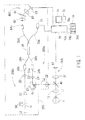
- FIG. 1 is a view showing an optical system and a control system of the optical tomographic image photographing apparatus according to the present preferred embodiment of the present invention.
- a fundus photographing apparatus which is one of ophthalmic photographing apparatuses, is taken as an example.
- a depth direction of an examinee's eye E is referred to as a Z-direction (a direction of an optical axis L1)
- a horizontal direction on a plane which is perpendicular to the depth direction is referred to as an X-direction
- a vertical direction is referred to as a Y-direction.
- the optical system is provided with an interference optical system (an OCT optical system) 200 and a fundus observation optical system 300.
- the interference optical system 200 is arranged to make a portion of low coherent light into measurement light, make another portion of the low coherent light into reference light, and combine the reference light and reflection light formed by the measurement light in order to make interference light.
- the fundus observation optical system 300 obtains a fundus image for fundus observation by photographing a fundus of the eye E illuminated with infrared light by using a two-dimensional photodetector.
- the interference optical system 200 includes a measurement optical system 200a and a reference light optical system 200b.
- the interference optical system 200 includes a spectral optical system 800 arranged to disperse the interference light of the reference light and the measurement light for each frequency (wavelength) and make the dispersed interference light photo-received by photo-receiving means (in the present preferred embodiment of the present invention, a one-dimensional photo-detector).
- a dichroic mirror 40 has properties of reflecting light having specific wavelength components that is used as the measurement light of the OCT optical system 200 and transmitting light having specific wavelength components that is used as the observation light of the fundus observation optical system 300.
- An OCT light source 27 is arranged to emit low coherent light to be used as the measurement light and the reference light of the OCT optical system 200.
- An SLD light source is preferably used as the OCT light source 27. Specifically, a light source having a center wavelength of 840 nm and a bandwidth of 50 nm is used, for example.
- a fiber coupler 26 functions as both of a light dividing member and a light combining member. The light from the OCT light source 27 passes through an optical fiber 38a that functions as a light guide, and is divided into the reference light and the measurement light by the fiber coupler 26. The measurement light passes through an optical fiber 38b and heads for the eye E. The reference light passes through an optical fiber 38c and heads for a reference mirror 31.
- an end portion 39b of the optical fiber 38b from which the measurement light exits On an optical path where the measurement light travels to the eye E, an end portion 39b of the optical fiber 38b from which the measurement light exits, a focusing lens 24 which is movable in an optical axis direction in accordance with refractive error of the eye E, a scanning unit 23 which is defined by a combination of two galvano mirrors capable of scanning the measurement light in the X- and Y-directions on the fundus by driving of a scanning driving mechanism 51, and a relay lens 22 are disposed.
- the dichroic mirror 40 and an objective lens 10 function as a light guiding optical system arranged to guide the OCT measurement light from the OCT optical system 200 to the fundus.
- the measurement light reflected from the fundus passes through the objective lens 10, is reflected by the dichroic mirror 40, and heads for the OCT optical system 200, where the measurement light enters the end portion 39b of the optical fiber 38b via the relay lens 22, the two galvano mirrors of the scanning unit 23, and the focusing lens 24.
- the measurement light which enters the end portion 39b reaches an end portion 84a of an optical fiber 38d via the optical fiber 38b, the fiber coupler 26, and the optical fiber 38d.
- the reference mirror 31 On an optical path where the reference light travels to the reference mirror 31, an end portion 39c of the optical fiber 38c from which the reference light exits, a collimator lens 29, and the reference mirror 31 are disposed.
- the reference mirror 31 is movable in an optical axis direction by a reference-mirror driving mechanism 50 in order to change the optical path length of the reference light.
- the reference light which is thus formed from the light emitted from the OCT light source 27, and the reflection light from the fundus which is formed from the measurement light with which the fundus is illuminated are combined by the fiber coupler 26 to be made into the interference light. Then, after passing through the optical fiber 38d, the interference light exits from the end portion 84a.
- the spectral optical system (a spectrometer unit) 800 arranged to disperse the interference light into frequency components in order to obtain an interference signal for each of the frequencies includes a collimator lens 80, a grating mirror (a diffraction grating) 81, a condenser lens 82, and a photodetector 83.
- a one-dimensional detector (a line sensor) which has sensitivity to an infrared range is used.
- the interference light exiting from the end portion 84a is made into parallel light by the collimator lens 80, and then is dispersed into the frequency components by the grating mirror 81.
- the interference light dispersed into the frequency components is collected on a photo-receiving surface of the photodetector 83 via the condenser lens 82.
- spectral information on interference fringes is recorded at the photodetector 83.
- the spectral information is inputted into a control unit 70, and is analyzed by performing Fourier transform thereon, whereby information in the depth direction of the eye E can be obtained.
- the control unit 70 can obtain a tomographic image by controlling the scanning unit 23 to scan the measurement light in a predetermined traverse direction on the fundus. For example, scanning the measurement light in the X- or Y-direction allows a tomographic image on an X-Z or Y-Z plane of the fundus to be obtained (in the present preferred embodiment of the present invention, a mode of thus obtaining the tomographic image by one-dimensionally scanning the measurement light on the fundus is referred to as B-scan) .
- the obtained tomographic image is stored in a memory 72 connected to the control unit 70. It is also possible to obtain a three-dimensional image of the fundus by two-dimensionally scanning the measurement light in the X- and Y-directions.
- dispersion correction processing includes shifting a phase of an interference component, lowering a peak of a multiplexed signal of each wavelength, and broadening a signal (lowering resolution).
- the phase subjected to the shifting is converted back for each wavelength in order to correct the lowering of the resolution due to the lowering of the interference signal.
- a phase shift ⁇ (k) as a function of the wave number k is previously obtained, and the shifting of the phase is converted back for each k value by using I(k) ⁇ exp -i ⁇ (k) .
- the phase shift ⁇ (k) to be subjected to the dispersion correction processing may be obtained previously by calibration, or the phase shift ⁇ (k) corresponding to the obtained tomographic image may be obtained.
- first dispersion correction data (a phase shift ⁇ 1(k)) which is calculated based on a fundus tomographic image being a normal image (visibility on the retinal surface side is higher) and second dispersion correction data (a phase shift ⁇ 2(k)) which is calculated based on a fundus tomographic image being an inverted image (visibility on the choroidal side is higher) are previously calculated and stored in the memory 72. Accordingly, the first dispersion correction data for performing dispersion correction processing on the normal image and the second dispersion correction data for performing dispersion correction processing on the inverted image are prepared.
- control unit 70 obtains the information in the depth direction of the eye E by performing Fourier transform on the spectral intensity I(k) which has been subjected to the dispersion correction processing by using the previously set dispersion correction data.
- the first dispersion correction data (the phase shift ⁇ 1(k)) is calculated in real time based on the fundus tomographic image being a normal image. Then, the spectral intensity I(k) which has been corrected by the first dispersion correction data is subjected to Fourier transform so as to obtain the information in the depth direction.
- the second dispersion correction data (the phase shift ⁇ 2(k)) is calculated in real time based on the fundus tomographic image being an inverted image. Then, the spectral intensity I(k) which has been corrected by the second dispersion correction data is subjected to Fourier transform so as to obtain the information in the depth direction. Even if the optical member for the dispersion correction processing is placed in one of the optical path of the reference light and the optical path of the measurement light, the dispersion correction processing described above can be performed to reverse the effects of the dispersion correction processing.
- the fundus observation optical system 300 is provided with the objective lens 10, an image-pickup lens 12, and a two-dimensional image-pickup element 13.
- the light reflected from the fundus illuminated by an illumination optical system for fundus observation passes through the objective lens 10, the dichroic mirror 40, and the image-pickup lens 12, and forms an image on the image-pickup element 13.
- An image-pickup signal outputted from the image-pickup element 13 is inputted into the control unit 70.
- the control unit 70 displays a fundus image picked up by the image-pickup element 13 on a screen of a display monitor 75.
- the fundus image picked up by the image-pickup element 13 is used for fundus observation and for alignment with the eye E at the time when the fundus tomographic image is obtained.
- the control unit 70 is connected with the monitor 75, the memory 72, a control section 74, the driving mechanism 50, a driving mechanism 24a arranged to move the focusing lens 24 in the optical axis direction, and other constituent elements.
- the control section 74 is provided with a measurement starting switch 74a, a measurement position setting switch 74b, an auto coherence switch 74c, and a mode changing switch 74d.
- a trigger signal for starting the adjustment of the optical path length corresponding to an eye axial length of the eye E is inputted to the control unit 70.
- Fig. 2 is a view showing an example of the tomographic image obtained (formed) by the OCT optical system 200.
- Image data G consists of first image data G1 and second image data G2 which is a mirror image of the first image data G1, and the first and second image data G1 and G2 are symmetric with respect to a depth position S at which the optical path length of the measurement light and the optical path length of the reference light become equal.
- the control unit 70 extracts one of the first image data G1 and the second image data G2 in the image data G and displays the extracted one on the screen of the monitor 75. In the present preferred embodiment of the present invention, the first image data G1 is extracted.
- visibility is highest at the depth position at which the optical path length of the measurement light and the optical path length of the reference light become equal (a depth position corresponding to the location of the reference mirror 31) and is lowered with distance from the depth position. Therefore, an image with high visibility and high resolution is obtained in a fundus portion close to the depth position, while an image with less visibility and less resolution is obtained in a portion distant from the depth position.
- the apparatus has such a configuration that a photographing mode according to an observed portion is selectable in order that a fundus portion desired by an examiner can be observed with high visibility and high resolution.
- the photographing mode is previously selectable between a retinal mode of displaying a retinal surface side portion with high visibility (a first mode for observing the front side of the fundus) and a choroidal mode of displaying a choroidal side portion with high visibility (a second mode for observing the back side of the fundus).
- the mode changing switch 74d for selecting either of the modes is provided to the control section 74.
- the control unit 70 controls the movement of the reference mirror 31 in response to a mode selection signal inputted from the mode changing switch 74d.
- the reference mirror 31 When the reference mirror 31 is located such that the depth position at which the optical path length of the measurement light and the optical path length of the reference light become equal is positioned on the front side of the retinal surface, a fundus tomographic image whose visibility is higher on the retinal surface side and lower on the choroidal side (i.e., a normal image) is obtained.
- the first image data G1 and the second image data G2 which is a mirror image of the first image data G1 face each other.
- the reference mirror 31 when the reference mirror 31 is located such that the depth position at which the optical path length of the measurement light and the optical path length of the reference light become equal is positioned on the back side of the retinal surface, a fundus tomographic image whose visibility is higher on the choroidal side and lower on the retinal surface side (i.e., an inverted image) is obtained.
- the first image data G1 and the second image data G2 which is a mirror image of the first image data G1 face opposite directions from each other.
- the control unit 70 reads out the first dispersion correction data (for a normal image) as a dispersion correction value for correcting the effects of the dispersion from the memory 75, corrects data on the spectral intensity outputted from the photodetector 83 by using the first dispersion correction data, and generates tomographic image data by performing Fourier transform on the corrected spectral intensity data. Accordingly, the normal image of the fundus tomographic image is obtained with high visibility and high resolution, and the inverted image of the fundus tomographic image is obtained with blur and low resolution due to the difference in the dispersion correction data.
- the control unit 70 reads out the second dispersion correction data (for an inverted image) as a dispersion correction value for correcting the effects of the dispersion from the memory 75, corrects data on the spectral intensity outputted from the photodetector 83 by using the second dispersion correction value, and generates tomographic image data by performing Fourier transform on the corrected spectral intensity data. Accordingly, the inverted image of the fundus tomographic image is obtained with high visibility and high resolution, and the normal image of the fundus tomographic image is obtained with blur and low resolution due to the difference in the dispersion correction data.
- the descriptions provided below refer to the first image data G1 in which the fundus tomographic image whose visibility is higher on the front surface side of the fundus than the choroidal side is identified as the normal image, and the fundus tomographic image whose visibility is higher on the choroidal side than the front surface side of the fundus is identified as the inverted image.
- the examiner performs alignment in order to bring a measurement optical axis to the pupil center on an image photographed by a camera for anterior-segment observation (not shown), and then makes the examinee to fixate a movable fixation lamp (not shown) so that a desired portion is measured.
- the examiner selects an observation mode of the fundus tomographic image by using the mode changing switch 74d. The following descriptions are provided based on a situation in which the retinal mode is selected.
- Fig. 3 is a view showing the fundus observation image obtained by the fundus observation optical system 300 on the screen of the monitor 75.
- the examiner performs focusing on the fundus based on the infrared fundus image on the monitor 75, and then presses the auto coherence switch 74c.
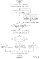
- the control unit 70 controls driving of the driving mechanism 50 based on an operation signal inputted from the auto coherence switch 74c to move the reference mirror 31 and perform adjustment of the optical path length of the reference light in order to obtain the normal image of the fundus tomographic image.
- control unit 70 moves the reference mirror 31 from a set initial position in one direction in given steps, determines whether a firstly obtained tomographic image is the normal image or the inverted image by image processing, and controls a direction of subsequent movement of the reference mirror 31 based on a result of the determination and the set observation mode.
- the reference mirror 31 is movable in a range between a movement limiting position K1 in a direction such that the optical path length of the reference light is made shorter and a movement limiting position K2 in a direction such that the optical path length of the reference light is made longer.
- the initial position (a movement start position) of the reference mirror 31 during the automatic adjustment of the optical path length is set at some midpoint in the movable range of the reference mirror 31 corresponding to the eye axial length of the examinee's eye (i.e., a position such that the optical path length of the reference light can be made longer and shorter), and is preferably set in the vicinity of a position in response to the examinee's eye having an average eye axial length (e.g., 24mm).
- the initial position is set at a position corresponding to an eye axial length (20 mm) which is slightly shorter than the average eye axial length (24 mm). Accordingly, the normal image of the fundus tomographic image is obtained when the tomographic image of the examinee's eye having the eye axial length of 20 mm is obtained with the reference mirror 31 being located at the initial position.
- control unit 70 After the control unit 70 obtains the tomographic image at the previously set initial position, the control unit 70 moves the reference mirror 31 in given steps in the direction such that the optical path length of the reference light is made longer (a direction such that the difference between the optical path length of the reference light and the optical path length of the measurement light is made shorter) while sequentially obtaining a tomographic image at each moving position, in order to search for a position at which a fundus tomographic image is obtained.
- the control unit 70 analyzes the tomographic image obtained at the position, and performs determination of the presence or absence of the fundus tomographic image, determination whether the fundus tomographic image is the normal image or the inverted image, and detection of an image position.
- the step for moving the reference mirror 31 if a photographing range Z1 in the depth direction of the first image data G1 for the normal image is 2 mm, the reference mirror 31 is moved so that a photographing region on the fundus is moved in about 2 mm steps.
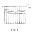
- the control unit 70 sets aplurality of scanning lines for scanning in the depth direction on the tomographic image (a direction of A-scan) as shown in Fig. 5 , and obtains luminance distribution data on each scanning line.
- the tomographic image is split into eleven, and the scanning lines are defined by ten splittinglines.
- data in the vicinity of the upper end of the tomographic image e.g., 10% of the tomographic image in the upper portion
- control unit 70 extracts data at one point out of every three points in the depth direction (thinning).
- Fig. 6 is a view showing a variation of the luminance distribution in the depth direction of the fundus tomographic image.
- the control unit 70 calculates the maximum luminance value in the luminance distribution of each scanning line, calculates the detected position of the maximum luminance value in the depth direction, and determines the presence or absence of the fundus tomographic image in the whole tomographic image based on a result of the calculation for each scanning line.
- the control unit 70 calculates the average value of the maximum luminance values of the respective scanning lines and detects the presence of the fundus tomographic image if the calculated average value is equal to or greater than a predetermined threshold value (e.g., equal to or greater than 35 where the luminance value is indicated by 256 levels), and determines the absence of the fundus tomographic image if the calculated average value is smaller than the predetermined threshold value (e.g., smaller than 35 where the luminance value is indicated by 256 levels).
- a predetermined threshold value e.g., equal to or greater than 35 where the luminance value is indicated by 256 levels
- control unit 70 moves the reference mirror 31 to the next previously set moving position and determines the presence or absence of the fundus tomographic image based on the tomographic image which is obtained at the moving position. In this way, the control unit 70 moves the reference mirror 31 in predetermined steps until the presence of the fundus tomographic image is detected.
- control unit 70 If no fundus tomographic image is detected even though the reference mirror 31 reaches the movement limiting position K2, the control unit 70 returns the reference mirror 31 to the initial position and moves the reference mirror 31 in the direction such that the optical path length of the reference light is made shorter in predetermined steps until the presence of the fundus tomographic image is detected (the first tomographic image is obtained).
- the control unit 70 detects the average position of the detected positions of the maximum luminance values in the respective scanning lines calculated as described above as an image position P1 of the fundus tomographic image. Then, the control unit 70 calculates a deviation amount Lg from the depth position S at which the optical path length of the measurement light and the optical path length of the reference light become equal (the upper end position of the first image data G1) to the image position P1. In other words, the control unit 70 detects the image position of the fundus tomographic image with respect to the depth position S at which the optical path length of the measurement light and the optical path length of the reference light become equal (see Fig. 8 ).
- the control unit 70 determines that the normal image and the inverted image of the fundus tomographic image are coexistent if the image position P1 of the fundus tomographic image calculated as described above is located in the vicinity of the upper end of the tomographic image (e.g., in a region corresponding to one fourth of the tomographic image in the upper portion). In such a case, the control unit 70 moves the reference mirror 31 by a predetermined amount in a direction such that only the normal image is obtained (the direction such that the optical path length of the reference light is made shorter).
- a movement direction and a movement amount of the reference mirror 31, which are required for bringing the state that the normal image and the inverted image are coexistent to a state that only the normal image is obtained, are previously calculated by experiment or simulation, and the movement direction and amount are previously stored in the memory 72.
- control unit 70 determines that only one of the normal image and the inverted image of the fundus tomographic image is present in the tomographic image. In this case, the control unit 70 determines whether the tomographic image is the normal image or the inverted image for each scanning line based on the luminance distribution calculated as described above.
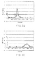
- Figs. 7A and 7B are views showing examples of the luminance distribution data on each scanning line.
- Fig. 7A is a view showing the luminance distribution when the normal image is obtained
- Fig. 7B is a view showing the luminance distribution when the inverted image is obtained.
- the rising of the luminance is steep in the normal image
- the rising of the luminance is gentle in the inverted image.
- the normal image and the inverted image are different in the variation of the luminance value (the edge) toward a high luminance portion (a portion corresponding to the fundus tomographic image).
- the control unit 70 calculates an amount of the variation of the luminance value (a rising degree of the edge) from the luminance distribution for each scanning line, and determines whether the tomographic image is the normal image or the inverted image for each scanning line based on a result of the calculation.
- the control unit 70 counts the number of scanning lines whose amount of the variation (inclination) of the edge being the variation of the luminance exceeds a predetermined threshold value.
- the control unit 70 determines that the fundus tomographic image is the normal image if the number is one or more and determines that the fundus tomographic image is the inverted image if the number is zero.
- the variation amount of the edge is obtained by sampling difference values of the luminance values at adjacent depth positions by using the luminance values at the respective depth positions which are extracted by thinning.
- the control unit 70 determines whether the fundus tomographic image is the normal image or the inverted image as the whole tomographic image based on the determination results on whether the fundus tomographic image is the normal image or the inverted image for the respective scanning lines. If it is determined that the fundus tomographic image is the normal image in three or more scanning lines among ten scanning lines, the control unit 70 determines that the fundus tomographic image is the normal image, and if it is determined that the fundus tomographic image is the normal image in two or less scanning lines among ten scanning lines, the control unit 70 determines that the fundus tomographic image is the inverted image.
- the control unit 70 moves the reference mirror 31 in the direction such that the normal image is obtained (the direction such that the reference light is made shorter). At this time, the control unit 70 calculates a movement amount ML of the reference mirror 31 by which the deviation amount Lg calculated as described above becomes zero, and moves the reference mirror 31 by double the calculated movement amount ML. Accordingly, only the normal image is obtained. In this case, it is preferable that a variation amount of the deviation amount Lg when the reference mirror 31 is moved by a given amount is previously calculated. Accordingly, the control unit 70 is allowed to move the reference mirror 31 so that the deviation amount Lg from the depth position S to the image position P1 becomes the predetermined deviation amount and display the fundus tomographic image at a given display position.
- control unit 70 moves the reference mirror 31 so that the image position of the tomographic image in the depth direction coincides with a predetermined adjustment position, and then stops moving the reference mirror 31.
- the control unit 70 regards the detected position of the maximum luminance value in the depth direction of the normal image as the image position P1, calculates a deviation amount L in the depth direction between a predetermined optical path length adjustment position K (see broken lines in Figs. 8A and 8B ) and the image position P1, moves the reference mirror 31 so that the deviation amount L becomes zero, and then stops moving the reference mirror 31. Accordingly, the fundus tomographic image is displayed at a desired display position on the monitor 75.
- the optical path length adjustment position K is defined by a deviation amount Lk between the depth position S at which the optical path length of the measurement light and the optical path length of the reference light become equal (the upper end of the first image data G1) and the optical path length adjustment position K.
- the control unit 70 obtains the difference between the deviation amount Lk and the deviation amount Lg in the depth direction as the deviation amount L.
- the control unit 70 moves the reference mirror 31 in the direction such that the normal image is obtained (the direction such that the reference light is made shorter) as described above, and when only the normal image is obtained, the control unit 70 calculates the deviation amount L between the predetermined optical path length adjustment position K (see the dashed lines K in Figs. 8A and 8B ) and the image position P1 and moves the reference mirror 31 so that the deviation amount L becomes zero.
- the control unit 70 displays the normal image of the fundus tomographic image at a predetermined display position on the monitor 75. Because the tomographic image thus obtained has passed through the correction processing using the first dispersion correction data for normal image obtainment, a normal image of a fundus tomographic image with high contrast and high definition is displayed on the monitor 75. Accordingly, the examiner is allowed to observe an area of the retina of the examinee's eye with high visibility.
- the control unit 70 controls display of the monitor 75 so that the retinal surface portion is displayed on the upper side of the screen of the monitor 75.
- the control unit 70 displays the extracted first image data G1 without performing inversion thereon.
- the obtained fundus tomographic image is the normal image or the inverted image can be determined by image processing, even if the examinee's eye blinks during the adjustment of the optical path length, a tomographic image desired by the examiner can be smoothly obtained.
- the difference between the optical path length of the measurement light and the optical path length of the reference light is adjusted by changing the optical path length of the reference light by moving the reference mirror 31 defining an optical path length variable member.
- the collimator lens 29 and the fiber end 39c may be integrally moved (see Japanese Patent Application Unexamined Publication No. 2007-151622 ).
- the difference between the optical path length of the measurement light and the optical path length of the reference light may be adjusted by changing the optical path length of the measurement light.
- the reference mirror 31 is fixed and the relay lens 24 and the fiber end 39b are integrally moved, so that the optical path length of the measurement light is changed with respect to the optical path length of the reference light.
- the control unit 70 obtains the tomographic image based on the spectral intensity corrected by the second dispersion correction value.
- the control unit 70 moves the reference mirror 31 in the direction such that the inverted image is obtained (the direction such that the reference light is made longer) until the inverted image is obtained.
- the control unit 70 regards the detected position of the maximum luminance value in the depth direction of the normal image as the image position P1, and calculates the deviation amount Lg from the depth position S, at which the optical path length of the measurement light and the optical path length of the reference light become equal, to the image position P1. Then, the control unit 70 calculates the movement amount ML of the reference mirror 31 by which the calculated deviation amount Lg becomes zero, and then moves the reference mirror 31 by double the calculated movement amount ML (2ML). Accordingly, the inverted image is obtained.
- the control unit 70 displays the inverted image of the fundus tomographic image at a given display position on the monitor 75.
- the control unit 70 vertically reverses and displays the extracted first image data G1 on the monitor 75. It is also preferable that the control unit 70 extracts and displays the first image data G1 on the monitor 75 in the retinal mode and extracts and displays the second image data G2 on the monitor 75 in the choroidal mode.
- the inverted image of the fundus tomographic image with high contrast and high definition is displayed on the monitor 75.
- the examiner is allowed to observe an area of the choroid of the fundus with high visibility.
- the determination whether the fundus tomographic image is the normal image or the inverted image is not limited to the technique described above, and may be performed in such a manner that the luminance distribution in the tomographic image when the normal image of the fundus tomographic image is obtained and the luminance distribution in the tomographic image when the inverted image of the fundus tomographic image is obtained are compared and a determination condition which allows for the determination whether the fundus tomographic image is the normal image or the inverted image is established in consideration of a result of the comparison. For example, whether a half width with respect to the maximum luminance value in the depth direction is beyond a given allowable width is used as the determination condition.
- the determination whether the fundus tomographic image is the normal image or the inverted image is performed by using the luminance distribution in the tomographic image.
- the sectional shape of the tomographic image when the normal image of the fundus tomographic image is obtained and the sectional shape of the tomographic image when the inverted image of the fundus tomographic image is obtained are compared, and a determination condition which allows for the determination whether the fundus tomographic image is the normal image or the inverted image is established in consideration of a result of the comparison. For example, a symmetric property of the normal image and the inverted image in the depth direction is utilized.
- a retinal pigment epithelium portion is extracted from the first image data G1 of the fundus tomographic image (e.g., data of a luminance value exceeding a predetermined threshold value which corresponds to a luminance value of the retinal pigment epithelium portion is extracted) by image processing, and the determination whether the fundus tomographic image is the normal image or the inverted image is performed based on the curved shape of the extracted retinal pigment epithelium portion.
- the fundus photographing apparatus is shown as an example.
- the present invention is not limited thereto and is applicable to an ophthalmic apparatus arranged to photograph a given portion of an examinee's eye.
- the present invention is applicable to an anterior-segment photographing apparatus arranged to photograph a tomographic image of an anterior-segment of an examinee's eye.
- the present invention is applicable not only to the ophthalmic apparatus but also to an optical tomographic image photographing apparatus arranged to photograph tomographic images of a living body part other than the eye (e.g., a skin and a blood vessel) and a specimen other than living body parts.
- a tomographic image which is high in visibility on the front side of the examined object is identified as a normal image
- a tomographic image which is high in visibility on the back side of the examined object is identified as an inverted image.
Landscapes
- Physics & Mathematics (AREA)
- General Physics & Mathematics (AREA)
- Health & Medical Sciences (AREA)
- Life Sciences & Earth Sciences (AREA)
- Engineering & Computer Science (AREA)
- General Health & Medical Sciences (AREA)
- Nuclear Medicine, Radiotherapy & Molecular Imaging (AREA)
- Radiology & Medical Imaging (AREA)
- Signal Processing (AREA)
- Animal Behavior & Ethology (AREA)
- Optics & Photonics (AREA)
- Medical Informatics (AREA)
- Molecular Biology (AREA)
- Surgery (AREA)
- Biomedical Technology (AREA)
- Ophthalmology & Optometry (AREA)
- Public Health (AREA)
- Veterinary Medicine (AREA)
- Heart & Thoracic Surgery (AREA)
- Chemical & Material Sciences (AREA)
- Analytical Chemistry (AREA)
- Biochemistry (AREA)
- Immunology (AREA)
- Pathology (AREA)
- Biophysics (AREA)
- Human Computer Interaction (AREA)
- Eye Examination Apparatus (AREA)
- Investigating Or Analysing Materials By Optical Means (AREA)
Applications Claiming Priority (1)
| Application Number | Priority Date | Filing Date | Title |
|---|---|---|---|
| JP2008176258A JP5331395B2 (ja) | 2008-07-04 | 2008-07-04 | 光断層像撮影装置 |
Publications (2)
| Publication Number | Publication Date |
|---|---|
| EP2141446A1 EP2141446A1 (en) | 2010-01-06 |
| EP2141446B1 true EP2141446B1 (en) | 2015-09-09 |
Family
ID=41134533
Family Applications (1)
| Application Number | Title | Priority Date | Filing Date |
|---|---|---|---|
| EP09164546.5A Active EP2141446B1 (en) | 2008-07-04 | 2009-07-03 | Optical tomographic image photographing apparatus |
Country Status (3)
| Country | Link |
|---|---|
| US (1) | US7880895B2 (zh) |
| EP (1) | EP2141446B1 (zh) |
| JP (1) | JP5331395B2 (zh) |
Families Citing this family (34)
| Publication number | Priority date | Publication date | Assignee | Title |
|---|---|---|---|---|
| JP5331395B2 (ja) * | 2008-07-04 | 2013-10-30 | 株式会社ニデック | 光断層像撮影装置 |
| JP5355994B2 (ja) * | 2008-11-05 | 2013-11-27 | 株式会社ニデック | 眼科撮影装置 |
| EP2347701B1 (en) | 2010-01-21 | 2017-01-04 | Nidek Co., Ltd | Ophthalmic photographing apparatus |
| JP4916573B2 (ja) * | 2010-01-28 | 2012-04-11 | パナソニック株式会社 | 光干渉計測方法および光干渉計測装置 |
| JP5511437B2 (ja) * | 2010-02-25 | 2014-06-04 | 株式会社ニデック | 光断層像撮影装置 |
| JP2011214969A (ja) * | 2010-03-31 | 2011-10-27 | Canon Inc | 撮像装置及び撮像方法 |
| JP5610884B2 (ja) * | 2010-07-09 | 2014-10-22 | キヤノン株式会社 | 光断層撮像装置及び光断層撮像方法 |
| JP5762712B2 (ja) * | 2010-09-30 | 2015-08-12 | 株式会社ニデック | 眼科観察システム |
| JP5794664B2 (ja) * | 2011-01-20 | 2015-10-14 | キヤノン株式会社 | 断層画像生成装置及び断層画像生成方法 |
| JP5220208B2 (ja) * | 2011-03-31 | 2013-06-26 | キヤノン株式会社 | 制御装置、撮像制御方法、およびプログラム |
| JP5690193B2 (ja) | 2011-04-18 | 2015-03-25 | 株式会社ニデック | 光断層像撮影装置 |
| JP6166509B2 (ja) * | 2012-01-16 | 2017-07-19 | キヤノン株式会社 | 撮像装置及び撮像方法 |
| JP5936368B2 (ja) | 2012-01-20 | 2016-06-22 | キヤノン株式会社 | 光干渉断層撮影装置及びその作動方法 |
| JP6039185B2 (ja) | 2012-01-20 | 2016-12-07 | キヤノン株式会社 | 撮影装置 |
| JP6146951B2 (ja) | 2012-01-20 | 2017-06-14 | キヤノン株式会社 | 画像処理装置、画像処理方法、撮影装置及び撮影方法 |
| JP5988772B2 (ja) | 2012-01-20 | 2016-09-07 | キヤノン株式会社 | 画像処理装置及び画像処理方法 |
| JP6061554B2 (ja) | 2012-01-20 | 2017-01-18 | キヤノン株式会社 | 画像処理装置及び画像処理方法 |
| JP2013148509A (ja) | 2012-01-20 | 2013-08-01 | Canon Inc | 画像処理装置及び画像処理方法 |
| JP6007527B2 (ja) | 2012-03-13 | 2016-10-12 | 株式会社ニデック | 眼底撮影装置 |
| JP6195334B2 (ja) | 2012-08-30 | 2017-09-13 | キヤノン株式会社 | 撮像装置、撮像方法およびプログラム |
| JP6108890B2 (ja) * | 2013-03-15 | 2017-04-05 | キヤノン株式会社 | 画像処理システム、画像処理方法及びプログラム。 |
| JP6322042B2 (ja) * | 2014-04-28 | 2018-05-09 | キヤノン株式会社 | 眼科撮影装置、その制御方法、およびプログラム |
| CN106461369B (zh) * | 2014-06-17 | 2019-04-02 | 视乐有限公司 | 色散编码全范围光学相干断层成像术 |
| JP6503665B2 (ja) * | 2014-09-12 | 2019-04-24 | 株式会社ニデック | 光コヒーレンストモグラフィー装置及びプログラム |
| EP3127472B1 (en) | 2015-08-07 | 2019-10-09 | Canon Kabushiki Kaisha | Method and program for positioning an mage of an object on a tomogram and an optical coherence tomography apparatus therefor |
| JP6593593B2 (ja) * | 2015-10-16 | 2019-10-23 | 国立大学法人 鹿児島大学 | 画像処理装置、画像処理方法、診断システム及びプログラム |
| JP6562857B2 (ja) * | 2016-03-18 | 2019-08-21 | 株式会社吉田製作所 | 光干渉断層画像生成装置及びその使用方法 |
| JP6934747B2 (ja) * | 2017-05-19 | 2021-09-15 | 株式会社トプコン | 眼科装置、及びその制御方法 |
| JP2019037650A (ja) * | 2017-08-28 | 2019-03-14 | キヤノン株式会社 | 画像取得装置およびその制御方法 |
| EP4000501A4 (en) | 2019-07-16 | 2023-07-26 | Nidek Co., Ltd. | OPHTHALMIC IMAGING DEVICE |
| US11883100B2 (en) | 2019-09-30 | 2024-01-30 | Nidek Co., Ltd. | Ophthalmologic image processing method and OCT apparatus |
| JP2021108838A (ja) * | 2020-01-08 | 2021-08-02 | 株式会社ニデック | Oct装置 |
| JP7411913B2 (ja) * | 2020-06-03 | 2024-01-12 | パナソニックIpマネジメント株式会社 | Oct計測装置及びoct計測方法 |
| US11974806B2 (en) * | 2021-02-19 | 2024-05-07 | Topcon Corporation | Ophthalmologic information processing apparatus, ophthalmologic apparatus, ophthalmologic information processing method, and recording medium |
Family Cites Families (14)
| Publication number | Priority date | Publication date | Assignee | Title |
|---|---|---|---|---|
| US7383076B2 (en) * | 2000-11-27 | 2008-06-03 | The General Hospital Corporation | Fluorescence-mediated molecular tomography |
| US6980299B1 (en) | 2001-10-16 | 2005-12-27 | General Hospital Corporation | Systems and methods for imaging a sample |
| KR101239250B1 (ko) | 2004-05-29 | 2013-03-05 | 더 제너럴 하스피탈 코포레이션 | 광간섭 단층촬영 화상 진단에서 반사층을 이용한 색 분산보상을 위한 프로세스, 시스템 및 소프트웨어 배열 |
| JP4578994B2 (ja) | 2005-02-02 | 2010-11-10 | 株式会社ニデック | 眼科撮影装置 |
| GB2429522A (en) * | 2005-08-26 | 2007-02-28 | Univ Kent Canterbury | Optical mapping apparatus |
| JP4837982B2 (ja) | 2005-11-30 | 2011-12-14 | 株式会社ニデック | 眼科装置 |
| JP5680826B2 (ja) * | 2006-01-10 | 2015-03-04 | ザ ジェネラル ホスピタル コーポレイション | 1以上のスペクトルを符号化する内視鏡技術によるデータ生成システム |
| JP4890878B2 (ja) * | 2006-02-16 | 2012-03-07 | 株式会社トプコン | 眼底観察装置 |
| JP4822969B2 (ja) | 2006-07-27 | 2011-11-24 | 株式会社ニデック | 眼科撮影装置 |
| US8180134B2 (en) * | 2006-09-26 | 2012-05-15 | Oregon Health & Science University | In vivo structural and flow imaging |
| JP4996917B2 (ja) * | 2006-12-26 | 2012-08-08 | 株式会社トプコン | 光画像計測装置及び光画像計測装置を制御するプログラム |
| US20090237656A1 (en) * | 2008-03-05 | 2009-09-24 | Lin Ma | Tomographic Imaging Using Hyperspectral Absorption Spectroscopy |
| JP5331395B2 (ja) * | 2008-07-04 | 2013-10-30 | 株式会社ニデック | 光断層像撮影装置 |
| JP5255524B2 (ja) * | 2008-07-04 | 2013-08-07 | 株式会社ニデック | 光断層像撮影装置、光断層像処理装置。 |
-
2008
- 2008-07-04 JP JP2008176258A patent/JP5331395B2/ja active Active
-
2009
- 2009-07-03 EP EP09164546.5A patent/EP2141446B1/en active Active
- 2009-07-06 US US12/458,238 patent/US7880895B2/en active Active
Also Published As
| Publication number | Publication date |
|---|---|
| US20100014089A1 (en) | 2010-01-21 |
| JP2010012111A (ja) | 2010-01-21 |
| EP2141446A1 (en) | 2010-01-06 |
| US7880895B2 (en) | 2011-02-01 |
| JP5331395B2 (ja) | 2013-10-30 |
Similar Documents
| Publication | Publication Date | Title |
|---|---|---|
| EP2141446B1 (en) | Optical tomographic image photographing apparatus | |
| EP2141447B1 (en) | Optical tomographic image photographing apparatus | |
| EP2130486B1 (en) | Ophthalmic Photographing Apparatus | |
| JP5511437B2 (ja) | 光断層像撮影装置 | |
| JP6007527B2 (ja) | 眼底撮影装置 | |
| EP1972265B1 (en) | Fundus oculi observation device and ophthalmic image display device | |
| US10849499B2 (en) | Ophthalmologic apparatus and method of controlling the same | |
| JP6685144B2 (ja) | 眼科装置及び眼科検査システム | |
| JP5701660B2 (ja) | 眼底撮影装置 | |
| JP5179265B2 (ja) | 眼科撮影装置 | |
| US10667684B2 (en) | OCT apparatus | |
| JP7027698B2 (ja) | 眼科撮影装置 | |
| JP7096392B2 (ja) | 眼科装置 | |
| JP6421919B2 (ja) | 眼科撮影装置 | |
| JP6946643B2 (ja) | 光干渉断層撮像装置 | |
| JP2016049368A (ja) | 眼科撮影装置 | |
| JP7043790B2 (ja) | Oct装置 | |
| JP7124270B2 (ja) | 眼科撮影装置 | |
| JP7447902B2 (ja) | 眼科撮影装置 | |
| JP6160807B2 (ja) | 眼科撮影装置及び眼科撮影プログラム | |
| JP6431399B2 (ja) | 眼科撮影装置 | |
| JP7323159B2 (ja) | 眼科装置 | |
| JP2019135005A (ja) | 眼科撮影装置 |
Legal Events
| Date | Code | Title | Description |
|---|---|---|---|
| PUAI | Public reference made under article 153(3) epc to a published international application that has entered the european phase |
Free format text: ORIGINAL CODE: 0009012 |
|
| AK | Designated contracting states |
Kind code of ref document: A1 Designated state(s): AT BE BG CH CY CZ DE DK EE ES FI FR GB GR HR HU IE IS IT LI LT LU LV MC MK MT NL NO PL PT RO SE SI SK SM TR |
|
| RIN1 | Information on inventor provided before grant (corrected) |
Inventor name: YAMADA, YOSHIYUKI Inventor name: HIGUCHI, YUKIHIRO Inventor name: SATAKE, NORIMASA Inventor name: TORII, HISANARI |
|
| 17P | Request for examination filed |
Effective date: 20100628 |
|
| 17Q | First examination report despatched |
Effective date: 20120426 |
|
| GRAP | Despatch of communication of intention to grant a patent |
Free format text: ORIGINAL CODE: EPIDOSNIGR1 |
|
| INTG | Intention to grant announced |
Effective date: 20150120 |
|
| GRAS | Grant fee paid |
Free format text: ORIGINAL CODE: EPIDOSNIGR3 |
|
| GRAA | (expected) grant |
Free format text: ORIGINAL CODE: 0009210 |
|
| AK | Designated contracting states |
Kind code of ref document: B1 Designated state(s): AT BE BG CH CY CZ DE DK EE ES FI FR GB GR HR HU IE IS IT LI LT LU LV MC MK MT NL NO PL PT RO SE SI SK SM TR |
|
| REG | Reference to a national code |
Ref country code: GB Ref legal event code: FG4D |
|
| REG | Reference to a national code |
Ref country code: AT Ref legal event code: REF Ref document number: 748487 Country of ref document: AT Kind code of ref document: T Effective date: 20150915 Ref country code: CH Ref legal event code: EP |
|
| REG | Reference to a national code |
Ref country code: IE Ref legal event code: FG4D |
|
| REG | Reference to a national code |
Ref country code: DE Ref legal event code: R096 Ref document number: 602009033479 Country of ref document: DE |
|
| REG | Reference to a national code |
Ref country code: NL Ref legal event code: MP Effective date: 20150909 |
|
| PG25 | Lapsed in a contracting state [announced via postgrant information from national office to epo] |
Ref country code: GR Free format text: LAPSE BECAUSE OF FAILURE TO SUBMIT A TRANSLATION OF THE DESCRIPTION OR TO PAY THE FEE WITHIN THE PRESCRIBED TIME-LIMIT Effective date: 20151210 Ref country code: FI Free format text: LAPSE BECAUSE OF FAILURE TO SUBMIT A TRANSLATION OF THE DESCRIPTION OR TO PAY THE FEE WITHIN THE PRESCRIBED TIME-LIMIT Effective date: 20150909 Ref country code: LT Free format text: LAPSE BECAUSE OF FAILURE TO SUBMIT A TRANSLATION OF THE DESCRIPTION OR TO PAY THE FEE WITHIN THE PRESCRIBED TIME-LIMIT Effective date: 20150909 Ref country code: LV Free format text: LAPSE BECAUSE OF FAILURE TO SUBMIT A TRANSLATION OF THE DESCRIPTION OR TO PAY THE FEE WITHIN THE PRESCRIBED TIME-LIMIT Effective date: 20150909 Ref country code: NO Free format text: LAPSE BECAUSE OF FAILURE TO SUBMIT A TRANSLATION OF THE DESCRIPTION OR TO PAY THE FEE WITHIN THE PRESCRIBED TIME-LIMIT Effective date: 20151209 |
|
| REG | Reference to a national code |
Ref country code: LT Ref legal event code: MG4D |
|
| REG | Reference to a national code |
Ref country code: AT Ref legal event code: MK05 Ref document number: 748487 Country of ref document: AT Kind code of ref document: T Effective date: 20150909 |
|
| PG25 | Lapsed in a contracting state [announced via postgrant information from national office to epo] |
Ref country code: HR Free format text: LAPSE BECAUSE OF FAILURE TO SUBMIT A TRANSLATION OF THE DESCRIPTION OR TO PAY THE FEE WITHIN THE PRESCRIBED TIME-LIMIT Effective date: 20150909 Ref country code: ES Free format text: LAPSE BECAUSE OF FAILURE TO SUBMIT A TRANSLATION OF THE DESCRIPTION OR TO PAY THE FEE WITHIN THE PRESCRIBED TIME-LIMIT Effective date: 20150909 Ref country code: SE Free format text: LAPSE BECAUSE OF FAILURE TO SUBMIT A TRANSLATION OF THE DESCRIPTION OR TO PAY THE FEE WITHIN THE PRESCRIBED TIME-LIMIT Effective date: 20150909 |
|
| PG25 | Lapsed in a contracting state [announced via postgrant information from national office to epo] |
Ref country code: NL Free format text: LAPSE BECAUSE OF FAILURE TO SUBMIT A TRANSLATION OF THE DESCRIPTION OR TO PAY THE FEE WITHIN THE PRESCRIBED TIME-LIMIT Effective date: 20150909 |
|
| PG25 | Lapsed in a contracting state [announced via postgrant information from national office to epo] |
Ref country code: EE Free format text: LAPSE BECAUSE OF FAILURE TO SUBMIT A TRANSLATION OF THE DESCRIPTION OR TO PAY THE FEE WITHIN THE PRESCRIBED TIME-LIMIT Effective date: 20150909 Ref country code: SK Free format text: LAPSE BECAUSE OF FAILURE TO SUBMIT A TRANSLATION OF THE DESCRIPTION OR TO PAY THE FEE WITHIN THE PRESCRIBED TIME-LIMIT Effective date: 20150909 Ref country code: IT Free format text: LAPSE BECAUSE OF FAILURE TO SUBMIT A TRANSLATION OF THE DESCRIPTION OR TO PAY THE FEE WITHIN THE PRESCRIBED TIME-LIMIT Effective date: 20150909 Ref country code: CZ Free format text: LAPSE BECAUSE OF FAILURE TO SUBMIT A TRANSLATION OF THE DESCRIPTION OR TO PAY THE FEE WITHIN THE PRESCRIBED TIME-LIMIT Effective date: 20150909 Ref country code: IS Free format text: LAPSE BECAUSE OF FAILURE TO SUBMIT A TRANSLATION OF THE DESCRIPTION OR TO PAY THE FEE WITHIN THE PRESCRIBED TIME-LIMIT Effective date: 20160109 |
|
| PG25 | Lapsed in a contracting state [announced via postgrant information from national office to epo] |
Ref country code: AT Free format text: LAPSE BECAUSE OF FAILURE TO SUBMIT A TRANSLATION OF THE DESCRIPTION OR TO PAY THE FEE WITHIN THE PRESCRIBED TIME-LIMIT Effective date: 20150909 Ref country code: PL Free format text: LAPSE BECAUSE OF FAILURE TO SUBMIT A TRANSLATION OF THE DESCRIPTION OR TO PAY THE FEE WITHIN THE PRESCRIBED TIME-LIMIT Effective date: 20150909 Ref country code: PT Free format text: LAPSE BECAUSE OF FAILURE TO SUBMIT A TRANSLATION OF THE DESCRIPTION OR TO PAY THE FEE WITHIN THE PRESCRIBED TIME-LIMIT Effective date: 20160111 Ref country code: RO Free format text: LAPSE BECAUSE OF FAILURE TO SUBMIT A TRANSLATION OF THE DESCRIPTION OR TO PAY THE FEE WITHIN THE PRESCRIBED TIME-LIMIT Effective date: 20150909 |
|
| REG | Reference to a national code |
Ref country code: DE Ref legal event code: R097 Ref document number: 602009033479 Country of ref document: DE |
|
| REG | Reference to a national code |
Ref country code: FR Ref legal event code: PLFP Year of fee payment: 8 |
|
| PLBE | No opposition filed within time limit |
Free format text: ORIGINAL CODE: 0009261 |
|
| STAA | Information on the status of an ep patent application or granted ep patent |
Free format text: STATUS: NO OPPOSITION FILED WITHIN TIME LIMIT |
|
| 26N | No opposition filed |
Effective date: 20160610 |
|
| PG25 | Lapsed in a contracting state [announced via postgrant information from national office to epo] |
Ref country code: DK Free format text: LAPSE BECAUSE OF FAILURE TO SUBMIT A TRANSLATION OF THE DESCRIPTION OR TO PAY THE FEE WITHIN THE PRESCRIBED TIME-LIMIT Effective date: 20150909 Ref country code: SI Free format text: LAPSE BECAUSE OF FAILURE TO SUBMIT A TRANSLATION OF THE DESCRIPTION OR TO PAY THE FEE WITHIN THE PRESCRIBED TIME-LIMIT Effective date: 20150909 |
|
| PG25 | Lapsed in a contracting state [announced via postgrant information from national office to epo] |
Ref country code: BE Free format text: LAPSE BECAUSE OF FAILURE TO SUBMIT A TRANSLATION OF THE DESCRIPTION OR TO PAY THE FEE WITHIN THE PRESCRIBED TIME-LIMIT Effective date: 20150909 |
|
| REG | Reference to a national code |
Ref country code: CH Ref legal event code: PL |
|
| PG25 | Lapsed in a contracting state [announced via postgrant information from national office to epo] |
Ref country code: MC Free format text: LAPSE BECAUSE OF FAILURE TO SUBMIT A TRANSLATION OF THE DESCRIPTION OR TO PAY THE FEE WITHIN THE PRESCRIBED TIME-LIMIT Effective date: 20150909 |
|
| PG25 | Lapsed in a contracting state [announced via postgrant information from national office to epo] |
Ref country code: CH Free format text: LAPSE BECAUSE OF NON-PAYMENT OF DUE FEES Effective date: 20160731 Ref country code: LI Free format text: LAPSE BECAUSE OF NON-PAYMENT OF DUE FEES Effective date: 20160731 |
|
| REG | Reference to a national code |
Ref country code: IE Ref legal event code: MM4A |
|
| REG | Reference to a national code |
Ref country code: FR Ref legal event code: PLFP Year of fee payment: 9 |
|
| PG25 | Lapsed in a contracting state [announced via postgrant information from national office to epo] |
Ref country code: IE Free format text: LAPSE BECAUSE OF NON-PAYMENT OF DUE FEES Effective date: 20160703 |
|
| PG25 | Lapsed in a contracting state [announced via postgrant information from national office to epo] |
Ref country code: LU Free format text: LAPSE BECAUSE OF NON-PAYMENT OF DUE FEES Effective date: 20160703 |
|
| PG25 | Lapsed in a contracting state [announced via postgrant information from national office to epo] |
Ref country code: SM Free format text: LAPSE BECAUSE OF FAILURE TO SUBMIT A TRANSLATION OF THE DESCRIPTION OR TO PAY THE FEE WITHIN THE PRESCRIBED TIME-LIMIT Effective date: 20150909 Ref country code: HU Free format text: LAPSE BECAUSE OF FAILURE TO SUBMIT A TRANSLATION OF THE DESCRIPTION OR TO PAY THE FEE WITHIN THE PRESCRIBED TIME-LIMIT; INVALID AB INITIO Effective date: 20090703 Ref country code: CY Free format text: LAPSE BECAUSE OF FAILURE TO SUBMIT A TRANSLATION OF THE DESCRIPTION OR TO PAY THE FEE WITHIN THE PRESCRIBED TIME-LIMIT Effective date: 20150909 |
|
| REG | Reference to a national code |
Ref country code: FR Ref legal event code: PLFP Year of fee payment: 10 |
|
| PG25 | Lapsed in a contracting state [announced via postgrant information from national office to epo] |
Ref country code: TR Free format text: LAPSE BECAUSE OF FAILURE TO SUBMIT A TRANSLATION OF THE DESCRIPTION OR TO PAY THE FEE WITHIN THE PRESCRIBED TIME-LIMIT Effective date: 20150909 Ref country code: MK Free format text: LAPSE BECAUSE OF FAILURE TO SUBMIT A TRANSLATION OF THE DESCRIPTION OR TO PAY THE FEE WITHIN THE PRESCRIBED TIME-LIMIT Effective date: 20150909 Ref country code: MT Free format text: LAPSE BECAUSE OF NON-PAYMENT OF DUE FEES Effective date: 20160731 |
|
| PG25 | Lapsed in a contracting state [announced via postgrant information from national office to epo] |
Ref country code: BG Free format text: LAPSE BECAUSE OF FAILURE TO SUBMIT A TRANSLATION OF THE DESCRIPTION OR TO PAY THE FEE WITHIN THE PRESCRIBED TIME-LIMIT Effective date: 20150909 |
|
| PGFP | Annual fee paid to national office [announced via postgrant information from national office to epo] |
Ref country code: FR Payment date: 20200611 Year of fee payment: 12 |
|
| PGFP | Annual fee paid to national office [announced via postgrant information from national office to epo] |
Ref country code: GB Payment date: 20200624 Year of fee payment: 12 |
|
| GBPC | Gb: european patent ceased through non-payment of renewal fee |
Effective date: 20210703 |
|
| PG25 | Lapsed in a contracting state [announced via postgrant information from national office to epo] |
Ref country code: GB Free format text: LAPSE BECAUSE OF NON-PAYMENT OF DUE FEES Effective date: 20210703 |
|
| PG25 | Lapsed in a contracting state [announced via postgrant information from national office to epo] |
Ref country code: FR Free format text: LAPSE BECAUSE OF NON-PAYMENT OF DUE FEES Effective date: 20210731 |
|
| P01 | Opt-out of the competence of the unified patent court (upc) registered |
Effective date: 20230509 |
|
| PGFP | Annual fee paid to national office [announced via postgrant information from national office to epo] |
Ref country code: DE Payment date: 20230531 Year of fee payment: 15 |