EP2138069A2 - Bausatz zur Erzeugung eines Mehrfunktionen-Schreib- oder -Arbeitstisches - Google Patents
Bausatz zur Erzeugung eines Mehrfunktionen-Schreib- oder -Arbeitstisches Download PDFInfo
- Publication number
- EP2138069A2 EP2138069A2 EP09007647A EP09007647A EP2138069A2 EP 2138069 A2 EP2138069 A2 EP 2138069A2 EP 09007647 A EP09007647 A EP 09007647A EP 09007647 A EP09007647 A EP 09007647A EP 2138069 A2 EP2138069 A2 EP 2138069A2
- Authority
- EP
- European Patent Office
- Prior art keywords
- profile surface
- profile
- kit according
- mounting
- parallel
- Prior art date
- Legal status (The legal status is an assumption and is not a legal conclusion. Google has not performed a legal analysis and makes no representation as to the accuracy of the status listed.)
- Granted
Links
- 238000004519 manufacturing process Methods 0.000 title claims 2
- 230000007704 transition Effects 0.000 claims description 2
- 230000015572 biosynthetic process Effects 0.000 claims 1
- 230000008878 coupling Effects 0.000 description 2
- 238000010168 coupling process Methods 0.000 description 2
- 238000005859 coupling reaction Methods 0.000 description 2
- 238000007373 indentation Methods 0.000 description 1
- 238000003780 insertion Methods 0.000 description 1
- 230000037431 insertion Effects 0.000 description 1
- 238000000034 method Methods 0.000 description 1
- 230000008569 process Effects 0.000 description 1
Images


Classifications
-
- F—MECHANICAL ENGINEERING; LIGHTING; HEATING; WEAPONS; BLASTING
- F16—ENGINEERING ELEMENTS AND UNITS; GENERAL MEASURES FOR PRODUCING AND MAINTAINING EFFECTIVE FUNCTIONING OF MACHINES OR INSTALLATIONS; THERMAL INSULATION IN GENERAL
- F16B—DEVICES FOR FASTENING OR SECURING CONSTRUCTIONAL ELEMENTS OR MACHINE PARTS TOGETHER, e.g. NAILS, BOLTS, CIRCLIPS, CLAMPS, CLIPS OR WEDGES; JOINTS OR JOINTING
- F16B12/00—Jointing of furniture or the like, e.g. hidden from exterior
- F16B12/44—Leg joints; Corner joints
- F16B12/52—Metal leg connections
-
- A—HUMAN NECESSITIES
- A47—FURNITURE; DOMESTIC ARTICLES OR APPLIANCES; COFFEE MILLS; SPICE MILLS; SUCTION CLEANERS IN GENERAL
- A47B—TABLES; DESKS; OFFICE FURNITURE; CABINETS; DRAWERS; GENERAL DETAILS OF FURNITURE
- A47B13/00—Details of tables or desks
- A47B13/02—Underframes
- A47B13/06—Underframes of metal
-
- A—HUMAN NECESSITIES
- A47—FURNITURE; DOMESTIC ARTICLES OR APPLIANCES; COFFEE MILLS; SPICE MILLS; SUCTION CLEANERS IN GENERAL
- A47B—TABLES; DESKS; OFFICE FURNITURE; CABINETS; DRAWERS; GENERAL DETAILS OF FURNITURE
- A47B9/00—Tables with tops of variable height
- A47B9/14—Tables with tops of variable height with pins coacting with holes
-
- A—HUMAN NECESSITIES
- A47—FURNITURE; DOMESTIC ARTICLES OR APPLIANCES; COFFEE MILLS; SPICE MILLS; SUCTION CLEANERS IN GENERAL
- A47B—TABLES; DESKS; OFFICE FURNITURE; CABINETS; DRAWERS; GENERAL DETAILS OF FURNITURE
- A47B2200/00—General construction of tables or desks
- A47B2200/0011—Underframes
- A47B2200/0012—Lateral beams for tables or desks
Definitions
- the invention is directed to a kit for generating a multi-function writing or working table of the type specified in the preamble of claim 1.
- kits are known in very different designs. To name but a few here is the utility model DE 20 2004 015 734 or 20 2006 016 327 called the applicant.
- Object of the present invention is to provide a kit that in addition to the above-mentioned properties is characterized by structurally simple elements that offer a special versatility in use with easy mounting option and great expandability of a table system produced therewith.
- the trusses are formed as hollow profiles with a first profile surface for fixing to the underside of the table top, a second to this somewhat vertically running shorter profile surface, parallel to the first profile surface in a third a shorter profile surface merges, a fourth at an obtuse angle thereof extending oblique surface, which opens into a fifth short, parallel to the second profile surface profile surface, which in turn opens into the first profile surface.
- An embodiment of the invention is that the transition of the fifth profile surface to the first profile surface is formed as a back-cranked angle surface.
- the back-curved profile surface at least partially with slots, in particular with two parallel rows of Slits to be equipped for the engagement of mounting bars of additional elements.
- the parallel to the table surface and in the position of use at the bottom of the table top fitting first and parallel parallel third profile surface can be equipped according to the invention with passages. This is in particular the possibility of attaching fixing screws, without the invention being limited to this possibility of use of the passage openings.
- the invention also provides Montageeckwinkel for the table legs, which are equipped with engaging neck in the interior of the transverse and longitudinal beams forming profiles at the free ends, said mounting corner angles are described in different designs in the prior art. With the design of the mounting brackets, the present invention makes it possible to visually emphasize these, if desired, in order to impose an additional design on the table thus produced.
- a Tischbeinecktagen shows, for example, the US 9 964 404 A ,
- the Montageeckwinkel for the legs are equipped with engaging connection in the interior of the transverse and longitudinal beams forming profiles at the free ends.
- a cross-sectionally U-shaped, in plan view approximately trapezoidal Fixierklammer be provided for interacting with the Montageeckwinkel especially for the passage of a mounting screw od. Like. For fixing a table leg after passing through the Montageeckwinkel.
- the invention also provides that the cross-sectionally approximately U-shaped mounting bracket is equipped with the passage hole in the U-web for the mounting screw with outwardly facing engagement tabs at the edges of the U-legs for engagement in the recesses in the second back-cranked profile wall.
- the kit according to the invention serves to produce a multi-function desk, generally designated 1, whose essential elements in a table top 2, four table legs 3 in the simplest embodiment, as in Fig. 1 is shown, as well as from under the table top 2 mounted longitudinal beams 4 and cross members 5 are made, for mounting the table top 3 at the traverse ends mounting corners, generally designated 6, are provided.
- Fig. 1 results, the table legs 3 can be adjusted in height.
- a leg element 3a fastened in the mounting corner 6 dips into a sleeve element 3b, wherein the two elements can be fixed to one another via an adjusting screw 7.
- Fig. 1 shown square shape also have a round shape, as can be, for example, from Fig. 5 results, but they can also be elliptical or have hybrids.
- An essential element of the kit according to the invention represents the profile from which the transverse and longitudinal bars 4 and 5 are formed. This profile is enlarged in cross section in Fig. 3 represented and designated generally by the reference numeral 10.
- This profile 10 is composed of different profile surfaces, wherein a first profile surface 11 is provided is, which rests in the position of use on the underside of the table top 2. At this profile surface 11 is followed at right angles to a second shorter profile surface 12, which merges into a third profile surface 13, which in turn is equipped parallel to the first profile surface 11.
- the fourth profile surface 14 extends at an obtuse angle from the profile surface 13 into a shorter profile surface 15 which is parallel to the second profile surface 12 and which, in turn, merges into the first profile surface 11 via a back-angled angular surface 16.
- By the back-cranked angle surface 16 forms below the table top 2 is a kind of shadow joint 17, the od also for receiving webs of clamping elements. Like. Can be used.
- An essential design feature of the hollow section 10 is that the second profile surface 12, which is formed perpendicular to the first, in turn, is set back into the profile interior, so that two turns 12 a and 12 b result, which form a channel in which elements can intervene Simultaneous backup and management of these elements.
- fixing clips 8 can intervene, as can be for example Fig. 3 results.
- the fixing screw 9 passes through the Fixierklammer 8 and engages after passage of the corner angle in the thread on the respective table leg 3, as further below Fig. 5 is described in more detail.
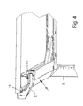
- Fig. 4 is merely indicated, for example, that on the truss profile 10 clamping elements 21 can be fastened, wherein a clamping head 22 engages in the channel, which is formed by the profile wall 12 and the turns 12a and 12b, as is apparent from Fig. 4 yields and which can serve for the attachment of additional elements on the multi-function table.
- These fixing elements 21 also have an engagement ridge 23 which engages in the joint 17, as is also the case Fig. 4 results.
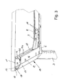
- mounting corners 6 and 6a are provided according to the invention, which can engage with engaging webs 24 in the free open ends of the respective in the corners of the converging profiles 10.
- These mounting corners are also equipped with integrally molded through sleeves 25, are provided in the fixing and threaded pins 26 in the free ends of the respectively to be mounted table legs 3 and 3a, can grip, such that during assembly and after insertion of the trapezoidal in plan view Montageeckwinkels 8 fixing screws 9 can engage in these threaded sleeves 26.
- the clamping screw 9 provided on the mounting corner 8 engaging tabs 27 are pressed into the rows of slots 18 and thus brace the respective table leg 3 against the mounting corner 6 and this in turn to the respective, forming the trusses hollow sections 10th
- Fig. 6 to 8 is shown as an example a situation in which two tabletops 2a and 2b are assembled to a table magnification.
- the identical parts with the above-described elements carry the same reference numerals, such as the Montageeckwinkel 8 with the respective mounting screw 9.
- the table according to Fig. 1 and 2 here carries one of the table legs to be mounted 3b in the head area a kind of short profile 10a, which can be inserted via coupling caps 28 and 29 Fixierkappen over the respective free ends of the longitudinal or transverse profiles can be fastened. If one side of the table is not provided with a corresponding table leg in the table top joint area, another short profile 10b is provided, as can be seen from Fig. 6 results.
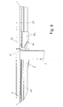
- the head is equipped with a support profile sheet 30 which can engage over the crossbeams, as can be seen from the Fig. 7 or 8 results.
- a mounting block 31 may be provided, which can engage with its webs in the shadow gap 17 under the table top and is thus used for fixing.
- the profile sheet 30 without table leg 3c in conjunction with the mounting block 31 can also serve to connect two tabletops ( Fig. 9 ), wherein a table top 2c is provided with corner brackets 6a without leg fittings.
- Fig. 1 is indicated by dashed lines, that the table top 2 can be provided with edge indentations 32, so that when two adjoining correspondingly shaped table tops, a passage opening is formed, for example, to allow wearer for a screen element.
Landscapes
- Engineering & Computer Science (AREA)
- General Engineering & Computer Science (AREA)
- Mechanical Engineering (AREA)
- Furniture Connections (AREA)
- Tables And Desks Characterized By Structural Shape (AREA)
- Connection Of Batteries Or Terminals (AREA)
- Computer And Data Communications (AREA)
- Drawing Aids And Blackboards (AREA)
Abstract
Description
- Die Erfindung richtet sich auf einen Bausatz zur Erzeugung eines Mehrfunktionen-Schreib- oder -Arbeitstisches der im Oberbegriff des Anspruches 1 angegebenen Gattung.
- Derartige Bausätze sind in sehr unterschiedlichen Gestaltungen bekannt. Um hier nur einige zu nennen, sei das Gebrauchsmuster
DE 20 2004 015 734 oder20 2006 016 327 der Anmelderin genannt. - Wesentlich bei den bekannten Lösungen ist, dass die die Füße aufnehmenden Bauteile nicht nur diese Funktion ausüben und die Funktion der Fixierung einer Tischplatte, sondern auch zusätzliche Funktionen auszuüben in der Lage sind.
- Aufgabe der vorliegenden Erfindung ist die Bereitstellung eines Bausatzes, der neben den oben erwähnten Eigenschaften sich durch konstruktiv einfache Elemente auszeichnet, die eine besondere Vielfältigkeit in der Nutzung bieten bei einfacher Montagemöglichkeit und großer Erweiterungsfähigkeit eines damit hergestellten Tischsystemes.
- Mit einem Bausatz der eingangs bezeichneten Art wird diese Aufgabe dadurch gelöst, dass die Traversen als Hohlprofile ausgebildet sind mit einer ersten Profilfläche zur Fixierung an der Unterseite der Tischplatte, einer zweiten dazu etwas senkrecht laufenden kürzeren Profilfläche, die in eine dritte, zur ersten Profilfläche parallelen kürzeren Profilfläche übergeht, einer vierten im stumpfen Winkel davon abgehenden Schrägfläche, die in eine fünfte kurze, zur zweiten Profilfläche parallelen Profilfläche mündet, die ihrerseits in die erste Profilfläche mündet.
- Mit der erfindungsgemäßen Gestaltung des Profiles wird zum einen eine große Stabilität erreicht, gleichzeitig ergibt sich optisch ein sehr schmales Profil, da die dem Betrachter zugewandte fünfte Profilfläche sehr schmal gestaltet werden kann. Ein mehrteiliges Unterschraubprofil ist in der
US 2 943 898 A dargestellt - Eine Ausgestaltung der Erfindung besteht darin, dass der Übergang der fünften Profilfläche zur ersten Profilfläche als rückgekröpfte Winkelfläche ausgebildet ist. Mit dieser Rückkröpfung wird zum einen unter der Tischplatte eine Art Schattenfuge erzeugt, gleichzeitig bietet der so gestaltete Rücksprung eine Eingriffsmöglichkeit für Stege an Fixierungselementen, die am Profil festgeklemmt werden können und zur Befestigung weiterer Elemente am Tisch dienen können, etwa Halter für Computerbildschirme, Halter für Lampenfüße, Halter für Telefonständer oder Halter für Abschirmwände gegenüber anderen Tischen u. dgl. mehr.
- Diesem Zweck dient auch eine weitere Ausgestaltung der Erfindung, die darin besteht, dass die zweite Profilfläche unter Bildung parallel zur ersten und dritten Fläche ausgerichteten Umkröpfungen in das Profilinnere zurückversetzt ausgebildet ist. Durch die dritte rückversetzte Profilfläche wird zum einen eine sehr hohe Stabilität des Profiles gewährleistet, gleichzeitig bilden die Umkröpfungen zusammen mit der Profilfläche eine optimale Führung für anzubringende Zusatzelemente, etwa von Fixiereckelementen für die Tischbeine, für Verlängerungselemente od. dgl.
- Zum Eingriff von Steg- oder Hakenflächen an Montageelementen kann, wie dies die Erfindung ebenfalls vorsieht, die rückgekröpfte Profilfläche wenigstens teilweise mit Schlitzen, insbesondere mit zwei parallelen Reihen von Schlitzen, zum Eingriff von Montagestegen von Zusatzelementen ausgerüstet sein.
- Auch die parallel zur Tischfläche und in der Gebrauchslage an der Unterseite der Tischplatte anliegende erste und dazu parallele dritte Profilfläche kann erfindungsgemäß mit Durchtrittsöffnungen ausgerüstet sein. Dies dient insbesondere der Möglichkeit, Fixierschrauben anzubringen, ohne dass die Erfindung auf diese Nutzungsmöglichkeit der Durchtrittsöffnungen beschränkt wäre.
- Die Erfindung sieht auch Montageeckwinkel für die Tischbeine vor, die mit Eingriffsstutzen in das Innere der die Quer- und Längstraversen bildenden Profile an deren freien Enden ausgerüstet sind, wobei derartige Montageeckwinkel in unterschiedlichen Gestaltungen im Stand der Technik vorbeschrieben sind. Die vorliegende Erfindung bietet mit der Gestaltung der Montagewinkel die Möglichkeit, diese, falls gewünscht, entsprechend optisch hervorzuheben, um dem so erzeugten Tisch eine zusätzliche Gestaltung aufzuprägen. Eine Tischbeineckverbindung zeigt beispielsweise die
US 9 964 404 A - Erfindungsgemäß kann vorgesehen sein, dass die Montageeckwinkel für die Tischbeine mit Eingriffsstutzen in das Innere der die Quer- und Längstraversen bildenden Profile an deren freien Enden ausgerüstet sind.
- Darüber hinaus kann erfindungsgemäß eine querschnittlich U-förmige, in Aufsicht etwa trapezförmige Fixierklammer vorgesehen sein zum Zusammenwirken mit dem Montageeckwinkel insbesondere zum Durchtritt einer Montageschraube od. dgl. zur Fixierung eines Tischbeines nach Durchtritt durch die Montageeckwinkel.
- Schließlich sieht die Erfindung auch vor, dass der querschnittlich etwa U-förmige Montagewinkel mit der Durchtrittsbohrung im U-Steg für die Montageschraube mit nach außen weisenden Eingriffslaschen an den Rändern der U-Schenkel zum Eingriff in die Ausnehmungen in der zweiten rückgekröpften Profilwand ausgerüstet ist.
- Weitere Einzelheiten, Merkmale und Vorteile der Erfindung ergeben sich aufgrund der nachfolgenden Beschreibung sowie anhand der Zeichnung. Diese zeigt in
- Fig. 1
- die räumliche Darstellung eines Tisches nach der Erfindung,
- Fig. 2
- die räumliche Unteransicht eines Tisches nach der Erfindung,
- Fig. 3
- eine räumliche Detailansicht in Unteransicht einer Tischecke,
- Fig. 4
- die gleiche Darstellung wie in
Fig. 3 mit zusätzlichem Klemmelement, - Fig. 5
- eine Tischecke in Unteransicht mit Montageecken und zwei querschnittlich unterschiedlichen Tischbeinen,
- Fig. 6 bis 8
- in Unteransicht zwei Tischbereiche in unterschiedlichen Montagezuständen sowie in
- Fig. 9
- Seiten-Detailansicht der Kopplung zweier Tischplatten.
- Der erfindungsgemäße Bausatz dient zur Erzeugung eines Mehrfunktionen-Schreibtisches, allgemein mit 1 bezeichnet, dessen wesentliche Elemente in einer Tischplatte 2, vier Tischbeine 3 in der einfachsten Ausgestaltung, wie sie in
Fig. 1 dargestellt ist, sowie aus unter der Tischplatte 2 montierten Längstraversen 4 und Quertraversen 5 bestehen, wobei zur Montage der Tischplatte 3 an den Traversenenden Montageecken, allgemein mit 6 bezeichnet, vorgesehen sind. - Wie sich aus
Fig. 1 ergibt, können die Tischbeine 3 höhenverstellbar sein. Dabei taucht ein in der Montageecke 6 befestigtes Beinelement 3a in ein Hülsenelement 3b ein, wobei die beiden Elemente über eine Stellschraube 7 aneinander fixierbar sind. Hierauf kommt es aber ebenso wenig an, wie auf die Querschnittsformen der Tischbeine 3. Diese können neben der inFig. 1 dargestellten eckigen Form auch eine runde Form aufweisen, wie sich dies z.B. ausFig. 5 ergibt, sie können aber auch elliptisch sein oder Mischformen haben. - Wie sich aus der Unteransicht der
Fig. 2 unter die Tischplatte 2 ergibt, werden die Tischbeine 3 mittels in Aufsicht trapezförmigen Fixierklammern 8 mit Hilfe von Spannschrauben 9 befestigt, deren genaue Positionierung weiter unten näher beschrieben ist. - Ein wesentliches Element des erfindungsgemäßen Bausatzes stellt das Profil dar, aus dem die Quer- und Längstraversen 4 und 5 gebildet sind. Dieses Profil ist im Querschnitt vergrößert in
Fig. 3 dargestellt und allgemein mit der Bezugsziffer 10 bezeichnet. - Dieses Profil 10 setzt sich aus unterschiedlichen Profilflächen zusammen, wobei eine erste Profilfläche 11 vorgesehen ist, die sich in der Gebrauchslage an die Unterseite der Tischplatte 2 anlegt. An diese Profilfläche 11 schließt sich im rechten Winkel eine zweite kürzere Profilfläche 12 an, die in eine dritte Profilfläche 13 übergeht, die wiederum parallel zur ersten Profilfläche 11 ausgerüstet ist. Die vierte Profilfläche 14 verläuft in einem stumpfen Winkel von der Profilfläche 13 in eine zur zweiten Profilfläche 12 parallele, kürzere Profilfläche 15 ein, die ihrerseits über eine rückgekröpfte Winkelfläche 16 in die erste Profilfläche 11 übergeht. Durch die rückgekröpfte Winkelfläche 16 bildet sich unterhalb der Tischplatte 2 eine Art Schattenfuge 17, die auch zur Aufnahme von Stegen an Klemmelementen od. dgl. einsetzbar ist.
- Ein wesentliches Gestaltungsmerkmal des Hohlprofiles 10 besteht darin, dass die zweite Profilfläche 12, die zur ersten senkrecht ausgebildet ist, ihrerseits in das Profilinnere zurückversetzt ist, so dass sich zwei Umkröpfungen 12a und 12b ergeben, die einen Kanal bilden, in den Elemente eingreifen können bei gleichzeitiger Sicherung und Führung dieser Elemente.
- Um Fixierungen zu ermöglichen, ist die Fläche 12 mit Schlitzen 18, im dargestellten Beispiel der
Fig. 5 mit zwei parallelen Reihen von Schlitzen 18, ausgerüstet, in die Stege od. dgl. von Fixierklammern 8 eingreifen können, wie sich dies beispielsweise ausFig. 3 ergibt. Die Fixierschraube 9 durchsetzt die Fixierklammer 8 und greift nach Durchtritt des Eckwinkels im Gewinde an dem jeweiligen Tischbein 3 ein, wie dies weiter unten zuFig. 5 näher beschrieben ist. - Im Profil 10 können auch weitere Durchgangsbohrungen 19 bzw. 20 vorgesehen sein, die z.B. zum Durchtritt von Befestigungsschrauben dienen bzw. der Werkzeuge, die diese Schrauben betätigen.
- In
Fig. 4 ist lediglich beispielsweise angedeutet, dass am Traversenprofil 10 Spannelemente 21 befestigbar sind, wobei ein Spannkopf 22 in die Rinne eingreift, die von der Profilwand 12 und den Umkröpfungen 12a und 12b gebildet wird, wie sich dies ausFig. 4 ergibt und die zur Befestigung von Zusatzelementen am Mehrfunktionentisch dienen können. Diese Fixierelemente 21 weisen auch einen Eingriffssteg 23 auf, der in die Fuge 17 eingreift, wie sich dies auch ausFig. 4 ergibt. - Wie in
Fig. 5 dargestellt, sind erfindungsgemäß Montageecken 6 bzw. 6a vorgesehen, die mit Eingriffsstegen 24 in die freien offenen Enden der jeweilig in den Ecken der zusammenlaufenden Profile 10 eingreifen können. Diese Montageecken sind auch mit einstückig angeformten Durchtrittshülsen 25 ausgestattet, in die Fixier- und Gewindezapfen 26 in den freien Enden der jeweilig zu montierenden Tischbeine 3 bzw. 3a vorgesehen sind, greifen können, derart, dass bei der Montage und nach Einsetzen des in Aufsicht trapezförmigen Montageeckwinkels 8 Fixierschrauben 9 in diese Gewindehülsen 26 eingreifen können. Bei Anziehen der Spannschraube 9 werden die an den Montageeckwinkeln 8 vorgesehenen Eingriffslaschen 27 in die Schlitzreihen 18 eingepresst und verspannen damit das jeweilige Tischbein 3 gegen die Montageecke 6 und diese wiederum an den jeweiligen, die Traversen bildenden Hohlprofilen 10. - In den
Fig. 6 bis 8 ist als Beispiel eine Situation dargestellt, in der zwei Tischplatten 2a und 2b zu einer Tischvergrößerung zusammengefügt werden. Die mit den vorbeschriebenen Elementen identischen Teile tragen das gleiche Bezugszeichen, so beispielsweise die Montageeckwinkel 8 mit der jeweiligen Montageschraube 9. Zum Unterschied der Ausführungsform des Tisches gemäßFig. 1 und2 trägt hier eines der zu montierenden Tischbeine 3b im Kopfbereich eine Art Kurzprofil 10a, das über Kupplungskappen 28 bzw. Fixierkappen 29 über den jeweiligen freien Enden der Längs- bzw. Querprofile einsteckbar sind, befestigbar ist. Wird eine Seite des Tisches nicht mit einem entsprechenden Tischbein im Tischplattenfugenbereich versehen, ist ein weiteres Kurzprofil 10b vorgesehen, wie sich dies ausFig. 6 ergibt. - Aus dieser Figur ergibt sich auch, dass an den Quertraversen auch ein Tischbein, mit 3c bezeichnet, befestigbar ist, dessen Kopf mit einem Tragprofilblech 30 ausgerüstet ist, das die Quertraversen übergreifen kann, wie sich dies aus den
Fig. 7 bzw. 8 ergibt. Dabei kann ein Montageblock 31 vorgesehen sein, der mit seinen Stegen in die Schattenfuge 17 unter der Tischplatte greifen kann und so zur Fixierung herangezogen wird. Das Profilblech 30 ohne Tischbein 3c in Verbindung mit dem Montageblock 31 kann auch zur Verbindung zweier Tischplatten dienen (Fig. 9 ), wobei eine Tischplatte 2c mit Eckwinkeln 6a ohne Beinaufnahmen versehen ist. - Natürlich ist das beschriebene Ausführungsbeispiel der Erfindung noch in vielfacher Hinsicht abzuändern, ohne den Grundgedanken zu verlassen. Mit der Erfindung können unterschiedliche Tischkonfigurationen erzeugt werden, ob rechtwinklig zueinander z.B. im Winkel von 120°, wenn die Montageecken 6 entsprechend gestaltet sind. Es können Tischaufbauten an den Profilen befestigt werden ebenso wie Halterungen oder Ständer für Computer, Drucker oder dgl..
- In
Fig. 1 ist gestrichelt angedeutet, dass die Tischplatte 2 mit randseitigen Einbuchtungen 32 versehen sein kann, so dass bei zwei aneinander anstoßenden entsprechend gestalteten Tischplatten eine Durchtrittsöffnung entsteht, um z.B. Träger für ein Sichtschutzelement hindurchtreten zu lassen.
Claims (8)
- Bausatz zur Erzeugung eines Mehrfunktionen-Schreib- oder -Arbeitstisches mit einer Tischplatte, randseitig unter der Tischplatte befestigten Quer- und Längstraversen sowie an den stirnseitigen Enden der Traversen über Montageecken befestigten Tischbeinen,
dadurch gekennzeichnet,
dass die Traversen als Hohlprofile (10) ausgebildet sind mit einer ersten Profilfläche (11) zur Fixierung an der Unterseite der Tischplatte (2), einer zweiten dazu etwas senkrecht verlaufenden kürzeren Profilfläche (11), die in eine dritte zur ersten Profilfläche (10) parallelen kürzeren Profilfläche (13) übergeht, einer vierten im stumpfen Winkel davon abgehenden Schrägfläche (14), die in eine fünfte kurze, zur zweiten Profilfläche (12) parallelen Profilfläche (15) mündet, die ihrerseits in die erste Profilfläche (11) mündet. - Bausatz nach Anspruch 1,
dadurch gekennzeichnet,
dass der Übergang der fünften Profilfläche (15) zur ersten Profilfläche (11) als rückgekröpfte Winkelfläche (16) ausgebildet ist. - Bausatz nach Anspruch 1 und 2,
dadurch gekennzeichnet,
dass die zweite Profilfläche (12) unter Bildung parallel zur ersten und dritten Fläche ausgerichteten Umkröpfungen (12a,12b) in das Profilinnere zurückversetzt ausgebildet ist. - Bausatz nach einem der vorangehenden Ansprüche,
dadurch gekennzeichnet,
dass die rückgekröpfte Profilfläche (12) wenigstens teilweise mit Schlitzen (18) insbesondere mit zwei parallelen Reihen von Schlitzen (18) zum Eingriff von Montagestegen (27) von Zusatzelementen ausgerüstet ist. - Bausatz nach einem der vorangehenden Ansprüche,
dadurch gekennzeichnet,
dass die parallel zur Tischfläche (2) ausgerichtete erste und dazu parallele dritte Profilfläche (11,13) wenigstens bereichsweise mit Durchtrittsöffnungen (19, 20) ausgerüstet ist. - Bausatz nach einem der vorangehenden Ansprüche,
gekennzeichnet durch
Montageeckwinkel (6) für die Tischbeine (3) mit Eingriffsstutzen (24) in das Innere der die Quer- und Längstraversen bildenden Profile (10) an deren freien Enden ausgerüstet sind. - Bausatz nach einem der vorangehenden Ansprüche,
gekennzeichnet durch
eine querschnittlich U-förmige, in Aufsicht etwa trapezförmige Fixierklammer (8) zum Zusammenwirken mit dem Montageeckwinkel (6) insbesondere zum Durchtritt einer Montageschraube (9) od. dgl. zur Fixierung eines Tischbeines (3) nach Durchtritt durch die Montageeckwinkel (6). - Bausatz nach einem der vorangehenden Ansprüche,
dadurch gekennzeichnet,
dass der querschnittlich etwa U-förmige Montageeckwinkel (8) mit der Durchtrittsbohrung im U-Steg für die Montageschraube (9) mit nach außen weisenden Eingriffslaschen (27) an den Rändern der U-Schenkel zum Eingriff in die Ausnehmungen (18) in der zweiten rückgekröpften Profilfläche (12) ausgerüstet ist.
Applications Claiming Priority (1)
| Application Number | Priority Date | Filing Date | Title |
|---|---|---|---|
| DE202008008239U DE202008008239U1 (de) | 2008-06-19 | 2008-06-19 | Bausatz zur Erzeugung eines Mehrfunktionen-Schreib- oder -Arbeitstisches |
Publications (3)
| Publication Number | Publication Date |
|---|---|
| EP2138069A2 true EP2138069A2 (de) | 2009-12-30 |
| EP2138069A3 EP2138069A3 (de) | 2010-01-20 |
| EP2138069B1 EP2138069B1 (de) | 2010-10-13 |
Family
ID=41254306
Family Applications (1)
| Application Number | Title | Priority Date | Filing Date |
|---|---|---|---|
| EP09007647A Active EP2138069B1 (de) | 2008-06-19 | 2009-06-10 | Bausatz zur Erzeugung eines Mehrfunktionen-Schreib- oder -Arbeitstisches |
Country Status (3)
| Country | Link |
|---|---|
| EP (1) | EP2138069B1 (de) |
| AT (1) | ATE484683T1 (de) |
| DE (2) | DE202008008239U1 (de) |
Cited By (1)
| Publication number | Priority date | Publication date | Assignee | Title |
|---|---|---|---|---|
| CN108001844A (zh) * | 2017-12-26 | 2018-05-08 | 中山市铁韵五金制品有限公司 | 用于台支撑架上的多向v型夹紧结构 |
Families Citing this family (3)
| Publication number | Priority date | Publication date | Assignee | Title |
|---|---|---|---|---|
| DE202012104001U1 (de) | 2012-10-18 | 2014-01-20 | Sedus Systems Gmbh | Tisch, insbesondere Schreib- oder Arbeitstisch |
| JP6647219B2 (ja) | 2014-05-26 | 2020-02-14 | リナック エー/エス | 家具用支持フレーム |
| DE202014104982U1 (de) | 2014-10-20 | 2016-01-21 | Sedus Systems Gmbh | Bausatz zur Erzeugung eines Tisches, insbesondere eines Arbeits- oder Schreibtisches |
Citations (4)
| Publication number | Priority date | Publication date | Assignee | Title |
|---|---|---|---|---|
| US2943898A (en) | 1958-09-04 | 1960-07-05 | Lyon Metal Products Inc | Sheet metal table having hollow end panels supporting the table top |
| US3964404A (en) | 1975-05-09 | 1976-06-22 | American Hospital Supply Corporation | Shelf and corner post assembly |
| DE202004015734U1 (de) | 2004-10-12 | 2005-09-22 | GESIKA Büromöbelwerk GmbH | Bausatz zur Erzeugung eines Büroarbeitsplatzes |
| DE202006016327U1 (de) | 2006-10-12 | 2008-02-21 | Rieber Gmbh & Co. Kg | Speisenwarmhalte- und Speisengargerät |
Family Cites Families (4)
| Publication number | Priority date | Publication date | Assignee | Title |
|---|---|---|---|---|
| US3420484A (en) * | 1967-03-06 | 1969-01-07 | Gen Metal Products Co | Corner construction for knock-down tables |
| GB1441547A (en) * | 1974-05-08 | 1976-07-07 | Sebel Ltd | Metal table frames |
| GB2129903A (en) * | 1982-11-06 | 1984-05-23 | Marc Udo Schmoelz | Construction system |
| IT1310997B1 (it) * | 1999-02-23 | 2002-02-27 | Angelo Odorico | Giunto di assemblaggio per telai di mobili. |
-
2008
- 2008-06-19 DE DE202008008239U patent/DE202008008239U1/de not_active Expired - Lifetime
-
2009
- 2009-06-10 AT AT09007647T patent/ATE484683T1/de active
- 2009-06-10 EP EP09007647A patent/EP2138069B1/de active Active
- 2009-06-10 DE DE502009000127T patent/DE502009000127D1/de active Active
Patent Citations (4)
| Publication number | Priority date | Publication date | Assignee | Title |
|---|---|---|---|---|
| US2943898A (en) | 1958-09-04 | 1960-07-05 | Lyon Metal Products Inc | Sheet metal table having hollow end panels supporting the table top |
| US3964404A (en) | 1975-05-09 | 1976-06-22 | American Hospital Supply Corporation | Shelf and corner post assembly |
| DE202004015734U1 (de) | 2004-10-12 | 2005-09-22 | GESIKA Büromöbelwerk GmbH | Bausatz zur Erzeugung eines Büroarbeitsplatzes |
| DE202006016327U1 (de) | 2006-10-12 | 2008-02-21 | Rieber Gmbh & Co. Kg | Speisenwarmhalte- und Speisengargerät |
Cited By (1)
| Publication number | Priority date | Publication date | Assignee | Title |
|---|---|---|---|---|
| CN108001844A (zh) * | 2017-12-26 | 2018-05-08 | 中山市铁韵五金制品有限公司 | 用于台支撑架上的多向v型夹紧结构 |
Also Published As
| Publication number | Publication date |
|---|---|
| ATE484683T1 (de) | 2010-10-15 |
| EP2138069B1 (de) | 2010-10-13 |
| DE502009000127D1 (de) | 2010-11-25 |
| EP2138069A3 (de) | 2010-01-20 |
| DE202008008239U1 (de) | 2009-10-29 |
Similar Documents
| Publication | Publication Date | Title |
|---|---|---|
| DE102006025036B4 (de) | Befestigungsvorrichtung zum Befestigen eines oder zweier benachbarter Bauteile, insbesondere Solarzellenmodule, an einer eine T-förmige Nut aufweisenden Profilschiene | |
| DE102019219588A1 (de) | Befestigungsvorrichtung und Tisch mit einer solchen Befestigungsvorrichtung | |
| EP2138069B1 (de) | Bausatz zur Erzeugung eines Mehrfunktionen-Schreib- oder -Arbeitstisches | |
| EP2207974A1 (de) | Verbindungsbeschlag und montageanordnung | |
| DE202014102469U1 (de) | Befestigungseinrichtung für einen Holm oder eine Leiste an einem C-Profil | |
| DE102017005297B4 (de) | Einstellbarer Beschlag | |
| AT520822B1 (de) | Schubladenseitenwand | |
| DE102011101759B4 (de) | Vorrichtung zur Montage eines elektrischen Bauteils, insbesondere eines Schalters, an einer Montageplatte | |
| EP2250930A1 (de) | Versorgungssystem zum Bereitstellen einer Medienversorgung | |
| EP2446777B1 (de) | Knotenbauteil für ein Gestell für einen Tisch, Gestell für einen Tisch sowie Tisch | |
| DE202004012107U1 (de) | Ausrichtvorrichtung und/oder Aufhängevorrichtungssystem | |
| EP1134170A1 (de) | Modulartig zusammensetzbare Struktur für Lagerregale | |
| DE202012009700U1 (de) | Dachhaken | |
| AT508129B1 (de) | Befestigungsvorrichtung für einen möbelbeschlag | |
| DE202016003333U1 (de) | Befestigungssystem | |
| DE102007011650B3 (de) | Baugruppe mit zwei in gegenseitigem Abstand angeordneten Bauteilen | |
| DE60313024T2 (de) | Versetzbare trennwand | |
| EP3007157B1 (de) | Haltevorrichtung | |
| EP4114150A1 (de) | Erweiterungsbausatz | |
| DE102005013086B4 (de) | System, bestehend aus einer Sockelblende und einer Abdeckung | |
| DE202022107179U1 (de) | Untergestell und Tisch | |
| EP2065521B1 (de) | Befestigungssystem zur Befestigung eines Geräteeinsatzes in einer Einbauöffnung einer Arbeitsplatte. | |
| DE102012001097B3 (de) | Sockeleckstück für die Einhandmontage an einem Schaltschrank | |
| EP3622854A1 (de) | Möbel mit einem rahmengestell aus über einen eckverbinder verbundenen rohrrahmen | |
| EP4190492A1 (de) | Werkbankadaptersystem für werkbänke mit lochraster |
Legal Events
| Date | Code | Title | Description |
|---|---|---|---|
| PUAI | Public reference made under article 153(3) epc to a published international application that has entered the european phase |
Free format text: ORIGINAL CODE: 0009012 |
|
| PUAL | Search report despatched |
Free format text: ORIGINAL CODE: 0009013 |
|
| AK | Designated contracting states |
Kind code of ref document: A2 Designated state(s): AT BE BG CH CY CZ DE DK EE ES FI FR GB GR HR HU IE IS IT LI LT LU LV MC MK MT NL NO PL PT RO SE SI SK TR |
|
| AK | Designated contracting states |
Kind code of ref document: A3 Designated state(s): AT BE BG CH CY CZ DE DK EE ES FI FR GB GR HR HU IE IS IT LI LT LU LV MC MK MT NL NO PL PT RO SE SI SK TR |
|
| AX | Request for extension of the european patent |
Extension state: AL BA RS |
|
| RIC1 | Information provided on ipc code assigned before grant |
Ipc: A47B 9/14 20060101ALI20091216BHEP Ipc: A47B 13/06 20060101ALI20091216BHEP Ipc: F16B 12/52 20060101AFI20091216BHEP |
|
| 17P | Request for examination filed |
Effective date: 20100323 |
|
| GRAP | Despatch of communication of intention to grant a patent |
Free format text: ORIGINAL CODE: EPIDOSNIGR1 |
|
| GRAS | Grant fee paid |
Free format text: ORIGINAL CODE: EPIDOSNIGR3 |
|
| GRAA | (expected) grant |
Free format text: ORIGINAL CODE: 0009210 |
|
| AK | Designated contracting states |
Kind code of ref document: B1 Designated state(s): AT BE BG CH CY CZ DE DK EE ES FI FR GB GR HR HU IE IS IT LI LT LU LV MC MK MT NL NO PL PT RO SE SI SK TR |
|
| REG | Reference to a national code |
Ref country code: GB Ref legal event code: FG4D Free format text: NOT ENGLISH |
|
| REG | Reference to a national code |
Ref country code: CH Ref legal event code: EP |
|
| REG | Reference to a national code |
Ref country code: CH Ref legal event code: NV Representative=s name: BOVARD AG PATENTANWAELTE |
|
| REG | Reference to a national code |
Ref country code: IE Ref legal event code: FG4D Free format text: LANGUAGE OF EP DOCUMENT: GERMAN |
|
| REF | Corresponds to: |
Ref document number: 502009000127 Country of ref document: DE Date of ref document: 20101125 Kind code of ref document: P |
|
| REG | Reference to a national code |
Ref country code: NL Ref legal event code: VDEP Effective date: 20101013 |
|
| LTIE | Lt: invalidation of european patent or patent extension |
Effective date: 20101013 |
|
| REG | Reference to a national code |
Ref country code: CH Ref legal event code: PFA Owner name: SEDUS SYSTEMS GMBH Free format text: SEDUS SYSTEMS GMBH#SALZKOTTENER STRASSE 65#59590 GESEKE (DE) -TRANSFER TO- SEDUS SYSTEMS GMBH#SALZKOTTENER STRASSE 65#59590 GESEKE (DE) |
|
| PG25 | Lapsed in a contracting state [announced via postgrant information from national office to epo] |
Ref country code: NO Free format text: LAPSE BECAUSE OF FAILURE TO SUBMIT A TRANSLATION OF THE DESCRIPTION OR TO PAY THE FEE WITHIN THE PRESCRIBED TIME-LIMIT Effective date: 20110113 Ref country code: LT Free format text: LAPSE BECAUSE OF FAILURE TO SUBMIT A TRANSLATION OF THE DESCRIPTION OR TO PAY THE FEE WITHIN THE PRESCRIBED TIME-LIMIT Effective date: 20101013 |
|
| REG | Reference to a national code |
Ref country code: IE Ref legal event code: FD4D |
|
| PG25 | Lapsed in a contracting state [announced via postgrant information from national office to epo] |
Ref country code: HR Free format text: LAPSE BECAUSE OF FAILURE TO SUBMIT A TRANSLATION OF THE DESCRIPTION OR TO PAY THE FEE WITHIN THE PRESCRIBED TIME-LIMIT Effective date: 20101013 Ref country code: FI Free format text: LAPSE BECAUSE OF FAILURE TO SUBMIT A TRANSLATION OF THE DESCRIPTION OR TO PAY THE FEE WITHIN THE PRESCRIBED TIME-LIMIT Effective date: 20101013 Ref country code: SE Free format text: LAPSE BECAUSE OF FAILURE TO SUBMIT A TRANSLATION OF THE DESCRIPTION OR TO PAY THE FEE WITHIN THE PRESCRIBED TIME-LIMIT Effective date: 20101013 Ref country code: BG Free format text: LAPSE BECAUSE OF FAILURE TO SUBMIT A TRANSLATION OF THE DESCRIPTION OR TO PAY THE FEE WITHIN THE PRESCRIBED TIME-LIMIT Effective date: 20110113 Ref country code: LV Free format text: LAPSE BECAUSE OF FAILURE TO SUBMIT A TRANSLATION OF THE DESCRIPTION OR TO PAY THE FEE WITHIN THE PRESCRIBED TIME-LIMIT Effective date: 20101013 Ref country code: NL Free format text: LAPSE BECAUSE OF FAILURE TO SUBMIT A TRANSLATION OF THE DESCRIPTION OR TO PAY THE FEE WITHIN THE PRESCRIBED TIME-LIMIT Effective date: 20101013 Ref country code: SI Free format text: LAPSE BECAUSE OF FAILURE TO SUBMIT A TRANSLATION OF THE DESCRIPTION OR TO PAY THE FEE WITHIN THE PRESCRIBED TIME-LIMIT Effective date: 20101013 Ref country code: IS Free format text: LAPSE BECAUSE OF FAILURE TO SUBMIT A TRANSLATION OF THE DESCRIPTION OR TO PAY THE FEE WITHIN THE PRESCRIBED TIME-LIMIT Effective date: 20110213 Ref country code: PT Free format text: LAPSE BECAUSE OF FAILURE TO SUBMIT A TRANSLATION OF THE DESCRIPTION OR TO PAY THE FEE WITHIN THE PRESCRIBED TIME-LIMIT Effective date: 20110214 |
|
| PG25 | Lapsed in a contracting state [announced via postgrant information from national office to epo] |
Ref country code: GR Free format text: LAPSE BECAUSE OF FAILURE TO SUBMIT A TRANSLATION OF THE DESCRIPTION OR TO PAY THE FEE WITHIN THE PRESCRIBED TIME-LIMIT Effective date: 20110114 |
|
| PG25 | Lapsed in a contracting state [announced via postgrant information from national office to epo] |
Ref country code: ES Free format text: LAPSE BECAUSE OF FAILURE TO SUBMIT A TRANSLATION OF THE DESCRIPTION OR TO PAY THE FEE WITHIN THE PRESCRIBED TIME-LIMIT Effective date: 20110124 Ref country code: EE Free format text: LAPSE BECAUSE OF FAILURE TO SUBMIT A TRANSLATION OF THE DESCRIPTION OR TO PAY THE FEE WITHIN THE PRESCRIBED TIME-LIMIT Effective date: 20101013 Ref country code: CZ Free format text: LAPSE BECAUSE OF FAILURE TO SUBMIT A TRANSLATION OF THE DESCRIPTION OR TO PAY THE FEE WITHIN THE PRESCRIBED TIME-LIMIT Effective date: 20101013 Ref country code: IE Free format text: LAPSE BECAUSE OF FAILURE TO SUBMIT A TRANSLATION OF THE DESCRIPTION OR TO PAY THE FEE WITHIN THE PRESCRIBED TIME-LIMIT Effective date: 20101013 |
|
| PLBE | No opposition filed within time limit |
Free format text: ORIGINAL CODE: 0009261 |
|
| STAA | Information on the status of an ep patent application or granted ep patent |
Free format text: STATUS: NO OPPOSITION FILED WITHIN TIME LIMIT |
|
| PG25 | Lapsed in a contracting state [announced via postgrant information from national office to epo] |
Ref country code: RO Free format text: LAPSE BECAUSE OF FAILURE TO SUBMIT A TRANSLATION OF THE DESCRIPTION OR TO PAY THE FEE WITHIN THE PRESCRIBED TIME-LIMIT Effective date: 20101013 Ref country code: SK Free format text: LAPSE BECAUSE OF FAILURE TO SUBMIT A TRANSLATION OF THE DESCRIPTION OR TO PAY THE FEE WITHIN THE PRESCRIBED TIME-LIMIT Effective date: 20101013 Ref country code: DK Free format text: LAPSE BECAUSE OF FAILURE TO SUBMIT A TRANSLATION OF THE DESCRIPTION OR TO PAY THE FEE WITHIN THE PRESCRIBED TIME-LIMIT Effective date: 20101013 Ref country code: PL Free format text: LAPSE BECAUSE OF FAILURE TO SUBMIT A TRANSLATION OF THE DESCRIPTION OR TO PAY THE FEE WITHIN THE PRESCRIBED TIME-LIMIT Effective date: 20101013 |
|
| 26N | No opposition filed |
Effective date: 20110714 |
|
| REG | Reference to a national code |
Ref country code: DE Ref legal event code: R097 Ref document number: 502009000127 Country of ref document: DE Effective date: 20110714 |
|
| PG25 | Lapsed in a contracting state [announced via postgrant information from national office to epo] |
Ref country code: IT Free format text: LAPSE BECAUSE OF FAILURE TO SUBMIT A TRANSLATION OF THE DESCRIPTION OR TO PAY THE FEE WITHIN THE PRESCRIBED TIME-LIMIT Effective date: 20101013 Ref country code: MT Free format text: LAPSE BECAUSE OF FAILURE TO SUBMIT A TRANSLATION OF THE DESCRIPTION OR TO PAY THE FEE WITHIN THE PRESCRIBED TIME-LIMIT Effective date: 20101013 |
|
| BERE | Be: lapsed |
Owner name: SEDUS SYSTEMS G.M.B.H. Effective date: 20110630 |
|
| PG25 | Lapsed in a contracting state [announced via postgrant information from national office to epo] |
Ref country code: BE Free format text: LAPSE BECAUSE OF NON-PAYMENT OF DUE FEES Effective date: 20110630 |
|
| PG25 | Lapsed in a contracting state [announced via postgrant information from national office to epo] |
Ref country code: MK Free format text: LAPSE BECAUSE OF FAILURE TO SUBMIT A TRANSLATION OF THE DESCRIPTION OR TO PAY THE FEE WITHIN THE PRESCRIBED TIME-LIMIT Effective date: 20101013 |
|
| PG25 | Lapsed in a contracting state [announced via postgrant information from national office to epo] |
Ref country code: MC Free format text: LAPSE BECAUSE OF NON-PAYMENT OF DUE FEES Effective date: 20110630 |
|
| PG25 | Lapsed in a contracting state [announced via postgrant information from national office to epo] |
Ref country code: LU Free format text: LAPSE BECAUSE OF NON-PAYMENT OF DUE FEES Effective date: 20110610 Ref country code: CY Free format text: LAPSE BECAUSE OF EXPIRATION OF PROTECTION Effective date: 20101013 |
|
| PG25 | Lapsed in a contracting state [announced via postgrant information from national office to epo] |
Ref country code: TR Free format text: LAPSE BECAUSE OF FAILURE TO SUBMIT A TRANSLATION OF THE DESCRIPTION OR TO PAY THE FEE WITHIN THE PRESCRIBED TIME-LIMIT Effective date: 20101013 |
|
| PG25 | Lapsed in a contracting state [announced via postgrant information from national office to epo] |
Ref country code: HU Free format text: LAPSE BECAUSE OF FAILURE TO SUBMIT A TRANSLATION OF THE DESCRIPTION OR TO PAY THE FEE WITHIN THE PRESCRIBED TIME-LIMIT Effective date: 20101013 |
|
| REG | Reference to a national code |
Ref country code: FR Ref legal event code: PLFP Year of fee payment: 7 |
|
| REG | Reference to a national code |
Ref country code: FR Ref legal event code: PLFP Year of fee payment: 8 |
|
| REG | Reference to a national code |
Ref country code: FR Ref legal event code: PLFP Year of fee payment: 9 |
|
| REG | Reference to a national code |
Ref country code: FR Ref legal event code: PLFP Year of fee payment: 10 |
|
| PGFP | Annual fee paid to national office [announced via postgrant information from national office to epo] |
Ref country code: FR Payment date: 20230621 Year of fee payment: 15 Ref country code: DE Payment date: 20230316 Year of fee payment: 15 |
|
| PGFP | Annual fee paid to national office [announced via postgrant information from national office to epo] |
Ref country code: AT Payment date: 20230616 Year of fee payment: 15 |
|
| PGFP | Annual fee paid to national office [announced via postgrant information from national office to epo] |
Ref country code: GB Payment date: 20230622 Year of fee payment: 15 Ref country code: CH Payment date: 20230702 Year of fee payment: 15 |