EP2136168A1 - Kondensator eines Kühlgeräts und Kühlgerät damit - Google Patents
Kondensator eines Kühlgeräts und Kühlgerät damit Download PDFInfo
- Publication number
- EP2136168A1 EP2136168A1 EP08158685A EP08158685A EP2136168A1 EP 2136168 A1 EP2136168 A1 EP 2136168A1 EP 08158685 A EP08158685 A EP 08158685A EP 08158685 A EP08158685 A EP 08158685A EP 2136168 A1 EP2136168 A1 EP 2136168A1
- Authority
- EP
- European Patent Office
- Prior art keywords
- condenser
- compressor
- cooling apparatus
- cooling
- cabinet
- Prior art date
- Legal status (The legal status is an assumption and is not a legal conclusion. Google has not performed a legal analysis and makes no representation as to the accuracy of the status listed.)
- Granted
Links
- 238000001816 cooling Methods 0.000 title claims abstract description 67
- 238000003860 storage Methods 0.000 claims abstract description 11
- XLYOFNOQVPJJNP-UHFFFAOYSA-N water Substances O XLYOFNOQVPJJNP-UHFFFAOYSA-N 0.000 claims description 11
- 239000002826 coolant Substances 0.000 description 15
- 238000004519 manufacturing process Methods 0.000 description 8
- 239000002184 metal Substances 0.000 description 5
- 229910000831 Steel Inorganic materials 0.000 description 4
- 239000010959 steel Substances 0.000 description 4
- 235000013361 beverage Nutrition 0.000 description 3
- 230000003247 decreasing effect Effects 0.000 description 2
- 238000001704 evaporation Methods 0.000 description 2
- 230000008020 evaporation Effects 0.000 description 2
- 235000013305 food Nutrition 0.000 description 2
- 239000007788 liquid Substances 0.000 description 2
- 238000003466 welding Methods 0.000 description 2
- 238000005452 bending Methods 0.000 description 1
- 238000004891 communication Methods 0.000 description 1
- 238000010276 construction Methods 0.000 description 1
- 235000013365 dairy product Nutrition 0.000 description 1
- 235000013399 edible fruits Nutrition 0.000 description 1
- 239000012530 fluid Substances 0.000 description 1
- 239000012774 insulation material Substances 0.000 description 1
- 230000007774 longterm Effects 0.000 description 1
- 238000007726 management method Methods 0.000 description 1
- 235000013372 meat Nutrition 0.000 description 1
- 238000012986 modification Methods 0.000 description 1
- 230000004048 modification Effects 0.000 description 1
- 239000002991 molded plastic Substances 0.000 description 1
- 239000004033 plastic Substances 0.000 description 1
- 230000003014 reinforcing effect Effects 0.000 description 1
- 238000005728 strengthening Methods 0.000 description 1
- 235000013311 vegetables Nutrition 0.000 description 1
- 238000004804 winding Methods 0.000 description 1
Images

Classifications
-
- F—MECHANICAL ENGINEERING; LIGHTING; HEATING; WEAPONS; BLASTING
- F25—REFRIGERATION OR COOLING; COMBINED HEATING AND REFRIGERATION SYSTEMS; HEAT PUMP SYSTEMS; MANUFACTURE OR STORAGE OF ICE; LIQUEFACTION SOLIDIFICATION OF GASES
- F25D—REFRIGERATORS; COLD ROOMS; ICE-BOXES; COOLING OR FREEZING APPARATUS NOT OTHERWISE PROVIDED FOR
- F25D19/00—Arrangement or mounting of refrigeration units with respect to devices or objects to be refrigerated, e.g. infrared detectors
-
- F—MECHANICAL ENGINEERING; LIGHTING; HEATING; WEAPONS; BLASTING
- F25—REFRIGERATION OR COOLING; COMBINED HEATING AND REFRIGERATION SYSTEMS; HEAT PUMP SYSTEMS; MANUFACTURE OR STORAGE OF ICE; LIQUEFACTION SOLIDIFICATION OF GASES
- F25D—REFRIGERATORS; COLD ROOMS; ICE-BOXES; COOLING OR FREEZING APPARATUS NOT OTHERWISE PROVIDED FOR
- F25D23/00—General constructional features
- F25D23/006—General constructional features for mounting refrigerating machinery components
-
- F—MECHANICAL ENGINEERING; LIGHTING; HEATING; WEAPONS; BLASTING
- F25—REFRIGERATION OR COOLING; COMBINED HEATING AND REFRIGERATION SYSTEMS; HEAT PUMP SYSTEMS; MANUFACTURE OR STORAGE OF ICE; LIQUEFACTION SOLIDIFICATION OF GASES
- F25D—REFRIGERATORS; COLD ROOMS; ICE-BOXES; COOLING OR FREEZING APPARATUS NOT OTHERWISE PROVIDED FOR
- F25D23/00—General constructional features
-
- F—MECHANICAL ENGINEERING; LIGHTING; HEATING; WEAPONS; BLASTING
- F25—REFRIGERATION OR COOLING; COMBINED HEATING AND REFRIGERATION SYSTEMS; HEAT PUMP SYSTEMS; MANUFACTURE OR STORAGE OF ICE; LIQUEFACTION SOLIDIFICATION OF GASES
- F25B—REFRIGERATION MACHINES, PLANTS OR SYSTEMS; COMBINED HEATING AND REFRIGERATION SYSTEMS; HEAT PUMP SYSTEMS
- F25B2500/00—Problems to be solved
- F25B2500/01—Geometry problems, e.g. for reducing size
-
- F—MECHANICAL ENGINEERING; LIGHTING; HEATING; WEAPONS; BLASTING
- F25—REFRIGERATION OR COOLING; COMBINED HEATING AND REFRIGERATION SYSTEMS; HEAT PUMP SYSTEMS; MANUFACTURE OR STORAGE OF ICE; LIQUEFACTION SOLIDIFICATION OF GASES
- F25B—REFRIGERATION MACHINES, PLANTS OR SYSTEMS; COMBINED HEATING AND REFRIGERATION SYSTEMS; HEAT PUMP SYSTEMS
- F25B39/00—Evaporators; Condensers
- F25B39/04—Condensers
-
- F—MECHANICAL ENGINEERING; LIGHTING; HEATING; WEAPONS; BLASTING
- F25—REFRIGERATION OR COOLING; COMBINED HEATING AND REFRIGERATION SYSTEMS; HEAT PUMP SYSTEMS; MANUFACTURE OR STORAGE OF ICE; LIQUEFACTION SOLIDIFICATION OF GASES
- F25D—REFRIGERATORS; COLD ROOMS; ICE-BOXES; COOLING OR FREEZING APPARATUS NOT OTHERWISE PROVIDED FOR
- F25D21/00—Defrosting; Preventing frosting; Removing condensed or defrost water
- F25D21/14—Collecting or removing condensed and defrost water; Drip trays
-
- F—MECHANICAL ENGINEERING; LIGHTING; HEATING; WEAPONS; BLASTING
- F25—REFRIGERATION OR COOLING; COMBINED HEATING AND REFRIGERATION SYSTEMS; HEAT PUMP SYSTEMS; MANUFACTURE OR STORAGE OF ICE; LIQUEFACTION SOLIDIFICATION OF GASES
- F25D—REFRIGERATORS; COLD ROOMS; ICE-BOXES; COOLING OR FREEZING APPARATUS NOT OTHERWISE PROVIDED FOR
- F25D2321/00—Details or arrangements for defrosting; Preventing frosting; Removing condensed or defrost water, not provided for in other groups of this subclass
- F25D2321/14—Collecting condense or defrost water; Removing condense or defrost water
- F25D2321/144—Collecting condense or defrost water; Removing condense or defrost water characterised by the construction of drip water collection pans
- F25D2321/1442—Collecting condense or defrost water; Removing condense or defrost water characterised by the construction of drip water collection pans outside a refrigerator
-
- F—MECHANICAL ENGINEERING; LIGHTING; HEATING; WEAPONS; BLASTING
- F28—HEAT EXCHANGE IN GENERAL
- F28D—HEAT-EXCHANGE APPARATUS, NOT PROVIDED FOR IN ANOTHER SUBCLASS, IN WHICH THE HEAT-EXCHANGE MEDIA DO NOT COME INTO DIRECT CONTACT
- F28D1/00—Heat-exchange apparatus having stationary conduit assemblies for one heat-exchange medium only, the media being in contact with different sides of the conduit wall, in which the other heat-exchange medium is a large body of fluid, e.g. domestic or motor car radiators
- F28D1/02—Heat-exchange apparatus having stationary conduit assemblies for one heat-exchange medium only, the media being in contact with different sides of the conduit wall, in which the other heat-exchange medium is a large body of fluid, e.g. domestic or motor car radiators with heat-exchange conduits immersed in the body of fluid
- F28D1/04—Heat-exchange apparatus having stationary conduit assemblies for one heat-exchange medium only, the media being in contact with different sides of the conduit wall, in which the other heat-exchange medium is a large body of fluid, e.g. domestic or motor car radiators with heat-exchange conduits immersed in the body of fluid with tubular conduits
- F28D1/047—Heat-exchange apparatus having stationary conduit assemblies for one heat-exchange medium only, the media being in contact with different sides of the conduit wall, in which the other heat-exchange medium is a large body of fluid, e.g. domestic or motor car radiators with heat-exchange conduits immersed in the body of fluid with tubular conduits the conduits being bent, e.g. in a serpentine or zig-zag
- F28D1/0477—Heat-exchange apparatus having stationary conduit assemblies for one heat-exchange medium only, the media being in contact with different sides of the conduit wall, in which the other heat-exchange medium is a large body of fluid, e.g. domestic or motor car radiators with heat-exchange conduits immersed in the body of fluid with tubular conduits the conduits being bent, e.g. in a serpentine or zig-zag the conduits being bent in a serpentine or zig-zag
-
- F—MECHANICAL ENGINEERING; LIGHTING; HEATING; WEAPONS; BLASTING
- F28—HEAT EXCHANGE IN GENERAL
- F28F—DETAILS OF HEAT-EXCHANGE AND HEAT-TRANSFER APPARATUS, OF GENERAL APPLICATION
- F28F1/00—Tubular elements; Assemblies of tubular elements
- F28F1/10—Tubular elements and assemblies thereof with means for increasing heat-transfer area, e.g. with fins, with projections, with recesses
- F28F1/12—Tubular elements and assemblies thereof with means for increasing heat-transfer area, e.g. with fins, with projections, with recesses the means being only outside the tubular element
- F28F1/122—Tubular elements and assemblies thereof with means for increasing heat-transfer area, e.g. with fins, with projections, with recesses the means being only outside the tubular element and being formed of wires
-
- F—MECHANICAL ENGINEERING; LIGHTING; HEATING; WEAPONS; BLASTING
- F28—HEAT EXCHANGE IN GENERAL
- F28F—DETAILS OF HEAT-EXCHANGE AND HEAT-TRANSFER APPARATUS, OF GENERAL APPLICATION
- F28F9/00—Casings; Header boxes; Auxiliary supports for elements; Auxiliary members within casings
- F28F9/001—Casings in the form of plate-like arrangements; Frames enclosing a heat exchange core
- F28F9/002—Casings in the form of plate-like arrangements; Frames enclosing a heat exchange core with fastening means for other structures
Definitions
- the present invention generally relates to cooling apparatuses, particularly for food and beverage storage, such as refrigerators and/or freezers for e . g . domestic use. More specifically, the present invention concerns the construction of condensers for cooling apparatuses in general and for refrigerators/freezers in particular.
- Refrigerators for foods and beverages generally comprise a cabinet with at least one cooling compartment for storing the articles to be kept cool, like for example vegetables, fruit, dairy products, meat, beverages in bottles or cans.
- the cooling compartment is open frontally, or at the top, and a door enables access to the interior of the compartment.
- the cooling system operable to keep the interior of the cabinet, particularly the cooling compartment, cold.
- the cooling system typically comprises at least one compressor, one condenser and one evaporator; the compressor, condenser and evaporator are in fluid communication by means of a piping and altogether form a closed hydraulic circuit, which is circulated through by a cooling agent.
- the cooling agent circulates through the closed circuit from the compressor through the condenser and the evaporator and back to the compressor.
- the cooling agent is first compressed by the compressor, which raises the cooling agent pressure (and temperature).
- the cooling agent flows to the condenser, where its temperature is decreased, causing it to change phase and pass from the gaseous to the liquid one; in this phase change, the cooling agent releases heat, that is dissipated by the condenser and released to the environment.
- the evaporator which is located inside the refrigerator compartment (for example formed in the lining of the refrigerator compartment), the cooling agent evaporates, subtracting heat from the atmosphere within the refrigerator compartment and thus cooling the interior thereof.
- an additional evaporator is provided for the freezer compartment, or possibly a separate cooling system may be provided for (with a compressor, a condenser and an evaporator dedicated to the freezer).
- the compressor In a typical refrigerator, the compressor is accommodated in a recess formed in a bottom part of the cabinet at the rear thereof.
- the compressor is attached, through elastic elements adapted to dump vibrations, to a metal support that is in turn connected to side panels of the refrigerator cabinet.
- the condenser essentially comprises a winding tube or serpentine coil (for example of steel) with interconnection fins or wires (also made of steel and spot-welded to the coil) arranged to form a substantially flat grid, and is mounted vertically to the back of the refrigerator cabinet, above the compressor, using brackets.
- a refrigerator condenser having a lower edge bent inwardly, forming a horizontal lower strengthening flange, a center bowed outwardly, to have an arcuate shape, and with vertical edges bent outwardly to form reinforcing flanges.
- the compressor area is usually left exposed and thus unprotected against accidental impacts, that might damage the cooling system.
- the condenser may be a generically L-shaped, essentially flat condenser, with one portion of the condenser, i.e. one leg of the "L", lying vertically, as in the traditional arrangements, and the other portion of the condenser, i . e . the other leg of the "L", lying horizontally and defining a lower plate for supporting the compressor.
- a cooling apparatus comprising:
- the cooling system comprises at least one condenser and at least one compressor.
- the condenser comprises at least a first condenser portion adapted to define a support surface for the at least one compressor, and the compressor is supported by said first condenser portion.
- the compressor may be fastened to said first condenser portion by mans of brackets.
- the first condenser portion is mounted at a bottom of said cabinet.
- a condenser for a cooling system of a cooling apparatus characterized by comprising at least a first condenser portion substantially lying in a first plane and adapted to define a support surface for at least one compressor of the cooling system.
- Still another aspect of the present invention relates to a cooling system for a cooling apparatus, comprising a condenser and at least one compressor, wherein the condenser comprises at least a first condenser portion substantially lying in a first plane and adapted to define a support surface for the at least one compressor, and wherein the compressor is supported by and attached to the second condenser portion.
- the first condenser portion substantially lies in a first plane
- the condenser comprises a second condenser portion substantially lying in second plane forming an angle with the first plane.
- the first and second condenser portions may be substantially perpendicular to the first condenser portion; the second condenser portion may be mounted parallel to a rear vertical wall of said cabinet.
- the first and second condenser portions may be both generically rectangular, the second condenser portion having a surface greater than a surface of the first condenser portion.
- a longer side of the first condenser portion may have a same length as a shorter side of the second condenser portion.
- the condenser may further comprise brackets for the attachment of the condenser to a cabinet of the cooling apparatus.
- the cooling system may further comprise a defrost water collection tray adapted to collect defrost water of the cooling apparatus, the defrost water collection tray being accommodated on the second condenser portion aside the compressor.
- An additional aspect of the present invention concerns a method for producing a cooling system for a cooling apparatus, comprising
- the condenser may have a second condenser portion forming an angle, particularly of 90°, with the first condenser portion.
- the first and second condenser portions may be mutually bent parts obtained by bending a single condenser piece.
- first and second condenser portions may be physically distinct parts mechanically and hydraulically interconnected to one another.
- the conventional metal support used for mounting the compressor to the refrigerator cabinet is no longer necessary, because the condenser itself is used as a compressor support. This simplifies the assemblage of the refrigerator, and reduces the number of distinct parts, thereby leading to a reduction of production costs.
- this subsystem of the cooling system may be provided as a preassembled module. This may be expedient from the refrigerator assemblage point of view.
- the compressor area is protected against unintentional impacts that could damage the cooling system.
- the possibility of accommodating a tray for the defrost water on the condenser facilitates the evaporation of the defrost water, thanks to the heat dissipated by the condenser.
- the condenser may be initially realized in the form of an essentially flat grid, spot-welding the interconnection fins to the serpentine coil, and then a portion thereof may be bent to form the bent portion.
- FIG. 1 a cabinet 100 of a refrigerator or freezer is depicted in perspective from the rear.
- a mini fridge a small-volume refrigerator, with a capacity of the order of 20 - 40 liters
- this is not to be intended as a limitation for the present invention, which applies as well to normal-size refrigerators, of capacity of the order of 200 - 300 liters, with or without freezer compartment, and in general to any cooling apparatus.
- the cabinet 100 comprises an outer shell, having generically a parallelepiped shape, with lateral panels 105, a top panel 110, a bottom plate 115 and a back plate 120.
- All the panels 105, 110, 115, 120 may for example be in metal sheet or plastic.
- the cabinet outer shell encloses an inner liner (not visible in the drawing), normally made of molded plastic and defining one or more compartments for the storage of the products to be refrigerated/frozen. Between the shell and the inner liner, insulation material (not shown) is preferably present, to thermally insulate the interior of the storage compartment from the outside.
- the cabinet 100 is also provided with at least one door (not shown in the drawings) which enables accessing the storage compartment.
- a cooling system comprising a compressor 125, a condenser 130, a dryer 136, a capillary (not shown in the drawing), an evaporator (not visible in the drawing because internal to the storage compartment), and tubes for interconnecting them to each other so as to form a closed hydraulic circuit.
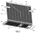
- the condenser 130 comprises a serpentine coil 135, for example made of steel, with several interconnection fins or wires 140, also made for example of steel and spot-welded to the coil.
- the coil 135 and the interconnection wires 140 are arranged to form a grid.
- the condenser 130 comprises a generically rectangular, substantially flat portion 145, of prevailing size, and a bent portion 150 at one end of the condenser 130.
- the bent portion 150 which extends for the whole width of the condenser 130, is bent at an angle of approximately 90° with respect to the flat portion 145.
- the flat portion 145 and the bent portion 150 define two essentially flat portions of a same L-shaped flat body (the condenser 130 ), at a right-angle to each other.
- the flat portion 145 lies vertically and delimits the appliance on the rear
- the flat portion 150 lies horizontally and delimits the appliance on the bottom.
- the bent portion 150 of the condenser 130 has a length sufficient to provide a support surface for the compressor 125.
- the compressor 125 is fixed to the bent portion 150 of the condenser 130 by means of brackets 155.
- the coil 135 has extended terminal ends 135a, 135b for the connection to the hydraulic circuit, particularly to a delivery port of the compressor 125.
- Capillary tubes are used to connect the compressor 125 to the hydraulic circuit, and to connect the condenser 135 to the evaporator.
- the condenser 130 is mounted to the cabinet 100 at the rear thereof, with the flat portion 145 extending vertically along the back plate 120, and the bent portion 150 extending horizontally below the bottom plate 115.
- the condenser 130 is positioned with respect to the cabinet 100 such that the compressor 125 is accommodated within a respective recess ( i.e . a respective opening) formed with respect to the back and bottom plates 120 and 115 of the cabinet.
- brackets 160 are used to attach the flat portion 145 of the condenser (that, in use, extends vertically) to the lateral panels 105 of the cabinet 100, while (two, in the example) brackets 160b are used to connect the bent portion 150 (horizontal, in use) to lateral panels 105.
- the remaining part of the bent portion 150 not occupied by the compressor 125 is used as a support for a tray 165, adapted to receive water which, in use, is originated by the defrost of storage compartment and/or the evaporator.
- a cooling agent fills the closed circuit of the cooling system.
- the cooling agent circulates through the closed circuit from the compressor through the condenser and the evaporator and back to the compressor.
- the cooling agent is first compressed by the compressor, which raises the cooling agent pressure (and temperature).
- the cooling agent flows to the condenser, where its temperature is decreased, causing it to change phase and pass from the gaseous to the liquid one; in this phase change, the cooling agent releases heat, that is dissipated by the condenser and released to the environment.
- the evaporator which is located inside the refrigerator compartment (for example formed in the lining of the refrigerator compartment), the cooling agent evaporates, subtracting heat from the atmosphere within the refrigerator compartment and thus cooling the interior thereof.
- the conventional metal plate used as a lower support for mounting the compressor to the refrigerator cabinet is no longer necessary, because the condenser itself is used as a compressor support. This simplifies the assemblage of the refrigerator, and reduces the number of distinct parts, thereby leading to a reduction of production costs.
- this subsystem of the cooling system may be provided as a preassembled module). This may be expedient from the refrigerator assemblage point of view.
- the area of the recess formed in the back plate 120 of the cabinet 100 where the compressor 125 is accommodated is essentially completely covered by the condenser 130; in particular, the flat portion 145 of the condenser 130 covers the rear of the recess and the bent portion 150 of the condenser 130 covers the bottom of the recess.
- the compressor area (particularly, the compressor 125, its control unit, the filter, the capillary tubes) is protected against unintentional impacts that could damage the cooling system.
- the possibility of accommodating a tray for the defrost water on the condenser facilitates the evaporation of the defrost water, thanks to the heat dissipated by the condenser.
- the condenser may be initially realized in the form of an essentially flat grid, spot-welding the interconnection fins to the serpentine coil, and then a portion thereof may be bent to form the bent portion.
- the present invention is applicable to any type of refrigerator/freezer; for example, in those appliances having distinct cooling systems for different refrigerator compartments (e . g ., a distinct cooling system for the freezer compartment), the two compressors may be both supported by the bent portion of one of the two condensers (the one which is mounted at the bottom of the cabinet).
- bent portion 150 of the condenser 130 has substantially the same width as the flat portion 145
- the bent portion 150 may have a different width, for example smaller than the width of the planar portion 130, provided that the overall size of the bent portion 150 provides a sufficient space for accommodating the compressor(s).
- the condenser 130 instead of being realized in the form of an essentially flat grid a portion of which is subsequently bent to form the bent portion 150, i . e ., instead of being made of a single piece, may be realized as two substantially flat, initially distinct parts, like two separate traditional condensers, of suitable dimensions, which are then connected mechanically and hydraulically to each other so as to form substantially a right angle.
- the resulting condenser thus has a first flat portion and a second flat portion lying in planes forming an angle.
- the second flat portion of the condenser which is arranged horizontally, may be of relatively large size, for example as large as the bottom of the refrigerator, sufficient not only to accommodate the compressor(s), but also to dissipate heat; in this case, provided the first flat portion of the condenser, i . e . the one which in the previously described embodiment is arranged vertically, may even be missing.
Priority Applications (9)
| Application Number | Priority Date | Filing Date | Title |
|---|---|---|---|
| EP08158685.1A EP2136168B1 (de) | 2008-06-20 | 2008-06-20 | Kondensator eines Kühlgeräts und Kühlgerät damit |
| AU2009259606A AU2009259606B2 (en) | 2008-06-20 | 2009-06-16 | A cooling apparatus condenser, and a cooling apparatus including the same |
| CN2009801298250A CN102112828B (zh) | 2008-06-20 | 2009-06-16 | 冷却装置的冷凝器,以及具有该冷凝器的冷却装置 |
| US12/999,355 US8931297B2 (en) | 2008-06-20 | 2009-06-16 | Cooling apparatus condenser, and a cooling apparatus including the same |
| RU2011101992/13A RU2516261C2 (ru) | 2008-06-20 | 2009-06-16 | Конденсатор холодильного устройства и холодильное устройство с таким конденсатором |
| KR1020117001420A KR20110090881A (ko) | 2008-06-20 | 2009-06-16 | 냉각 장치를 위한 응결기 및 이러한 응결기를 포함하는 냉각 장치 |
| MX2010014129A MX2010014129A (es) | 2008-06-20 | 2009-06-16 | Condensador de aparato enfriador y un aparato enfriador que incluye el mismo. |
| PCT/EP2009/004330 WO2009153024A1 (en) | 2008-06-20 | 2009-06-16 | A cooling apparatus condenser, and a cooling apparatus including the same |
| BRPI0915379A BRPI0915379B1 (pt) | 2008-06-20 | 2009-06-16 | aparelho refrigerador, condensador, e, sistema de resfriamento para um aparelho refrigerador. |
Applications Claiming Priority (1)
| Application Number | Priority Date | Filing Date | Title |
|---|---|---|---|
| EP08158685.1A EP2136168B1 (de) | 2008-06-20 | 2008-06-20 | Kondensator eines Kühlgeräts und Kühlgerät damit |
Publications (2)
| Publication Number | Publication Date |
|---|---|
| EP2136168A1 true EP2136168A1 (de) | 2009-12-23 |
| EP2136168B1 EP2136168B1 (de) | 2020-01-15 |
Family
ID=39930376
Family Applications (1)
| Application Number | Title | Priority Date | Filing Date |
|---|---|---|---|
| EP08158685.1A Active EP2136168B1 (de) | 2008-06-20 | 2008-06-20 | Kondensator eines Kühlgeräts und Kühlgerät damit |
Country Status (9)
| Country | Link |
|---|---|
| US (1) | US8931297B2 (de) |
| EP (1) | EP2136168B1 (de) |
| KR (1) | KR20110090881A (de) |
| CN (1) | CN102112828B (de) |
| AU (1) | AU2009259606B2 (de) |
| BR (1) | BRPI0915379B1 (de) |
| MX (1) | MX2010014129A (de) |
| RU (1) | RU2516261C2 (de) |
| WO (1) | WO2009153024A1 (de) |
Cited By (4)
| Publication number | Priority date | Publication date | Assignee | Title |
|---|---|---|---|---|
| WO2012113630A3 (de) * | 2011-02-23 | 2013-08-15 | BSH Bosch und Siemens Hausgeräte GmbH | Elektrisches haushaltsgerät |
| EP2216614A3 (de) * | 2009-02-05 | 2014-01-15 | Liebherr-Hausgeräte Ochsenhausen GmbH | Kühl- und/oder Gefriergerät |
| WO2014102373A1 (en) * | 2012-12-31 | 2014-07-03 | Arcelik Anonim Sirketi | A defrost water evaporation tray, a condenser retainer and a cooling device wherein the same are used |
| WO2017202687A1 (en) * | 2016-05-25 | 2017-11-30 | Arcelik Anonim Sirketi | A cooling device comprising a condenser cover |
Families Citing this family (3)
| Publication number | Priority date | Publication date | Assignee | Title |
|---|---|---|---|---|
| DE102011002645A1 (de) * | 2011-01-13 | 2012-07-19 | BSH Bosch und Siemens Hausgeräte GmbH | Kältegerät |
| CN105744805A (zh) * | 2016-04-15 | 2016-07-06 | 周哲明 | 一种多通道组合水冷板 |
| JP6618624B2 (ja) * | 2016-07-25 | 2019-12-11 | 三菱電機株式会社 | 空気調和機の室外機 |
Citations (15)
| Publication number | Priority date | Publication date | Assignee | Title |
|---|---|---|---|---|
| US1362757A (en) * | 1916-07-07 | 1920-12-21 | Stokes Douglas Henry | Refrigerating apparatus |
| GB338447A (en) * | 1929-02-04 | 1930-11-20 | Westinghouse Electric & Mfg Co | Improvements in or relating to refrigerating apparatus |
| GB450299A (en) | 1935-01-26 | 1936-07-14 | British Thomson Houston Co Ltd | Improvements in and relating to refrigerators |
| US2311947A (en) * | 1941-10-30 | 1943-02-23 | Gen Motors Corp | Refrigerating apparatus |
| DE1174339B (de) * | 1959-10-27 | 1964-07-23 | Schiff & Stern Ges M B H | Motoraggregat fuer nach dem Waermepumpen-prinzip arbeitende Kaeltemaschinen fuer Kuehlschraenke |
| FR2099803A5 (en) * | 1970-06-25 | 1972-03-17 | Luft Kaltetechn K | Motor-compressor heat exchange unit - silenced refrigerator or heat pump |
| EP0125642A2 (de) | 1983-05-16 | 1984-11-21 | INDUSTRIE ZANUSSI S.p.A. | Mit einem verbesserten Verflüssiger versehener Kühlschrank |
| US4490990A (en) * | 1983-12-29 | 1985-01-01 | General Electric Company | High-side refrigeration system assembly adapted to be mounted in a refrigerator machinery compartment |
| EP0364985A2 (de) | 1988-10-20 | 1990-04-25 | INDUSTRIE ZANUSSI S.p.A. | Verfahren zur Herstellung einer kombinierten Kühl- und Gefriervorrichtung |
| US5117523A (en) * | 1990-11-26 | 1992-06-02 | General Electric Company | High side refrigeration system mounting arrangement |
| US5502983A (en) | 1993-09-03 | 1996-04-02 | Whirlpool Corporation | Apparatus and method of forming a refrigerator condenser |
| JP2000146384A (ja) * | 1998-11-12 | 2000-05-26 | Hoshizaki Electric Co Ltd | 製氷機 |
| JP2003322456A (ja) * | 2002-04-26 | 2003-11-14 | Hitachi Home & Life Solutions Inc | 冷蔵庫 |
| WO2004081473A1 (en) | 2003-03-10 | 2004-09-23 | Electrolux Home Products Corporation N.V. | Noise reduction system |
| US20070130987A1 (en) * | 2005-12-12 | 2007-06-14 | Kazunori Shimizu | Condensing unit and cooling apparatus equipped with condensing unit |
Family Cites Families (18)
| Publication number | Priority date | Publication date | Assignee | Title |
|---|---|---|---|---|
| US1932172A (en) * | 1929-12-23 | 1933-10-24 | Chieago Pneumatic Tool Company | Mechanical refrigerating apparatus |
| US2081970A (en) * | 1930-07-23 | 1937-06-01 | Universal Oil Prod Co | Apparatus and process for heating fluids |
| US2091584A (en) * | 1934-05-11 | 1937-08-31 | William L Brown | Cooling unit for artificial refrigerating systems |
| US2087257A (en) * | 1934-07-07 | 1937-07-20 | Reconstruction Finance Corp | Refrigerator cabinet |
| US2263068A (en) * | 1938-04-09 | 1941-11-18 | Borg Warner | Apparatus for heat transfer |
| US2659213A (en) * | 1951-03-15 | 1953-11-17 | Philco Corp | Refrigerating apparatus and cabinet structure |
| US3035421A (en) * | 1961-03-06 | 1962-05-22 | Chrysler Corp | Air outlet control for an air conditioner |
| US4270596A (en) * | 1979-03-05 | 1981-06-02 | Bio-Energy Systems, Inc. | Tube mat heat exchanger |
| SU1601473A1 (ru) * | 1987-06-26 | 1990-10-23 | В. В. Ма.,ьцев | Система охлаждени |
| SU1684574A1 (ru) * | 1989-04-18 | 1991-10-15 | Предприятие П/Я В-8695 | Бытовой холодильник |
| US5042565A (en) * | 1990-01-30 | 1991-08-27 | Rockwell International Corporation | Fiber reinforced composite leading edge heat exchanger and method for producing same |
| US5966958A (en) * | 1998-07-17 | 1999-10-19 | Habco Beverage Systems Inc. | Condensate tray in a refrigeration assembly |
| CN1321529A (zh) * | 2001-04-16 | 2001-11-14 | 于佳辉 | 低成本低能耗高回收率减压浓缩回收机组及其设计方案 |
| KR100524654B1 (ko) * | 2003-06-09 | 2005-10-31 | 위니아만도 주식회사 | 김치저장고의 응축기와 냉각팬 설치구조 |
| CN2660434Y (zh) * | 2003-08-27 | 2004-12-01 | 海尔集团公司 | 具有蒸发除霜水功能的电冰箱 |
| US6804976B1 (en) * | 2003-12-12 | 2004-10-19 | John F. Dain | High reliability multi-tube thermal exchange structure |
| JP2005332024A (ja) * | 2004-05-18 | 2005-12-02 | Matsushita Electric Ind Co Ltd | 自動販売機 |
| KR20060016665A (ko) * | 2004-08-18 | 2006-02-22 | 삼성전자주식회사 | 냉장고 |
-
2008
- 2008-06-20 EP EP08158685.1A patent/EP2136168B1/de active Active
-
2009
- 2009-06-16 MX MX2010014129A patent/MX2010014129A/es not_active Application Discontinuation
- 2009-06-16 RU RU2011101992/13A patent/RU2516261C2/ru not_active IP Right Cessation
- 2009-06-16 WO PCT/EP2009/004330 patent/WO2009153024A1/en active Application Filing
- 2009-06-16 AU AU2009259606A patent/AU2009259606B2/en active Active
- 2009-06-16 CN CN2009801298250A patent/CN102112828B/zh active Active
- 2009-06-16 BR BRPI0915379A patent/BRPI0915379B1/pt active IP Right Grant
- 2009-06-16 US US12/999,355 patent/US8931297B2/en active Active
- 2009-06-16 KR KR1020117001420A patent/KR20110090881A/ko not_active Application Discontinuation
Patent Citations (15)
| Publication number | Priority date | Publication date | Assignee | Title |
|---|---|---|---|---|
| US1362757A (en) * | 1916-07-07 | 1920-12-21 | Stokes Douglas Henry | Refrigerating apparatus |
| GB338447A (en) * | 1929-02-04 | 1930-11-20 | Westinghouse Electric & Mfg Co | Improvements in or relating to refrigerating apparatus |
| GB450299A (en) | 1935-01-26 | 1936-07-14 | British Thomson Houston Co Ltd | Improvements in and relating to refrigerators |
| US2311947A (en) * | 1941-10-30 | 1943-02-23 | Gen Motors Corp | Refrigerating apparatus |
| DE1174339B (de) * | 1959-10-27 | 1964-07-23 | Schiff & Stern Ges M B H | Motoraggregat fuer nach dem Waermepumpen-prinzip arbeitende Kaeltemaschinen fuer Kuehlschraenke |
| FR2099803A5 (en) * | 1970-06-25 | 1972-03-17 | Luft Kaltetechn K | Motor-compressor heat exchange unit - silenced refrigerator or heat pump |
| EP0125642A2 (de) | 1983-05-16 | 1984-11-21 | INDUSTRIE ZANUSSI S.p.A. | Mit einem verbesserten Verflüssiger versehener Kühlschrank |
| US4490990A (en) * | 1983-12-29 | 1985-01-01 | General Electric Company | High-side refrigeration system assembly adapted to be mounted in a refrigerator machinery compartment |
| EP0364985A2 (de) | 1988-10-20 | 1990-04-25 | INDUSTRIE ZANUSSI S.p.A. | Verfahren zur Herstellung einer kombinierten Kühl- und Gefriervorrichtung |
| US5117523A (en) * | 1990-11-26 | 1992-06-02 | General Electric Company | High side refrigeration system mounting arrangement |
| US5502983A (en) | 1993-09-03 | 1996-04-02 | Whirlpool Corporation | Apparatus and method of forming a refrigerator condenser |
| JP2000146384A (ja) * | 1998-11-12 | 2000-05-26 | Hoshizaki Electric Co Ltd | 製氷機 |
| JP2003322456A (ja) * | 2002-04-26 | 2003-11-14 | Hitachi Home & Life Solutions Inc | 冷蔵庫 |
| WO2004081473A1 (en) | 2003-03-10 | 2004-09-23 | Electrolux Home Products Corporation N.V. | Noise reduction system |
| US20070130987A1 (en) * | 2005-12-12 | 2007-06-14 | Kazunori Shimizu | Condensing unit and cooling apparatus equipped with condensing unit |
Cited By (7)
| Publication number | Priority date | Publication date | Assignee | Title |
|---|---|---|---|---|
| EP2216614A3 (de) * | 2009-02-05 | 2014-01-15 | Liebherr-Hausgeräte Ochsenhausen GmbH | Kühl- und/oder Gefriergerät |
| WO2012113630A3 (de) * | 2011-02-23 | 2013-08-15 | BSH Bosch und Siemens Hausgeräte GmbH | Elektrisches haushaltsgerät |
| CN103392105A (zh) * | 2011-02-23 | 2013-11-13 | Bsh博世和西门子家用电器有限公司 | 电的家用器具 |
| RU2558939C2 (ru) * | 2011-02-23 | 2015-08-10 | Бсх Хаусгерете Гмбх | Электрический бытовой прибор |
| CN103392105B (zh) * | 2011-02-23 | 2016-08-10 | Bsh家用电器有限公司 | 电的家用器具 |
| WO2014102373A1 (en) * | 2012-12-31 | 2014-07-03 | Arcelik Anonim Sirketi | A defrost water evaporation tray, a condenser retainer and a cooling device wherein the same are used |
| WO2017202687A1 (en) * | 2016-05-25 | 2017-11-30 | Arcelik Anonim Sirketi | A cooling device comprising a condenser cover |
Also Published As
| Publication number | Publication date |
|---|---|
| US8931297B2 (en) | 2015-01-13 |
| RU2516261C2 (ru) | 2014-05-20 |
| KR20110090881A (ko) | 2011-08-10 |
| CN102112828A (zh) | 2011-06-29 |
| MX2010014129A (es) | 2011-03-21 |
| AU2009259606B2 (en) | 2015-07-09 |
| CN102112828B (zh) | 2013-05-15 |
| BRPI0915379B1 (pt) | 2020-01-28 |
| EP2136168B1 (de) | 2020-01-15 |
| US20110154846A1 (en) | 2011-06-30 |
| BRPI0915379A2 (pt) | 2015-11-03 |
| RU2011101992A (ru) | 2012-07-27 |
| AU2009259606A1 (en) | 2009-12-23 |
| WO2009153024A1 (en) | 2009-12-23 |
Similar Documents
| Publication | Publication Date | Title |
|---|---|---|
| US8931297B2 (en) | Cooling apparatus condenser, and a cooling apparatus including the same | |
| US7350374B1 (en) | Consumer refrigerator | |
| US2773362A (en) | Refrigerators for freezing food and storage of frozen food | |
| JP5957684B2 (ja) | 冷蔵庫 | |
| JP6645029B2 (ja) | 自動販売機 | |
| EP2743618B1 (de) | Kühlschrank für Lebensmittel | |
| CN102007348A (zh) | 具有弯曲蒸发器表面的冰箱 | |
| WO2019020175A1 (en) | COOLING APPARATUS COMPRISING A CONDENSER | |
| JP2007064601A (ja) | 冷蔵庫 | |
| JP2005156105A (ja) | 冷蔵庫 | |
| EP3063481B1 (de) | Kältevorrichtung mit verbessertem tauwassersammelbehälter | |
| JP5514037B2 (ja) | 冷蔵庫 | |
| CN210772906U (zh) | 一体式制冷机组及冷藏车 | |
| CN219913612U (zh) | 冰箱 | |
| CN219841692U (zh) | 制冷设备 | |
| JP2006010239A (ja) | 冷蔵庫 | |
| CN215724248U (zh) | 一种制冷机组、集装箱以及冷链运输车辆 | |
| CN217058087U (zh) | 冰箱 | |
| CN210625070U (zh) | 蒸发器固定结构优化的冰箱 | |
| AU2021413536B2 (en) | Refrigerator | |
| GB2154722A (en) | Refrigerator | |
| JP6976565B2 (ja) | 冷蔵庫 | |
| JP4244862B2 (ja) | 冷蔵庫 | |
| US10488102B2 (en) | Household cooling appliance with an ice tray and a cooling device in a door | |
| EP2132503A2 (de) | Mit einem verdampfer integrierter kanal und kühlvorrichtung damit |
Legal Events
| Date | Code | Title | Description |
|---|---|---|---|
| PUAI | Public reference made under article 153(3) epc to a published international application that has entered the european phase |
Free format text: ORIGINAL CODE: 0009012 |
|
| AK | Designated contracting states |
Kind code of ref document: A1 Designated state(s): AT BE BG CH CY CZ DE DK EE ES FI FR GB GR HR HU IE IS IT LI LT LU LV MC MT NL NO PL PT RO SE SI SK TR |
|
| AX | Request for extension of the european patent |
Extension state: AL BA MK RS |
|
| 17P | Request for examination filed |
Effective date: 20100611 |
|
| 17Q | First examination report despatched |
Effective date: 20100708 |
|
| AKX | Designation fees paid |
Designated state(s): AT BE BG CH CY CZ DE DK EE ES FI FR GB GR HR HU IE IS IT LI LT LU LV MC MT NL NO PL PT RO SE SI SK TR |
|
| RAP1 | Party data changed (applicant data changed or rights of an application transferred) |
Owner name: ELECTROLUX HOME PRODUCTS CORPORATION N.V. |
|
| RAP1 | Party data changed (applicant data changed or rights of an application transferred) |
Owner name: ELECTROLUX HOME PRODUCTS CORPORATION N.V. |
|
| STAA | Information on the status of an ep patent application or granted ep patent |
Free format text: STATUS: EXAMINATION IS IN PROGRESS |
|
| RIC1 | Information provided on ipc code assigned before grant |
Ipc: F28F 1/12 20060101ALN20190621BHEP Ipc: F25D 23/00 20060101AFI20190621BHEP Ipc: F28F 9/00 20060101ALN20190621BHEP Ipc: F25B 39/04 20060101ALN20190621BHEP Ipc: F28D 1/047 20060101ALN20190621BHEP Ipc: F25D 21/14 20060101ALN20190621BHEP |
|
| GRAP | Despatch of communication of intention to grant a patent |
Free format text: ORIGINAL CODE: EPIDOSNIGR1 |
|
| STAA | Information on the status of an ep patent application or granted ep patent |
Free format text: STATUS: GRANT OF PATENT IS INTENDED |
|
| INTG | Intention to grant announced |
Effective date: 20190802 |
|
| GRAS | Grant fee paid |
Free format text: ORIGINAL CODE: EPIDOSNIGR3 |
|
| GRAA | (expected) grant |
Free format text: ORIGINAL CODE: 0009210 |
|
| STAA | Information on the status of an ep patent application or granted ep patent |
Free format text: STATUS: THE PATENT HAS BEEN GRANTED |
|
| AK | Designated contracting states |
Kind code of ref document: B1 Designated state(s): AT BE BG CH CY CZ DE DK EE ES FI FR GB GR HR HU IE IS IT LI LT LU LV MC MT NL NO PL PT RO SE SI SK TR |
|
| REG | Reference to a national code |
Ref country code: GB Ref legal event code: FG4D Ref country code: CH Ref legal event code: EP |
|
| REG | Reference to a national code |
Ref country code: IE Ref legal event code: FG4D |
|
| REG | Reference to a national code |
Ref country code: AT Ref legal event code: REF Ref document number: 1225506 Country of ref document: AT Kind code of ref document: T Effective date: 20200215 |
|
| REG | Reference to a national code |
Ref country code: DE Ref legal event code: R096 Ref document number: 602008062003 Country of ref document: DE |
|
| REG | Reference to a national code |
Ref country code: NL Ref legal event code: MP Effective date: 20200115 |
|
| REG | Reference to a national code |
Ref country code: LT Ref legal event code: MG4D |
|
| PG25 | Lapsed in a contracting state [announced via postgrant information from national office to epo] |
Ref country code: FI Free format text: LAPSE BECAUSE OF FAILURE TO SUBMIT A TRANSLATION OF THE DESCRIPTION OR TO PAY THE FEE WITHIN THE PRESCRIBED TIME-LIMIT Effective date: 20200115 Ref country code: NO Free format text: LAPSE BECAUSE OF FAILURE TO SUBMIT A TRANSLATION OF THE DESCRIPTION OR TO PAY THE FEE WITHIN THE PRESCRIBED TIME-LIMIT Effective date: 20200415 Ref country code: NL Free format text: LAPSE BECAUSE OF FAILURE TO SUBMIT A TRANSLATION OF THE DESCRIPTION OR TO PAY THE FEE WITHIN THE PRESCRIBED TIME-LIMIT Effective date: 20200115 Ref country code: PT Free format text: LAPSE BECAUSE OF FAILURE TO SUBMIT A TRANSLATION OF THE DESCRIPTION OR TO PAY THE FEE WITHIN THE PRESCRIBED TIME-LIMIT Effective date: 20200607 |
|
| PG25 | Lapsed in a contracting state [announced via postgrant information from national office to epo] |
Ref country code: SE Free format text: LAPSE BECAUSE OF FAILURE TO SUBMIT A TRANSLATION OF THE DESCRIPTION OR TO PAY THE FEE WITHIN THE PRESCRIBED TIME-LIMIT Effective date: 20200115 Ref country code: LV Free format text: LAPSE BECAUSE OF FAILURE TO SUBMIT A TRANSLATION OF THE DESCRIPTION OR TO PAY THE FEE WITHIN THE PRESCRIBED TIME-LIMIT Effective date: 20200115 Ref country code: IS Free format text: LAPSE BECAUSE OF FAILURE TO SUBMIT A TRANSLATION OF THE DESCRIPTION OR TO PAY THE FEE WITHIN THE PRESCRIBED TIME-LIMIT Effective date: 20200515 Ref country code: HR Free format text: LAPSE BECAUSE OF FAILURE TO SUBMIT A TRANSLATION OF THE DESCRIPTION OR TO PAY THE FEE WITHIN THE PRESCRIBED TIME-LIMIT Effective date: 20200115 Ref country code: GR Free format text: LAPSE BECAUSE OF FAILURE TO SUBMIT A TRANSLATION OF THE DESCRIPTION OR TO PAY THE FEE WITHIN THE PRESCRIBED TIME-LIMIT Effective date: 20200416 Ref country code: BG Free format text: LAPSE BECAUSE OF FAILURE TO SUBMIT A TRANSLATION OF THE DESCRIPTION OR TO PAY THE FEE WITHIN THE PRESCRIBED TIME-LIMIT Effective date: 20200415 |
|
| REG | Reference to a national code |
Ref country code: DE Ref legal event code: R097 Ref document number: 602008062003 Country of ref document: DE |
|
| PG25 | Lapsed in a contracting state [announced via postgrant information from national office to epo] |
Ref country code: ES Free format text: LAPSE BECAUSE OF FAILURE TO SUBMIT A TRANSLATION OF THE DESCRIPTION OR TO PAY THE FEE WITHIN THE PRESCRIBED TIME-LIMIT Effective date: 20200115 Ref country code: EE Free format text: LAPSE BECAUSE OF FAILURE TO SUBMIT A TRANSLATION OF THE DESCRIPTION OR TO PAY THE FEE WITHIN THE PRESCRIBED TIME-LIMIT Effective date: 20200115 Ref country code: DK Free format text: LAPSE BECAUSE OF FAILURE TO SUBMIT A TRANSLATION OF THE DESCRIPTION OR TO PAY THE FEE WITHIN THE PRESCRIBED TIME-LIMIT Effective date: 20200115 Ref country code: CZ Free format text: LAPSE BECAUSE OF FAILURE TO SUBMIT A TRANSLATION OF THE DESCRIPTION OR TO PAY THE FEE WITHIN THE PRESCRIBED TIME-LIMIT Effective date: 20200115 Ref country code: RO Free format text: LAPSE BECAUSE OF FAILURE TO SUBMIT A TRANSLATION OF THE DESCRIPTION OR TO PAY THE FEE WITHIN THE PRESCRIBED TIME-LIMIT Effective date: 20200115 Ref country code: LT Free format text: LAPSE BECAUSE OF FAILURE TO SUBMIT A TRANSLATION OF THE DESCRIPTION OR TO PAY THE FEE WITHIN THE PRESCRIBED TIME-LIMIT Effective date: 20200115 Ref country code: SK Free format text: LAPSE BECAUSE OF FAILURE TO SUBMIT A TRANSLATION OF THE DESCRIPTION OR TO PAY THE FEE WITHIN THE PRESCRIBED TIME-LIMIT Effective date: 20200115 |
|
| REG | Reference to a national code |
Ref country code: AT Ref legal event code: MK05 Ref document number: 1225506 Country of ref document: AT Kind code of ref document: T Effective date: 20200115 |
|
| PLBE | No opposition filed within time limit |
Free format text: ORIGINAL CODE: 0009261 |
|
| STAA | Information on the status of an ep patent application or granted ep patent |
Free format text: STATUS: NO OPPOSITION FILED WITHIN TIME LIMIT |
|
| 26N | No opposition filed |
Effective date: 20201016 |
|
| PG25 | Lapsed in a contracting state [announced via postgrant information from national office to epo] |
Ref country code: AT Free format text: LAPSE BECAUSE OF FAILURE TO SUBMIT A TRANSLATION OF THE DESCRIPTION OR TO PAY THE FEE WITHIN THE PRESCRIBED TIME-LIMIT Effective date: 20200115 Ref country code: MC Free format text: LAPSE BECAUSE OF FAILURE TO SUBMIT A TRANSLATION OF THE DESCRIPTION OR TO PAY THE FEE WITHIN THE PRESCRIBED TIME-LIMIT Effective date: 20200115 |
|
| REG | Reference to a national code |
Ref country code: CH Ref legal event code: PL |
|
| PG25 | Lapsed in a contracting state [announced via postgrant information from national office to epo] |
Ref country code: PL Free format text: LAPSE BECAUSE OF FAILURE TO SUBMIT A TRANSLATION OF THE DESCRIPTION OR TO PAY THE FEE WITHIN THE PRESCRIBED TIME-LIMIT Effective date: 20200115 Ref country code: SI Free format text: LAPSE BECAUSE OF FAILURE TO SUBMIT A TRANSLATION OF THE DESCRIPTION OR TO PAY THE FEE WITHIN THE PRESCRIBED TIME-LIMIT Effective date: 20200115 |
|
| GBPC | Gb: european patent ceased through non-payment of renewal fee |
Effective date: 20200620 |
|
| PG25 | Lapsed in a contracting state [announced via postgrant information from national office to epo] |
Ref country code: LU Free format text: LAPSE BECAUSE OF NON-PAYMENT OF DUE FEES Effective date: 20200620 |
|
| REG | Reference to a national code |
Ref country code: BE Ref legal event code: MM Effective date: 20200630 |
|
| PG25 | Lapsed in a contracting state [announced via postgrant information from national office to epo] |
Ref country code: GB Free format text: LAPSE BECAUSE OF NON-PAYMENT OF DUE FEES Effective date: 20200620 Ref country code: FR Free format text: LAPSE BECAUSE OF NON-PAYMENT OF DUE FEES Effective date: 20200630 Ref country code: LI Free format text: LAPSE BECAUSE OF NON-PAYMENT OF DUE FEES Effective date: 20200630 Ref country code: IE Free format text: LAPSE BECAUSE OF NON-PAYMENT OF DUE FEES Effective date: 20200620 Ref country code: CH Free format text: LAPSE BECAUSE OF NON-PAYMENT OF DUE FEES Effective date: 20200630 |
|
| PG25 | Lapsed in a contracting state [announced via postgrant information from national office to epo] |
Ref country code: BE Free format text: LAPSE BECAUSE OF NON-PAYMENT OF DUE FEES Effective date: 20200630 |
|
| PG25 | Lapsed in a contracting state [announced via postgrant information from national office to epo] |
Ref country code: TR Free format text: LAPSE BECAUSE OF FAILURE TO SUBMIT A TRANSLATION OF THE DESCRIPTION OR TO PAY THE FEE WITHIN THE PRESCRIBED TIME-LIMIT Effective date: 20200115 Ref country code: MT Free format text: LAPSE BECAUSE OF FAILURE TO SUBMIT A TRANSLATION OF THE DESCRIPTION OR TO PAY THE FEE WITHIN THE PRESCRIBED TIME-LIMIT Effective date: 20200115 Ref country code: CY Free format text: LAPSE BECAUSE OF FAILURE TO SUBMIT A TRANSLATION OF THE DESCRIPTION OR TO PAY THE FEE WITHIN THE PRESCRIBED TIME-LIMIT Effective date: 20200115 |
|
| PGFP | Annual fee paid to national office [announced via postgrant information from national office to epo] |
Ref country code: DE Payment date: 20230627 Year of fee payment: 16 |
|
| P01 | Opt-out of the competence of the unified patent court (upc) registered |
Effective date: 20230625 |
|
| PGFP | Annual fee paid to national office [announced via postgrant information from national office to epo] |
Ref country code: IT Payment date: 20230620 Year of fee payment: 16 |