EP2136126B1 - Operationsleuchte - Google Patents
Operationsleuchte Download PDFInfo
- Publication number
- EP2136126B1 EP2136126B1 EP08011294A EP08011294A EP2136126B1 EP 2136126 B1 EP2136126 B1 EP 2136126B1 EP 08011294 A EP08011294 A EP 08011294A EP 08011294 A EP08011294 A EP 08011294A EP 2136126 B1 EP2136126 B1 EP 2136126B1
- Authority
- EP
- European Patent Office
- Prior art keywords
- light
- surgical lamp
- illuminants
- lamp according
- central axis
- Prior art date
- Legal status (The legal status is an assumption and is not a legal conclusion. Google has not performed a legal analysis and makes no representation as to the accuracy of the status listed.)
- Active
Links
Images


Classifications
-
- A—HUMAN NECESSITIES
- A61—MEDICAL OR VETERINARY SCIENCE; HYGIENE
- A61B—DIAGNOSIS; SURGERY; IDENTIFICATION
- A61B90/00—Instruments, implements or accessories specially adapted for surgery or diagnosis and not covered by any of the groups A61B1/00 - A61B50/00, e.g. for luxation treatment or for protecting wound edges
- A61B90/30—Devices for illuminating a surgical field, the devices having an interrelation with other surgical devices or with a surgical procedure
- A61B90/35—Supports therefor
-
- A—HUMAN NECESSITIES
- A61—MEDICAL OR VETERINARY SCIENCE; HYGIENE
- A61B—DIAGNOSIS; SURGERY; IDENTIFICATION
- A61B90/00—Instruments, implements or accessories specially adapted for surgery or diagnosis and not covered by any of the groups A61B1/00 - A61B50/00, e.g. for luxation treatment or for protecting wound edges
- A61B90/30—Devices for illuminating a surgical field, the devices having an interrelation with other surgical devices or with a surgical procedure
-
- F—MECHANICAL ENGINEERING; LIGHTING; HEATING; WEAPONS; BLASTING
- F21—LIGHTING
- F21V—FUNCTIONAL FEATURES OR DETAILS OF LIGHTING DEVICES OR SYSTEMS THEREOF; STRUCTURAL COMBINATIONS OF LIGHTING DEVICES WITH OTHER ARTICLES, NOT OTHERWISE PROVIDED FOR
- F21V23/00—Arrangement of electric circuit elements in or on lighting devices
- F21V23/04—Arrangement of electric circuit elements in or on lighting devices the elements being switches
-
- H—ELECTRICITY
- H05—ELECTRIC TECHNIQUES NOT OTHERWISE PROVIDED FOR
- H05B—ELECTRIC HEATING; ELECTRIC LIGHT SOURCES NOT OTHERWISE PROVIDED FOR; CIRCUIT ARRANGEMENTS FOR ELECTRIC LIGHT SOURCES, IN GENERAL
- H05B45/00—Circuit arrangements for operating light-emitting diodes [LED]
-
- H—ELECTRICITY
- H05—ELECTRIC TECHNIQUES NOT OTHERWISE PROVIDED FOR
- H05B—ELECTRIC HEATING; ELECTRIC LIGHT SOURCES NOT OTHERWISE PROVIDED FOR; CIRCUIT ARRANGEMENTS FOR ELECTRIC LIGHT SOURCES, IN GENERAL
- H05B45/00—Circuit arrangements for operating light-emitting diodes [LED]
- H05B45/10—Controlling the intensity of the light
-
- F—MECHANICAL ENGINEERING; LIGHTING; HEATING; WEAPONS; BLASTING
- F21—LIGHTING
- F21W—INDEXING SCHEME ASSOCIATED WITH SUBCLASSES F21K, F21L, F21S and F21V, RELATING TO USES OR APPLICATIONS OF LIGHTING DEVICES OR SYSTEMS
- F21W2131/00—Use or application of lighting devices or systems not provided for in codes F21W2102/00-F21W2121/00
- F21W2131/20—Lighting for medical use
- F21W2131/202—Lighting for medical use for dentistry
-
- F—MECHANICAL ENGINEERING; LIGHTING; HEATING; WEAPONS; BLASTING
- F21—LIGHTING
- F21W—INDEXING SCHEME ASSOCIATED WITH SUBCLASSES F21K, F21L, F21S and F21V, RELATING TO USES OR APPLICATIONS OF LIGHTING DEVICES OR SYSTEMS
- F21W2131/00—Use or application of lighting devices or systems not provided for in codes F21W2102/00-F21W2121/00
- F21W2131/20—Lighting for medical use
- F21W2131/205—Lighting for medical use for operating theatres
-
- F—MECHANICAL ENGINEERING; LIGHTING; HEATING; WEAPONS; BLASTING
- F21—LIGHTING
- F21Y—INDEXING SCHEME ASSOCIATED WITH SUBCLASSES F21K, F21L, F21S and F21V, RELATING TO THE FORM OR THE KIND OF THE LIGHT SOURCES OR OF THE COLOUR OF THE LIGHT EMITTED
- F21Y2115/00—Light-generating elements of semiconductor light sources
- F21Y2115/10—Light-emitting diodes [LED]
-
- H—ELECTRICITY
- H05—ELECTRIC TECHNIQUES NOT OTHERWISE PROVIDED FOR
- H05B—ELECTRIC HEATING; ELECTRIC LIGHT SOURCES NOT OTHERWISE PROVIDED FOR; CIRCUIT ARRANGEMENTS FOR ELECTRIC LIGHT SOURCES, IN GENERAL
- H05B45/00—Circuit arrangements for operating light-emitting diodes [LED]
- H05B45/10—Controlling the intensity of the light
- H05B45/12—Controlling the intensity of the light using optical feedback
Definitions
- the invention relates to a surgical light with a variable in size and in shape light field and an adjustable light intensity distribution in the light field.
- the lighting requirements of surgical lights are defined in this standard.
- the distribution of the brightness in the light field is also defined.
- the reduction in brightness with increasing distance from the center of the light field is defined so that the diameter at which 50% of the maximum brightness is present, must be at least half such as the diameter at which 10% of the maximum brightness is present.
- the light source is a halogen lamp or gas discharge lamp, which is arranged at the focal point of a large reflector with a diameter of about 500 mm to 1000 mm.
- the diameter of the light field ie the illuminated diameter in the surgical field is increased or decreased and the focus point changed, ie the distance of the brightest illuminated spot in which the reflected light beams intersect, changed by the lamp body of the operating light on a central axis of the lamp body.
- the shape of the light field is circular and structurally not changeable here.
- the operating light usually comprises a central headlight or a central light module, which is rigidly fixed to the lamp body and a plurality of headlights or light modules in an annular arrangement around the central headlight or the central light module.
- the change in the direction of the light emission from the outer headlights or light modules is realized via radially pivotable bulbs or reflectors, or the entire headlight or light modules are radially pivotally adjustable.
- the shape of the luminous field is variable in such a way that, in an ideal focusing, the luminous field is circular and at a defocusing, that is, when the central axes of the outer headlights intersect at a point that is not in the operation plane, with an enlargement the distance of the focal point from the operation plane is more and more in a shape corresponding to the arrangement of the outer headlights.
- the distribution of the light intensity develops with increasing distance between the focal point and the operation plane away from a concentric light distribution, towards a light distribution, in which the radiation beams of the outer headlights are reflected in the illuminated field.
- Another type of surgical lights is performed without the adjustment of the luminous field diameter and the distance of the focal point.
- the lighting data, light field diameter and focal point for an operating point are optimal set.
- the shape of the light field is circular.
- the light field no longer acts homogeneous, but, as in the above-described dissolved light system, with greater distance of the focal point of the surgical site, individual points of light in depict the surgical site.
- the distribution of the light intensity in the light field can be changed by switching on and off of individual light sources, which emit their light centrally to the center of the light field.
- EP-A-1 568 934 a surgical light with separately switchable bulbs for enhanced illumination of the center of the light field shows the disclosure EP 1 568 934 a surgical light with switchable bulbs in the center of the light field to avoid shadows, and the EP-A-1 722 157 a surgical light with concentric areas with light sources that can be switched on and dimmed independently to avoid shadows and optimally illuminate different types of surgical wounds (narrow, deep wounds or large wounds).
- All publications show, however, at the operating point, ie at an optimal distance between the lamp body and the operation level, circular luminous fields.
- EP-A-1 433 998 discloses an operating light with individual light modules whose axes of the light beam are parallel and the light fields of the light beam partially overlap, thus resulting in a luminous field shape, which results essentially from the shape of the lamp body. Individual light modules are used to avoid Shadowing automatically turned off or dimmed. The shape of the light field is invariable.
- the patent application EP-A-1 938 768 shows a surgical lamp with a group of main bulbs, each having a collimated light beam, which intersect at a point in the center of the light field, which is one meter away from the lamp body, and another group of additional bulbs, which are located between the main Are arranged and whose light beams have axes which form a concentric annular light beam with a diameter of 100 to 200 mm around the light beam of the main lighting means.
- the bulbs of both groups are each connected to a controller.
- the patent US 5,068,767 discloses an operating light with an automatic focus point adjustment device.
- a sensor that measures the amount of light reflected from the area of operation outputs the values to a controller that determines the angle of inclination of light sources that are adjusted by motors.
- the optical axes of the light sources are always focused on one point.
- the operating light offers the possibility of changing the light field shape and the light intensity distribution in the light field. This is done without mechanical adjustment.
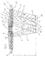
- Fig. 1 shows a perspective view of an embodiment of the surgical lamp according to the invention 1.
- the surgical light 1 comprises a support system 2, a suspension device 3 and a lamp body 4.
- the support system 2 is attached to a ceiling, a wall or a mobile stand.
- the lamp body 4 can be positioned within the radius of action in any spatial position and orientation.
- a light exit opening is arranged on almost the entire surface, which is directed in operation to a surgical field which is located at a certain distance.
- each a handle 5, 6 attached to the two halves of the lamp body 4.
- the two halves of the lamp body are rotatably connected to each other, so that when pivoting the one half, the other half moves to keep the light exit surfaces always in a plane.
- control device 7 is arranged within the lamp body 4, a control device 7 is arranged.
- the control device 7 does not necessarily have to be arranged in the lamp body 4, but can also be accommodated in a separate housing which is arranged on the lamp body 4 or on the suspension device 3.
- the control device 7 is located in an external operating unit, not shown, which is located in a medical supply unit or in / on a wall.
- an operating device 8 is arranged on the outside of the lamp body 4, on the suspension device 3 or in a medical supply unit or in / on a wall.
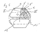
- Fig. 2 is a sectional view of the lamp body 4 with light sources with light beams whose axes intersect with the central axis and with light sources whose light beams whose axes do not intersect with the central axis.
- a plurality of lighting means 9, 9 ', 9'' is provided in the lamp body 4.
- the lamp body 4 has a central axis 12 which is perpendicular to a plane in which the lighting means 9 are arranged.
- the lighting means 9, 9 ', 9'' are arranged annularly or in accordance with the shape of the lamp body 4.
- Each lamp 9, 9 ', 9'' is equipped with a device for bundling the light, here a refractor 10.
- the separate refractors 10 instead of the separate refractors 10 also separate reflectors or bulbs can be used with integrated means for bundling the light.
- the bundled light of the luminous means 9, on the one hand emerges from the refractor 10 in each case in a light beam I, I ', which each has an axis a, a'.
- the light beam I, I ' illuminates an entire light field 11, respectively.
- the lighting means 9 are mounted on inclined mounting surfaces 19 having a vertical axis which is parallel to the axis a, a '.
- the bulbs 9 with the refractors 10 are arranged inclined, so that the axes a, a 'of the light beam I, I' intersect the central axis 12 at an intersection point 13.
- intersection point in the description should be understood to mean that this is not a geometrically exact point but an area in which the axes intersect, with the photometric properties being within a normal tolerance range of an optimal intersection point.
- the area corresponds to a sectional area with a plane perpendicular to the central axis at a distance 1.
- the light beam I, I 'form in a plane which is at a distance 1, perpendicular to the central axis 12, depending on a light field.
- the point of intersection 13 is the point of intersection of the two axes a, a 'with the central axis 12, so that the two luminous fields coincide and together form the luminous field 11 and is defined as a focal point.
- the light field 11 has a certain diameter D and a defined distribution of the light intensity over the diameter of the light field, the normative is predetermined.
- the superposed light beams I, I 'form an approximately circular illuminated field.
- Fig. 2 two light sources 9 are shown, which form the central light field 11.
- the light field 11 is formed by a group of light beam bundles I, I ', which are emitted by the light sources 9, which are distributed uniformly over the light exit surface.
- the bulbs 9 with the refractors 10 are arranged inclined so that the axes a, a 'of the light beam I, I' intersect at the intersection 13, the central axis.
- the lighting means 9 are evenly distributed in the plane to an obstacle, which is introduced between the lamp body 4 and the surgical field and thereby interrupts a light beam, which has a shadowing result, to undercut and thus prevent or mitigate the shadowing.
- the bundled light of the lighting means 9 'and 9 ", respectively, also emerges from the refractor 10 in a light beam bundle II or III, each having an axis b and c, respectively, in order to form a light field which is not arranged centrally.
- the bulbs 9 ', 9''with the refractors 10 are arranged inclined so that the axes b, c of the light beam II, III do not intersect the central axis 12.
- the axes b, c are projected into the plane of the drawing, and the extrapolated axes are therefore shown intersecting the central axis in this plane.
- the axes b, c do not intersect the central axis (see Fig. 4 ).
- the lighting means 9 ', 9' ' are mounted on inclined mounting surfaces 19, each having a vertical axis, which are parallel to the axis b, c.
- the light beam II, III form in a plane which is at a distance 1, perpendicular to the central axis 12, respectively, a light field 14, 15.
- the bulbs 9 ', 9' 'with the refractors 10 are arranged so that the light fields 14th , 15 partially overlap to obtain a uniform brightness distribution.
- Fig. 2 is only ever a light source 9 ', 9''shown, each forming a light field 14, 15.
- the light field 14, 15 is formed by a bevy of light beams II, III, which are emitted by other light sources not shown 9 ', 9'', and which are also distributed evenly in the plane to an obstacle between the lamp body 4 and the surgical field is introduced and thereby interrupts a light beam, which has the consequence of shading, to undercut and thus prevent or mitigate the shadowing.
- the light beams II for the light field 14 intersect at an intersection 17 and the light beams III for the light field 15 intersect at an intersection point 18.
- the lighting means 9 are formed in this embodiment by LEDs, but can also be designed as halogen lamps or gas discharge lamps, optionally with color filters.
- the control device 7 has means for dimming and switching on and off the lighting means 9 9 ', 9' ', as e.g. Current controller, means for transmitting switching and setting information of the switching and setting elements of the operating device 8, a memory area for storing operating parameters and a CPU, from the switching and setting information, based on the stored operating parameters, the required settings for the means for Dimming and switching on and off of the bulbs 9, 9 ', 9' 'calculated or determined on.
- the control device 7 has means for dimming and switching on and off the lighting means 9 9 ', 9' ', as e.g. Current controller, means for transmitting switching and setting information of the switching and setting elements of the operating device 8, a memory area for storing operating parameters and a CPU, from the switching and setting information, based on the stored operating parameters, the required settings for the means for Dimming and switching on and off of the bulbs 9, 9 ', 9' 'calculated or determined on.
- the control device 7 is connected to the lighting means 9, 9 ', 9 ", which are controlled in groups
- a group is formed from a plurality of light sources 9, 9', 9", respectively, which are driven with the same performance parameters.
- the individual groups consist in each case only of light sources 9 whose light beams I, I 'have the same intersection point 13, from light sources 9' whose light beams II have the same intersection point 17, or from light sources 9 '' whose light beams III have the same intersection point 18 to have. But there are several groups of each of the light sources 9, and the light sources 9 'and the light sources 9 "possible.
- the on / off switching element switches the operation light 1 from a standby mode in which the bulbs 9 are not lit to an operation mode.
- the lighting means 9 are operated according to the setting of the adjusting elements. For complete shutdown by switching off the power supply not shown external main switch is provided.
- the element for setting the shape of the luminous field gives to the control device 7 the setting information about the set luminous field shape of the operation light 1. If a round luminous field is set, the means for dimming and switching on and off are then controlled by the control device 7 so that only the Illuminants are operated, which have an intersection with the central axis 12.
- the light intensity distribution adjustment element in the light field gives to the control device 7 the setting information about the set light intensity distribution of the operation light 1. If a standard light intensity distribution is set, the means for dimming and turning on and off are controlled by the control device 7 so that only the light source distribution means Illuminant 9 are operated, the intersection point of which are located on the central axis 12.
- bulbs can be used which are equipped with Lichtbündelvorvorungsungsvoriquessvorraumen that produce no standard light intensity distribution.
- the light intensity distribution can be adjusted so that the outer edge of the light field is more illuminated and the center is lower.
- the light beams I, I ' can then be set a desired light intensity distribution, depending on the intensity of the two different types of light beams. (please refer Fig. 6 )
- the performance parameters are determined and stored empirically.
- the element for setting the distance gives to the control device 7 the information as to which distance of the illuminated field 11 of the lamp body 4, the operating light to be set.
- the lighting means 9 In operation at a set distance 1 of the lamp body from the intersection 13, to which the light sources are directed with the light beams I, I 'in the present embodiment by the control device 7, the lighting means 9 are driven, the axis a, a' of the light rays I, I 'are directed to the intersection 13 and thus the approximately circular illuminated field 11 is formed.
- the lighting means 9 When setting a different distance alternative bulbs, whose distance between the lamp body and the intersection of the axes of their light beams corresponds to the set distance, controlled.
- the illuminated field fulfills the normative specifications regarding the distribution of light intensity in the illuminated field.
- the brightness adjustment element gives to the control device 7 the setting information about the set total brightness of the operation light 1.
- the means for dimming and turning on and off are then controlled by the control device 7 so that the distribution of brightness of the individual light sources 9 remains unchanged and only the overall brightness is changed.
- the operating parameters for the brightness settings are determined empirically and stored in the memory area of the control device 7.
- the operating light 1 comprises a distance sensor for measuring the distance between By detecting the distance of the lamp body 4 from the operation site and relaying the distance information to the control device 7, the control device 7 is capable of detecting the point with the maximum resultant Adjust brightness in the distance of the lamp body 7 from the surgical site, so that the surgical site is illuminated with the greatest brightness.
- the operating light 1 comprises a brightness sensor, which measures the brightness in the surgical site, and means for passing the brightness information to the control device 7.
- the control device 7 By detecting the brightness, wherein one possibility is to detect the brightness in the center of the light field, and another way to detect the average brightness in the entire light field, and passing the brightness information to the control device 7, the control device 7 is able to set the point with the maximum resulting brightness in the distance of the lamp body 4 so that the operation site at a change in the distance of the lamp body 4 is illuminated from the surgical site with the same brightness in the respective detection space.
- Fig. 3 shows a schematic plan view of a lamp body 4 with an arrangement of lighting means 9, of which intersect the axes A, A 'of the light beams I, I' of the operating lights 9 with the central axis.
- the entire light exit surface ie the lower side of both halves of the lamp body 4, is provided with lighting means 9 with the exception of a narrow edge region (here are only five Illuminant 9 shown). In this case, only those are in operation whose axis a, a 'intersects with the central axis 12 by these light beams I, I', a circular illuminated field 11 is formed.
- Fig. 4 shows a schematic plan view of a lamp body 4 with an arrangement of lighting means 9, of which the axes b, c of the light beams II, III of the operating lights 9 do not intersect with the central axis 12. In this case, mainly those are in operation whose axis b, c does not intersect with the central axis 12.
- illuminants 9 can also be in operation in which the axes a, a 'of the light rays I, I' intersect with the central axis 12 (see FIG Fig. 3 ). The remaining area is illuminated by further light sources 9 whose light beams do not intersect with the central axis 12.
- Fig. 5 shows a distribution of light intensity in a plane which is located at a distance of one meter perpendicular to the central axis 12. Above the diameter of the luminous field, the light intensity is here applied to luminous means 9 with light bundling means 10, which produce a standard-compliant luminous field.
- the solid line represents the distribution of the luminous intensity over a diameter D of the luminous field. This course is achieved when the axes of all the light beams intersect at the point of intersection 13.
- the above normative requirements are met.
- the overall brightness is set by the proportionate power setting of the respective lamps.
- Fig. 6 shows a distribution of the light intensity over the diameter of the light field with a light beam means, which is a standard-compliant light field, and light beam means which produce no standard-compliant light field.
- the dashed line shows the luminous intensity distribution in a luminous field that is not standard.
- the overall brightness is also set here by the proportionate power setting of the respective bulbs.
- the settings for the operating parameters for a standardized light field distribution and a light field distribution with the same brightness over the entire light field are stored in the memory area of the control device (7). However, it is also possible to store any light field distribution by the user.
Landscapes
- Health & Medical Sciences (AREA)
- Engineering & Computer Science (AREA)
- Surgery (AREA)
- Life Sciences & Earth Sciences (AREA)
- General Engineering & Computer Science (AREA)
- Public Health (AREA)
- Nuclear Medicine, Radiotherapy & Molecular Imaging (AREA)
- Biomedical Technology (AREA)
- Heart & Thoracic Surgery (AREA)
- Medical Informatics (AREA)
- Molecular Biology (AREA)
- Animal Behavior & Ethology (AREA)
- General Health & Medical Sciences (AREA)
- Oral & Maxillofacial Surgery (AREA)
- Pathology (AREA)
- Veterinary Medicine (AREA)
- Non-Portable Lighting Devices Or Systems Thereof (AREA)
- Circuit Arrangement For Electric Light Sources In General (AREA)
- Eye Examination Apparatus (AREA)
- Dry Shavers And Clippers (AREA)
- Endoscopes (AREA)
- Lighting Device Outwards From Vehicle And Optical Signal (AREA)
- Materials For Medical Uses (AREA)
Priority Applications (5)
| Application Number | Priority Date | Filing Date | Title |
|---|---|---|---|
| PL08011294T PL2136126T3 (pl) | 2008-06-20 | 2008-06-20 | Lampa operacyjna |
| AT08011294T ATE479051T1 (de) | 2008-06-20 | 2008-06-20 | Operationsleuchte |
| DE502008001209T DE502008001209D1 (de) | 2008-06-20 | 2008-06-20 | Operationsleuchte |
| EP08011294A EP2136126B1 (de) | 2008-06-20 | 2008-06-20 | Operationsleuchte |
| US12/487,167 US9016916B2 (en) | 2008-06-20 | 2009-06-18 | Surgical lamp field shape |
Applications Claiming Priority (1)
| Application Number | Priority Date | Filing Date | Title |
|---|---|---|---|
| EP08011294A EP2136126B1 (de) | 2008-06-20 | 2008-06-20 | Operationsleuchte |
Publications (2)
| Publication Number | Publication Date |
|---|---|
| EP2136126A1 EP2136126A1 (de) | 2009-12-23 |
| EP2136126B1 true EP2136126B1 (de) | 2010-08-25 |
Family
ID=40039671
Family Applications (1)
| Application Number | Title | Priority Date | Filing Date |
|---|---|---|---|
| EP08011294A Active EP2136126B1 (de) | 2008-06-20 | 2008-06-20 | Operationsleuchte |
Country Status (5)
| Country | Link |
|---|---|
| US (1) | US9016916B2 (pl) |
| EP (1) | EP2136126B1 (pl) |
| AT (1) | ATE479051T1 (pl) |
| DE (1) | DE502008001209D1 (pl) |
| PL (1) | PL2136126T3 (pl) |
Cited By (2)
| Publication number | Priority date | Publication date | Assignee | Title |
|---|---|---|---|---|
| RU191645U1 (ru) * | 2018-12-05 | 2019-08-15 | Общество с ограниченной ответственностью "Аксима" | Светодиодный хирургический светильник |
| EP4332433A1 (de) * | 2022-09-05 | 2024-03-06 | Drägerwerk AG & Co. KGaA | Beleuchtungsvorrichtung und beleuchtungsverfahren mit kontrastveränderung |
Families Citing this family (26)
| Publication number | Priority date | Publication date | Assignee | Title |
|---|---|---|---|---|
| DE502008001126D1 (de) * | 2008-06-20 | 2010-09-23 | Trumpf Medizin Systeme Gmbh & Co Kg | Operationsleuchte mit Aufhängevorrichtung |
| CN103109127B (zh) * | 2010-08-17 | 2016-04-20 | 皇家飞利浦电子股份有限公司 | 用于宽带和窄带照射的外科手术灯 |
| ES2612915T3 (es) | 2010-09-28 | 2017-05-19 | Trumpf Medizin Systeme Gmbh + Co. Kg | Lámpara quirúrgica con un dispositivo de mando estéril |
| WO2012154627A2 (en) * | 2011-05-06 | 2012-11-15 | California Institute Of Technology | Light delivery device and related compositions, methods and systems |
| USD699879S1 (en) | 2011-08-19 | 2014-02-18 | Trumpf Medizin Systeme Gmbh + Co. Kg | Medical lamp |
| US9500340B2 (en) * | 2011-10-25 | 2016-11-22 | A-Dec, Inc. | Dental light using LEDs |
| US9730851B2 (en) | 2012-09-07 | 2017-08-15 | Allen Medical Systems, Inc. | Surgical support system |
| US9107792B2 (en) | 2012-09-07 | 2015-08-18 | Allen Medical Systems, Inc. | Carriage for a surgical boot of a hip distractor |
| EP2932932B1 (de) * | 2014-04-14 | 2019-03-06 | Kaltenbach & Voigt GmbH | Medizinische Leuchte |
| DE102014222794A1 (de) * | 2014-11-07 | 2016-05-12 | Trumpf Medizin Systeme Gmbh + Co. Kg | Operationsleuchte und Verfahren zum Betreiben einer Operationsleuchte |
| FR3035185B1 (fr) * | 2015-04-15 | 2018-07-13 | Steris | Dispositif d'eclairage medical |
| CN104983538B (zh) * | 2015-07-10 | 2016-12-07 | 范翌 | 一种自由控制反光位置的牙科椅旁摄影光源装置 |
| DE102015113339A1 (de) * | 2015-08-13 | 2017-02-16 | Karl Leibinger Medizintechnik Gmbh & Co. Kg | Operationsleuchte mit Helligkeitsregulierung |
| DE102015113337A1 (de) * | 2015-08-13 | 2017-02-16 | Karl Leibinger Medizintechnik Gmbh & Co. Kg | Operationsleuchte mit veränderbarer Lichtfeldgeometrie |
| ITUA20161590A1 (it) * | 2016-03-11 | 2017-09-11 | Artemide Spa | Apparecchio di illuminazione ad angolo di emissione del fascio luminoso variabile |
| US10271398B2 (en) * | 2016-11-01 | 2019-04-23 | American Sterilizer Company | Adaptive shadow control system for a surgical lighting system |
| IT201700106598A1 (it) * | 2017-09-22 | 2019-03-22 | Himarc Srl | Sistema di illuminazione e metodo di controllo della illuminazione emessa da detto sistema |
| US10772702B2 (en) * | 2018-03-13 | 2020-09-15 | American Sterilizer Company | Surgical lighting apparatus including surgical lighthead with moveable lighting modules |
| EP3726127A4 (en) * | 2018-03-21 | 2020-12-02 | Nanjing Mindray Bio-Medical Electronics Co., Ltd. | WORKSITE LAMP AND PROCESS FOR ADJUSTING THE LIGHT POINTS OF THE FIELD OF OPERATION OF THE SAME |
| USD925801S1 (en) * | 2018-04-13 | 2021-07-20 | Gentex Corporation | Medical light |
| DE102018122428A1 (de) * | 2018-09-13 | 2020-03-19 | Osram Opto Semiconductors Gmbh | Verfahren zur steuerung einer beleuchtung eines objekts, system zur steuerung einer beleuchtung eines objekts und kamera |
| IT201900003525A1 (it) * | 2019-03-11 | 2020-09-11 | G Comm S R L | Lampada scialitica a LED per applicazioni mediche o chirurgiche |
| EP4096563B1 (en) * | 2020-01-31 | 2025-04-23 | American Sterilizer Company | Proximity detection for a surgical light |
| USD1015622S1 (en) * | 2021-09-16 | 2024-02-20 | Trumpf Medizin Systeme Gmbh + Co. Kg | Suspension apparatus for a medical lamp |
| USD1014832S1 (en) * | 2021-09-16 | 2024-02-13 | Trumpf Medizin Systeme Gmbh + Co. Kg | Support arm for a suspension apparatus for a medical lamp |
| WO2024067240A1 (zh) * | 2022-09-26 | 2024-04-04 | 苏州欧普照明有限公司 | 减影台灯 |
Family Cites Families (48)
| Publication number | Priority date | Publication date | Assignee | Title |
|---|---|---|---|---|
| US3005087A (en) * | 1958-07-28 | 1961-10-17 | Michael R Klein | Variable focusing, multi-beam, illuminating device |
| US3191023A (en) * | 1963-05-17 | 1965-06-22 | Corning Glass Works | Lighting device for dental and surgical procedures |
| DE1197827C2 (de) * | 1964-04-11 | 1976-02-26 | Orginal Hanau Quarzlampen GmbH, 6450 Hanau | Operationsleuchte |
| FR2339129A2 (fr) * | 1976-01-21 | 1977-08-19 | Angenieux P Ets | Projecteur d'eclairage |
| US4196460A (en) * | 1978-07-14 | 1980-04-01 | Sybron Corporation | Major surgical light |
| US4280167A (en) * | 1979-09-13 | 1981-07-21 | Ellett Edwin W | Operating room surgical lamp |
| US4608622A (en) * | 1983-12-28 | 1986-08-26 | Dentsply Research & Development Corp. | Multi-function light source |
| DE3723009A1 (de) * | 1987-07-11 | 1989-01-19 | Heraeus Gmbh W C | Operationsleuchte |
| US4967320A (en) * | 1989-04-24 | 1990-10-30 | Distinctively Different, Inc. | Dental protective air barrier light apparatus and method |
| DE3933596A1 (de) * | 1989-10-07 | 1991-04-18 | Heraeus Instr Gmbh | Operationsleuchte mit verstellbarer halterung |
| US5257173A (en) * | 1989-12-13 | 1993-10-26 | Stanley Electric Co., Ltd. | Light irradiating apparatus having light emitting diode used as light source |
| JP2506820Y2 (ja) * | 1990-10-01 | 1996-08-14 | 山田医療照明株式会社 | 医療用無影照明装置における自動焦点位置調節装置 |
| DE4226594A1 (de) * | 1992-08-11 | 1994-02-17 | Siemens Ag | Arbeitsfeldleuchte, insbesondere für die zahnärztliche Praxis |
| US5497295A (en) * | 1993-06-14 | 1996-03-05 | Lumitek Development, Inc. | Lighting system |
| DE9317671U1 (de) * | 1993-11-18 | 1994-02-24 | Delma Elektro- Und Medizinische Apparatebau Gmbh, 78532 Tuttlingen | Operationsleuchte |
| US5803905A (en) * | 1996-03-28 | 1998-09-08 | Ajor Medical Technologies, L.L.C. | Surgical camera and light assembly allowing adjustable focus and zoom capability and method of use |
| US5752776A (en) * | 1996-08-26 | 1998-05-19 | Kunreuther; Steven | Computer implemented method for simultaneously controlling tandem label printers |
| US6120164A (en) * | 1997-11-25 | 2000-09-19 | Luminaria Ltd. | Multiple lamp lighting fixture |
| US6402351B1 (en) * | 1998-03-27 | 2002-06-11 | Hill-Rom Services, Inc., | Controls for a surgical light apparatus |
| EP1148860A4 (en) * | 1998-12-17 | 2002-10-09 | Getinge Castle Inc | LIGHTING SYSTEM FOR SURGICAL FACILITIES |
| US6633328B1 (en) * | 1999-01-05 | 2003-10-14 | Steris Corporation | Surgical lighting system with integrated digital video camera |
| WO2000074972A1 (en) * | 1999-06-08 | 2000-12-14 | 911 Emergency Products, Inc. | Led light stick assembly |
| WO2001045627A1 (en) * | 1999-12-23 | 2001-06-28 | Hill-Rom Services, Inc. | Surgical theater system |
| US20050265024A1 (en) * | 2001-03-22 | 2005-12-01 | Luk John F | Variable beam LED light source system |
| US6880957B2 (en) * | 2002-03-28 | 2005-04-19 | Mark Wayne Walters | Lighting apparatus with electronic shadow compensation |
| FR2849160B1 (fr) * | 2002-12-24 | 2005-03-18 | Alm | Dispositif d'eclairage et son utilisation |
| FR2851028B1 (fr) * | 2003-02-06 | 2006-01-27 | Alm | Dispositif d'eclairage |
| US7204607B2 (en) * | 2003-09-16 | 2007-04-17 | Matsushita Electric Industrial Co., Ltd. | LED lamp |
| EP1568934B1 (de) | 2004-02-28 | 2012-05-30 | TRUMPF Medizin Systeme GmbH + Co. KG | Operationsleuchte |
| EP1568938B1 (de) * | 2004-02-28 | 2006-09-27 | TRUMPF Kreuzer Medizin Systeme GmbH + Co. KG | Operationsleuchte |
| ATE357627T1 (de) * | 2004-02-28 | 2007-04-15 | Trumpf Kreuzer Med Sys Gmbh | Operationsleuchte |
| EP1568937B1 (de) * | 2004-02-28 | 2007-06-20 | TRUMPF Kreuzer Medizin Systeme GmbH + Co. KG | Operationsleuchte |
| US7602369B2 (en) * | 2004-05-04 | 2009-10-13 | Sharp Laboratories Of America, Inc. | Liquid crystal display with colored backlight |
| US7397384B1 (en) * | 2005-02-11 | 2008-07-08 | Genlyte Thomas Group, Llc | Track lighting system current limiting device |
| ATE384911T1 (de) * | 2005-05-14 | 2008-02-15 | Trumpf Kreuzer Med Sys Gmbh | Operationsleuchte mit zonenweiser intensitätssteuerung |
| US7706683B2 (en) * | 2005-05-31 | 2010-04-27 | Brainlab Ag | Self adjusting operation lamp system |
| EP1750052B1 (de) * | 2005-08-06 | 2010-11-17 | TRUMPF Medizin Systeme GmbH + Co. KG | Operationsleuchte |
| JP2007053065A (ja) * | 2005-08-19 | 2007-03-01 | Daiichi Shomei Kk | 医用照明装置 |
| JP5145235B2 (ja) * | 2005-11-14 | 2013-02-13 | トルンプフ メディツィーン ジステーメ ゲゼルシャフト ミット ベシュレンクテル ハフツング ウント コンパニー コマンディートゲゼルシャフト | 手術用照明システム |
| US7600894B1 (en) * | 2005-12-07 | 2009-10-13 | Simon Jerome H | Luminaires and optics for control and distribution of multiple quasi point source light sources such as LEDs |
| PT1938768E (pt) * | 2006-01-24 | 2010-07-16 | Zakrytoe Aktsionernoe Obschest | LâMPADA PARA CIRURGIA EQUIPADA COM UM CONTROLO DE EMISSO DE LUZ |
| US7562999B2 (en) * | 2007-04-04 | 2009-07-21 | Mediland Enterprise Corporation | Operating lamp with adjustable light sources capable of generating a light field of a Gaussian distribution |
| US8227999B2 (en) * | 2007-06-04 | 2012-07-24 | Koninklijke Philips Electronics N.V. | Light output device |
| DE102007048115A1 (de) * | 2007-10-05 | 2009-04-09 | Trilux Gmbh & Co. Kg | LED-OP-Leuchte |
| DE102008019191B4 (de) * | 2008-04-17 | 2017-10-05 | Drägerwerk AG & Co. KGaA | Vorrichtung und Verfahren zur gleichmäßigen Ausleuchtung eines Operationsfeldes |
| DE102009037316A1 (de) * | 2009-08-14 | 2011-02-17 | Karl Storz Gmbh & Co. Kg | Steuerung und Verfahren zum Betreiben einer Operationsleuchte |
| US7980738B2 (en) * | 2009-10-16 | 2011-07-19 | Mediland Enterprise Corporation | Multi-source shadowless operating lamp |
| EP2495487B1 (de) * | 2011-03-02 | 2014-06-11 | TRUMPF Medizin Systeme GmbH + Co. KG | Operationsleuchte und Verfahren zum Ausleuchten einer Operationsstelle |
-
2008
- 2008-06-20 PL PL08011294T patent/PL2136126T3/pl unknown
- 2008-06-20 EP EP08011294A patent/EP2136126B1/de active Active
- 2008-06-20 AT AT08011294T patent/ATE479051T1/de active
- 2008-06-20 DE DE502008001209T patent/DE502008001209D1/de active Active
-
2009
- 2009-06-18 US US12/487,167 patent/US9016916B2/en active Active
Cited By (3)
| Publication number | Priority date | Publication date | Assignee | Title |
|---|---|---|---|---|
| RU191645U1 (ru) * | 2018-12-05 | 2019-08-15 | Общество с ограниченной ответственностью "Аксима" | Светодиодный хирургический светильник |
| EP4332433A1 (de) * | 2022-09-05 | 2024-03-06 | Drägerwerk AG & Co. KGaA | Beleuchtungsvorrichtung und beleuchtungsverfahren mit kontrastveränderung |
| US12446137B2 (en) | 2022-09-05 | 2025-10-14 | Drägerwerk AG & Co. KGaA | Illumination device and illumination process with contrast variation |
Also Published As
| Publication number | Publication date |
|---|---|
| PL2136126T3 (pl) | 2011-02-28 |
| US20090318771A1 (en) | 2009-12-24 |
| DE502008001209D1 (de) | 2010-10-07 |
| US9016916B2 (en) | 2015-04-28 |
| EP2136126A1 (de) | 2009-12-23 |
| ATE479051T1 (de) | 2010-09-15 |
Similar Documents
| Publication | Publication Date | Title |
|---|---|---|
| EP2136126B1 (de) | Operationsleuchte | |
| EP2136128B1 (de) | Operationsleuchte | |
| EP1568935B2 (de) | Operationsleuchte | |
| EP2207994B1 (de) | LED-Operationsraum-Leuchte | |
| EP2682671B1 (de) | Lichtmodul | |
| EP2434202B1 (de) | Operationsleuchte mit steriler Bedieneinrichtung | |
| EP1649212B1 (de) | Raumleuchteneinrichtung | |
| EP3334975B1 (de) | Operationsleuchte mit helligkeitsregulierung | |
| DE102010050300B4 (de) | Operationsleuchte und ein Verfahren zur Ausleuchtung eines Operationstisches mittels einer Operationsleuchte | |
| DE102014222794A1 (de) | Operationsleuchte und Verfahren zum Betreiben einer Operationsleuchte | |
| EP0254675A1 (de) | Optisches Zielgerät | |
| EP2469159B1 (de) | Zahnmedizinische Behandlungsleuchte | |
| WO2014165890A1 (de) | Leuchteinheit für einen fahrzeugscheinwerfer | |
| EP1431158B1 (de) | Signal- und Fahrlichtscheinwerfer für Schienenfahrzeuge | |
| EP4409198B1 (de) | Medizinische leuchte | |
| EP2092233B1 (de) | Operations- oder untersuchungsleuchte | |
| EP1568937B1 (de) | Operationsleuchte | |
| EP4001748A1 (de) | Strahler sowie leuchte mit einer vielzahl solcher strahler | |
| DE102004026160B4 (de) | Beleuchtungssystem zur Erzeugung einer variablen Lichtverteilung | |
| EP1610055B1 (de) | Fokussierbarer Scheinwerfer mit asymetrischer Lichtverteilung | |
| DE102009001061B4 (de) | Reflektoranordnung für flächige Beleuchtungskörper | |
| DE202004019939U1 (de) | Leuchte, insbesondere Taschenleuchte | |
| WO2025190626A1 (de) | Medizinische leuchte | |
| DE4205069A1 (de) | Reflektorsystem fuer einen beleuchtungskoerper | |
| DE29909520U1 (de) | Rundum-Signalleuchte mit maximalem Kontrast |
Legal Events
| Date | Code | Title | Description |
|---|---|---|---|
| PUAI | Public reference made under article 153(3) epc to a published international application that has entered the european phase |
Free format text: ORIGINAL CODE: 0009012 |
|
| 17P | Request for examination filed |
Effective date: 20090430 |
|
| AK | Designated contracting states |
Kind code of ref document: A1 Designated state(s): AT BE BG CH CY CZ DE DK EE ES FI FR GB GR HR HU IE IS IT LI LT LU LV MC MT NL NO PL PT RO SE SI SK TR |
|
| AX | Request for extension of the european patent |
Extension state: AL BA MK RS |
|
| GRAP | Despatch of communication of intention to grant a patent |
Free format text: ORIGINAL CODE: EPIDOSNIGR1 |
|
| GRAS | Grant fee paid |
Free format text: ORIGINAL CODE: EPIDOSNIGR3 |
|
| GRAA | (expected) grant |
Free format text: ORIGINAL CODE: 0009210 |
|
| AK | Designated contracting states |
Kind code of ref document: B1 Designated state(s): AT BE BG CH CY CZ DE DK EE ES FI FR GB GR HR HU IE IS IT LI LT LU LV MC MT NL NO PL PT RO SE SI SK TR |
|
| REG | Reference to a national code |
Ref country code: GB Ref legal event code: FG4D Free format text: NOT ENGLISH |
|
| REG | Reference to a national code |
Ref country code: CH Ref legal event code: EP |
|
| AKX | Designation fees paid |
Designated state(s): AT BE BG CH CY CZ DE DK EE ES FI FR GB GR HR HU IE IS IT LI LT LU LV MC MT NL NO PL PT RO SE SI SK TR |
|
| REG | Reference to a national code |
Ref country code: IE Ref legal event code: FG4D Free format text: LANGUAGE OF EP DOCUMENT: GERMAN |
|
| REF | Corresponds to: |
Ref document number: 502008001209 Country of ref document: DE Date of ref document: 20101007 Kind code of ref document: P |
|
| REG | Reference to a national code |
Ref country code: CH Ref legal event code: NV Representative=s name: NOVAGRAAF INTERNATIONAL SA |
|
| REG | Reference to a national code |
Ref country code: NL Ref legal event code: VDEP Effective date: 20100825 |
|
| LTIE | Lt: invalidation of european patent or patent extension |
Effective date: 20100825 |
|
| PG25 | Lapsed in a contracting state [announced via postgrant information from national office to epo] |
Ref country code: LT Free format text: LAPSE BECAUSE OF FAILURE TO SUBMIT A TRANSLATION OF THE DESCRIPTION OR TO PAY THE FEE WITHIN THE PRESCRIBED TIME-LIMIT Effective date: 20100825 Ref country code: NO Free format text: LAPSE BECAUSE OF FAILURE TO SUBMIT A TRANSLATION OF THE DESCRIPTION OR TO PAY THE FEE WITHIN THE PRESCRIBED TIME-LIMIT Effective date: 20101125 Ref country code: FI Free format text: LAPSE BECAUSE OF FAILURE TO SUBMIT A TRANSLATION OF THE DESCRIPTION OR TO PAY THE FEE WITHIN THE PRESCRIBED TIME-LIMIT Effective date: 20100825 |
|
| PG25 | Lapsed in a contracting state [announced via postgrant information from national office to epo] |
Ref country code: SI Free format text: LAPSE BECAUSE OF FAILURE TO SUBMIT A TRANSLATION OF THE DESCRIPTION OR TO PAY THE FEE WITHIN THE PRESCRIBED TIME-LIMIT Effective date: 20100825 Ref country code: CY Free format text: LAPSE BECAUSE OF FAILURE TO SUBMIT A TRANSLATION OF THE DESCRIPTION OR TO PAY THE FEE WITHIN THE PRESCRIBED TIME-LIMIT Effective date: 20100825 Ref country code: BG Free format text: LAPSE BECAUSE OF FAILURE TO SUBMIT A TRANSLATION OF THE DESCRIPTION OR TO PAY THE FEE WITHIN THE PRESCRIBED TIME-LIMIT Effective date: 20101125 Ref country code: IS Free format text: LAPSE BECAUSE OF FAILURE TO SUBMIT A TRANSLATION OF THE DESCRIPTION OR TO PAY THE FEE WITHIN THE PRESCRIBED TIME-LIMIT Effective date: 20101225 Ref country code: HR Free format text: LAPSE BECAUSE OF FAILURE TO SUBMIT A TRANSLATION OF THE DESCRIPTION OR TO PAY THE FEE WITHIN THE PRESCRIBED TIME-LIMIT Effective date: 20100825 |
|
| REG | Reference to a national code |
Ref country code: PL Ref legal event code: T3 |
|
| REG | Reference to a national code |
Ref country code: IE Ref legal event code: FD4D |
|
| PG25 | Lapsed in a contracting state [announced via postgrant information from national office to epo] |
Ref country code: SE Free format text: LAPSE BECAUSE OF FAILURE TO SUBMIT A TRANSLATION OF THE DESCRIPTION OR TO PAY THE FEE WITHIN THE PRESCRIBED TIME-LIMIT Effective date: 20100825 Ref country code: NL Free format text: LAPSE BECAUSE OF FAILURE TO SUBMIT A TRANSLATION OF THE DESCRIPTION OR TO PAY THE FEE WITHIN THE PRESCRIBED TIME-LIMIT Effective date: 20100825 Ref country code: GR Free format text: LAPSE BECAUSE OF FAILURE TO SUBMIT A TRANSLATION OF THE DESCRIPTION OR TO PAY THE FEE WITHIN THE PRESCRIBED TIME-LIMIT Effective date: 20101126 Ref country code: LV Free format text: LAPSE BECAUSE OF FAILURE TO SUBMIT A TRANSLATION OF THE DESCRIPTION OR TO PAY THE FEE WITHIN THE PRESCRIBED TIME-LIMIT Effective date: 20100825 |
|
| PG25 | Lapsed in a contracting state [announced via postgrant information from national office to epo] |
Ref country code: IE Free format text: LAPSE BECAUSE OF FAILURE TO SUBMIT A TRANSLATION OF THE DESCRIPTION OR TO PAY THE FEE WITHIN THE PRESCRIBED TIME-LIMIT Effective date: 20100825 Ref country code: DK Free format text: LAPSE BECAUSE OF FAILURE TO SUBMIT A TRANSLATION OF THE DESCRIPTION OR TO PAY THE FEE WITHIN THE PRESCRIBED TIME-LIMIT Effective date: 20100825 |
|
| PG25 | Lapsed in a contracting state [announced via postgrant information from national office to epo] |
Ref country code: SK Free format text: LAPSE BECAUSE OF FAILURE TO SUBMIT A TRANSLATION OF THE DESCRIPTION OR TO PAY THE FEE WITHIN THE PRESCRIBED TIME-LIMIT Effective date: 20100825 Ref country code: CZ Free format text: LAPSE BECAUSE OF FAILURE TO SUBMIT A TRANSLATION OF THE DESCRIPTION OR TO PAY THE FEE WITHIN THE PRESCRIBED TIME-LIMIT Effective date: 20100825 Ref country code: EE Free format text: LAPSE BECAUSE OF FAILURE TO SUBMIT A TRANSLATION OF THE DESCRIPTION OR TO PAY THE FEE WITHIN THE PRESCRIBED TIME-LIMIT Effective date: 20100825 Ref country code: RO Free format text: LAPSE BECAUSE OF FAILURE TO SUBMIT A TRANSLATION OF THE DESCRIPTION OR TO PAY THE FEE WITHIN THE PRESCRIBED TIME-LIMIT Effective date: 20100825 |
|
| REG | Reference to a national code |
Ref country code: CH Ref legal event code: PFA Owner name: TRUMPF MEDIZIN SYSTEME GMBH + CO. KG Free format text: TRUMPF MEDIZIN SYSTEME GMBH + CO. KG#BENZSTRASSE 26#82178 PUCHHEIM (DE) -TRANSFER TO- TRUMPF MEDIZIN SYSTEME GMBH + CO. KG#BENZSTRASSE 26#82178 PUCHHEIM (DE) |
|
| PG25 | Lapsed in a contracting state [announced via postgrant information from national office to epo] |
Ref country code: ES Free format text: LAPSE BECAUSE OF FAILURE TO SUBMIT A TRANSLATION OF THE DESCRIPTION OR TO PAY THE FEE WITHIN THE PRESCRIBED TIME-LIMIT Effective date: 20101206 |
|
| PLBE | No opposition filed within time limit |
Free format text: ORIGINAL CODE: 0009261 |
|
| STAA | Information on the status of an ep patent application or granted ep patent |
Free format text: STATUS: NO OPPOSITION FILED WITHIN TIME LIMIT |
|
| 26N | No opposition filed |
Effective date: 20110526 |
|
| REG | Reference to a national code |
Ref country code: DE Ref legal event code: R097 Ref document number: 502008001209 Country of ref document: DE Effective date: 20110526 |
|
| PG25 | Lapsed in a contracting state [announced via postgrant information from national office to epo] |
Ref country code: MT Free format text: LAPSE BECAUSE OF FAILURE TO SUBMIT A TRANSLATION OF THE DESCRIPTION OR TO PAY THE FEE WITHIN THE PRESCRIBED TIME-LIMIT Effective date: 20100825 |
|
| BERE | Be: lapsed |
Owner name: TRUMPF MEDIZIN SYSTEME G.M.B.H. + CO. KG Effective date: 20110630 |
|
| PG25 | Lapsed in a contracting state [announced via postgrant information from national office to epo] |
Ref country code: BE Free format text: LAPSE BECAUSE OF NON-PAYMENT OF DUE FEES Effective date: 20110630 |
|
| PG25 | Lapsed in a contracting state [announced via postgrant information from national office to epo] |
Ref country code: MC Free format text: LAPSE BECAUSE OF NON-PAYMENT OF DUE FEES Effective date: 20110630 |
|
| PG25 | Lapsed in a contracting state [announced via postgrant information from national office to epo] |
Ref country code: LU Free format text: LAPSE BECAUSE OF NON-PAYMENT OF DUE FEES Effective date: 20110620 |
|
| PG25 | Lapsed in a contracting state [announced via postgrant information from national office to epo] |
Ref country code: TR Free format text: LAPSE BECAUSE OF FAILURE TO SUBMIT A TRANSLATION OF THE DESCRIPTION OR TO PAY THE FEE WITHIN THE PRESCRIBED TIME-LIMIT Effective date: 20100825 |
|
| PG25 | Lapsed in a contracting state [announced via postgrant information from national office to epo] |
Ref country code: HU Free format text: LAPSE BECAUSE OF FAILURE TO SUBMIT A TRANSLATION OF THE DESCRIPTION OR TO PAY THE FEE WITHIN THE PRESCRIBED TIME-LIMIT Effective date: 20100825 |
|
| PG25 | Lapsed in a contracting state [announced via postgrant information from national office to epo] |
Ref country code: PT Free format text: LAPSE BECAUSE OF FAILURE TO SUBMIT A TRANSLATION OF THE DESCRIPTION OR TO PAY THE FEE WITHIN THE PRESCRIBED TIME-LIMIT Effective date: 20100825 |
|
| REG | Reference to a national code |
Ref country code: AT Ref legal event code: MM01 Ref document number: 479051 Country of ref document: AT Kind code of ref document: T Effective date: 20130620 |
|
| PG25 | Lapsed in a contracting state [announced via postgrant information from national office to epo] |
Ref country code: AT Free format text: LAPSE BECAUSE OF NON-PAYMENT OF DUE FEES Effective date: 20130620 |
|
| REG | Reference to a national code |
Ref country code: FR Ref legal event code: PLFP Year of fee payment: 9 |
|
| PGFP | Annual fee paid to national office [announced via postgrant information from national office to epo] |
Ref country code: GB Payment date: 20160615 Year of fee payment: 9 Ref country code: CH Payment date: 20160613 Year of fee payment: 9 |
|
| PGFP | Annual fee paid to national office [announced via postgrant information from national office to epo] |
Ref country code: FR Payment date: 20160516 Year of fee payment: 9 Ref country code: PL Payment date: 20160413 Year of fee payment: 9 |
|
| PGFP | Annual fee paid to national office [announced via postgrant information from national office to epo] |
Ref country code: IT Payment date: 20160621 Year of fee payment: 9 |
|
| REG | Reference to a national code |
Ref country code: CH Ref legal event code: PL |
|
| GBPC | Gb: european patent ceased through non-payment of renewal fee |
Effective date: 20170620 |
|
| REG | Reference to a national code |
Ref country code: FR Ref legal event code: ST Effective date: 20180228 |
|
| PG25 | Lapsed in a contracting state [announced via postgrant information from national office to epo] |
Ref country code: CH Free format text: LAPSE BECAUSE OF NON-PAYMENT OF DUE FEES Effective date: 20170630 Ref country code: LI Free format text: LAPSE BECAUSE OF NON-PAYMENT OF DUE FEES Effective date: 20170630 Ref country code: GB Free format text: LAPSE BECAUSE OF NON-PAYMENT OF DUE FEES Effective date: 20170620 |
|
| PG25 | Lapsed in a contracting state [announced via postgrant information from national office to epo] |
Ref country code: FR Free format text: LAPSE BECAUSE OF NON-PAYMENT OF DUE FEES Effective date: 20170630 Ref country code: IT Free format text: LAPSE BECAUSE OF NON-PAYMENT OF DUE FEES Effective date: 20170620 |
|
| PG25 | Lapsed in a contracting state [announced via postgrant information from national office to epo] |
Ref country code: PL Free format text: LAPSE BECAUSE OF NON-PAYMENT OF DUE FEES Effective date: 20170620 |
|
| PGFP | Annual fee paid to national office [announced via postgrant information from national office to epo] |
Ref country code: DE Payment date: 20250520 Year of fee payment: 18 |