EP2136126B1 - Operationsleuchte - Google Patents
Operationsleuchte Download PDFInfo
- Publication number
- EP2136126B1 EP2136126B1 EP08011294A EP08011294A EP2136126B1 EP 2136126 B1 EP2136126 B1 EP 2136126B1 EP 08011294 A EP08011294 A EP 08011294A EP 08011294 A EP08011294 A EP 08011294A EP 2136126 B1 EP2136126 B1 EP 2136126B1
- Authority
- EP
- European Patent Office
- Prior art keywords
- light
- surgical lamp
- illuminants
- lamp according
- central axis
- Prior art date
- Legal status (The legal status is an assumption and is not a legal conclusion. Google has not performed a legal analysis and makes no representation as to the accuracy of the status listed.)
- Active
Links
Images


Classifications
-
- A—HUMAN NECESSITIES
- A61—MEDICAL OR VETERINARY SCIENCE; HYGIENE
- A61B—DIAGNOSIS; SURGERY; IDENTIFICATION
- A61B90/00—Instruments, implements or accessories specially adapted for surgery or diagnosis and not covered by any of the groups A61B1/00 - A61B50/00, e.g. for luxation treatment or for protecting wound edges
- A61B90/30—Devices for illuminating a surgical field, the devices having an interrelation with other surgical devices or with a surgical procedure
- A61B90/35—Supports therefor
-
- A—HUMAN NECESSITIES
- A61—MEDICAL OR VETERINARY SCIENCE; HYGIENE
- A61B—DIAGNOSIS; SURGERY; IDENTIFICATION
- A61B90/00—Instruments, implements or accessories specially adapted for surgery or diagnosis and not covered by any of the groups A61B1/00 - A61B50/00, e.g. for luxation treatment or for protecting wound edges
- A61B90/30—Devices for illuminating a surgical field, the devices having an interrelation with other surgical devices or with a surgical procedure
-
- F—MECHANICAL ENGINEERING; LIGHTING; HEATING; WEAPONS; BLASTING
- F21—LIGHTING
- F21V—FUNCTIONAL FEATURES OR DETAILS OF LIGHTING DEVICES OR SYSTEMS THEREOF; STRUCTURAL COMBINATIONS OF LIGHTING DEVICES WITH OTHER ARTICLES, NOT OTHERWISE PROVIDED FOR
- F21V23/00—Arrangement of electric circuit elements in or on lighting devices
- F21V23/04—Arrangement of electric circuit elements in or on lighting devices the elements being switches
-
- H—ELECTRICITY
- H05—ELECTRIC TECHNIQUES NOT OTHERWISE PROVIDED FOR
- H05B—ELECTRIC HEATING; ELECTRIC LIGHT SOURCES NOT OTHERWISE PROVIDED FOR; CIRCUIT ARRANGEMENTS FOR ELECTRIC LIGHT SOURCES, IN GENERAL
- H05B45/00—Circuit arrangements for operating light-emitting diodes [LED]
-
- H—ELECTRICITY
- H05—ELECTRIC TECHNIQUES NOT OTHERWISE PROVIDED FOR
- H05B—ELECTRIC HEATING; ELECTRIC LIGHT SOURCES NOT OTHERWISE PROVIDED FOR; CIRCUIT ARRANGEMENTS FOR ELECTRIC LIGHT SOURCES, IN GENERAL
- H05B45/00—Circuit arrangements for operating light-emitting diodes [LED]
- H05B45/10—Controlling the intensity of the light
-
- F—MECHANICAL ENGINEERING; LIGHTING; HEATING; WEAPONS; BLASTING
- F21—LIGHTING
- F21W—INDEXING SCHEME ASSOCIATED WITH SUBCLASSES F21K, F21L, F21S and F21V, RELATING TO USES OR APPLICATIONS OF LIGHTING DEVICES OR SYSTEMS
- F21W2131/00—Use or application of lighting devices or systems not provided for in codes F21W2102/00-F21W2121/00
- F21W2131/20—Lighting for medical use
- F21W2131/202—Lighting for medical use for dentistry
-
- F—MECHANICAL ENGINEERING; LIGHTING; HEATING; WEAPONS; BLASTING
- F21—LIGHTING
- F21W—INDEXING SCHEME ASSOCIATED WITH SUBCLASSES F21K, F21L, F21S and F21V, RELATING TO USES OR APPLICATIONS OF LIGHTING DEVICES OR SYSTEMS
- F21W2131/00—Use or application of lighting devices or systems not provided for in codes F21W2102/00-F21W2121/00
- F21W2131/20—Lighting for medical use
- F21W2131/205—Lighting for medical use for operating theatres
-
- F—MECHANICAL ENGINEERING; LIGHTING; HEATING; WEAPONS; BLASTING
- F21—LIGHTING
- F21Y—INDEXING SCHEME ASSOCIATED WITH SUBCLASSES F21K, F21L, F21S and F21V, RELATING TO THE FORM OR THE KIND OF THE LIGHT SOURCES OR OF THE COLOUR OF THE LIGHT EMITTED
- F21Y2115/00—Light-generating elements of semiconductor light sources
- F21Y2115/10—Light-emitting diodes [LED]
-
- H—ELECTRICITY
- H05—ELECTRIC TECHNIQUES NOT OTHERWISE PROVIDED FOR
- H05B—ELECTRIC HEATING; ELECTRIC LIGHT SOURCES NOT OTHERWISE PROVIDED FOR; CIRCUIT ARRANGEMENTS FOR ELECTRIC LIGHT SOURCES, IN GENERAL
- H05B45/00—Circuit arrangements for operating light-emitting diodes [LED]
- H05B45/10—Controlling the intensity of the light
- H05B45/12—Controlling the intensity of the light using optical feedback
Definitions
- the invention relates to a surgical light with a variable in size and in shape light field and an adjustable light intensity distribution in the light field.
- the lighting requirements of surgical lights are defined in this standard.
- the distribution of the brightness in the light field is also defined.
- the reduction in brightness with increasing distance from the center of the light field is defined so that the diameter at which 50% of the maximum brightness is present, must be at least half such as the diameter at which 10% of the maximum brightness is present.
- the light source is a halogen lamp or gas discharge lamp, which is arranged at the focal point of a large reflector with a diameter of about 500 mm to 1000 mm.
- the diameter of the light field ie the illuminated diameter in the surgical field is increased or decreased and the focus point changed, ie the distance of the brightest illuminated spot in which the reflected light beams intersect, changed by the lamp body of the operating light on a central axis of the lamp body.
- the shape of the light field is circular and structurally not changeable here.
- the operating light usually comprises a central headlight or a central light module, which is rigidly fixed to the lamp body and a plurality of headlights or light modules in an annular arrangement around the central headlight or the central light module.
- the change in the direction of the light emission from the outer headlights or light modules is realized via radially pivotable bulbs or reflectors, or the entire headlight or light modules are radially pivotally adjustable.
- the shape of the luminous field is variable in such a way that, in an ideal focusing, the luminous field is circular and at a defocusing, that is, when the central axes of the outer headlights intersect at a point that is not in the operation plane, with an enlargement the distance of the focal point from the operation plane is more and more in a shape corresponding to the arrangement of the outer headlights.
- the distribution of the light intensity develops with increasing distance between the focal point and the operation plane away from a concentric light distribution, towards a light distribution, in which the radiation beams of the outer headlights are reflected in the illuminated field.
- Another type of surgical lights is performed without the adjustment of the luminous field diameter and the distance of the focal point.
- the lighting data, light field diameter and focal point for an operating point are optimal set.
- the shape of the light field is circular.
- the light field no longer acts homogeneous, but, as in the above-described dissolved light system, with greater distance of the focal point of the surgical site, individual points of light in depict the surgical site.
- the distribution of the light intensity in the light field can be changed by switching on and off of individual light sources, which emit their light centrally to the center of the light field.
- EP-A-1 568 934 a surgical light with separately switchable bulbs for enhanced illumination of the center of the light field shows the disclosure EP 1 568 934 a surgical light with switchable bulbs in the center of the light field to avoid shadows, and the EP-A-1 722 157 a surgical light with concentric areas with light sources that can be switched on and dimmed independently to avoid shadows and optimally illuminate different types of surgical wounds (narrow, deep wounds or large wounds).
- All publications show, however, at the operating point, ie at an optimal distance between the lamp body and the operation level, circular luminous fields.
- EP-A-1 433 998 discloses an operating light with individual light modules whose axes of the light beam are parallel and the light fields of the light beam partially overlap, thus resulting in a luminous field shape, which results essentially from the shape of the lamp body. Individual light modules are used to avoid Shadowing automatically turned off or dimmed. The shape of the light field is invariable.
- the patent application EP-A-1 938 768 shows a surgical lamp with a group of main bulbs, each having a collimated light beam, which intersect at a point in the center of the light field, which is one meter away from the lamp body, and another group of additional bulbs, which are located between the main Are arranged and whose light beams have axes which form a concentric annular light beam with a diameter of 100 to 200 mm around the light beam of the main lighting means.
- the bulbs of both groups are each connected to a controller.
- the patent US 5,068,767 discloses an operating light with an automatic focus point adjustment device.
- a sensor that measures the amount of light reflected from the area of operation outputs the values to a controller that determines the angle of inclination of light sources that are adjusted by motors.
- the optical axes of the light sources are always focused on one point.
- the operating light offers the possibility of changing the light field shape and the light intensity distribution in the light field. This is done without mechanical adjustment.
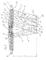
- Fig. 1 shows a perspective view of an embodiment of the surgical lamp according to the invention 1.
- the surgical light 1 comprises a support system 2, a suspension device 3 and a lamp body 4.
- the support system 2 is attached to a ceiling, a wall or a mobile stand.
- the lamp body 4 can be positioned within the radius of action in any spatial position and orientation.
- a light exit opening is arranged on almost the entire surface, which is directed in operation to a surgical field which is located at a certain distance.
- each a handle 5, 6 attached to the two halves of the lamp body 4.
- the two halves of the lamp body are rotatably connected to each other, so that when pivoting the one half, the other half moves to keep the light exit surfaces always in a plane.
- control device 7 is arranged within the lamp body 4, a control device 7 is arranged.
- the control device 7 does not necessarily have to be arranged in the lamp body 4, but can also be accommodated in a separate housing which is arranged on the lamp body 4 or on the suspension device 3.
- the control device 7 is located in an external operating unit, not shown, which is located in a medical supply unit or in / on a wall.
- an operating device 8 is arranged on the outside of the lamp body 4, on the suspension device 3 or in a medical supply unit or in / on a wall.
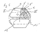
- Fig. 2 is a sectional view of the lamp body 4 with light sources with light beams whose axes intersect with the central axis and with light sources whose light beams whose axes do not intersect with the central axis.
- a plurality of lighting means 9, 9 ', 9'' is provided in the lamp body 4.
- the lamp body 4 has a central axis 12 which is perpendicular to a plane in which the lighting means 9 are arranged.
- the lighting means 9, 9 ', 9'' are arranged annularly or in accordance with the shape of the lamp body 4.
- Each lamp 9, 9 ', 9'' is equipped with a device for bundling the light, here a refractor 10.
- the separate refractors 10 instead of the separate refractors 10 also separate reflectors or bulbs can be used with integrated means for bundling the light.
- the bundled light of the luminous means 9, on the one hand emerges from the refractor 10 in each case in a light beam I, I ', which each has an axis a, a'.
- the light beam I, I ' illuminates an entire light field 11, respectively.
- the lighting means 9 are mounted on inclined mounting surfaces 19 having a vertical axis which is parallel to the axis a, a '.
- the bulbs 9 with the refractors 10 are arranged inclined, so that the axes a, a 'of the light beam I, I' intersect the central axis 12 at an intersection point 13.
- intersection point in the description should be understood to mean that this is not a geometrically exact point but an area in which the axes intersect, with the photometric properties being within a normal tolerance range of an optimal intersection point.
- the area corresponds to a sectional area with a plane perpendicular to the central axis at a distance 1.
- the light beam I, I 'form in a plane which is at a distance 1, perpendicular to the central axis 12, depending on a light field.
- the point of intersection 13 is the point of intersection of the two axes a, a 'with the central axis 12, so that the two luminous fields coincide and together form the luminous field 11 and is defined as a focal point.
- the light field 11 has a certain diameter D and a defined distribution of the light intensity over the diameter of the light field, the normative is predetermined.
- the superposed light beams I, I 'form an approximately circular illuminated field.
- Fig. 2 two light sources 9 are shown, which form the central light field 11.
- the light field 11 is formed by a group of light beam bundles I, I ', which are emitted by the light sources 9, which are distributed uniformly over the light exit surface.
- the bulbs 9 with the refractors 10 are arranged inclined so that the axes a, a 'of the light beam I, I' intersect at the intersection 13, the central axis.
- the lighting means 9 are evenly distributed in the plane to an obstacle, which is introduced between the lamp body 4 and the surgical field and thereby interrupts a light beam, which has a shadowing result, to undercut and thus prevent or mitigate the shadowing.
- the bundled light of the lighting means 9 'and 9 ", respectively, also emerges from the refractor 10 in a light beam bundle II or III, each having an axis b and c, respectively, in order to form a light field which is not arranged centrally.
- the bulbs 9 ', 9''with the refractors 10 are arranged inclined so that the axes b, c of the light beam II, III do not intersect the central axis 12.
- the axes b, c are projected into the plane of the drawing, and the extrapolated axes are therefore shown intersecting the central axis in this plane.
- the axes b, c do not intersect the central axis (see Fig. 4 ).
- the lighting means 9 ', 9' ' are mounted on inclined mounting surfaces 19, each having a vertical axis, which are parallel to the axis b, c.
- the light beam II, III form in a plane which is at a distance 1, perpendicular to the central axis 12, respectively, a light field 14, 15.
- the bulbs 9 ', 9' 'with the refractors 10 are arranged so that the light fields 14th , 15 partially overlap to obtain a uniform brightness distribution.
- Fig. 2 is only ever a light source 9 ', 9''shown, each forming a light field 14, 15.
- the light field 14, 15 is formed by a bevy of light beams II, III, which are emitted by other light sources not shown 9 ', 9'', and which are also distributed evenly in the plane to an obstacle between the lamp body 4 and the surgical field is introduced and thereby interrupts a light beam, which has the consequence of shading, to undercut and thus prevent or mitigate the shadowing.
- the light beams II for the light field 14 intersect at an intersection 17 and the light beams III for the light field 15 intersect at an intersection point 18.
- the lighting means 9 are formed in this embodiment by LEDs, but can also be designed as halogen lamps or gas discharge lamps, optionally with color filters.
- the control device 7 has means for dimming and switching on and off the lighting means 9 9 ', 9' ', as e.g. Current controller, means for transmitting switching and setting information of the switching and setting elements of the operating device 8, a memory area for storing operating parameters and a CPU, from the switching and setting information, based on the stored operating parameters, the required settings for the means for Dimming and switching on and off of the bulbs 9, 9 ', 9' 'calculated or determined on.
- the control device 7 has means for dimming and switching on and off the lighting means 9 9 ', 9' ', as e.g. Current controller, means for transmitting switching and setting information of the switching and setting elements of the operating device 8, a memory area for storing operating parameters and a CPU, from the switching and setting information, based on the stored operating parameters, the required settings for the means for Dimming and switching on and off of the bulbs 9, 9 ', 9' 'calculated or determined on.
- the control device 7 is connected to the lighting means 9, 9 ', 9 ", which are controlled in groups
- a group is formed from a plurality of light sources 9, 9', 9", respectively, which are driven with the same performance parameters.
- the individual groups consist in each case only of light sources 9 whose light beams I, I 'have the same intersection point 13, from light sources 9' whose light beams II have the same intersection point 17, or from light sources 9 '' whose light beams III have the same intersection point 18 to have. But there are several groups of each of the light sources 9, and the light sources 9 'and the light sources 9 "possible.
- the on / off switching element switches the operation light 1 from a standby mode in which the bulbs 9 are not lit to an operation mode.
- the lighting means 9 are operated according to the setting of the adjusting elements. For complete shutdown by switching off the power supply not shown external main switch is provided.
- the element for setting the shape of the luminous field gives to the control device 7 the setting information about the set luminous field shape of the operation light 1. If a round luminous field is set, the means for dimming and switching on and off are then controlled by the control device 7 so that only the Illuminants are operated, which have an intersection with the central axis 12.
- the light intensity distribution adjustment element in the light field gives to the control device 7 the setting information about the set light intensity distribution of the operation light 1. If a standard light intensity distribution is set, the means for dimming and turning on and off are controlled by the control device 7 so that only the light source distribution means Illuminant 9 are operated, the intersection point of which are located on the central axis 12.
- bulbs can be used which are equipped with Lichtbündelvorvorungsungsvoriquessvorraumen that produce no standard light intensity distribution.
- the light intensity distribution can be adjusted so that the outer edge of the light field is more illuminated and the center is lower.
- the light beams I, I ' can then be set a desired light intensity distribution, depending on the intensity of the two different types of light beams. (please refer Fig. 6 )
- the performance parameters are determined and stored empirically.
- the element for setting the distance gives to the control device 7 the information as to which distance of the illuminated field 11 of the lamp body 4, the operating light to be set.
- the lighting means 9 In operation at a set distance 1 of the lamp body from the intersection 13, to which the light sources are directed with the light beams I, I 'in the present embodiment by the control device 7, the lighting means 9 are driven, the axis a, a' of the light rays I, I 'are directed to the intersection 13 and thus the approximately circular illuminated field 11 is formed.
- the lighting means 9 When setting a different distance alternative bulbs, whose distance between the lamp body and the intersection of the axes of their light beams corresponds to the set distance, controlled.
- the illuminated field fulfills the normative specifications regarding the distribution of light intensity in the illuminated field.
- the brightness adjustment element gives to the control device 7 the setting information about the set total brightness of the operation light 1.
- the means for dimming and turning on and off are then controlled by the control device 7 so that the distribution of brightness of the individual light sources 9 remains unchanged and only the overall brightness is changed.
- the operating parameters for the brightness settings are determined empirically and stored in the memory area of the control device 7.
- the operating light 1 comprises a distance sensor for measuring the distance between By detecting the distance of the lamp body 4 from the operation site and relaying the distance information to the control device 7, the control device 7 is capable of detecting the point with the maximum resultant Adjust brightness in the distance of the lamp body 7 from the surgical site, so that the surgical site is illuminated with the greatest brightness.
- the operating light 1 comprises a brightness sensor, which measures the brightness in the surgical site, and means for passing the brightness information to the control device 7.
- the control device 7 By detecting the brightness, wherein one possibility is to detect the brightness in the center of the light field, and another way to detect the average brightness in the entire light field, and passing the brightness information to the control device 7, the control device 7 is able to set the point with the maximum resulting brightness in the distance of the lamp body 4 so that the operation site at a change in the distance of the lamp body 4 is illuminated from the surgical site with the same brightness in the respective detection space.
- Fig. 3 shows a schematic plan view of a lamp body 4 with an arrangement of lighting means 9, of which intersect the axes A, A 'of the light beams I, I' of the operating lights 9 with the central axis.
- the entire light exit surface ie the lower side of both halves of the lamp body 4, is provided with lighting means 9 with the exception of a narrow edge region (here are only five Illuminant 9 shown). In this case, only those are in operation whose axis a, a 'intersects with the central axis 12 by these light beams I, I', a circular illuminated field 11 is formed.
- Fig. 4 shows a schematic plan view of a lamp body 4 with an arrangement of lighting means 9, of which the axes b, c of the light beams II, III of the operating lights 9 do not intersect with the central axis 12. In this case, mainly those are in operation whose axis b, c does not intersect with the central axis 12.
- illuminants 9 can also be in operation in which the axes a, a 'of the light rays I, I' intersect with the central axis 12 (see FIG Fig. 3 ). The remaining area is illuminated by further light sources 9 whose light beams do not intersect with the central axis 12.
- Fig. 5 shows a distribution of light intensity in a plane which is located at a distance of one meter perpendicular to the central axis 12. Above the diameter of the luminous field, the light intensity is here applied to luminous means 9 with light bundling means 10, which produce a standard-compliant luminous field.
- the solid line represents the distribution of the luminous intensity over a diameter D of the luminous field. This course is achieved when the axes of all the light beams intersect at the point of intersection 13.
- the above normative requirements are met.
- the overall brightness is set by the proportionate power setting of the respective lamps.
- Fig. 6 shows a distribution of the light intensity over the diameter of the light field with a light beam means, which is a standard-compliant light field, and light beam means which produce no standard-compliant light field.
- the dashed line shows the luminous intensity distribution in a luminous field that is not standard.
- the overall brightness is also set here by the proportionate power setting of the respective bulbs.
- the settings for the operating parameters for a standardized light field distribution and a light field distribution with the same brightness over the entire light field are stored in the memory area of the control device (7). However, it is also possible to store any light field distribution by the user.
Landscapes
- Health & Medical Sciences (AREA)
- Engineering & Computer Science (AREA)
- Surgery (AREA)
- Life Sciences & Earth Sciences (AREA)
- General Engineering & Computer Science (AREA)
- Public Health (AREA)
- Nuclear Medicine, Radiotherapy & Molecular Imaging (AREA)
- Biomedical Technology (AREA)
- Heart & Thoracic Surgery (AREA)
- Medical Informatics (AREA)
- Molecular Biology (AREA)
- Animal Behavior & Ethology (AREA)
- General Health & Medical Sciences (AREA)
- Oral & Maxillofacial Surgery (AREA)
- Pathology (AREA)
- Veterinary Medicine (AREA)
- Non-Portable Lighting Devices Or Systems Thereof (AREA)
- Circuit Arrangement For Electric Light Sources In General (AREA)
- Materials For Medical Uses (AREA)
- Lighting Device Outwards From Vehicle And Optical Signal (AREA)
- Eye Examination Apparatus (AREA)
- Dry Shavers And Clippers (AREA)
- Endoscopes (AREA)
Description
- Die Erfindung betrifft eine Operationsleuchte mit einem in der Größe und in der Form veränderlichen Leuchtfeld und einer verstellbaren Lichtstärkeverteilung im Leuchtfeld.
- Operationsleuchten unterliegen weltweit der internationalen Norm IEC 60601-2-41. In dieser Norm sind unter anderem die lichttechnischen Anforderungen von Operationsleuchten festgelegt. Neben den Eigenschaften der Farbtemperatur, der Helligkeit und Strahlungsgrenzwerten ist auch die Verteilung der Helligkeit in dem Leuchtfeld festgelegt. Dabei ist in einem Abstand von einem Meter zwischen dem Leuchtenkörper und der Operationsebene, die Verringerung der Helligkeit mit größer werdenden Abstand vom Zentrum des Leuchtfelds so definiert, dass der Durchmesser, bei dem 50% der maximalen Helligkeit vorhanden sind, mindestens halb so groß sein muss, wie der Durchmesser, bei dem 10% der maximalen Helligkeit vorhanden sind.
- Eine Möglichkeit der Ausführung von Operationsleuchten zur Erfüllung dieser Anforderungen sind so genannte Großspiegelleuchten. Hierbei ist die Lichtquelle eine Halogenlampe oder Gasentladungslampe, die im Brennpunkt eines großen Reflektors mit einem Durchmesser von ca. 500 mm bis 1000 mm angeordnet ist. Durch eine Verschiebung der Lichtquelle auf der Mittelachse des Reflektors, und damit mehr oder weniger aus dem, oder in den optimalen Brennpunkt des Reflektors, wird der Durchmesser des Leuchtfelds, d.h. der beleuchtete Durchmesser im Operationsfeld vergrößert oder verkleinert und der Fokuspunkt verändert, d.h. der Abstand der hellsten beleuchteten Stelle, in der sich die reflektierten Lichtstrahlen schneiden, von dem Leuchtenkörper der Operationsleuchte auf einer Mittelachse des Leuchtenkörpers verändert. Die Form des Leuchtfelds ist hier kreisrund und konstruktionsbedingt nicht veränderbar.
- Eine andere Ausführung sind aufgelöste Lichtsysteme. Hierbei umfasst die Operationsleuchte in der Regel einen zentralen Scheinwerfer oder ein zentrales Lichtmodul, der/das starr am Leuchtenkörper befestigt ist und mehrere Scheinwerfer oder Lichtmodule in einer ringförmigen Anordnung um den zentralen Scheinwerfer oder das zentrale Lichtmodul. Die Veränderung der Richtung des Lichtaustritts aus den äußeren Scheinwerfern oder Lichtmodulen ist über radial verschwenkbare Leuchtmittel oder Reflektoren realisiert, oder die gesamten Scheinwerfer oder Lichtmodule sind radial schwenkbar verstellbar. Die Form des Leuchtfelds ist dabei in der Weise veränderbar, dass bei einer idealen Fokussierung das Leuchtfeld kreisrund ist und bei einer Defokussierung, das heißt, wenn sich die Mittelachsen der äußeren Scheinwerfer in einem Punkt schneiden, der nicht in der Operationsebene liegt, mit einer Vergrößerung des Abstands des Fokuspunkts von der Operationsebene mehr und mehr in eine Form übergeht, die der Anordnung der äußeren Scheinwerfer entspricht. Die Verteilung der Lichtstärke entwickelt sich mit größer werdendem Abstand zwischen dem Fokuspunkt und der Operationsebene weg von einer konzentrischen Lichtverteilung, hin zu einer Lichtverteilung, in der sich die Strahlenbündel der äußeren Scheinwerfer im Leuchtfeld abbilden.
- Eine weitere Art von Operationsleuchten ist ohne die Verstellmöglichkeit des Leuchtfelddurchmessers und des Abstands des Fokuspunkts ausgeführt. Hierbei sind die lichttechnischen Daten, Leuchtfelddurchmesser und Fokuspunkt für einen Arbeitspunkt optimal eingestellt. Die Form des Leuchtfelds ist kreisrund. Bei aufgelösten Lichtsystemen besteht die Gefahr, dass bei einer Veränderung des Abstands zwischen dem Leuchtenkörper und der Operationsebene, das Leuchtfeld nicht mehr homogen wirkt, sondern sich, wie bei dem oben beschriebenen aufgelösten Lichtsystem, bei größerem Abstand des Fokuspunkts von der Operationsstelle, einzelne Lichtpunkte in der Operationsstelle abbilden.
- Die Verteilung der Lichtstärke im Leuchtfeld kann durch Zu- und Abschalten von einzelnen Leuchtmittel, die ihr Licht zentrisch zum Mittelpunkt des Leuchtfelds abgeben, verändert werden.
- So zeigt beispielsweise die
EP-A-1 568 934 eine Operationsleuchte mit separat zuschaltbaren Leuchtmitteln zur verstärkten Ausleuchtung des Zentrums des Leuchtfelds, die OffenlegungEP 1 568 934 eine Operationsleuchte mit ausschaltbaren Leuchtmitteln im Zentrum des Leuchtfelds zur Vermeidung von Schattenbildung, und dieEP-A-1 722 157 eine Operationsleuchte mit konzentrischen Bereichen mit Leuchtmitteln, die unabhängig voneinander eingeschaltet und gedimmt werden können, um Schattenbildung zu vermeiden und verschiedene Typen von Operationswunden (enge, tiefe Wunde oder großflächige Wunde) optimal auszuleuchten. Sämtliche Druckschriften zeigen aber im Arbeitspunkt, d.h. bei optimalem Abstand zwischen dem Leuchtenkörper und der Operationsebene, kreisrunde Leuchtfelder. - Die Veröffentlichung
EP-A-1 433 998 offenbart eine Operationsleuchte mit einzelnen Lichtmodulen, deren Achsen der Lichtstrahlbündel parallel sind und die Leuchtfelder der Lichtstrahlbündel sich teilweise überlappen und so eine Leuchtfeldform ergeben, die sich im Wesentlichen aus der Form des Leuchtenkörpers ergibt. Einzelne Lichtmodule werden zur Vermeidung von Schattenbildung automatisch ausgeschaltet oder gedimmt. Die Form des Leuchtfelds ist unveränderlich. - Die Patentanmeldung
EP-A-1 938 768 zeigt eine Operationsleuchte mit einer Gruppe von Haupt-Leuchtmitteln, die jeweils einen gebündelten Lichtstrahl aufweisen, die sich auf einem Punkt im Zentrum des Leuchtfelds schneiden, der einen Meter vom Leuchtenkörper entfernt ist, und eine weitere Gruppe von Zusatz-Leuchtmitteln, die zwischen den Haupt-Leuchtmitteln angeordnet sind und deren Lichtstrahlen Achsen aufweisen, die einen konzentrischen ringförmigen Lichtstrahl mit einem Durchmesser von 100 bis 200mm um den Lichtstrahl der Haupt-Leuchtmittel bilden. Die Leuchtmittel beider Gruppen sind jeweils mit einer Steuerung verbunden. - Die Patentschrift
US 5,068,767 offenbart eine Operationsleuchte mit einer automatischen Fokuspunkteinstellvorrichtung. Ein Sensor, der die vom Operationsgebiet reflektierte Lichtmenge misst, gibt die Werte an eine Steuerung, die den Neigungswinkel von Lichtquellen bestimmt welcher durch Motoren so eingestellt wird. Dabei sind die optischen Achsen der Lichtquellen immer auf einen Punkt fokussiert. - Es ist Aufgabe der Erfindung, eine Operationsleuchte zur Verfügung zu stellen, die kostengünstig die Möglichkeit bietet, die Leuchtfeldform und die Verteilung der Lichtstärke im Leuchtfeld zu verändern.
- Die Aufgabe wird mit den Merkmalen des Anspruchs 1 gelöst. Weiterbildungen der Erfindung sind in den Unteransprüchen beschrieben.
- Die Operationsleuchte bietet durch eine spezielle Anordnung und Ansteuerung der Leuchtmittel die Möglichkeit, die Leuchtfeldform und die Lichtstärkeverteilung im Leuchtfeld zu verändern. Dies erfolgt ohne mechanische Verstellmittel.
- Weitere Merkmale und Zweckmäßigkeiten der Erfindung werden anhand eines Ausführungsbeispiels unter Bezugnahme auf die beigefügten Zeichnungen erläutert.
- Fig. 1
- ist eine perspektivische Ansicht eines Ausführungsbei- spiels der erfindungsgemäßen Operationsleuchte.
- Fig. 2
- ist eine Schnittansicht eines Leuchtenkörpers mit Lichtstrahlen, die sich mit der Mittelachse schneiden und mit Lichtstrahlen, die sich mit der Mittelachse nicht schneiden.
- Fig. 3
- zeigt eine schematische Draufsicht eines Leuchtenkör- pers mit einer Anordnung von Leuchtmitteln, von denen sich die Achsen der Lichtstrahlen der sich in Betrieb befindlichen Leuchtmittel mit der Mittelachse schnei- den.
- Fig. 4
- zeigt eine schematische Draufsicht eines Leuchtenkör- pers mit einer Anordnung von Leuchtmitteln, von denen sich die Achsen der Lichtstrahlen der sich in Betrieb befindlichen Leuchtmittel mit der Mittelachse nicht schneiden.
- Fig. 5
- zeigt ein Diagramm mit einer Verteilung der Lichtstär- ke über dem Durchmesser des Leuchtfelds mit Lichtbün- delungsmitteln, die ein normgerechtes Leuchtfeld er- zeugen.
- Fig. 6
- zeigt ein Diagramm mit einer Verteilung der Lichtstär- ke über dem Durchmesser des Leuchtfelds mit Lichtbün- delungsmitteln, die ein normgerechtes Leuchtfeld und Lichtbündelungsmitteln, die kein normgerechtes Leucht- feld erzeugen
-
Fig. 1 zeigt eine perspektivische Ansicht eines Ausführungsbeispiels der erfindungsgemäßen Operationsleuchte 1. Die Operationsleuchte 1 umfasst ein Tragsystem 2, eine Aufhängevorrichtung 3 und einen Leuchtenkörper 4. Das Tragsystem 2 wird an einer Raumdecke, einer Wand oder einem fahrbaren Ständer befestigt. Durch das Tragsystem 2 und die Aufhängevorrichtung 3 ist der Leuchtenkörper 4 innerhalb des Aktionsradius in jeder beliebigen räumlichen Stellung und Orientierung positionierbar. Auf der nicht gezeigten, gegenüberliegenden Seite des Leuchtenkörpers 4 ist auf nahezu der gesamten Fläche eine Lichtaustrittsöffnung angeordnet, die im Betrieb auf ein Operationsfeld, das sich in einem bestimmten Abstand befindet, gerichtet ist. - Zum unsterilen Positionieren des Leuchtkörpers 4 sind an den beiden Hälften des Leuchtenkörpers 4 je ein Griff 5, 6 angebracht. Die beiden Hälften des Leuchtenkörpers sind drehfest miteinander verbunden, so dass sich beim Verschwenken der einen Hälfte die andere Hälfte mit bewegt, um die Lichtaustrittsflächen immer in einer Ebene zu halten.
- Innerhalb des Leuchtenkörpers 4 ist eine Steuerungsvorrichtung 7 angeordnet. Die Steuerungsvorrichtung 7 muss nicht zwingend in dem Leuchtenkörper 4 angeordnet sein, sondern kann auch in einem separaten Gehäuse, das am Leuchtenkörper 4 oder an der Aufhängevorrichtung 3 angeordnet ist, untergebracht sein. Alternativ besteht auch die Möglichkeit, dass sich die Steuerungsvorrichtung 7 in einer nicht gezeigten externen Bedieneinheit befindet, die sich in einer Medizinischen Versorgungseinheit oder in/an einer Wand befindet.
- An der Außenseite des Leuchtenkörpers 4 ist eine Bedienvorrichtung 8 angeordnet. Die Bedienvorrichtung 8 kann sich aber auch in einem separaten Gehäuse befinden, das sich beispielsweise am Leuchtenkörper 4, an der Aufhängevorrichtung 3 oder in einer Medizinischen Versorgungseinheit oder in/an einer Wand befindet.
-
Fig. 2 ist eine Schnittansicht des Leuchtenkörpers 4 mit Leuchtmitteln mit Lichtstrahlenbündeln, deren Achsen sich mit der Mittelachse schneiden und mit Leuchtmitteln, deren Lichtstrahlenbündeln, deren Achsen sich mit der Mittelachse nicht schneiden. - In dem Leuchtenkörper 4 ist eine Mehrzahl von Leuchtmitteln 9, 9', 9'' vorgesehen. Der Leuchtenkörper 4 hat eine Mittelachse 12, die senkrecht auf einer Ebene steht, in der die Leuchtmittel 9 angeordnet sind. Die Leuchtmittel 9, 9', 9'' sind ringförmig oder entsprechend der Form des Leuchtenkörpers 4 angeordnet. Jedes Leuchtmittel 9, 9', 9'' ist mit einer Vorrichtung zum Bündeln des Lichts, hier einem Refraktor 10, ausgestattet. Anstelle der separaten Refraktoren 10 können auch separate Reflektoren oder Leuchtmittel mit integrierten Mitteln zum Bündeln des Lichts verwendet werden.
- Das gebündelte Licht der Leuchtmittel 9, tritt einerseits jeweils in einem Lichtstrahlbündel I, I' aus dem Refraktor 10 aus, das jeweils eine Achse a, a' besitzt. Das Lichtstrahlbündel I, I' beleuchtet jeweils ein gesamtes Leuchtfeld 11.
- Die Leuchtmittel 9 sind auf geneigten Befestigungsflächen 19 befestigt, die eine senkrechte Achse aufweisen, die parallel zu der Achse a, a' ist. Die Leuchtmittel 9 mit den Refraktoren 10 sind geneigt angeordnet, so dass die Achsen a, a' der Lichtstrahlbündel I, I' die Mittelachse 12 in einem Schnittpunkt 13 schneiden.
- Ein Schnittpunkt ist in der Beschreibung so zu verstehen, dass dies kein geometrisch exakter Punkt ist, sondern ein Bereich in dem sich die Achsen schneiden, wobei sich die lichttechnischen Eigenschaften in einem üblichen Toleranzbereich eines optimalen Schnittpunkts befinden. Der Bereich entspricht einer Schnittfläche mit einer Ebene senkrecht zu Mittelachse in einem Abstand 1.
- Die Lichtstrahlbündel I, I' bilden in einer Ebene, die in einem Abstand 1, senkrecht zur Mittelachse 12 liegt, je ein Leuchtfeld. Der Schnittpunkt 13 ist der Schnittpunkt beider Achsen a, a' mit der Mittelachse 12, so dass die beiden Leuchtfelder zur Deckung kommen und gemeinsam das Leuchtfeld 11 bilden und wird als ein Fokuspunkt definiert. Das Leuchtfeld 11 besitzt einen bestimmten Durchmesser D und eine definierte Verteilung der Lichtstärke über den Durchmesser des Leuchtfelds, die normativ vorgegeben ist. Die überlagerten Lichtstrahlen I, I' bilden ein annähernd kreisrundes Leuchtfeld.
- In
Fig. 2 sind zwei Leuchtmittel 9 gezeigt, die das zentrale Leuchtfeld 11 bilden. Das Leuchtfeld 11 wird durch eine Schar von Lichtstrahlbündeln I, I' gebildet, die von den Leuchtmitteln 9 ausgestrahlt werden, die gleichmäßig über die Lichtaustrittsfläche verteilt sind. Die Leuchtmittel 9 mit den Refraktoren 10 sind so geneigt angeordnet, dass die Achsen a, a' der Lichtstrahlbündel I, I' im Schnittpunkt 13 die Mittelachse schneiden. - Die Leuchtmittel 9 sind in der Ebene gleichmäßig verteilt, um ein Hindernis, das zwischen den Leuchtenkörper 4 und das Operationsfeld eingebracht wird und dadurch ein Lichtstrahlenbündel unterbricht, was eine Schattenbildung zur Folge hat, zu unterleuchten und somit die Schattenbildung zu verhindern oder abzuschwächen.
- Das gebündelte Licht der Leuchtmittel 9' bzw. 9", tritt auch jeweils in einem Lichtstrahlbündel II bzw. III aus dem Refraktor 10 aus, das jeweils eine Achse b bzw. c besitzt, um ein Leuchtfeld zu bilden, das nicht zentral angeordnet ist.
- Die Leuchtmittel 9', 9'' mit den Refraktoren 10 sind so geneigt angeordnet, dass die Achsen b, c der Lichtstrahlbündel II, III die Mittelachse 12 nicht schneiden. In der Ansicht der
Fig. 2 werden die Achsen b, c in die Zeichnungsebene projiziert und die extrapolieren Achsen sind aus diesem Grund so dargestellt, dass sie in dieser Ebene die Mittelachse schneiden. In einer räumlichen Darstellung oder einer Projektion in eine andere Ebene ist ersichtlich, dass die Achsen b, c die Mittelachse nicht schneiden (sieheFig. 4 ). - Die Leuchtmittel 9', 9'' sind auf geneigten Befestigungsflächen 19 befestigt, die jeweils eine senkrechte Achse aufweisen, die parallel zu der Achse b, c sind.
- Die Lichtstrahlbündel II, III bilden in einer Ebene, die in einem Abstand 1, senkrecht zur Mittelachse 12 liegt, jeweils ein Leuchtfeld 14, 15. Die Leuchtmittel 9', 9'' mit den Refraktoren 10 sind so angeordnet, dass sich die Leuchtfelder 14, 15 teilweise überlagern, um eine gleichmäßige Helligkeitsverteilung zu erlangen.
- In
Fig. 2 ist nur je ein Leuchtmittel 9', 9'' gezeigt, das jeweils ein Leuchtfeld 14, 15 bilden. Das Leuchtfeld 14, 15 wird aber durch eine Schar von Lichtstrahlbündeln II, III gebildet, die von weiteren nicht gezeigten Leuchtmitteln 9', 9'' ausgestrahlt werden, und die ebenfalls in der Ebene gleichmäßig verteilt sind, um ein Hindernis, das zwischen dem Leuchtenkörper 4 und das Operationsfeld eingebracht wird und dadurch ein Lichtstrahlenbündel unterbricht, was eine Schattenbildung zur Folge hat, zu unterleuchten und somit die Schattenbildung zu verhindern oder abzuschwächen. Die Lichtstrahlen II für das Leuchtfeld 14 schneiden sich in einem Schnittpunkt 17 und die Lichtstrahlen III für das Leuchtfeld 15 schneiden sich in einem Schnittpunkt 18. - Bei der Verwendung von mehreren Leuchtmitteln 9, 9', 9'' die jeweils auf das Leuchtfeld 11, 17, 18 gerichtet sind, können verschiedenfarbige Leuchtmittel 9, 9', 9'' verwendet werden. Dabei besteht die Möglichkeit, die resultierende Farbtemperatur des Lichts in einem bestimmten Farbtemperaturbereich einzustellen. Die Leuchtmittel 9 werden in diesem Ausführungsbeispiel durch LEDs gebildet, können aber auch als Halogenlampen oder Gasentladungslampen, ggf. mit Farbfiltern ausgebildet sein.
- Im Leuchtenkörper 4 ist die nicht gezeigte Steuerungsvorrichtung 7 angeordnet. Die Steuerungsvorrichtung 7 weist Mittel zum Dimmen und Ein- und Ausschalten der Leuchtmittel 9 9', 9'', wie z.B. Stromregler, Mittel zum Übertragen von Schalt- und Einstellinformationen der Schalt- und Einstellelemente der Bedienvorrichtung 8, einen Speicherbereich zum Abspeichern von Betriebsparametern und eine CPU, die aus den Schalt- und Einstellinformationen, an Hand der abgespeicherten Betriebsparameter, die erforderlichen Einstellungen für die Mittel zum Dimmen und Ein- und Ausschalten der Leuchtmittel 9, 9', 9'' berechnet oder bestimmt, auf.
- Die Steuerungsvorrichtung 7 ist mit den Leuchtmitteln 9, 9', 9" verbunden, die gruppenweise angesteuert werden. Eine Gruppe wird aus mehreren Leuchtmitteln 9, bzw. 9', bzw. 9" gebildet, die mit den gleichen Leistungsparametern angesteuert werden. Die einzelnen Gruppen bestehen jeweils nur aus Leuchtmitteln 9, deren Lichtstrahlen I, I' den gleichen Schnittpunkt 13 haben, aus Leuchtmitteln 9', deren Lichtstrahlen II den gleichen Schnittpunkt 17 haben, oder aus Leuchtmitteln 9'', deren Lichtstrahlen III den gleichen Schnittpunkt 18 haben. Es sind aber mehrere Gruppen aus jeweils den Lichtquellen 9, bzw. den Lichtquellen 9' bzw. den Lichtquellen 9" möglich.
- Die Steuerungsvorrichtung 7 ist ebenfalls mit der Bedienvorrichtung 8 verbunden. An der Bedienvorrichtung 8 ist
- ein Element zum Ein-/Ausschalten,
- ein Element zur Einstellung der Form des Leuchtfelds,
- ein Element zur Einstellung der Lichtstärkeverteilung im Leuchtfeld,
- ein Element zur Abstandseinstellung, und
- ein Element zur Helligkeitseinstellung vorgesehen.
- Das Element zum Ein-/Ausschalten schaltet die Operationsleuchte 1 von einem Standby-Modus, in der die Leuchtmittel 9 nicht leuchten, in einen Betriebsmodus. Dabei werden die Leuchtmittel 9 entsprechend der Einstellung der Einstellelemente betrieben. Zum vollständigen Ausschalten durch Abschalten der Stromversorgung ist ein nicht gezeigter externer Hauptschalter vorgesehen.
- Das Element zur Einstellung der Form des Leuchtfelds gibt an die Steuerungsvorrichtung 7 die Einstellinformation über die eingestellte Leuchtfeldform der Operationsleuchte 1. Ist ein rundes Leuchtfeld eingestellt, werden die Mittel zum Dimmen und Ein- und Ausschalten von der Steuerungsvorrichtung 7 dann so gesteuert, dass nur die Leuchtmittel betrieben werden, die einen Schnittpunkt mit der Mittelachse 12 haben.
- Ist ein anderes, als ein rundes Leuchtfeld eingestellt, sind in dem Speicherbereich der Steuerungsvorrichtung 7 verschiedene Situationen abgespeichert. So können in einer Situation diejenigen Leuchtmittel 9, 9', 9''betrieben werden, die durch die Überlagerung ihrer einzelnen Leuchtfelder insgesamt, ein im Wesentlichen rechteckiges Leuchtfeld 16' bilden. Alternativ sind auch ovale Leuchtfelder, hundeknochenförmige Leuchtfelder oder dreieckige Leuchtfelder abgespeichert. Optional besteht auch die Möglichkeit, dass beliebige Leuchtfelder im Speicherbereich abgespeichert werden können. Ebenso sind die Abmessungen der Leuchtfelder, Länge und Breite einstellbar.
- Das Element zur Einstellung der Lichtstärkeverteilung im Leuchtfeld gibt an die Steuerungsvorrichtung 7 die Einstellinformation über die eingestellte Lichtstärkeverteilung der Operationsleuchte 1. Ist eine normgerechte Lichtstärkeverteilung eingestellt, werden die Mittel zum Dimmen und Ein- und Ausschalten von der Steuerungsvorrichtung 7 dann so gesteuert, dass nur die Leuchtmittel 9 betrieben werden, deren Schnittpunkt sich auf der Mittelachse 12 befinden.
- Für eine Veränderung der Lichtverteilung im runden Leuchtfeld 11 werden zusätzliche Leuchtmittel 9 mit Lichtstrahlen mit einer Achse betrieben, deren Schnittpunkte auf der Mittelachse 12 liegen, aber nicht in dem Schnittpunkt 13. Somit vergrößert sich durch die Veränderung der Lichtstärkeverteilung auch der Durchmesser des Leuchtfelds leicht. (siehe
Fig. 5 ) - Alternativ können auch Leuchtmittel eingesetzt werden, die mit Lichtbündelungsvorrichtungsvorrichtungen ausgerüstet sind, die keine normgerechte Lichtstärkeverteilung erzeugen. Somit kann z.B. das Lichtstärkeverteilung so eingestellt werden, dass der äußere Rand des Leuchtfelds stärker beleuchtet wird und das Zentrum geringer. Durch Überlagerung dieser Lichtstrahlen, deren Achsen auch auf den Schnittpunkt 13 gerichtet sind, mit den Lichtstrahlen I, I' kann dann eine gewünschte Lichtstärkeverteilung, je nach Intensität der beiden verschiedenartigen Lichtstrahlen eingestellt werden. (siehe
Fig. 6 ) - Für die Lichtstärkeverteilung in einem Leuchtfeld mit einer anderen Form als einer runden, werden die Leistungsparameter empirisch ermittelt und abgespeichert.
- Das Element zur Abstandseinstellung gibt an die Steuerungsvorrichtung 7 die Information, auf welchen Abstand des Leuchtfelds 11 vom Leuchtenkörper 4 die Operationsleuchte eingestellt werden soll.
- Im Betrieb bei einem eingestellten Abstand 1 des Leuchtenkörpers vom Schnittpunkt 13, auf den die Leuchtmittel mit den Lichtstrahlen I, I' gerichtet sind, werden im vorliegenden Ausführungsbeispiel durch die Steuerungsvorrichtung 7 die Leuchtmittel 9 angesteuert, deren Achse a, a' der Lichtstrahlen I, I' auf den Schnittpunkt 13 gerichtet sind und somit wird das annähernd kreisrunde Leuchtfeld 11 gebildet. Bei der Einstellung eines anderen Abstands werden alternative Leuchtmittel, deren Abstand zwischen dem Leuchtenkörper und dem Schnittpunkt der Achsen ihrer Lichtstrahlen dem eingestellten Abstand entspricht, angesteuert.
- Bei den Einstellungen, in der der eingestellte Abstand einem Meter entspricht, erfüllt das Leuchtfeld die normativen Vorgaben bezüglich der Lichtstärkeverteilung im Leuchtfeld.
- Das Element zur Helligkeitseinstellung gibt an die Steuerungsvorrichtung 7 die Einstellinformation über die eingestellte Gesamthelligkeit der Operationsleuchte 1. Die Mittel zum Dimmen und Ein- und Ausschalten werden von der Steuerungsvorrichtung 7 dann so gesteuert, dass die Verteilung der Helligkeit der einzelnen Leuchtmittel 9 unverändert bleibt und nur die Gesamthelligkeit verändert wird.
- Die Betriebsparameter für die Helligkeitseinstellungen werden empirisch ermittelt und im Speicherbereich der Steuerungsvorrichtung 7 abgespeichert.
- In einer alternativen Ausführungsform umfasst die Operationsleuchte 1 einen Abstandssensor zum Messen des Abstands zwischen dem Leuchtenkörper 4 und der Operationsstelle und Mittel zur Weitergabe des Abstands an die Steuerungsvorrichtung 7. Durch die Erfassung des Abstands des Leuchtenkörpers 4 von der Operationsstelle und Weitergabe der Abstandsinformation an die Steuerungsvorrichtung 7 ist die Steuerungsvorrichtung 7 in der Lage, den Punkt mit der maximalen resultierenden Helligkeit in dem Abstand des Leuchtenkörpers 7 von der Operationsstelle einzustellen, so dass die Operationsstelle mit der größten Helligkeit beleuchtet wird.
- In einer weiteren alternativen Ausführungsform umfasst die Operationsleuchte 1 einen Helligkeitssensor, der die Helligkeit in der Operationsstelle misst und Mittel zur Weitergabe der Helligkeitsinformation an die Steuerungsvorrichtung 7. Durch die Erfassung der Helligkeit, wobei eine Möglichkeit ist, die Helligkeit im Zentrum des Leuchtfelds zu erfassen, und eine andere Möglichkeit, die durchschnittliche Helligkeit im gesamten Leuchtfeld zu erfassen, und Weitergabe der Helligkeitsinformation an die Steuerungsvorrichtung 7, ist die Steuerungsvorrichtung 7 in der Lage den Punkt mit der maximalen resultierenden Helligkeit in dem Abstand des Leuchtenkörpers 4 so einzustellen, dass die Operationsstelle bei einer Veränderung des Abstands des Leuchtenkörpers 4 von der Operationsstelle mit der gleichen Helligkeit in dem jeweiligen Erfassungsraum beleuchtet wird.
-
Fig. 3 zeigt eine schematische Draufsicht eines Leuchtenkörpers 4 mit einer Anordnung von Leuchtmitteln 9, von denen sich die Achsen a, a' der Lichtstrahlen I, I' der sich in Betrieb befindlichen Leuchtmittel 9 mit der Mittelachse schneiden. - Die gesamte Lichtaustrittsfläche, also die untere Seite beider Hälften des Leuchtenkörpers 4, ist mit Ausnahme eines schmalen Randbereichs mit Leuchtmitteln 9 versehen (hier sind nur fünf Leuchtmittel 9 gezeigt). In diesem Fall sind nur diejenigen in Betrieb, deren Achse a, a' sich mit der Mittelachse 12 schneidet Durch diese Lichtstrahlen I, I' wird ein kreisrundes Leuchtfeld 11 gebildet.
-
Fig. 4 zeigt eine schematische Draufsicht eines Leuchtenkörpers 4 mit einer Anordnung von Leuchtmitteln 9, von denen sich die Achsen b, c der Lichtstrahlen II, III der sich in Betrieb befindlichen Leuchtmittel 9 nicht mit der Mittelachse 12 schneiden. In diesem Fall sind hauptsächlich diejenigen in Betrieb, deren Achse b, c sich nicht mit der Mittelachse 12 schneidet. Durch diese Lichtstrahlen II, III wird ein Teil eines annähernd rechteckigen Leuchtfelds 16' gebildet. Zur Bildung des mittleren Bereichs des Leuchtfelds können auch Leuchtmittel 9 in Betrieb sein, bei denen sich die Achsen a, a' der Lichtstrahlen I, I' sich mit der Mittelachse 12 schneidet (sieheFig. 3 ). Der restliche Bereich wird durch weitere Leuchtmittel 9 beleuchtet deren Lichtstrahlen sich nicht mit der Mittelachse 12 schneiden. -
Fig. 5 zeigt eine Verteilung der Lichtstärke in einer Ebene, die sich in einem Meter Abstand senkrecht zur Mittelachse 12 befindet. Über dem Durchmesser des Leuchtfelds ist hier die Lichtintensität bei Leuchtmitteln 9 mit Lichtbündelungsmittel 10, die ein normgerechtes Leuchtfeld erzeugen, aufgetragen. Die durchgezogene Linie stellt die Verteilung der Lichtstärke über einem Durchmesser D des Leuchtfelds dar. Dieser Verlauf wird erreicht, wenn sich die Achsen sämtlicher Lichtstrahlen im Schnittpunkt 13 schneiden. Hierbei werden die o.a. normativen Forderungen erfüllt. - Bei dem Einsatz von weiteren Leuchtmitteln, die ebenfalls ein grundsätzlich normgerechtes Leuchtfeld erzeugen, deren Schnittpunkt mit der Mittelachse 12 aber oberhalb oder unterhalb des Schnittpunkts 13 liegen, und deren Verlauf durch die gestrichelten Linien gezeigt ist, überlagern sich die Lichtstrahlen und der resultierende Lichtstrahl hat einen größeren Durchmesser mit einer größeren Helligkeit, wobei die maximale Helligkeit in der Mitte geringer ist, als bei Lichtstrahlen I, I', die sich im Schnittpunkt 13 schneiden.
- Die Gesamthelligkeit wird durch die anteilige Leistungseinstellung der jeweiligen Leuchtmittel eingestellt.
-
Fig. 6 zeigt eine Verteilung der Lichtstärke über dem Durchmesser des Leuchtfelds mit Lichtbündelungsmittel, die ein normgerechtes Leuchtfeld, und Lichtbündelungsmittel, die kein normgerechtes Leuchtfeld erzeugen. - In diesem Beispiel ist mit der gestrichelten Linie die Lichtstärkeverteilung in einem Leuchtfeld gezeigt, das nicht normgerecht ist. Durch die Überlagerung dieses Lichtstrahls mit einem Lichtstrahl, der eine normgerechte Lichtstärkeverteilung erzeugt (durchgezogene Linie, siehe auch
Fig. 5 ) entsteht hier ein Leuchtfeld, das nahezu über den gesamten Durchmesserbereich eine konstante Helligkeit hat. - Die Gesamthelligkeit wird hier ebenfalls durch die anteilige Leistungseinstellung der jeweiligen Leuchtmittel eingestellt.
- Die Einstellungen für die Betriebsparamter für eine normgerechte Leuchtfeldverteilung und eine Leuchtfeldverteilung mit gleicher Helligkeit über das gesamte Leuchtfeld sind im Speicherbereich der Steuerungsvorrichtung (7) abgespeichert. Es besteht aber auch die Möglichkeit, eine beliebige Leuchtfeldverteilung durch den Nutzer abzuspeichern.
Claims (14)
- Operationsleuchte (1), umfassend einen Leuchtenkörper (4) mit einer Mittelachse (12) mit mehreren Leuchtmitteln (9, 9', 9'') mit gebündelten Lichtstrahlen (I, I', II, I-II), wobei eine Achse (a, a', b, c) von mindestens zwei Lichtstrahlbündel (I,I') auf jeweils einen Punkt (13) auf der Mittelachse (12) gerichtet ist, dadurch gekennzeichnet, dass die Achse (b, c) von mindestens einem weiteren Lichtstrahlbündel (II, III) nicht auf die Mittelachse gerichtet ist.
- Operationsleuchte gemäß Anspruch 1, dadurch gekennzeichnet, dass Mittel zum unabhängigen Dimmen und Ein- und Ausschalten der einzelnen Leuchtmittel (9, 9', 9'') vorhanden sind.
- Operationsleuchte gemäß einem der vorangehenden Ansprüche, dadurch gekennzeichnet, dass mehrere Leuchtmittel (9, 9', 9") vorhanden sind, die zu Gruppen zusammengefasst angesteuert werden.
- Operationsleuchte gemäß Anspruch 3, dadurch gekennzeichnet, dass die Leuchtmittel (9) einer Gruppe gleichmäßig über den Leuchtenkörper (4) verteilt sind.
- Operationsleuchte gemäß einem der vorangehenden Ansprüche, dadurch gekennzeichnet, dass die Leuchtmittel (9, 9', 9'') LEDs sind.
- Operationsleuchte gemäß einem der vorangehenden Ansprüche, dadurch gekennzeichnet, dass eine Steuerungsvorrichtung (7) vorgesehen ist, die die Leuchtmittel (9, 9', 9'') bzw. die Leuchtmittelgruppen so dimmt, dass eine aus den einzelnen Lichtstrahlen (I, I') resultierende Achsenschar mit der größten Helligkeit einen Schnittpunkt mit der Mittelachse (12) hat.
- Operationsleuchte gemäß einem der vorangehenden Ansprüche, dadurch gekennzeichnet, dass eine Steuerungsvorrichtung (7) vorgesehen ist, die die Leuchtmittel (9, 9', 9'') bzw. die Leuchtmittelgruppen so dimmt, dass eine aus den einzelnen Lichtstrahlen (II, III) resultierende Achsenschar mit der größten Helligkeit keinen Schnittpunkt mit der Mittelachse (12) hat.
- Operationsleuchte gemäß einem der Ansprüche 6 oder 7, dadurch gekennzeichnet, dass die Operationsleuchte (1) einen Abstandssensor zum Messen eines Abstands zwischen dem Leuchtenkörper (4) und dem Operationsstelle und Mittel zur Weitergabe der Abstandsinformation an die Steuerungsvorrichtung (7) umfasst.
- Operationsleuchte gemäß einem der Ansprüche 6 oder 7, dadurch gekennzeichnet, dass die Operationsleuchte (1) einen Helligkeitssensor zum Messen der Helligkeit in der Operationsstelle und Mittel zur Weitergabe der Helligkeitsinformation an die Steuerungsvorrichtung (7) umfasst.
- Operationsleuchte gemäß einem der Ansprüche 6 bis 9, dadurch gekennzeichnet, dass in der Steuerungsvorrichtung (7) Mittel zum Abspeichern verschiedener Leuchtfeldformen vorhanden sind.
- Operationsleuchte gemäß Anspruch 10, dadurch gekennzeichnet, dass die Operationsleuchte (1) ein Eingabeelement für die Wahl der Leuchtfeldform und Mittel zur Weitergabe der Leuchtfeldforminformation an die Steuerungsvorrichtung (7) umfasst.
- Operationsleuchte gemäß einem der Ansprüche 6 bis 9, dadurch gekennzeichnet, dass die Operationsleuchte (1) ein Eingabeelement für die Wahl der Lichtverteilung und Mittel zur Weitergabe der Lichtverteilungsinformation an die Steuerungsvorrichtung (7) umfasst.
- Operationsleuchte gemäß einem der vorangehenden Ansprüche, dadurch gekennzeichnet, dass die Leuchtmittel (9, 9', 9") in einer Ebene, senkrecht zur Mittelachse (12) angeordnet sind.
- Operationsleuchte gemäß einem der vorangehenden Ansprüche, dadurch gekennzeichnet, dass die Leuchtmittel (9, 9', 9") auf geneigten Befestigungsflächen (19) angebracht sind.
Priority Applications (5)
| Application Number | Priority Date | Filing Date | Title |
|---|---|---|---|
| DE502008001209T DE502008001209D1 (de) | 2008-06-20 | 2008-06-20 | Operationsleuchte |
| AT08011294T ATE479051T1 (de) | 2008-06-20 | 2008-06-20 | Operationsleuchte |
| PL08011294T PL2136126T3 (pl) | 2008-06-20 | 2008-06-20 | Lampa operacyjna |
| EP08011294A EP2136126B1 (de) | 2008-06-20 | 2008-06-20 | Operationsleuchte |
| US12/487,167 US9016916B2 (en) | 2008-06-20 | 2009-06-18 | Surgical lamp field shape |
Applications Claiming Priority (1)
| Application Number | Priority Date | Filing Date | Title |
|---|---|---|---|
| EP08011294A EP2136126B1 (de) | 2008-06-20 | 2008-06-20 | Operationsleuchte |
Publications (2)
| Publication Number | Publication Date |
|---|---|
| EP2136126A1 EP2136126A1 (de) | 2009-12-23 |
| EP2136126B1 true EP2136126B1 (de) | 2010-08-25 |
Family
ID=40039671
Family Applications (1)
| Application Number | Title | Priority Date | Filing Date |
|---|---|---|---|
| EP08011294A Active EP2136126B1 (de) | 2008-06-20 | 2008-06-20 | Operationsleuchte |
Country Status (5)
| Country | Link |
|---|---|
| US (1) | US9016916B2 (de) |
| EP (1) | EP2136126B1 (de) |
| AT (1) | ATE479051T1 (de) |
| DE (1) | DE502008001209D1 (de) |
| PL (1) | PL2136126T3 (de) |
Cited By (2)
| Publication number | Priority date | Publication date | Assignee | Title |
|---|---|---|---|---|
| RU191645U1 (ru) * | 2018-12-05 | 2019-08-15 | Общество с ограниченной ответственностью "Аксима" | Светодиодный хирургический светильник |
| EP4332433A1 (de) * | 2022-09-05 | 2024-03-06 | Drägerwerk AG & Co. KGaA | Beleuchtungsvorrichtung und beleuchtungsverfahren mit kontrastveränderung |
Families Citing this family (26)
| Publication number | Priority date | Publication date | Assignee | Title |
|---|---|---|---|---|
| DE502008001126D1 (de) * | 2008-06-20 | 2010-09-23 | Trumpf Medizin Systeme Gmbh & Co Kg | Operationsleuchte mit Aufhängevorrichtung |
| IN2013CN01305A (de) * | 2010-08-17 | 2015-08-07 | Koninkl Philips Electronics Nv | |
| DK2434202T3 (en) | 2010-09-28 | 2017-01-23 | Trumpf Medizin Systeme Gmbh + Co Kg | Operating lamp with sterile control device |
| US20120310141A1 (en) * | 2011-05-06 | 2012-12-06 | Kornfield Julia A | Light delivery device and related compositions, methods and systems |
| USD699879S1 (en) | 2011-08-19 | 2014-02-18 | Trumpf Medizin Systeme Gmbh + Co. Kg | Medical lamp |
| US9500340B2 (en) * | 2011-10-25 | 2016-11-22 | A-Dec, Inc. | Dental light using LEDs |
| US9730851B2 (en) | 2012-09-07 | 2017-08-15 | Allen Medical Systems, Inc. | Surgical support system |
| US9107792B2 (en) | 2012-09-07 | 2015-08-18 | Allen Medical Systems, Inc. | Carriage for a surgical boot of a hip distractor |
| EP2932932B1 (de) * | 2014-04-14 | 2019-03-06 | Kaltenbach & Voigt GmbH | Medizinische Leuchte |
| DE102014222794A1 (de) | 2014-11-07 | 2016-05-12 | Trumpf Medizin Systeme Gmbh + Co. Kg | Operationsleuchte und Verfahren zum Betreiben einer Operationsleuchte |
| FR3035185B1 (fr) * | 2015-04-15 | 2018-07-13 | Steris | Dispositif d'eclairage medical |
| CN104983538B (zh) * | 2015-07-10 | 2016-12-07 | 范翌 | 一种自由控制反光位置的牙科椅旁摄影光源装置 |
| DE102015113337A1 (de) * | 2015-08-13 | 2017-02-16 | Karl Leibinger Medizintechnik Gmbh & Co. Kg | Operationsleuchte mit veränderbarer Lichtfeldgeometrie |
| DE102015113339A1 (de) | 2015-08-13 | 2017-02-16 | Karl Leibinger Medizintechnik Gmbh & Co. Kg | Operationsleuchte mit Helligkeitsregulierung |
| ITUA20161590A1 (it) * | 2016-03-11 | 2017-09-11 | Artemide Spa | Apparecchio di illuminazione ad angolo di emissione del fascio luminoso variabile |
| US10271398B2 (en) * | 2016-11-01 | 2019-04-23 | American Sterilizer Company | Adaptive shadow control system for a surgical lighting system |
| IT201700106598A1 (it) * | 2017-09-22 | 2019-03-22 | Himarc Srl | Sistema di illuminazione e metodo di controllo della illuminazione emessa da detto sistema |
| US10772702B2 (en) * | 2018-03-13 | 2020-09-15 | American Sterilizer Company | Surgical lighting apparatus including surgical lighthead with moveable lighting modules |
| CN109073173B (zh) | 2018-03-21 | 2021-02-05 | 南京迈瑞生物医疗电子有限公司 | 手术灯及其术野光斑调节方法 |
| USD925801S1 (en) * | 2018-04-13 | 2021-07-20 | Gentex Corporation | Medical light |
| DE102018122428A1 (de) * | 2018-09-13 | 2020-03-19 | Osram Opto Semiconductors Gmbh | Verfahren zur steuerung einer beleuchtung eines objekts, system zur steuerung einer beleuchtung eines objekts und kamera |
| IT201900003525A1 (it) * | 2019-03-11 | 2020-09-11 | G Comm S R L | Lampada scialitica a LED per applicazioni mediche o chirurgiche |
| US11872088B2 (en) * | 2020-01-31 | 2024-01-16 | American Sterilizer Company | Proximity detection for a surgical light |
| USD1014832S1 (en) * | 2021-09-16 | 2024-02-13 | Trumpf Medizin Systeme Gmbh + Co. Kg | Support arm for a suspension apparatus for a medical lamp |
| USD1015622S1 (en) * | 2021-09-16 | 2024-02-20 | Trumpf Medizin Systeme Gmbh + Co. Kg | Suspension apparatus for a medical lamp |
| WO2024067240A1 (zh) * | 2022-09-26 | 2024-04-04 | 苏州欧普照明有限公司 | 减影台灯 |
Family Cites Families (48)
| Publication number | Priority date | Publication date | Assignee | Title |
|---|---|---|---|---|
| US3005087A (en) * | 1958-07-28 | 1961-10-17 | Michael R Klein | Variable focusing, multi-beam, illuminating device |
| US3191023A (en) * | 1963-05-17 | 1965-06-22 | Corning Glass Works | Lighting device for dental and surgical procedures |
| DE1197827C2 (de) * | 1964-04-11 | 1976-02-26 | Orginal Hanau Quarzlampen GmbH, 6450 Hanau | Operationsleuchte |
| FR2339129A2 (fr) * | 1976-01-21 | 1977-08-19 | Angenieux P Ets | Projecteur d'eclairage |
| US4196460A (en) * | 1978-07-14 | 1980-04-01 | Sybron Corporation | Major surgical light |
| US4280167A (en) * | 1979-09-13 | 1981-07-21 | Ellett Edwin W | Operating room surgical lamp |
| US4608622A (en) * | 1983-12-28 | 1986-08-26 | Dentsply Research & Development Corp. | Multi-function light source |
| DE3723009A1 (de) * | 1987-07-11 | 1989-01-19 | Heraeus Gmbh W C | Operationsleuchte |
| US4967320A (en) * | 1989-04-24 | 1990-10-30 | Distinctively Different, Inc. | Dental protective air barrier light apparatus and method |
| DE3933596A1 (de) * | 1989-10-07 | 1991-04-18 | Heraeus Instr Gmbh | Operationsleuchte mit verstellbarer halterung |
| US5257173A (en) * | 1989-12-13 | 1993-10-26 | Stanley Electric Co., Ltd. | Light irradiating apparatus having light emitting diode used as light source |
| JP2506820Y2 (ja) * | 1990-10-01 | 1996-08-14 | 山田医療照明株式会社 | 医療用無影照明装置における自動焦点位置調節装置 |
| DE4226594A1 (de) * | 1992-08-11 | 1994-02-17 | Siemens Ag | Arbeitsfeldleuchte, insbesondere für die zahnärztliche Praxis |
| US5497295A (en) * | 1993-06-14 | 1996-03-05 | Lumitek Development, Inc. | Lighting system |
| DE9317671U1 (de) * | 1993-11-18 | 1994-02-24 | Delma Elektro- Und Medizinische Apparatebau Gmbh, 78532 Tuttlingen | Operationsleuchte |
| US5803905A (en) * | 1996-03-28 | 1998-09-08 | Ajor Medical Technologies, L.L.C. | Surgical camera and light assembly allowing adjustable focus and zoom capability and method of use |
| US5752776A (en) * | 1996-08-26 | 1998-05-19 | Kunreuther; Steven | Computer implemented method for simultaneously controlling tandem label printers |
| US6120164A (en) * | 1997-11-25 | 2000-09-19 | Luminaria Ltd. | Multiple lamp lighting fixture |
| US6402351B1 (en) * | 1998-03-27 | 2002-06-11 | Hill-Rom Services, Inc., | Controls for a surgical light apparatus |
| US6513962B1 (en) * | 1998-12-17 | 2003-02-04 | Getinge/Castle, Inc. | Illumination system adapted for surgical lighting |
| US6633328B1 (en) * | 1999-01-05 | 2003-10-14 | Steris Corporation | Surgical lighting system with integrated digital video camera |
| WO2000074973A1 (en) * | 1999-06-08 | 2000-12-14 | 911 Emergency Products, Inc. | Rotational led reflector |
| JP4353668B2 (ja) * | 1999-12-23 | 2009-10-28 | ヒル−ロム サービシズ,インコーポレイテッド | 手術シアターシステム |
| US20050265024A1 (en) * | 2001-03-22 | 2005-12-01 | Luk John F | Variable beam LED light source system |
| US6880957B2 (en) * | 2002-03-28 | 2005-04-19 | Mark Wayne Walters | Lighting apparatus with electronic shadow compensation |
| FR2849160B1 (fr) * | 2002-12-24 | 2005-03-18 | Alm | Dispositif d'eclairage et son utilisation |
| FR2851028B1 (fr) * | 2003-02-06 | 2006-01-27 | Alm | Dispositif d'eclairage |
| US7204607B2 (en) * | 2003-09-16 | 2007-04-17 | Matsushita Electric Industrial Co., Ltd. | LED lamp |
| ATE357627T1 (de) * | 2004-02-28 | 2007-04-15 | Trumpf Kreuzer Med Sys Gmbh | Operationsleuchte |
| DE502004004132D1 (de) * | 2004-02-28 | 2007-08-02 | Trumpf Kreuzer Med Sys Gmbh | Operationsleuchte |
| EP1568934B1 (de) * | 2004-02-28 | 2012-05-30 | TRUMPF Medizin Systeme GmbH + Co. KG | Operationsleuchte |
| EP1568938B1 (de) * | 2004-02-28 | 2006-09-27 | TRUMPF Kreuzer Medizin Systeme GmbH + Co. KG | Operationsleuchte |
| US7602369B2 (en) * | 2004-05-04 | 2009-10-13 | Sharp Laboratories Of America, Inc. | Liquid crystal display with colored backlight |
| US7397384B1 (en) * | 2005-02-11 | 2008-07-08 | Genlyte Thomas Group, Llc | Track lighting system current limiting device |
| DE502005002660D1 (de) | 2005-05-14 | 2008-03-13 | Trumpf Kreuzer Med Sys Gmbh | Operationsleuchte mit zonenweiser Intensitätssteuerung |
| US7706683B2 (en) * | 2005-05-31 | 2010-04-27 | Brainlab Ag | Self adjusting operation lamp system |
| EP1750052B1 (de) * | 2005-08-06 | 2010-11-17 | TRUMPF Medizin Systeme GmbH + Co. KG | Operationsleuchte |
| JP2007053065A (ja) * | 2005-08-19 | 2007-03-01 | Daiichi Shomei Kk | 医用照明装置 |
| WO2007054367A1 (de) * | 2005-11-14 | 2007-05-18 | Trumpf Medizin Systeme Gmbh + Co. Kg | Operationsleuchtensystem |
| US7600894B1 (en) * | 2005-12-07 | 2009-10-13 | Simon Jerome H | Luminaires and optics for control and distribution of multiple quasi point source light sources such as LEDs |
| ATE468079T1 (de) * | 2006-01-24 | 2010-06-15 | Zakrytoe Aktsionernoe Obschest | Chirurgie-licht mit lichtemissionssteuerung |
| US7562999B2 (en) * | 2007-04-04 | 2009-07-21 | Mediland Enterprise Corporation | Operating lamp with adjustable light sources capable of generating a light field of a Gaussian distribution |
| WO2008149268A1 (en) * | 2007-06-04 | 2008-12-11 | Koninklijke Philips Electronics N.V. | Light output device |
| DE102007048115A1 (de) * | 2007-10-05 | 2009-04-09 | Trilux Gmbh & Co. Kg | LED-OP-Leuchte |
| DE102008019191B4 (de) * | 2008-04-17 | 2017-10-05 | Drägerwerk AG & Co. KGaA | Vorrichtung und Verfahren zur gleichmäßigen Ausleuchtung eines Operationsfeldes |
| DE102009037316A1 (de) * | 2009-08-14 | 2011-02-17 | Karl Storz Gmbh & Co. Kg | Steuerung und Verfahren zum Betreiben einer Operationsleuchte |
| US7980738B2 (en) * | 2009-10-16 | 2011-07-19 | Mediland Enterprise Corporation | Multi-source shadowless operating lamp |
| EP2495487B1 (de) * | 2011-03-02 | 2014-06-11 | TRUMPF Medizin Systeme GmbH + Co. KG | Operationsleuchte und Verfahren zum Ausleuchten einer Operationsstelle |
-
2008
- 2008-06-20 EP EP08011294A patent/EP2136126B1/de active Active
- 2008-06-20 DE DE502008001209T patent/DE502008001209D1/de active Active
- 2008-06-20 AT AT08011294T patent/ATE479051T1/de active
- 2008-06-20 PL PL08011294T patent/PL2136126T3/pl unknown
-
2009
- 2009-06-18 US US12/487,167 patent/US9016916B2/en active Active
Cited By (3)
| Publication number | Priority date | Publication date | Assignee | Title |
|---|---|---|---|---|
| RU191645U1 (ru) * | 2018-12-05 | 2019-08-15 | Общество с ограниченной ответственностью "Аксима" | Светодиодный хирургический светильник |
| EP4332433A1 (de) * | 2022-09-05 | 2024-03-06 | Drägerwerk AG & Co. KGaA | Beleuchtungsvorrichtung und beleuchtungsverfahren mit kontrastveränderung |
| US12446137B2 (en) | 2022-09-05 | 2025-10-14 | Drägerwerk AG & Co. KGaA | Illumination device and illumination process with contrast variation |
Also Published As
| Publication number | Publication date |
|---|---|
| PL2136126T3 (pl) | 2011-02-28 |
| US20090318771A1 (en) | 2009-12-24 |
| EP2136126A1 (de) | 2009-12-23 |
| ATE479051T1 (de) | 2010-09-15 |
| US9016916B2 (en) | 2015-04-28 |
| DE502008001209D1 (de) | 2010-10-07 |
Similar Documents
| Publication | Publication Date | Title |
|---|---|---|
| EP2136126B1 (de) | Operationsleuchte | |
| EP2136128B1 (de) | Operationsleuchte | |
| EP1568935B2 (de) | Operationsleuchte | |
| EP2207994B1 (de) | LED-Operationsraum-Leuchte | |
| EP2682671B1 (de) | Lichtmodul | |
| EP2434202B1 (de) | Operationsleuchte mit steriler Bedieneinrichtung | |
| EP1649212B1 (de) | Raumleuchteneinrichtung | |
| EP3334975B1 (de) | Operationsleuchte mit helligkeitsregulierung | |
| DE102010050300B4 (de) | Operationsleuchte und ein Verfahren zur Ausleuchtung eines Operationstisches mittels einer Operationsleuchte | |
| DE102014222794A1 (de) | Operationsleuchte und Verfahren zum Betreiben einer Operationsleuchte | |
| EP0254675A1 (de) | Optisches Zielgerät | |
| EP2469159B1 (de) | Zahnmedizinische Behandlungsleuchte | |
| WO2014165890A1 (de) | Leuchteinheit für einen fahrzeugscheinwerfer | |
| EP1431158B1 (de) | Signal- und Fahrlichtscheinwerfer für Schienenfahrzeuge | |
| EP4409198B1 (de) | Medizinische leuchte | |
| EP2092233B1 (de) | Operations- oder untersuchungsleuchte | |
| EP1568937B1 (de) | Operationsleuchte | |
| EP3671026B1 (de) | Leuchte | |
| DE102020130685A1 (de) | Strahler sowie Leuchte mit einer Vielzahl solcher Strahler | |
| DE102004026160B4 (de) | Beleuchtungssystem zur Erzeugung einer variablen Lichtverteilung | |
| EP1610055B1 (de) | Fokussierbarer Scheinwerfer mit asymetrischer Lichtverteilung | |
| DE102009001061B4 (de) | Reflektoranordnung für flächige Beleuchtungskörper | |
| EP4728221A1 (de) | Medizinische leuchte | |
| DE4205069A1 (de) | Reflektorsystem fuer einen beleuchtungskoerper | |
| DE202004009691U1 (de) | Leuchte |
Legal Events
| Date | Code | Title | Description |
|---|---|---|---|
| PUAI | Public reference made under article 153(3) epc to a published international application that has entered the european phase |
Free format text: ORIGINAL CODE: 0009012 |
|
| 17P | Request for examination filed |
Effective date: 20090430 |
|
| AK | Designated contracting states |
Kind code of ref document: A1 Designated state(s): AT BE BG CH CY CZ DE DK EE ES FI FR GB GR HR HU IE IS IT LI LT LU LV MC MT NL NO PL PT RO SE SI SK TR |
|
| AX | Request for extension of the european patent |
Extension state: AL BA MK RS |
|
| GRAP | Despatch of communication of intention to grant a patent |
Free format text: ORIGINAL CODE: EPIDOSNIGR1 |
|
| GRAS | Grant fee paid |
Free format text: ORIGINAL CODE: EPIDOSNIGR3 |
|
| GRAA | (expected) grant |
Free format text: ORIGINAL CODE: 0009210 |
|
| AK | Designated contracting states |
Kind code of ref document: B1 Designated state(s): AT BE BG CH CY CZ DE DK EE ES FI FR GB GR HR HU IE IS IT LI LT LU LV MC MT NL NO PL PT RO SE SI SK TR |
|
| REG | Reference to a national code |
Ref country code: GB Ref legal event code: FG4D Free format text: NOT ENGLISH |
|
| REG | Reference to a national code |
Ref country code: CH Ref legal event code: EP |
|
| AKX | Designation fees paid |
Designated state(s): AT BE BG CH CY CZ DE DK EE ES FI FR GB GR HR HU IE IS IT LI LT LU LV MC MT NL NO PL PT RO SE SI SK TR |
|
| REG | Reference to a national code |
Ref country code: IE Ref legal event code: FG4D Free format text: LANGUAGE OF EP DOCUMENT: GERMAN |
|
| REF | Corresponds to: |
Ref document number: 502008001209 Country of ref document: DE Date of ref document: 20101007 Kind code of ref document: P |
|
| REG | Reference to a national code |
Ref country code: CH Ref legal event code: NV Representative=s name: NOVAGRAAF INTERNATIONAL SA |
|
| REG | Reference to a national code |
Ref country code: NL Ref legal event code: VDEP Effective date: 20100825 |
|
| LTIE | Lt: invalidation of european patent or patent extension |
Effective date: 20100825 |
|
| PG25 | Lapsed in a contracting state [announced via postgrant information from national office to epo] |
Ref country code: LT Free format text: LAPSE BECAUSE OF FAILURE TO SUBMIT A TRANSLATION OF THE DESCRIPTION OR TO PAY THE FEE WITHIN THE PRESCRIBED TIME-LIMIT Effective date: 20100825 Ref country code: NO Free format text: LAPSE BECAUSE OF FAILURE TO SUBMIT A TRANSLATION OF THE DESCRIPTION OR TO PAY THE FEE WITHIN THE PRESCRIBED TIME-LIMIT Effective date: 20101125 Ref country code: FI Free format text: LAPSE BECAUSE OF FAILURE TO SUBMIT A TRANSLATION OF THE DESCRIPTION OR TO PAY THE FEE WITHIN THE PRESCRIBED TIME-LIMIT Effective date: 20100825 |
|
| PG25 | Lapsed in a contracting state [announced via postgrant information from national office to epo] |
Ref country code: SI Free format text: LAPSE BECAUSE OF FAILURE TO SUBMIT A TRANSLATION OF THE DESCRIPTION OR TO PAY THE FEE WITHIN THE PRESCRIBED TIME-LIMIT Effective date: 20100825 Ref country code: CY Free format text: LAPSE BECAUSE OF FAILURE TO SUBMIT A TRANSLATION OF THE DESCRIPTION OR TO PAY THE FEE WITHIN THE PRESCRIBED TIME-LIMIT Effective date: 20100825 Ref country code: BG Free format text: LAPSE BECAUSE OF FAILURE TO SUBMIT A TRANSLATION OF THE DESCRIPTION OR TO PAY THE FEE WITHIN THE PRESCRIBED TIME-LIMIT Effective date: 20101125 Ref country code: IS Free format text: LAPSE BECAUSE OF FAILURE TO SUBMIT A TRANSLATION OF THE DESCRIPTION OR TO PAY THE FEE WITHIN THE PRESCRIBED TIME-LIMIT Effective date: 20101225 Ref country code: HR Free format text: LAPSE BECAUSE OF FAILURE TO SUBMIT A TRANSLATION OF THE DESCRIPTION OR TO PAY THE FEE WITHIN THE PRESCRIBED TIME-LIMIT Effective date: 20100825 |
|
| REG | Reference to a national code |
Ref country code: PL Ref legal event code: T3 |
|
| REG | Reference to a national code |
Ref country code: IE Ref legal event code: FD4D |
|
| PG25 | Lapsed in a contracting state [announced via postgrant information from national office to epo] |
Ref country code: SE Free format text: LAPSE BECAUSE OF FAILURE TO SUBMIT A TRANSLATION OF THE DESCRIPTION OR TO PAY THE FEE WITHIN THE PRESCRIBED TIME-LIMIT Effective date: 20100825 Ref country code: NL Free format text: LAPSE BECAUSE OF FAILURE TO SUBMIT A TRANSLATION OF THE DESCRIPTION OR TO PAY THE FEE WITHIN THE PRESCRIBED TIME-LIMIT Effective date: 20100825 Ref country code: GR Free format text: LAPSE BECAUSE OF FAILURE TO SUBMIT A TRANSLATION OF THE DESCRIPTION OR TO PAY THE FEE WITHIN THE PRESCRIBED TIME-LIMIT Effective date: 20101126 Ref country code: LV Free format text: LAPSE BECAUSE OF FAILURE TO SUBMIT A TRANSLATION OF THE DESCRIPTION OR TO PAY THE FEE WITHIN THE PRESCRIBED TIME-LIMIT Effective date: 20100825 |
|
| PG25 | Lapsed in a contracting state [announced via postgrant information from national office to epo] |
Ref country code: IE Free format text: LAPSE BECAUSE OF FAILURE TO SUBMIT A TRANSLATION OF THE DESCRIPTION OR TO PAY THE FEE WITHIN THE PRESCRIBED TIME-LIMIT Effective date: 20100825 Ref country code: DK Free format text: LAPSE BECAUSE OF FAILURE TO SUBMIT A TRANSLATION OF THE DESCRIPTION OR TO PAY THE FEE WITHIN THE PRESCRIBED TIME-LIMIT Effective date: 20100825 |
|
| PG25 | Lapsed in a contracting state [announced via postgrant information from national office to epo] |
Ref country code: SK Free format text: LAPSE BECAUSE OF FAILURE TO SUBMIT A TRANSLATION OF THE DESCRIPTION OR TO PAY THE FEE WITHIN THE PRESCRIBED TIME-LIMIT Effective date: 20100825 Ref country code: CZ Free format text: LAPSE BECAUSE OF FAILURE TO SUBMIT A TRANSLATION OF THE DESCRIPTION OR TO PAY THE FEE WITHIN THE PRESCRIBED TIME-LIMIT Effective date: 20100825 Ref country code: EE Free format text: LAPSE BECAUSE OF FAILURE TO SUBMIT A TRANSLATION OF THE DESCRIPTION OR TO PAY THE FEE WITHIN THE PRESCRIBED TIME-LIMIT Effective date: 20100825 Ref country code: RO Free format text: LAPSE BECAUSE OF FAILURE TO SUBMIT A TRANSLATION OF THE DESCRIPTION OR TO PAY THE FEE WITHIN THE PRESCRIBED TIME-LIMIT Effective date: 20100825 |
|
| REG | Reference to a national code |
Ref country code: CH Ref legal event code: PFA Owner name: TRUMPF MEDIZIN SYSTEME GMBH + CO. KG Free format text: TRUMPF MEDIZIN SYSTEME GMBH + CO. KG#BENZSTRASSE 26#82178 PUCHHEIM (DE) -TRANSFER TO- TRUMPF MEDIZIN SYSTEME GMBH + CO. KG#BENZSTRASSE 26#82178 PUCHHEIM (DE) |
|
| PG25 | Lapsed in a contracting state [announced via postgrant information from national office to epo] |
Ref country code: ES Free format text: LAPSE BECAUSE OF FAILURE TO SUBMIT A TRANSLATION OF THE DESCRIPTION OR TO PAY THE FEE WITHIN THE PRESCRIBED TIME-LIMIT Effective date: 20101206 |
|
| PLBE | No opposition filed within time limit |
Free format text: ORIGINAL CODE: 0009261 |
|
| STAA | Information on the status of an ep patent application or granted ep patent |
Free format text: STATUS: NO OPPOSITION FILED WITHIN TIME LIMIT |
|
| 26N | No opposition filed |
Effective date: 20110526 |
|
| REG | Reference to a national code |
Ref country code: DE Ref legal event code: R097 Ref document number: 502008001209 Country of ref document: DE Effective date: 20110526 |
|
| PG25 | Lapsed in a contracting state [announced via postgrant information from national office to epo] |
Ref country code: MT Free format text: LAPSE BECAUSE OF FAILURE TO SUBMIT A TRANSLATION OF THE DESCRIPTION OR TO PAY THE FEE WITHIN THE PRESCRIBED TIME-LIMIT Effective date: 20100825 |
|
| BERE | Be: lapsed |
Owner name: TRUMPF MEDIZIN SYSTEME G.M.B.H. + CO. KG Effective date: 20110630 |
|
| PG25 | Lapsed in a contracting state [announced via postgrant information from national office to epo] |
Ref country code: BE Free format text: LAPSE BECAUSE OF NON-PAYMENT OF DUE FEES Effective date: 20110630 |
|
| PG25 | Lapsed in a contracting state [announced via postgrant information from national office to epo] |
Ref country code: MC Free format text: LAPSE BECAUSE OF NON-PAYMENT OF DUE FEES Effective date: 20110630 |
|
| PG25 | Lapsed in a contracting state [announced via postgrant information from national office to epo] |
Ref country code: LU Free format text: LAPSE BECAUSE OF NON-PAYMENT OF DUE FEES Effective date: 20110620 |
|
| PG25 | Lapsed in a contracting state [announced via postgrant information from national office to epo] |
Ref country code: TR Free format text: LAPSE BECAUSE OF FAILURE TO SUBMIT A TRANSLATION OF THE DESCRIPTION OR TO PAY THE FEE WITHIN THE PRESCRIBED TIME-LIMIT Effective date: 20100825 |
|
| PG25 | Lapsed in a contracting state [announced via postgrant information from national office to epo] |
Ref country code: HU Free format text: LAPSE BECAUSE OF FAILURE TO SUBMIT A TRANSLATION OF THE DESCRIPTION OR TO PAY THE FEE WITHIN THE PRESCRIBED TIME-LIMIT Effective date: 20100825 |
|
| PG25 | Lapsed in a contracting state [announced via postgrant information from national office to epo] |
Ref country code: PT Free format text: LAPSE BECAUSE OF FAILURE TO SUBMIT A TRANSLATION OF THE DESCRIPTION OR TO PAY THE FEE WITHIN THE PRESCRIBED TIME-LIMIT Effective date: 20100825 |
|
| REG | Reference to a national code |
Ref country code: AT Ref legal event code: MM01 Ref document number: 479051 Country of ref document: AT Kind code of ref document: T Effective date: 20130620 |
|
| PG25 | Lapsed in a contracting state [announced via postgrant information from national office to epo] |
Ref country code: AT Free format text: LAPSE BECAUSE OF NON-PAYMENT OF DUE FEES Effective date: 20130620 |
|
| REG | Reference to a national code |
Ref country code: FR Ref legal event code: PLFP Year of fee payment: 9 |
|
| PGFP | Annual fee paid to national office [announced via postgrant information from national office to epo] |
Ref country code: GB Payment date: 20160615 Year of fee payment: 9 Ref country code: CH Payment date: 20160613 Year of fee payment: 9 |
|
| PGFP | Annual fee paid to national office [announced via postgrant information from national office to epo] |
Ref country code: FR Payment date: 20160516 Year of fee payment: 9 Ref country code: PL Payment date: 20160413 Year of fee payment: 9 |
|
| PGFP | Annual fee paid to national office [announced via postgrant information from national office to epo] |
Ref country code: IT Payment date: 20160621 Year of fee payment: 9 |
|
| REG | Reference to a national code |
Ref country code: CH Ref legal event code: PL |
|
| GBPC | Gb: european patent ceased through non-payment of renewal fee |
Effective date: 20170620 |
|
| REG | Reference to a national code |
Ref country code: FR Ref legal event code: ST Effective date: 20180228 |
|
| PG25 | Lapsed in a contracting state [announced via postgrant information from national office to epo] |
Ref country code: CH Free format text: LAPSE BECAUSE OF NON-PAYMENT OF DUE FEES Effective date: 20170630 Ref country code: LI Free format text: LAPSE BECAUSE OF NON-PAYMENT OF DUE FEES Effective date: 20170630 Ref country code: GB Free format text: LAPSE BECAUSE OF NON-PAYMENT OF DUE FEES Effective date: 20170620 |
|
| PG25 | Lapsed in a contracting state [announced via postgrant information from national office to epo] |
Ref country code: FR Free format text: LAPSE BECAUSE OF NON-PAYMENT OF DUE FEES Effective date: 20170630 Ref country code: IT Free format text: LAPSE BECAUSE OF NON-PAYMENT OF DUE FEES Effective date: 20170620 |
|
| PG25 | Lapsed in a contracting state [announced via postgrant information from national office to epo] |
Ref country code: PL Free format text: LAPSE BECAUSE OF NON-PAYMENT OF DUE FEES Effective date: 20170620 |
|
| PGFP | Annual fee paid to national office [announced via postgrant information from national office to epo] |
Ref country code: DE Payment date: 20250520 Year of fee payment: 18 |