EP2134189B1 - Vorrichtung zum formen von aus einem massenstrang gefertigten waren - Google Patents
Vorrichtung zum formen von aus einem massenstrang gefertigten waren Download PDFInfo
- Publication number
- EP2134189B1 EP2134189B1 EP08708181.6A EP08708181A EP2134189B1 EP 2134189 B1 EP2134189 B1 EP 2134189B1 EP 08708181 A EP08708181 A EP 08708181A EP 2134189 B1 EP2134189 B1 EP 2134189B1
- Authority
- EP
- European Patent Office
- Prior art keywords
- chain
- annular separator
- separator
- embossing
- ring
- Prior art date
- Legal status (The legal status is an assumption and is not a legal conclusion. Google has not performed a legal analysis and makes no representation as to the accuracy of the status listed.)
- Not-in-force
Links
- 238000007493 shaping process Methods 0.000 title claims 2
- 235000009508 confectionery Nutrition 0.000 claims description 29
- 238000004049 embossing Methods 0.000 claims description 22
- 238000000926 separation method Methods 0.000 claims description 9
- 229910000831 Steel Inorganic materials 0.000 claims description 6
- 239000010959 steel Substances 0.000 claims description 6
- 238000009434 installation Methods 0.000 claims 3
- 239000007788 liquid Substances 0.000 description 7
- 238000000465 moulding Methods 0.000 description 3
- MIDXCONKKJTLDX-UHFFFAOYSA-N 3,5-dimethylcyclopentane-1,2-dione Chemical compound CC1CC(C)C(=O)C1=O MIDXCONKKJTLDX-UHFFFAOYSA-N 0.000 description 2
- 235000013736 caramel Nutrition 0.000 description 2
- 238000001816 cooling Methods 0.000 description 2
- 230000001419 dependent effect Effects 0.000 description 2
- 238000011161 development Methods 0.000 description 2
- 230000018109 developmental process Effects 0.000 description 2
- 238000000034 method Methods 0.000 description 2
- 239000002699 waste material Substances 0.000 description 2
- 235000015218 chewing gum Nutrition 0.000 description 1
- 229940112822 chewing gum Drugs 0.000 description 1
- 239000000470 constituent Substances 0.000 description 1
- 238000010276 construction Methods 0.000 description 1
- 239000000428 dust Substances 0.000 description 1
- 238000004519 manufacturing process Methods 0.000 description 1
- 238000005192 partition Methods 0.000 description 1
- 238000002360 preparation method Methods 0.000 description 1
- 238000004080 punching Methods 0.000 description 1
- 238000005096 rolling process Methods 0.000 description 1
- 230000001360 synchronised effect Effects 0.000 description 1
- 230000007704 transition Effects 0.000 description 1
Images



Classifications
-
- F—MECHANICAL ENGINEERING; LIGHTING; HEATING; WEAPONS; BLASTING
- F16—ENGINEERING ELEMENTS AND UNITS; GENERAL MEASURES FOR PRODUCING AND MAINTAINING EFFECTIVE FUNCTIONING OF MACHINES OR INSTALLATIONS; THERMAL INSULATION IN GENERAL
- F16G—BELTS, CABLES, OR ROPES, PREDOMINANTLY USED FOR DRIVING PURPOSES; CHAINS; FITTINGS PREDOMINANTLY USED THEREFOR
- F16G1/00—Driving-belts
- F16G1/22—Driving-belts consisting of several parts
-
- A—HUMAN NECESSITIES
- A23—FOODS OR FOODSTUFFS; TREATMENT THEREOF, NOT COVERED BY OTHER CLASSES
- A23G—COCOA; COCOA PRODUCTS, e.g. CHOCOLATE; SUBSTITUTES FOR COCOA OR COCOA PRODUCTS; CONFECTIONERY; CHEWING GUM; ICE-CREAM; PREPARATION THEREOF
- A23G3/00—Sweetmeats; Confectionery; Marzipan; Coated or filled products
- A23G3/02—Apparatus specially adapted for manufacture or treatment of sweetmeats or confectionery; Accessories therefor
- A23G3/0236—Shaping of liquid, paste, powder; Manufacture of moulded articles, e.g. modelling, moulding, calendering
- A23G3/0252—Apparatus in which the material is shaped at least partially in a mould, in the hollows of a surface, a drum, an endless band, or by a drop-by-drop casting or dispensing of the material on a surface, e.g. injection moulding, transfer moulding
- A23G3/0289—Compression moulding of paste, e.g. in the form of a ball or rope or other preforms, or of a powder or granules
-
- A—HUMAN NECESSITIES
- A23—FOODS OR FOODSTUFFS; TREATMENT THEREOF, NOT COVERED BY OTHER CLASSES
- A23G—COCOA; COCOA PRODUCTS, e.g. CHOCOLATE; SUBSTITUTES FOR COCOA OR COCOA PRODUCTS; CONFECTIONERY; CHEWING GUM; ICE-CREAM; PREPARATION THEREOF
- A23G3/00—Sweetmeats; Confectionery; Marzipan; Coated or filled products
- A23G3/02—Apparatus specially adapted for manufacture or treatment of sweetmeats or confectionery; Accessories therefor
- A23G3/12—Apparatus for moulding candy in the plastic state
-
- B—PERFORMING OPERATIONS; TRANSPORTING
- B30—PRESSES
- B30B—PRESSES IN GENERAL
- B30B11/00—Presses specially adapted for forming shaped articles from material in particulate or plastic state, e.g. briquetting presses, tabletting presses
- B30B11/02—Presses specially adapted for forming shaped articles from material in particulate or plastic state, e.g. briquetting presses, tabletting presses using a ram exerting pressure on the material in a moulding space
- B30B11/08—Presses specially adapted for forming shaped articles from material in particulate or plastic state, e.g. briquetting presses, tabletting presses using a ram exerting pressure on the material in a moulding space co-operating with moulds carried by a turntable
-
- B—PERFORMING OPERATIONS; TRANSPORTING
- B30—PRESSES
- B30B—PRESSES IN GENERAL
- B30B11/00—Presses specially adapted for forming shaped articles from material in particulate or plastic state, e.g. briquetting presses, tabletting presses
- B30B11/20—Roller-and-ring machines, i.e. with roller disposed within a ring and co-operating with the inner surface of the ring
Definitions
- the present invention relates to a device for molding goods made from a mass strand, in particular candy-type sweets.
- Such a device is known from DE 10 2005 018 077 A1 known.
- This known device for forming candies from a mass strand has a circulating embossing chamber ring with embossing chambers open on both sides parallel to its axis of rotation and embossing stamp pairs which are aligned with the embossing chambers and whose stamps are displaceable in opposite directions into the associated embossing chamber.
- Laterally of the embossing chamber ring two mutually eccentrically encircling, mutually rolling separating rings are provided.
- the separating rings have knife-like dividers with half mold troughs arranged therebetween. The dividers are used to separate individual pieces from the mass strand.
- the separation takes place at an approximation of the two separating rings during their circulation, wherein the mass strand is fed between the two separating rings. After separating the individual pieces they are taken up and shaped by the mold cavities.
- the preformed candies are moved by means of the embossing stamp into the embossing chamber rings formed as through-holes, where the embossing of the candies takes place by means of the embossing dies moving relative to each other. Subsequently, the embossed candies are ejected by means of the die on a conveyor.
- a disadvantage of the known device is due to the fact that the outer separator ring and the inner separator ring touch only at one point, the cut-off point of the candy mass of the mass strand. Immediately thereafter, the dividers move away from each other again. However, this leads to the fact that the mass separated from the mass strand is released and between the inner separator ring and the outer separator ring more and more can move, the farther the two separating rings move away from each other. In the next step, the still unembossed mass piece is now moved by means of the stamping dies into a stamping chamber of the stamping chamber ring. There is a risk that the separated mass piece abuts edges of the device and can open.
- the device according to the invention for molding goods made from a mass strand, in particular candy-type sweets, according to claim 1, has the advantage that damage to a separated mass from the mass strand can be avoided. Furthermore, a shutter time in which a separated mass between an outer and an inner separator ring is increased, so that a cooling and thus a permanent closure of the separated mass piece is possible. Furthermore, according to the invention, the separated mass piece can be embossed in the position between the inner and outer separating ring, so that it is possible to dispense with a separate embossing chamber ring. This is inventively achieved in that the outer separator ring is designed to be flexible.
- a wheel which has a plurality of semi-deformation on its outer periphery. These work together with one of a plurality of designed as a rim sections sliding outer ring together, the sliders are mounted on the wheel movable in the radial direction.
- the sliders are each guided by a longitudinal hole in which a screw passes through, each of which supports a slider between a punching wheel and a positioning ring.
- the opening of the sliders is due to the centrifugal force during the closing movement by the slider ring enclosing about three quarters of the circumference belt.
- the outer separator ring is a chain-like element.
- a flexible outer separating ring can be provided in a simple and cost-effective manner.
- the chain-like element comprises a plurality of chain links, a circumferential band and a plurality of closure elements.
- the circulating belt is arranged between the chain links and the closure elements, wherein the chain links are each secured by means of the closure elements on the circulating belt.
- the chain links can move relative to the circulating belt to provide the flexibility of the outer separator ring.
- the chain-like element may also comprise a plurality of chain links, which are hinged together by means of a bolt connection.
- the chain-like element comprises a plurality of pins, which fix the closure elements respectively to the chain links.
- the pins protrude laterally beyond the outer separator ring to engage drive means for driving the outer separator ring.
- a toothing is arranged on the inner separating ring, which can be brought into engagement with the projecting pins on the outer separating ring in order to drive the outer separating ring.
- the band is a steel band.
- the chain-like element can be provided in a particularly cost-effective manner.
- a chain link comprises a knife-like separating web, a first trough quarter and a second trough quarter, wherein the first trough quarter are arranged on a first side of the separating web and the second trough quarter on a second side of the separating web.
- a trough half of the outer separator ring is through two mutually adjacent Muldenviertel formed by two adjacent chain links.
- each chain link has an inner stop and an outer stop.
- the articulation of the individual chain links can be limited to a predetermined extent.
- an intermediate store is arranged laterally adjacent to the separating rings in order to temporarily store finished goods up to an ejector unit.
- FIGS. 1 to 5 a device 1 for molding made of a mass strand goods, in particular candies described.
- a device 1 is shown, which is used for separating and embossing of candy 5 from a rolled and drawn, in particular filled with a liquid or semi-liquid filling 4a mass strand 4. It should be noted, however, that instead of the candies any other type of confectionery or chewing gum pieces, etc. can be made.
- the device 1 comprises an inner separator ring 2 and an outer separator ring 3.
- the outer separator ring 3 is a flexible ring, which is provided in this embodiment as a chain-like element.
- the device 1 further comprises a conveyor belt 6, which is deflected on a deflection roller 7 and the finished shaped candies 5 dissipates (see. FIG. 1 ).
- the device 1 comprises a plurality of first die 9 and a plurality of second die 10.
- the first die 9 are arranged on a first side of the inner and outer separator rings 2, 3 and the second die 10 are on the opposite side in FIG Axial direction of the inner and outer separator rings 2, 3 arranged.
- the first stamping dies 9 are connected to a cam track 13, which predetermines an axial position of the first stamping dies 9.
- the second dies 10 are connected to a swash plate 11, which also specifies the axial position of the second die 10.
- a receiving disk 18 having a plurality of openings 8 is arranged on one side in the axial direction of the inner and outer separator rings 2, 3, a receiving disk 18 having a plurality of openings 8 is arranged. How out FIG.
- the openings 8 are formed as through holes and have a substantially cylindrical cross-section.
- the cross section of the openings 8 corresponds essentially to a cross section of a trough formed between the inner separating ring 2 and the outer separating ring 3.
- a mean diameter of the openings 8 corresponds to a mean diameter of the troughs formed by the inner and outer separating ring 2, 3.
- a toothing 12 is also provided on the outer circumference of the receiving disk 18.
- the toothing 12 comes into engagement with toothed elements which are formed on the outer separating ring 3 and thus provides the drive for the outer separating ring 3.
- the tooth elements are how out FIG. 5 It can be seen, protruding portions 33a of pins 33. Via the teeth 12 thus a rotational speed of the inner separator ring 2 is synchronized with that of the outer separator ring 3.
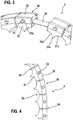
- the outer separator ring 3 comprises, as in particular from the FIGS. 3 and 4 each chain link 30 comprises a chain element 31, a closure element 32 and a pin 33. Further, the outer separation ring 3 comprises a circumferential steel band 34 to which the individual chain links 30 are attached. How out FIG. 3 it can be seen, a fastening of a chain link 30 on the steel strip 34 takes place in such a way that the steel strip 34 is arranged between the chain element 31 and the closure element 32. In this case, the closure element 32 is fastened by means of the pin 33 on the chain element 31. How out FIG. 4 it can be seen, the chain elements 31 are further constructed such that they provide a radially inner first stop 35 and a radially outer second stop 36.
- the flexibility of the outer separator ring 3 is limited.
- the pin 33 is fixed to the chain link 30 so as to have a protruding portion 33a projecting in the axial direction of the outer split ring 3.
- This projecting portion 33 a engages with a toothing 12, which is formed on the outer periphery of the receiving disk 18.
- a drive for the outer separating ring 3 is provided (cf. FIG. 5 ).
- the outer separator ring 3 has a simple structure, so that a low-wear, maintenance-free and inexpensive chain-shaped element is provided. In particular, this can be dispensed with a complex bolt connection for hingedly connected individual chain links.
- the flexibility of the outer separating ring 3 is ensured by the limited by the inner and outer stops 35, 36 mobility of the individual chain links 30 relative to adjacent chain links and the flexibility of the steel strip 34.
- a knife-like divider 31 a and a first trough quarter 31 b and a second trough portion 31 c is formed on the inner circumference of the outer separator ring 3 on the chain element 31.
- the two trough areas 31b and 31c form a first trough half 3a on the outer separating ring 3, each with adjacent trough quarters.
- a second trough half 2b is formed on the inner separating ring 2 (cf. FIG. 1 ), wherein the trough halves 2b are also separated from each other by knife-like dividers 2a.
- FIG. 1 it can be seen that the two separating rings 2, 3 are moved towards each other continuously until the separating web 2a of the inner separating ring 2 contacts the separating web 31a of the outer separating ring 3. At this moment, a mass piece of mass strand 4 is separated and formed in the trough formed between the inner and outer separator ring.
- a first die 9 and a second die 10 are moved toward each other in the axial direction to completely emboss the candy in the temporarily formed between the inner separator ring 2 and the outer separator ring 3 trough.
- the second die 10 is moved back again in the axial direction and the first die 9 is moved according to the cam track 13 in the direction of the second die 10 to the finished candy from the temporary trough between the two separating rings 2, 3 in the opening 8 in the receiving disk 18 to transfer.
- the rotational speed of the receiving disk 18 corresponds to that of the inner separating ring 2 and that of the outer separating ring 3.
- the outer separator ring 3 again moves away from the inner separator ring 2 as seen in FIG FIG. 1 is apparent.
- the candy 5 is finished during its stay in the trough between the two separating rings 2, 3.
- the device 1 according to the invention has the advantage that a separated only from the mass strand 4 mass piece quietly in the temporary trough between the two separating rings 2, 3 remains, so that a permanent closing and cooling of the separated part is possible and thus leakage of a liquid inner region 4a can be prevented.
- FIG. 1 is thus according to the invention thus the outer parting ring 3 for a long period of time directly on the inner parting ring 2, in particular touching the partitions 2a, 31a of the two separating rings.
- FIG. 2 indicated corresponds to this area in which the two separating rings 2, 3, approximately the fourth circumference of the inner separator ring second
- the present invention is particularly suitable for the preparation of candy-type confectionery, e.g. filled hard or soft caramel. Due to the continuous movement of the inner separating ring 2 and the outer separating ring 3, a high productivity of candies 5 produced from a supplied mass strand 4 can be ensured. A drive of the outer separator ring 3 via the teeth 12 and is thus integrated on the inner separator ring 2. Thereby, a structure of the device according to the invention can be further simplified.
Landscapes
- Engineering & Computer Science (AREA)
- Mechanical Engineering (AREA)
- Life Sciences & Earth Sciences (AREA)
- Chemical & Material Sciences (AREA)
- Food Science & Technology (AREA)
- Polymers & Plastics (AREA)
- General Engineering & Computer Science (AREA)
- Confectionery (AREA)
Description
- Die vorliegende Erfindung betrifft eine Vorrichtung zum Formen von aus einem Massenstrang gefertigten Waren, insbesondere bonbonartige Süßwaren.
- Eine derartige Vorrichtung ist aus der
DE 10 2005 018 077 A1 bekannt. Diese bekannte Vorrichtung zum Formen von Bonbons aus einem Massenstrang weist einen umlaufenden Prägekammerring mit parallel zu dessen Drehachse beidseitig offenen Prägekammern und mit zu den Prägekammern fluchtend zugeordneten Prägestempelpaaren auf, deren Stempel gegenläufig in die zugehörige Prägekammer verschiebbar sind. Seitlich des Prägekammerrings sind zwei zueinander exzentrisch umlaufende, sich aufeinander abwälzende Trennringe vorgesehen. Die Trennringe weisen messerartige Trennstege mit dazwischen angeordneten Halbformmulden auf. Die Trennstege dienen zum Abtrennen von Einzelstücken aus dem Massenstrang. Das Abtrennen erfolgt dabei bei einer Annäherung der beiden Trennringe während ihres Umlaufs, wobei der Massenstrang zwischen den beiden Trennringen zugeführt wird. Nach dem Abtrennen der Einzelstücke werden diese von den Formmulden aufgenommen und geformt. Beim weiteren Umlauf der Trennringe werden die vorgeformten Bonbons mittels der Prägestempel in die als Durchgangsbohrungen ausgebildeten Prägekammern des Prägekammerrings verschoben, wo das Prägen der Bonbons mittels der gegeneinander bewegten Prägestempel stattfindet. Anschließend werden die geprägten Bonbons mittels der Prägestempel auf eine Fördereinrichtung ausgeworfen. - Ein Nachteil der bekannten Vorrichtung liegt darin begründet, dass sich der äußere Trennring und der innere Trennring nur an einem Punkt, dem Abschneidepunkt der Bonbonmasse von dem Massenstrang, berühren. Direkt danach bewegen sich die Trennstege wieder voneinander weg. Dies führt jedoch dazu, dass das vom Massenstrang abgetrennte Massestück freigegeben wird und sich zwischen dem inneren Trennring und dem äußeren Trennring immer mehr bewegen kann, je weiter sich die beiden Trennringe voneinander entfernen. Im nächsten Schritt wird das noch ungeprägte Massestück mittels der Prägestempel nun in eine Prägekammer des Prägekammerrings verschoben. Dabei besteht die Gefahr, dass das abgetrennte Massestück an Kanten der Vorrichtung anstößt und sich öffnen kann. Insbesondere bei Süßigkeiten, welche in ihrem Inneren einen flüssigen Bestandteil aufweisen, besteht dabei die Gefahr, dass diese Flüssigkeit nach einem Stoß der abgetrennten Masse an eine Kante austritt. Ferner kann aufgrund der geringen Schließzeit einer Schnittkante der Masse auch keine Zeit gegeben werden, sich abzukühlen, so dass auch dadurch die Gefahr besteht, dass flüssige Innenbestandteile durch die noch nicht geschlossene Schnittkante austreten. Ferner kann von der äußeren Hülle des abgetrennten Massestücks während des Verschiebevorgangs auch ein erhöhter Grußabfall (Zuckerstaub) auftreten.
- Die erfindungsgemäße Vorrichtung zum Formen von aus einem Massenstrang gefertigten Waren, insbesondere bonbonartigen Süßwaren, gemäß Anspruch 1 weist demgegenüber den Vorteil auf, dass eine Beschädigung eines abgetrennten Massestücks vom Massenstrang vermieden werden kann. Ferner kann eine Verschlusszeit, in welcher sich ein abgetrenntes Massestück zwischen einem äußeren und einem inneren Trennring befindet, vergrößert werden, so dass eine Abkühlung und somit ein dauerhaftes Verschließen des abgetrennten Massestücks möglich ist. Ferner kann erfindungsgemäß das abgetrennte Massestück in der Position zwischen dem inneren und äußeren Trennring geprägt werden, so dass auf einen separaten Prägekammerring verzichtet werden kann. Dies wird erfindungsgemäß dadurch erreicht, dass der äußere Trennring flexibel ausgestaltet ist. Hierdurch kann eine längere Kontaktzeit zwischen dem äußeren Trennring und dem inneren Trennring realisiert werden und somit das Bonbon zwischen den beiden Trennringen fertiggeprägt werden. Da das Bonbon nach dem Abtrennen vom Massenstrang bis zum fertigen Prägen nicht mehr aus seiner Position gebracht werden muss, wird auch die Problematik von Beschädigungen des Bonbons und des Auftretens von Grußabfall o.Ä. vermieden. Dies wird dadurch erreicht, dass der äußere Trennring flexibel ist und nach dem Abtrennen eines Massestücks vom Massenstrang sich noch eine Weile mit dem inneren Trennring in Kontakt befindet. Dadurch kann das Prägen des abgetrennten Massestücks zum Bonbon in einer Position zwischen dem inneren und äußeren Trennring erfolgen. Nach dem Prägevorgang kann der äußere Trennring wieder vom inneren Trennring gelöst werden und die fertiggeprägte Ware kann abtransportiert werden.
- Aus der
DE 31 49 834 A1 ist eine Form zur Herstellung von harten und gefüllten, gestanzten Karamellen bekannt. Hierbei ist ein Rad vorgesehen, welches auf seinem äußeren Umfang eine Vielzahl von Verformungshalbsitzen aufweist. Diese arbeiten mit einem aus einer Vielzahl von als Kranzabschnitte ausgeführten Gleitstücken bestehenden äußeren Kranz zusammen, wobei die Gleitstücke am Rad beweglich in radialer Richtung gelagert sind. Die Gleitstücke sind jeweils durch ein Längsloch geführt, in dem eine Schraube durchgreift, die jeweils ein Gleitstück zwischen einem Stanzrad und einem Positionierungsring lagert. Das Öffnen der Gleitstücke erfolgt aufgrund der Fliehkraft während der Schließbewegung durch einen den Gleitstückkranz zu etwa drei Viertel des Umfangs umhüllenden Riemen. - Die Unteransprüche zeigen bevorzugte Weiterbildungen der Erfindung.
- Hierbei ist der äußere Trennring ein kettenartiges Element. Hierdurch kann auf einfache und kostengünstige Weise ein flexibler äußerer Trennring bereitgestellt werden.
- So umfasst das kettenartige Element eine Vielzahl von Kettengliedern, ein umlaufendes Band und eine Vielzahl von Verschlusselementen. Das umlaufende Band ist dabei zwischen den Kettengliedern und den Verschlusselementen angeordnet, wobei die Kettenglieder jeweils mittels der Verschlusselemente am umlaufenden Band befestigt sind. Die Kettenglieder können sich dabei relativ zum umlaufenden Band bewegen, um die Flexibilität des äußeren Trennrings bereitzustellen. Alternativ kann das kettenartige Element auch eine Vielzahl von Kettengliedern umfassen, welche mittels einer Bolzenverbindung miteinander gelenkig verbunden sind.
- Hierbei umfasst das kettenartige Element eine Vielzahl von Stiften, welche die Verschlusselemente jeweils an den Kettengliedern fixieren. Dadurch kann eine einfache Verbindung zwischen den Verschlusselementen und den Kettengliedern realisiert werden.
- Erfindungsgemäß stehen die Stifte seitlich über den äußeren Trennring vor, um mit einer Antriebseinrichtung zum Antreiben des äußeren Trennrings in Eingriff zu kommen.
- Die Unteransprüche zeigen bevorzugte Weiterbildungen der Erfindung. Besonders bevorzugt ist am inneren Trennring eine Verzahnung angeordnet, welche mit den vorstehenden Stiften am äußeren Trennring in Eingriff bringbar ist, um den äußeren Trennring anzutreiben.
- Gemäß einer weiteren bevorzugten Ausgestaltung der vorliegenden Erfindung ist das Band ein Stahlband. Hierdurch kann das kettenartige Element besonders kostengünstig bereitgestellt werden.
- Weiter bevorzugt umfasst ein Kettenglied einen messerartigen Trennsteg, ein erstes Muldenviertel und ein zweites Muldenviertel, wobei das erste Muldenviertel an einer ersten Seite des Trennstegs und das zweite Muldenviertel an einer zweiten Seite des Trennstegs angeordnet sind. Dabei wird eine Muldenhälfte des äußeren Trennrings durch zwei einander benachbarte Muldenviertel von zwei zueinander benachbarte Kettenglieder gebildet.
- Vorzugsweise weist jedes Kettenglied einen inneren Anschlag und einen äußeren Anschlag auf. Dadurch kann die Gelenkigkeit der einzelnen Kettenglieder auf ein vorbestimmtes Maß beschränkt werden.
- Gemäß einer weiteren bevorzugten Ausgestaltung der Erfindung ist seitlich benachbart zu den Trennringen ein Zwischenspeicher angeordnet, um fertiggeprägte Waren bis zu einer Auswerfereinheit zwischenzuspeichern. Hierdurch kann eine einfache Konstruktion der erfindungsgemäßen Vorrichtung ermöglicht werden und insbesondere ein beschädigungsfreier Übergang der fertiggeprägten Waren sichergestellt werden.
- Nachfolgend werden Ausführungsbeispiele der Erfindung unter Bezugnahme auf die begleitende Zeichnung im Detail beschrieben. In der Zeichnung ist:
- Figur 1
- eine schematische, teilweise geschnittene Seitenansicht einer Vorrichtung gemäß einem Ausführungsbeispiel der Erfindung,
- Figur 2
- eine schematische, perspektivische Ansicht der in
Figur 1 gezeigten Vorrichtung, - Figur 3
- eine schematische, perspektivische Ansicht eines in den
Figuren 1 und2 gezeigten flexiblen äußeren Trennrings, - Figur 4
- eine Seitenansicht des Trennring von
Figur 3 , und - Figur 5
- eine vergrößerte, perspektivische Teilansicht einer Verbindung zwischen dem äußeren Trennring und einem inneren Trennring.
- Nachfolgend wird unter Bezugnahme auf die
Figuren 1 bis 5 eine Vorrichtung 1 zum Formen von aus einem Massenstrang gefertigten Waren, insbesondere Bonbons, beschrieben. - In den Figuren ist eine Vorrichtung 1 dargestellt, welche zum Abtrennen und Prägen von Bonbons 5 aus einem ausgewalzten und ausgezogenen, insbesondere mit einem flüssigen oder halbflüssigen Füllgut 4a gefüllten Massenstrang 4 dient. Es sei jedoch angemerkt, dass anstelle der Bonbons auch jede andere Art von Süßwaren oder Kaugummistücken usw. hergestellt werden können.
- Wie insbesondere aus
Figur 1 ersichtlich ist, umfasst die Vorrichtung 1 einen inneren Trennring 2 und einen äußeren Trennring 3. Der äußere Trennring 3 ist dabei ein flexibler Ring, welcher in diesem Ausführungsbeispiel als kettenartiges Element vorgesehen ist. - Die Vorrichtung 1 umfasst ferner ein Förderband 6, welches an einer Umlenkrolle 7 umgelenkt wird und die fertiggeformten Bonbons 5 abführt (vgl.
Figur 1 ). - Wie aus
Figur 2 ersichtlich ist, umfasst die Vorrichtung 1 eine Vielzahl erster Prägestempel 9 und eine Vielzahl zweiter Prägestempel 10. Die ersten Prägestempel 9 sind dabei an einer ersten Seite der inneren und äußeren Trennringe 2, 3 angeordnet und die zweiten Prägestempel 10 sind dabei an der gegenüberliegenden Seite in Axialrichtung der inneren und äußeren Trennringe 2, 3 angeordnet. Die ersten Prägestempel 9 befinden sich mit einer Kurvenbahn 13 in Verbindung, welche eine axiale Position der ersten Prägestempel 9 vorgibt. In ähnlicher Weise sind die zweiten Prägestempel 10 mit einer Taumelscheibe 11 verbunden, welche ebenfalls die axiale Position der zweiten Prägestempel 10 vorgibt. Ferner ist an einer Seite in Axialrichtung der inneren und äußeren Trennringe 2, 3 eine Aufnahmescheibe 18 mit einer Vielzahl von Öffnungen 8 angeordnet. Wie ausFigur 2 ersichtlich ist, sind die Öffnungen 8 als Durchgangsöffnungen ausgebildet und weisen einen im Wesentlichen zylindrischen Querschnitt auf. Der Querschnitt der Öffnungen 8 entspricht dabei im Wesentlichen einem Querschnitt einer zwischen dem inneren Trennring 2 und dem äußeren Trennring 3 gebildeten Mulde. Ein mittlerer Durchmesser der Öffnungen 8 entspricht dabei einem mittleren Durchmesser der durch den inneren und äußeren Trennring 2, 3 gebildeten Mulden. - Wie insbesondere aus
Figur 5 ersichtlich ist, ist am äußeren Umfang der Aufnahmescheibe 18 ferner eine Verzahnung 12 vorgesehen. Die Verzahnung 12 kommt mit Zahnelementen, welche am äußeren Trennring 3 gebildet sind, in Eingriff und stellt somit den Antrieb für den äußeren Trennring 3 bereit. Die Zahnelemente sind, wie ausFigur 5 ersichtlich ist, vorstehende Bereiche 33a an Stiften 33. Über die Verzahnung 12 wird somit eine Rotationsgeschwindigkeit des inneren Trennrings 2 mit der des äußeren Trennrings 3 synchronisiert. - Der äußere Trennring 3 umfasst, wie insbesondere aus den
Figuren 3 und 4 ersichtlich ist, eine Vielzahl von Kettengliedern 30. Jedes Kettenglied 30 umfasst dabei ein Kettenelement 31, ein Verschlusselement 32 und einen Stift 33. Ferner umfasst der äußere Trennring 3 ein umlaufendes Stahlband 34, an welchem die einzelnen Kettenglieder 30 befestigt sind. Wie ausFigur 3 ersichtlich ist, erfolgt eine Befestigung eines Kettenglieds 30 am Stahlband 34 dabei derart, dass das Stahlband 34 zwischen dem Kettenelement 31 und dem Verschlusselement 32 angeordnet ist. Dabei wird das Verschlusselement 32 mittels des Stiftes 33 am Kettenelement 31 befestigt. Wie ausFigur 4 ersichtlich ist, sind die Kettenelemente 31 ferner derart aufgebaut, dass sie einen radial innenliegenden ersten Anschlag 35 und einen radial außenliegenden zweiten Anschlag 36 bereitstellen. Dadurch wird die Flexibilität des äußeren Trennrings 3 begrenzt. Wie aus denFiguren 3 und5 ersichtlich ist, ist der Stift 33 derart am Kettenglied 30 befestigt, dass er einen vorstehenden Bereich 33a aufweist, welcher in Axialrichtung des äußeren Trennrings 3 vorsteht. Dieser vorstehende Bereich 33a kommt mit einer Verzahnung 12 in Eingriff, welche am äußeren Umfang der Aufnahmescheibe 18 gebildet ist. Dadurch wird ein Antrieb für den äußeren Trennring 3 bereitgestellt (vgl.Figur 5 ). Somit weist der äußere Trennring 3 einen einfachen Aufbau auf, so dass ein verschleißarmes, wartungsfreies und kostengünstiges kettenförmiges Element bereitgestellt wird. Insbesondere kann dadurch auf eine aufwendige Bolzenverbindung für miteinander gelenkig verbundene einzelne Kettenglieder verzichtet werden. Die Gelenkigkeit des äußeren Trennrings 3 wird dabei durch die durch die inneren und äußeren Anschläge 35, 36 begrenzte Bewegbarkeit der einzelnen Kettenglieder 30 relativ zu benachbarten Kettengliedern sowie der Flexibilität des Stahlbandes 34 gewährleistet. - Wie ferner aus
Figur 3 ersichtlich ist, ist am inneren Umfang des äußeren Trennrings 3 am Kettenelement 31 ein messerartiger Trennsteg 31 a sowie ein erstes Muldenviertel 31b und ein zweites Muldenviertel 31c gebildet. Die beiden Muldenviertel 31b und 31c bilden dabei mit jeweils benachbarten Muldenvierteln eine erste Muldenhälfte 3a am äußeren Trennring 3. Eine zweite Muldenhälfte 2b ist am inneren Trennring 2 gebildet (vgl.Figur 1 ), wobei die Muldenhälften 2b ebenfalls jeweils durch messerartige Trennstege 2a voneinander getrennt sind. - Um nun aus dem zugeführten Massenstrang 4 einzelne Massestücke abzutrennen, werden, wie aus
Figur 1 ersichtlich ist, die beiden Trennringe 2, 3 kontinuierlich aufeinander zubewegt, bis der Trennsteg 2a des inneren Trennrings 2 den Trennsteg 31a des äußeren Trennrings 3 berührt. In diesem Moment wird ein Massestück vom Massenstrang 4 abgetrennt und in der zwischen dem inneren und äußeren Trennring gebildeten Mulde geformt. Um das Bonbon fertig zu formen, werden dann nach dem Abtrennen des Masseteils ein erster Prägestempel 9 und ein zweiter Prägestempel 10 in Axialrichtung aufeinander zubewegt, um das Bonbon in der temporär zwischen dem inneren Trennring 2 und dem äußeren Trennring 3 gebildeten Mulde fertig zu prägen. Nachdem das Bonbon 5 fertiggeprägt wurde, wird aufgrund der Vorgabe der Taumelscheibe 11 der zweite Prägestempel 10 wieder in Axialrichtung zurückbewegt und der erste Prägestempel 9 wird entsprechend der Kurvenbahn 13 weiter in Richtung des zweiten Prägestempels 10 bewegt, um das fertige Bonbon aus der temporären Mulde zwischen den beiden Trennringen 2, 3 in die Öffnung 8 in der Aufnahmescheibe 18 zu überführen. Dies ist problemlos möglich, da die Rotationsgeschwindigkeit der Aufnahmescheibe 18 der des inneren Trennrings 2 und der des äußeren Trennrings 3 entspricht. Anschließend wird, wie inFigur 2 angedeutet, das fertige Bonbon 5 aus der Öffnung 8 auf das Förderband 6 übergeben. Dies kann durch eine weitere entsprechende axiale Bewegung der Prägestempel erfolgen. Nach der Übergabe des fertigen Bonbons von der temporären Mulde zwischen dem inneren und äußeren Trennring entfernt sich der äußere Trennring 3 wieder vom inneren Trennring 2, wie ausFigur 1 ersichtlich ist. - Somit kann erfindungsgemäß sichergestellt werden, dass das Bonbon 5 noch während seines Aufenthalts in der Mulde zwischen den beiden Trennringen 2, 3 fertiggeprägt wird. Dadurch wird verhindert, dass einerseits Beschädigungen am Bonbon auftreten können und andererseits ein eventuell im Massenstrang 4 vorhandener flüssiger Innenbereich 4a aus dem noch nicht fertiggeprägten Bonbon auslaufen kann. Ferner hat die erfindungsgemäße Vorrichtung 1 den Vorteil, dass ein nur vom Massenstrang 4 abgetrenntes Massestück kurze Zeit ruhig in der temporären Mulde zwischen den beiden Trennringen 2, 3 verbleibt, so dass ein dauerhaftes Verschließen und Abkühlen des abgetrennten Teils möglich ist und somit ein Austreten eines flüssigen Innenbereichs 4a verhindert werden kann.
- Wie aus
Figur 1 ersichtlich ist, liegt erfindungsgemäß somit der äußere Trennring 3 über einen längeren Zeitraum unmittelbar am inneren Trennring 2 an, wobei sich insbesondere die Trennstege 2a, 31a der beiden Trennringe berühren. Wie inFigur 2 angedeutet, entspricht dieser Bereich, in welchem sich die beiden Trennringe 2, 3 berühren, ungefähr dem viertel Umfang des inneren Trennrings 2. - Die vorliegende Erfindung eignet sich insbesondere zur Herstellung von bonbonartigen Süßwaren, wie z.B. gefüllten Hart- oder Weichkaramellen. Durch die kontinuierliche Bewegung des inneren Trennrings 2 und des äußeren Trennrings 3 kann dabei eine hohe Produktivität von aus einem zugeführten Massenstrang 4 hergestellten Bonbons 5 sichergestellt werden. Ein Antrieb des äußeren Trennrings 3 erfolgt über die Verzahnung 12 und ist somit am inneren Trennring 2 integriert. Dadurch kann ein Aufbau der erfindungsgemäßen Vorrichtung weiter vereinfacht werden.
Claims (5)
- Vorrichtung zum Formen von aus einem Massenstrang (4) gefertigten Waren (5), insbesondere bonbonartigen Süßwaren, umfassend einen inneren Trennring (2) mit einer Vielzahl von Muldenhälften (2b) und einer Vielzahl von Trennstegen (2a), einen äußeren Trennring (3), mit einer Vielzahl von Muldenhälften (3a) und einer Vielzahl von Trennstegen (31a), wobei sich die Trennstege (2a, 31a) beim Umlauf der Trennringe (2, 3) annähern und sich schließlich berühren, um Massestücke vom Massenstrang (4) abzutrennen, Prägestempelpaare mit jeweils einem ersten Prägestempel (9) und einem zweiten Prägestempel (10), wobei der erste Prägestempel (9) an einer ersten Seite der Trennringe (2, 3) angeordnet ist und der zweite Prägestempel (10) an einer zweiten Seite gegenüber der ersten Seite der Trennringe (2, 3) angeordnet ist, und eine Kurvensteuereinrichtung (11, 13), um eine Position der Prägestempel (9, 10) in Axialrichtung relativ zu den Trennringen (2, 3) zu bestimmen, wobei der äußere Trennring (3) flexibel ist und den inneren Trennring (2) während einer Prägephase der Ware (5) berührt, um die Ware zwischen dem inneren Trennring (2) und dem äußeren Trennring (3) mittels der Prägestempel (9, 10) zu prägen, wobei der äußere Trennring (3) ein kettenartiges Element ist, wobei das kettenartige Element eine Vielzahl von Kettengliedern (30) und ein umlaufendes Band (34) umfasst, wobei jedes Kettenglied (30) ein Kettenelement (31) und ein mit dem Kettenelement (31) verbundenes Verschlusselement (32) umfasst, wobei das Band (34) zwischen dem Kettenelement (31) und dem Verschlusselement (32) angeordnet ist, wobei jedes Kettenglied (3) ferner einen Stift (33) umfasst, welcher die Verschlusselemente (33) an den Kettenelementen (31) befestigt, dadurch gekennzeichnet, dass die Stifte (33) einen vorstehenden Bereich (33a) aufweisen, welcher seitlich in Axialrichtung über den äußeren Trennring (3) vorsteht, um mit einer Antriebseinrichtung für einen Antrieb des äußeren Trennrings (3) in Eingriff zu kommen.
- Vorrichtung nach Anspruch 1, dadurch gekennzeichnet, dass die Antriebseinrichtung eine Verzahnung (12) am inneren Trennring (2) umfasst, welche mit den Stiften (33) des äußeren Trennrings (3) in Eingriff bringbar ist, um den äußeren Trennring (3) anzutreiben.
- Vorrichtung nach einem der Ansprüche 1 bis 2, dadurch gekennzeichnet, dass das Band (34) ein Stahlband ist.
- Vorrichtung nach einem der Ansprüche 1 bis 3, dadurch gekennzeichnet, dass jedes Kettenelement (31) einen Trennsteg (31 a), ein erstes Muldenviertel (31 b) und ein zweites Muldenviertel (31 c) umfasst, wobei der Trennsteg (31 a) zwischen dem ersten Muldenviertel (31b) und dem zweiten Muldenviertel (31c) angeordnet ist und wobei jedes Muldenviertel mit einem benachbarten Muldenviertel eines benachbarten Kettenelements eine Muldenhälfte (3a) am äußeren Trennring (3) bildet.
- Vorrichtung nach einem der Ansprüche 1 bis 4, dadurch gekennzeichnet, dass jedes Kettenglied (30) einen inneren Anschlag (35) und einen äußeren Anschlag (36) aufweist.
Applications Claiming Priority (2)
| Application Number | Priority Date | Filing Date | Title |
|---|---|---|---|
| DE102007012308A DE102007012308A1 (de) | 2007-03-14 | 2007-03-14 | Vorrichtung zum Formen von aus einem Massenstrang gefertigten Waren |
| PCT/EP2008/050842 WO2008110400A2 (de) | 2007-03-14 | 2008-01-25 | Vorrichtung zum formen von aus einem massenstrang gefertigten waren |
Publications (2)
| Publication Number | Publication Date |
|---|---|
| EP2134189A2 EP2134189A2 (de) | 2009-12-23 |
| EP2134189B1 true EP2134189B1 (de) | 2017-03-29 |
Family
ID=39427504
Family Applications (1)
| Application Number | Title | Priority Date | Filing Date |
|---|---|---|---|
| EP08708181.6A Not-in-force EP2134189B1 (de) | 2007-03-14 | 2008-01-25 | Vorrichtung zum formen von aus einem massenstrang gefertigten waren |
Country Status (6)
| Country | Link |
|---|---|
| EP (1) | EP2134189B1 (de) |
| CN (1) | CN101631471B (de) |
| BR (1) | BRPI0806850A2 (de) |
| DE (1) | DE102007012308A1 (de) |
| ES (1) | ES2629772T3 (de) |
| WO (1) | WO2008110400A2 (de) |
Families Citing this family (2)
| Publication number | Priority date | Publication date | Assignee | Title |
|---|---|---|---|---|
| CN110074239B (zh) * | 2019-06-12 | 2023-11-14 | 佛山市南海中洪机械设备厂 | 一种自动化糖果冲压机 |
| US12610963B2 (en) * | 2022-11-14 | 2026-04-28 | Schenck Process Llc | Confectionary demolding device and process |
Family Cites Families (13)
| Publication number | Priority date | Publication date | Assignee | Title |
|---|---|---|---|---|
| DE247340C (de) * | ||||
| DE242282C (de) * | ||||
| DE394995C (de) * | 1922-04-14 | 1924-05-13 | Fritz Gessner | Bonbonmaschine zur Formung des Zuckerstranges durch Stempel |
| DE418894C (de) * | 1923-09-15 | 1925-09-16 | Paul Kaiser | Maschine zur Herstellung von Bonbons aus einem Zuckermassestrang |
| DE835985C (de) * | 1949-04-08 | 1952-04-07 | Albert Anton Henkel | Bonbonpraegemaschine |
| US2695569A (en) * | 1950-07-28 | 1954-11-30 | Curtiss Candy Company | Apparatus for making looped-cord lollipops |
| DE1180234B (de) * | 1959-11-16 | 1964-10-22 | Carle & Montanari Spa | Bonbonpraegemaschine |
| DE2643855C2 (de) * | 1976-09-29 | 1983-03-31 | Robert Bosch Gmbh, 7000 Stuttgart | Vorrichtung zum Prägen von Bonbons |
| IT1138332B (it) * | 1981-05-07 | 1986-09-17 | Carle & Montanari Spa | Stampo per la produzione di caramelle dure e ripiene tranciate |
| US5022841A (en) * | 1989-11-30 | 1991-06-11 | Francesco Rizzi | Chain die assembly for making hard and stuffed sugar drops |
| DE19918740C1 (de) * | 1999-04-24 | 2000-12-14 | Haensel Otto Gmbh | Prägekette zur Herstellung von Bonbons |
| US20020123402A1 (en) * | 2001-03-05 | 2002-09-05 | Mott Philip J. | Compression type inverted tooth chain |
| DE102005018077A1 (de) | 2005-04-19 | 2006-10-26 | Robert Bosch Gmbh | Vorrichtung zum Formen von aus einem Massestrang gefertigten Waren |
-
2007
- 2007-03-14 DE DE102007012308A patent/DE102007012308A1/de not_active Withdrawn
-
2008
- 2008-01-25 CN CN200880008269.7A patent/CN101631471B/zh not_active Expired - Fee Related
- 2008-01-25 EP EP08708181.6A patent/EP2134189B1/de not_active Not-in-force
- 2008-01-25 WO PCT/EP2008/050842 patent/WO2008110400A2/de not_active Ceased
- 2008-01-25 BR BRPI0806850-0A patent/BRPI0806850A2/pt not_active IP Right Cessation
- 2008-01-25 ES ES08708181.6T patent/ES2629772T3/es active Active
Non-Patent Citations (1)
| Title |
|---|
| None * |
Also Published As
| Publication number | Publication date |
|---|---|
| CN101631471B (zh) | 2014-07-30 |
| CN101631471A (zh) | 2010-01-20 |
| DE102007012308A1 (de) | 2008-09-18 |
| WO2008110400A3 (de) | 2008-10-30 |
| ES2629772T3 (es) | 2017-08-14 |
| WO2008110400A2 (de) | 2008-09-18 |
| BRPI0806850A2 (pt) | 2014-04-29 |
| EP2134189A2 (de) | 2009-12-23 |
Similar Documents
| Publication | Publication Date | Title |
|---|---|---|
| DE60001843T2 (de) | Anlage zur kontinuielichen formung von gefülltem kaugummi | |
| DE69714675T2 (de) | Vorrichtung zum Schneiden und Formen eines kugelförmigen Körpers | |
| EP1245862B1 (de) | Antriebskette für ein Fahrrad oder dergleichen | |
| DE3025507A1 (de) | Verfahren und vorrichtung zum formen und verpacken von gegenstaenden aus einer weichen masse | |
| DE2643855A1 (de) | Verfahren und vorrichtung zum formen von bonbons o.dgl. aus einem massestrang | |
| DE2215506A1 (de) | Verriegelung- und Entreigelungsvorrichtung für Plattenelemente | |
| EP2982456A1 (de) | Vorrichtung und Verfahren zum Herstellen von für Synchronisationssysteme geeignete mit Zähnen bzw. Zahnabschnitten versehene Kupplungskörper | |
| DE2252423A1 (de) | Vorrichtung zum formen von lutschern | |
| DE102019001725A1 (de) | Werkzeug zum Spritzgießen von Kunststoff-Formteilen und Verfahren zum Bewegen eines Schiebers einer Werkzeughälfte des Werkzeugs | |
| DE19739515A1 (de) | Vorrichtung zum Schmieden eines Zahnkreises mit Schrägverzahnung | |
| EP2134189A2 (de) | Vorrichtung zum formen von aus einem massenstrang gefertigten waren | |
| EP3927483A1 (de) | EINTEILIGER SPEISERKÖRPER ZUR VERWENDUNG BEIM GIEßEN VON METALLEN | |
| WO1986003437A1 (fr) | Dispositif de presse pour la fabrication d'une cremaillere de direction | |
| EP1874529B1 (de) | Vorrichtung zum formen von aus einem massestrang gefertigten waren | |
| EP0691884B1 (de) | Vorrichtung zur herstellung von granulat | |
| DE102007010063B4 (de) | Prägekette zur Herstellung gratfreier geformter Artikel | |
| DE69202081T2 (de) | Kandis-Formmaschine. | |
| DE3149834C2 (de) | Vorrichtung zur Herstellung von harten und gefüllten, gestanzten Bonbons | |
| DE102005042758B3 (de) | Vorrichtung und Verfahren zur Herstellung eines Objektes mit Innengewinde | |
| DE102004059263B4 (de) | Vorrichtung zum Formen rotationssymmetrischer Körper aus einer modellierbaren, pastösen Masse | |
| EP1048221A2 (de) | Prägekette zur Herstellung von Bonbons | |
| EP0792736B1 (de) | Verfahren, spritzgegossene Laufrolle und Spritzgiessform zur Herstellung einer Laufrolle | |
| DE1180234B (de) | Bonbonpraegemaschine | |
| DE505152C (de) | Maschine zur Herstellung von Bonbons aus einem Massestrang | |
| AT410186B (de) | Einrichtung zum formen sphärischer gegenstände |
Legal Events
| Date | Code | Title | Description |
|---|---|---|---|
| PUAI | Public reference made under article 153(3) epc to a published international application that has entered the european phase |
Free format text: ORIGINAL CODE: 0009012 |
|
| 17P | Request for examination filed |
Effective date: 20091014 |
|
| AK | Designated contracting states |
Kind code of ref document: A2 Designated state(s): AT BE BG CH CY CZ DE DK EE ES FI FR GB GR HR HU IE IS IT LI LT LU LV MC MT NL NO PL PT RO SE SI SK TR |
|
| 17Q | First examination report despatched |
Effective date: 20100129 |
|
| DAX | Request for extension of the european patent (deleted) | ||
| REG | Reference to a national code |
Ref country code: DE Ref legal event code: R079 Ref document number: 502008015165 Country of ref document: DE Free format text: PREVIOUS MAIN CLASS: A23G0003020000 Ipc: B30B0011080000 |
|
| GRAP | Despatch of communication of intention to grant a patent |
Free format text: ORIGINAL CODE: EPIDOSNIGR1 |
|
| RIC1 | Information provided on ipc code assigned before grant |
Ipc: F16G 1/22 20060101ALI20161122BHEP Ipc: B30B 11/20 20060101ALI20161122BHEP Ipc: A23G 3/02 20060101ALI20161122BHEP Ipc: A23G 3/12 20060101ALI20161122BHEP Ipc: B30B 11/08 20060101AFI20161122BHEP |
|
| INTG | Intention to grant announced |
Effective date: 20161223 |
|
| GRAS | Grant fee paid |
Free format text: ORIGINAL CODE: EPIDOSNIGR3 |
|
| GRAA | (expected) grant |
Free format text: ORIGINAL CODE: 0009210 |
|
| AK | Designated contracting states |
Kind code of ref document: B1 Designated state(s): AT BE BG CH CY CZ DE DK EE ES FI FR GB GR HR HU IE IS IT LI LT LU LV MC MT NL NO PL PT RO SE SI SK TR |
|
| REG | Reference to a national code |
Ref country code: GB Ref legal event code: FG4D Free format text: NOT ENGLISH |
|
| REG | Reference to a national code |
Ref country code: CH Ref legal event code: EP |
|
| REG | Reference to a national code |
Ref country code: AT Ref legal event code: REF Ref document number: 879333 Country of ref document: AT Kind code of ref document: T Effective date: 20170415 |
|
| REG | Reference to a national code |
Ref country code: IE Ref legal event code: FG4D Free format text: LANGUAGE OF EP DOCUMENT: GERMAN |
|
| REG | Reference to a national code |
Ref country code: DE Ref legal event code: R096 Ref document number: 502008015165 Country of ref document: DE |
|
| PG25 | Lapsed in a contracting state [announced via postgrant information from national office to epo] |
Ref country code: FI Free format text: LAPSE BECAUSE OF FAILURE TO SUBMIT A TRANSLATION OF THE DESCRIPTION OR TO PAY THE FEE WITHIN THE PRESCRIBED TIME-LIMIT Effective date: 20170329 Ref country code: LT Free format text: LAPSE BECAUSE OF FAILURE TO SUBMIT A TRANSLATION OF THE DESCRIPTION OR TO PAY THE FEE WITHIN THE PRESCRIBED TIME-LIMIT Effective date: 20170329 Ref country code: NO Free format text: LAPSE BECAUSE OF FAILURE TO SUBMIT A TRANSLATION OF THE DESCRIPTION OR TO PAY THE FEE WITHIN THE PRESCRIBED TIME-LIMIT Effective date: 20170629 Ref country code: GR Free format text: LAPSE BECAUSE OF FAILURE TO SUBMIT A TRANSLATION OF THE DESCRIPTION OR TO PAY THE FEE WITHIN THE PRESCRIBED TIME-LIMIT Effective date: 20170630 Ref country code: HR Free format text: LAPSE BECAUSE OF FAILURE TO SUBMIT A TRANSLATION OF THE DESCRIPTION OR TO PAY THE FEE WITHIN THE PRESCRIBED TIME-LIMIT Effective date: 20170329 |
|
| REG | Reference to a national code |
Ref country code: NL Ref legal event code: MP Effective date: 20170329 |
|
| REG | Reference to a national code |
Ref country code: ES Ref legal event code: FG2A Ref document number: 2629772 Country of ref document: ES Kind code of ref document: T3 Effective date: 20170814 |
|
| PG25 | Lapsed in a contracting state [announced via postgrant information from national office to epo] |
Ref country code: SE Free format text: LAPSE BECAUSE OF FAILURE TO SUBMIT A TRANSLATION OF THE DESCRIPTION OR TO PAY THE FEE WITHIN THE PRESCRIBED TIME-LIMIT Effective date: 20170329 Ref country code: LV Free format text: LAPSE BECAUSE OF FAILURE TO SUBMIT A TRANSLATION OF THE DESCRIPTION OR TO PAY THE FEE WITHIN THE PRESCRIBED TIME-LIMIT Effective date: 20170329 Ref country code: BG Free format text: LAPSE BECAUSE OF FAILURE TO SUBMIT A TRANSLATION OF THE DESCRIPTION OR TO PAY THE FEE WITHIN THE PRESCRIBED TIME-LIMIT Effective date: 20170629 |
|
| PG25 | Lapsed in a contracting state [announced via postgrant information from national office to epo] |
Ref country code: NL Free format text: LAPSE BECAUSE OF FAILURE TO SUBMIT A TRANSLATION OF THE DESCRIPTION OR TO PAY THE FEE WITHIN THE PRESCRIBED TIME-LIMIT Effective date: 20170329 |
|
| PG25 | Lapsed in a contracting state [announced via postgrant information from national office to epo] |
Ref country code: EE Free format text: LAPSE BECAUSE OF FAILURE TO SUBMIT A TRANSLATION OF THE DESCRIPTION OR TO PAY THE FEE WITHIN THE PRESCRIBED TIME-LIMIT Effective date: 20170329 Ref country code: RO Free format text: LAPSE BECAUSE OF FAILURE TO SUBMIT A TRANSLATION OF THE DESCRIPTION OR TO PAY THE FEE WITHIN THE PRESCRIBED TIME-LIMIT Effective date: 20170329 Ref country code: SK Free format text: LAPSE BECAUSE OF FAILURE TO SUBMIT A TRANSLATION OF THE DESCRIPTION OR TO PAY THE FEE WITHIN THE PRESCRIBED TIME-LIMIT Effective date: 20170329 Ref country code: CZ Free format text: LAPSE BECAUSE OF FAILURE TO SUBMIT A TRANSLATION OF THE DESCRIPTION OR TO PAY THE FEE WITHIN THE PRESCRIBED TIME-LIMIT Effective date: 20170329 |
|
| PG25 | Lapsed in a contracting state [announced via postgrant information from national office to epo] |
Ref country code: IS Free format text: LAPSE BECAUSE OF FAILURE TO SUBMIT A TRANSLATION OF THE DESCRIPTION OR TO PAY THE FEE WITHIN THE PRESCRIBED TIME-LIMIT Effective date: 20170729 Ref country code: PT Free format text: LAPSE BECAUSE OF FAILURE TO SUBMIT A TRANSLATION OF THE DESCRIPTION OR TO PAY THE FEE WITHIN THE PRESCRIBED TIME-LIMIT Effective date: 20170731 Ref country code: PL Free format text: LAPSE BECAUSE OF FAILURE TO SUBMIT A TRANSLATION OF THE DESCRIPTION OR TO PAY THE FEE WITHIN THE PRESCRIBED TIME-LIMIT Effective date: 20170329 |
|
| REG | Reference to a national code |
Ref country code: DE Ref legal event code: R097 Ref document number: 502008015165 Country of ref document: DE |
|
| PG25 | Lapsed in a contracting state [announced via postgrant information from national office to epo] |
Ref country code: DK Free format text: LAPSE BECAUSE OF FAILURE TO SUBMIT A TRANSLATION OF THE DESCRIPTION OR TO PAY THE FEE WITHIN THE PRESCRIBED TIME-LIMIT Effective date: 20170329 |
|
| PLBE | No opposition filed within time limit |
Free format text: ORIGINAL CODE: 0009261 |
|
| STAA | Information on the status of an ep patent application or granted ep patent |
Free format text: STATUS: NO OPPOSITION FILED WITHIN TIME LIMIT |
|
| 26N | No opposition filed |
Effective date: 20180103 |
|
| PG25 | Lapsed in a contracting state [announced via postgrant information from national office to epo] |
Ref country code: SI Free format text: LAPSE BECAUSE OF FAILURE TO SUBMIT A TRANSLATION OF THE DESCRIPTION OR TO PAY THE FEE WITHIN THE PRESCRIBED TIME-LIMIT Effective date: 20170329 |
|
| REG | Reference to a national code |
Ref country code: CH Ref legal event code: PL |
|
| GBPC | Gb: european patent ceased through non-payment of renewal fee |
Effective date: 20180125 |
|
| PG25 | Lapsed in a contracting state [announced via postgrant information from national office to epo] |
Ref country code: MT Free format text: LAPSE BECAUSE OF FAILURE TO SUBMIT A TRANSLATION OF THE DESCRIPTION OR TO PAY THE FEE WITHIN THE PRESCRIBED TIME-LIMIT Effective date: 20170329 |
|
| PG25 | Lapsed in a contracting state [announced via postgrant information from national office to epo] |
Ref country code: LU Free format text: LAPSE BECAUSE OF NON-PAYMENT OF DUE FEES Effective date: 20180125 Ref country code: FR Free format text: LAPSE BECAUSE OF NON-PAYMENT OF DUE FEES Effective date: 20180131 |
|
| REG | Reference to a national code |
Ref country code: IE Ref legal event code: MM4A |
|
| REG | Reference to a national code |
Ref country code: FR Ref legal event code: ST Effective date: 20180928 |
|
| REG | Reference to a national code |
Ref country code: BE Ref legal event code: MM Effective date: 20180131 |
|
| PG25 | Lapsed in a contracting state [announced via postgrant information from national office to epo] |
Ref country code: LI Free format text: LAPSE BECAUSE OF NON-PAYMENT OF DUE FEES Effective date: 20180131 Ref country code: CH Free format text: LAPSE BECAUSE OF NON-PAYMENT OF DUE FEES Effective date: 20180131 Ref country code: BE Free format text: LAPSE BECAUSE OF NON-PAYMENT OF DUE FEES Effective date: 20180131 Ref country code: GB Free format text: LAPSE BECAUSE OF NON-PAYMENT OF DUE FEES Effective date: 20180125 |
|
| PG25 | Lapsed in a contracting state [announced via postgrant information from national office to epo] |
Ref country code: IE Free format text: LAPSE BECAUSE OF NON-PAYMENT OF DUE FEES Effective date: 20180125 |
|
| PG25 | Lapsed in a contracting state [announced via postgrant information from national office to epo] |
Ref country code: IT Free format text: LAPSE BECAUSE OF NON-PAYMENT OF DUE FEES Effective date: 20180125 |
|
| REG | Reference to a national code |
Ref country code: AT Ref legal event code: MM01 Ref document number: 879333 Country of ref document: AT Kind code of ref document: T Effective date: 20180125 |
|
| PG25 | Lapsed in a contracting state [announced via postgrant information from national office to epo] |
Ref country code: AT Free format text: LAPSE BECAUSE OF NON-PAYMENT OF DUE FEES Effective date: 20180125 |
|
| PG25 | Lapsed in a contracting state [announced via postgrant information from national office to epo] |
Ref country code: MC Free format text: LAPSE BECAUSE OF FAILURE TO SUBMIT A TRANSLATION OF THE DESCRIPTION OR TO PAY THE FEE WITHIN THE PRESCRIBED TIME-LIMIT Effective date: 20170329 |
|
| REG | Reference to a national code |
Ref country code: ES Ref legal event code: FD2A Effective date: 20190731 |
|
| PG25 | Lapsed in a contracting state [announced via postgrant information from national office to epo] |
Ref country code: ES Free format text: LAPSE BECAUSE OF NON-PAYMENT OF DUE FEES Effective date: 20180126 |
|
| PG25 | Lapsed in a contracting state [announced via postgrant information from national office to epo] |
Ref country code: TR Free format text: LAPSE BECAUSE OF FAILURE TO SUBMIT A TRANSLATION OF THE DESCRIPTION OR TO PAY THE FEE WITHIN THE PRESCRIBED TIME-LIMIT Effective date: 20170329 |
|
| REG | Reference to a national code |
Ref country code: DE Ref legal event code: R082 Ref document number: 502008015165 Country of ref document: DE Representative=s name: DAUB, THOMAS, DIPL.-ING., DE Ref country code: DE Ref legal event code: R081 Ref document number: 502008015165 Country of ref document: DE Owner name: SYNTEGON TECHNOLOGY GMBH, DE Free format text: FORMER OWNER: ROBERT BOSCH GMBH, 70469 STUTTGART, DE Ref country code: DE Ref legal event code: R081 Ref document number: 502008015165 Country of ref document: DE Owner name: HANSELLA GMBH, DE Free format text: FORMER OWNER: ROBERT BOSCH GMBH, 70469 STUTTGART, DE |
|
| PG25 | Lapsed in a contracting state [announced via postgrant information from national office to epo] |
Ref country code: HU Free format text: LAPSE BECAUSE OF FAILURE TO SUBMIT A TRANSLATION OF THE DESCRIPTION OR TO PAY THE FEE WITHIN THE PRESCRIBED TIME-LIMIT; INVALID AB INITIO Effective date: 20080125 |
|
| PG25 | Lapsed in a contracting state [announced via postgrant information from national office to epo] |
Ref country code: CY Free format text: LAPSE BECAUSE OF FAILURE TO SUBMIT A TRANSLATION OF THE DESCRIPTION OR TO PAY THE FEE WITHIN THE PRESCRIBED TIME-LIMIT Effective date: 20170329 |
|
| REG | Reference to a national code |
Ref country code: DE Ref legal event code: R081 Ref document number: 502008015165 Country of ref document: DE Owner name: HANSELLA GMBH, DE Free format text: FORMER OWNER: SYNTEGON TECHNOLOGY GMBH, 71332 WAIBLINGEN, DE |
|
| PGFP | Annual fee paid to national office [announced via postgrant information from national office to epo] |
Ref country code: DE Payment date: 20220119 Year of fee payment: 15 |
|
| REG | Reference to a national code |
Ref country code: DE Ref legal event code: R119 Ref document number: 502008015165 Country of ref document: DE |
|
| PG25 | Lapsed in a contracting state [announced via postgrant information from national office to epo] |
Ref country code: DE Free format text: LAPSE BECAUSE OF NON-PAYMENT OF DUE FEES Effective date: 20230801 |