EP2131064B1 - Kettenschubantrieb mit vermindertem Polygoneffekt - Google Patents
Kettenschubantrieb mit vermindertem Polygoneffekt Download PDFInfo
- Publication number
- EP2131064B1 EP2131064B1 EP08010153A EP08010153A EP2131064B1 EP 2131064 B1 EP2131064 B1 EP 2131064B1 EP 08010153 A EP08010153 A EP 08010153A EP 08010153 A EP08010153 A EP 08010153A EP 2131064 B1 EP2131064 B1 EP 2131064B1
- Authority
- EP
- European Patent Office
- Prior art keywords
- chain
- push
- sprocket
- pull
- actuator
- Prior art date
- Legal status (The legal status is an assumption and is not a legal conclusion. Google has not performed a legal analysis and makes no representation as to the accuracy of the status listed.)
- Active
Links
- 230000000694 effects Effects 0.000 title claims abstract description 31
- 230000003472 neutralizing effect Effects 0.000 claims description 4
- 230000007704 transition Effects 0.000 claims description 4
- 238000000034 method Methods 0.000 claims description 2
- 230000009467 reduction Effects 0.000 description 5
- 230000001788 irregular Effects 0.000 description 4
- 230000003319 supportive effect Effects 0.000 description 2
- 230000009471 action Effects 0.000 description 1
- 230000001771 impaired effect Effects 0.000 description 1
- 230000003993 interaction Effects 0.000 description 1
- 238000004519 manufacturing process Methods 0.000 description 1
- 230000007246 mechanism Effects 0.000 description 1
- 238000006386 neutralization reaction Methods 0.000 description 1
- 238000005096 rolling process Methods 0.000 description 1
- 238000007493 shaping process Methods 0.000 description 1
Images


Classifications
-
- F—MECHANICAL ENGINEERING; LIGHTING; HEATING; WEAPONS; BLASTING
- F16—ENGINEERING ELEMENTS AND UNITS; GENERAL MEASURES FOR PRODUCING AND MAINTAINING EFFECTIVE FUNCTIONING OF MACHINES OR INSTALLATIONS; THERMAL INSULATION IN GENERAL
- F16H—GEARING
- F16H19/00—Gearings comprising essentially only toothed gears or friction members and not capable of conveying indefinitely-continuing rotary motion
- F16H19/02—Gearings comprising essentially only toothed gears or friction members and not capable of conveying indefinitely-continuing rotary motion for interconverting rotary or oscillating motion and reciprocating motion
- F16H19/06—Gearings comprising essentially only toothed gears or friction members and not capable of conveying indefinitely-continuing rotary motion for interconverting rotary or oscillating motion and reciprocating motion comprising flexible members, e.g. an endless flexible member
- F16H19/0636—Gearings comprising essentially only toothed gears or friction members and not capable of conveying indefinitely-continuing rotary motion for interconverting rotary or oscillating motion and reciprocating motion comprising flexible members, e.g. an endless flexible member the flexible member being a non-buckling chain
-
- E—FIXED CONSTRUCTIONS
- E05—LOCKS; KEYS; WINDOW OR DOOR FITTINGS; SAFES
- E05F—DEVICES FOR MOVING WINGS INTO OPEN OR CLOSED POSITION; CHECKS FOR WINGS; WING FITTINGS NOT OTHERWISE PROVIDED FOR, CONCERNED WITH THE FUNCTIONING OF THE WING
- E05F11/00—Man-operated mechanisms for operating wings, including those which also operate the fastening
- E05F11/02—Man-operated mechanisms for operating wings, including those which also operate the fastening for wings in general, e.g. fanlights
- E05F11/04—Man-operated mechanisms for operating wings, including those which also operate the fastening for wings in general, e.g. fanlights with cords, chains or cables
- E05F11/06—Man-operated mechanisms for operating wings, including those which also operate the fastening for wings in general, e.g. fanlights with cords, chains or cables in guide-channels
-
- E—FIXED CONSTRUCTIONS
- E05—LOCKS; KEYS; WINDOW OR DOOR FITTINGS; SAFES
- E05F—DEVICES FOR MOVING WINGS INTO OPEN OR CLOSED POSITION; CHECKS FOR WINGS; WING FITTINGS NOT OTHERWISE PROVIDED FOR, CONCERNED WITH THE FUNCTIONING OF THE WING
- E05F15/00—Power-operated mechanisms for wings
- E05F15/60—Power-operated mechanisms for wings using electrical actuators
- E05F15/603—Power-operated mechanisms for wings using electrical actuators using rotary electromotors
- E05F15/611—Power-operated mechanisms for wings using electrical actuators using rotary electromotors for swinging wings
- E05F15/616—Power-operated mechanisms for wings using electrical actuators using rotary electromotors for swinging wings operated by push-pull mechanisms
- E05F15/619—Power-operated mechanisms for wings using electrical actuators using rotary electromotors for swinging wings operated by push-pull mechanisms using flexible or rigid rack-and-pinion arrangements
-
- F—MECHANICAL ENGINEERING; LIGHTING; HEATING; WEAPONS; BLASTING
- F16—ENGINEERING ELEMENTS AND UNITS; GENERAL MEASURES FOR PRODUCING AND MAINTAINING EFFECTIVE FUNCTIONING OF MACHINES OR INSTALLATIONS; THERMAL INSULATION IN GENERAL
- F16G—BELTS, CABLES, OR ROPES, PREDOMINANTLY USED FOR DRIVING PURPOSES; CHAINS; FITTINGS PREDOMINANTLY USED THEREFOR
- F16G13/00—Chains
- F16G13/18—Chains having special overall characteristics
- F16G13/20—Chains having special overall characteristics stiff; Push-pull chains
-
- E—FIXED CONSTRUCTIONS
- E05—LOCKS; KEYS; WINDOW OR DOOR FITTINGS; SAFES
- E05Y—INDEXING SCHEME ASSOCIATED WITH SUBCLASSES E05D AND E05F, RELATING TO CONSTRUCTION ELEMENTS, ELECTRIC CONTROL, POWER SUPPLY, POWER SIGNAL OR TRANSMISSION, USER INTERFACES, MOUNTING OR COUPLING, DETAILS, ACCESSORIES, AUXILIARY OPERATIONS NOT OTHERWISE PROVIDED FOR, APPLICATION THEREOF
- E05Y2201/00—Constructional elements; Accessories therefor
- E05Y2201/60—Suspension or transmission members; Accessories therefor
- E05Y2201/622—Suspension or transmission members elements
- E05Y2201/644—Flexible elongated pulling elements
- E05Y2201/656—Chains
-
- E—FIXED CONSTRUCTIONS
- E05—LOCKS; KEYS; WINDOW OR DOOR FITTINGS; SAFES
- E05Y—INDEXING SCHEME ASSOCIATED WITH SUBCLASSES E05D AND E05F, RELATING TO CONSTRUCTION ELEMENTS, ELECTRIC CONTROL, POWER SUPPLY, POWER SIGNAL OR TRANSMISSION, USER INTERFACES, MOUNTING OR COUPLING, DETAILS, ACCESSORIES, AUXILIARY OPERATIONS NOT OTHERWISE PROVIDED FOR, APPLICATION THEREOF
- E05Y2201/00—Constructional elements; Accessories therefor
- E05Y2201/60—Suspension or transmission members; Accessories therefor
- E05Y2201/622—Suspension or transmission members elements
- E05Y2201/71—Toothed gearing
- E05Y2201/722—Racks
- E05Y2201/724—Flexible
-
- E—FIXED CONSTRUCTIONS
- E05—LOCKS; KEYS; WINDOW OR DOOR FITTINGS; SAFES
- E05Y—INDEXING SCHEME ASSOCIATED WITH SUBCLASSES E05D AND E05F, RELATING TO CONSTRUCTION ELEMENTS, ELECTRIC CONTROL, POWER SUPPLY, POWER SIGNAL OR TRANSMISSION, USER INTERFACES, MOUNTING OR COUPLING, DETAILS, ACCESSORIES, AUXILIARY OPERATIONS NOT OTHERWISE PROVIDED FOR, APPLICATION THEREOF
- E05Y2900/00—Application of doors, windows, wings or fittings thereof
- E05Y2900/10—Application of doors, windows, wings or fittings thereof for buildings or parts thereof
- E05Y2900/13—Type of wing
- E05Y2900/148—Windows
-
- Y—GENERAL TAGGING OF NEW TECHNOLOGICAL DEVELOPMENTS; GENERAL TAGGING OF CROSS-SECTIONAL TECHNOLOGIES SPANNING OVER SEVERAL SECTIONS OF THE IPC; TECHNICAL SUBJECTS COVERED BY FORMER USPC CROSS-REFERENCE ART COLLECTIONS [XRACs] AND DIGESTS
- Y10—TECHNICAL SUBJECTS COVERED BY FORMER USPC
- Y10T—TECHNICAL SUBJECTS COVERED BY FORMER US CLASSIFICATION
- Y10T74/00—Machine element or mechanism
- Y10T74/18—Mechanical movements
- Y10T74/18568—Reciprocating or oscillating to or from alternating rotary
- Y10T74/1876—Reciprocating or oscillating to or from alternating rotary including inertia device
-
- Y—GENERAL TAGGING OF NEW TECHNOLOGICAL DEVELOPMENTS; GENERAL TAGGING OF CROSS-SECTIONAL TECHNOLOGIES SPANNING OVER SEVERAL SECTIONS OF THE IPC; TECHNICAL SUBJECTS COVERED BY FORMER USPC CROSS-REFERENCE ART COLLECTIONS [XRACs] AND DIGESTS
- Y10—TECHNICAL SUBJECTS COVERED BY FORMER USPC
- Y10T—TECHNICAL SUBJECTS COVERED BY FORMER US CLASSIFICATION
- Y10T74/00—Machine element or mechanism
- Y10T74/18—Mechanical movements
- Y10T74/18568—Reciprocating or oscillating to or from alternating rotary
- Y10T74/18832—Reciprocating or oscillating to or from alternating rotary including flexible drive connector [e.g., belt, chain, strand, etc.]
- Y10T74/1884—Reciprocating or oscillating to or from alternating rotary including flexible drive connector [e.g., belt, chain, strand, etc.] with sprocket wheel
-
- Y—GENERAL TAGGING OF NEW TECHNOLOGICAL DEVELOPMENTS; GENERAL TAGGING OF CROSS-SECTIONAL TECHNOLOGIES SPANNING OVER SEVERAL SECTIONS OF THE IPC; TECHNICAL SUBJECTS COVERED BY FORMER USPC CROSS-REFERENCE ART COLLECTIONS [XRACs] AND DIGESTS
- Y10—TECHNICAL SUBJECTS COVERED BY FORMER USPC
- Y10T—TECHNICAL SUBJECTS COVERED BY FORMER US CLASSIFICATION
- Y10T74/00—Machine element or mechanism
- Y10T74/18—Mechanical movements
- Y10T74/18568—Reciprocating or oscillating to or from alternating rotary
- Y10T74/18832—Reciprocating or oscillating to or from alternating rotary including flexible drive connector [e.g., belt, chain, strand, etc.]
- Y10T74/18848—Reciprocating or oscillating to or from alternating rotary including flexible drive connector [e.g., belt, chain, strand, etc.] with pulley
Definitions
- the present invention relates generally to actuators for push-pull chains, in particular to actuators with sprocket driven chains and guides for the push-pull chains used in these actuators.
- a push-pull chain can be extended and retracted by an actuator basically comprising a driving sprocket and a housing for the push-pull chain.
- the driving sprocket engages the push-pull chain's rollers and drives it in the desired direction.
- the sprocket is provided with as few teeth as possible.
- typically the sprocket has five teeth since the so called polygon effect becomes to large and disruptive for the actuator operation with fewer than five teeth.
- roller chain actuators there need to be provided with a chain exit guide that least supports two rollers at the time, otherwise the chain becomes instable.
- the links of the chain exit guide is a limiting factor in reducing the size of such actuators.
- Another problem is that as the push-pull chain is under push load, as e.g. in a push-pull chain being used to open a window, the push-pull chain is urged away from the sprocket due to the push force exerted on the push-pull chain by the load. This effect may cause the push-pull chain to disengage the sprocket completely or partly leading to noise and partially or completely impaired function.
- a first guide surface is used to guide the push-pull chain along the sprocket and prevents the push-pull chain from moving away from the sprocket and keeps the push-pull chain in close relation to the sprocket.
- Actuators having guide surfaces such as these still make a lot of noise and the push-pull chain is prone to rattle, in particular due to a swaying movement of the push-pull chain in the vicinity of the chain exit caused by the interaction of the sprocket with the push-pull chain.
- the push-pull chain As the push-pull chain progresses along the sprocket it will first come in contact with the sprocket, follow it and then leave it. Doing so the rollers 8b of the push-pull chain are being engaged by different parts of the sprocket, i.e. the teeth of and the recesses in-between them. As the recesses are closer to the centre of the sprocket than the teeth, the sprocket has a polygonal geometry, and when the sprocket is rotating with a steady speed the resulting chain velocity is varying. Also the force transmitted from the sprocket to the push-pull chain will be un-even in both direction and amplitude.
- EP 0 994 231 discloses a chain thrust drive comprising a motor, chain and housing with a chain exit, and exit guide which is movable about the axis of rotation of a chain sprocket for reducing the polygon effect caused by the sprocket.
- An actuator mechanism moves the exit guide in the movement positioning element.
- a rotating guiding part is formed as a hollow guiding housing for the chain shackle and a relatively stationary guiding part is a roller guide for the chain rollers.
- the push-pull chain By guiding the push-pull chain in a way that neutralizes or at least reduces the effects of the polygonal effect of the sprocket the push-pull chain can be made to leave the actuator at a steady speed and load, causing less wear and noise. Further, this measure had the unexpected side effect that the angle at which the chain leaves the actuator varies less when the chain is moving and thus, the actuator can be constructed with a build in chain exit/entry angle closer to 90°, resulting in a higher push load bearing capacity of the chain.
- the chain exit can be constructed shorter because the exit guide extends into the arc shaped guide that guides the chain around the sprocket.
- a shorter exit guide allows for a reduced width of the housing and therewith a slimmer actuator.
- the second chain guide part comprises a path for said rollers formed by a series of interconnected arc shaped sections.
- the geometrical centres of said arc shaped sections may are on the same side of the chain as the geometrical centre of the first chain guide part.
- the geometrical centres of said arc shaped sections maybe substantially arranged on a line extending parallel to the predetermined chain exit/entry direction.
- the line may coincide with the centre of the sprocket.
- the arc shaped sections in said series may have a radius that is substantially identical to the radius of the path defined by the first chain guide part.
- transition between said arc shaped sections is preferably rounded off or rendered smooth.
- An actuator having a guide surface such as any of the above described will have the benefits of using less power, making less engine noise and less rattling as the guide cam steadies the push-pull chain.
- An actuator such as described above can advantageously be used for a window system using a push-pull chain to open and close a window as this field has a high requirement for low noise levels, reliable operation, easy installing and low power consumption.
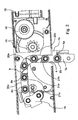
- a push-pull chain actuator 1 according to an embodiment of the invention is shown.
- the actuator has a housing 5 and is provided with a push-pull chain 3 and with an electric drive motor 15.
- the housing 1 is provided with the chain magazine 25, which is empty in figure 1 since the push-pull chain 3 is shown in its fully extended position.
- the push-pull 3 chain has not been drawn in its full length, but it is understood that the push-pull chain 3 can extend much further from the actuator 1 than shown in Fig. 1 .
- the actuator 1 has a sprocket 2 having a number of teeth 9(in this embodiment 5 teeth) and a chain exit opening 4 adjacent to the sprocket 2 through which the push-pull chain 3 can extend from the actuator 1.
- the actuator 1 has a housing 5 for receiving the push-pull chain 3.
- An electric drive motor 15 drives the sprocket 2 via a reduction gear that includes worm (which cannot be seen in this cross-section), a wormwheel 16 and further reduction gears 18 in an as such well known manner. According to another embodiment (not shown) the actuator is manually powered.
- the push-pull chain 3 includes a plurality of inner links 7a and outer links 7b that are connected by drive pins 8a around which the links 7 can move in relation to each other so that the push-pull chain 3 is at least partially flexible.
- the opposing inner links of a pair are connected by bushings 8c.
- the bushings 8c are provided with rollers 8b to minimize the friction caused while being engaged by the sprocket 2.
- the chain can freely bend from a configuration in a straight line in one direction- However, from the straight configuration the push-pull chain 3 can only bend to a limited extend in the opposite direction to provide the required stiffness for the push action in an as such well known manner.
- the "stiffness in the one direction is obtained in a well known manner through the shape of the inner and outer links 7a,7b, so that their ends abut when the chain 3 is bend in the "opposite" direction.
- Both sides of the chain 3 are open (as opposed to some types of push-pull chains that have a closed back) so that the rollers 8b are accessible for contact with guide surfaces on both sides of the push-pull chain 3.
- Fig. 2 the internal extremity 19 of the push-pull chain 3 is visible with the push-pull chain 3 being in its fully extended position.
- the sprocket 2 has a number of teeth 9. The higher the number of teeth 9 the smaller angular distance between them which leads to either a larger sprocket 2 or thinner teeth 9 and/or corresponding chain dimensions i.e. a weaker push-pull chain. To ensure a robust and load bearing structure the sprocket 2 should have as few teeth 9 as possible. However, a large angle between the teeth 9 worsens the so called polygon effect that results in an uneven chain speed and correspondingly uneven load, both being undesirable effects. A sprocket 2 with less than four teeth 9 leads to a very uneven operation as the angular distance between the teeth get so large that the polygon effect gets very prone. With more than 5 to 6 teeth the sprocket becomes bigger and the push-pull chain 3 thinner and thereby weaker if the same dimensions for the housing are to be kept.
- the push-pull chain 3 As the push-pull chain 3 is driven by the sprocket 2 it undertakes first a substantially linear motion that is changed into a semi-circular or angular motion around the sprocket 2 and finally another substantially linear motion as it extends from the actuator 1. Due to this the actuator 1 can be installed along narrow ledges, window sills and the like as the push-pull chain 3 does not extend linearly all the way, i.e. to the back of the actuator and away from a ledge or the like.
- FIGS. 1 and 3 illustrate a chain guide of the actuator of figures 1 in greater detail.
- the chain guide ensures that the push pull chain 3 follows the correct path of movement between the chain magazine 25 and the chain exit/entry opening 4.
- the chain guide is provided with guide surfaces on which the rollers 8b run when the push-pull chain 3 moves through the chain guide.
- the push-pull chain 3 is guided by contact between the rollers 8b and the guide surfaces of the chain guide.
- a first chain guide part 10a ensures that the push-pull chain 3 follows an arc shaped path around a portion of the sprocket 2 so that the sprocket 2 can engage the rollers 8b and transmit the load of the push-pull chain 3 to the sprocket 2.
- This load can be the weight or inertia of a window (not shown) that is being opened, closed or maintained in an open position by the push-pull chain 3 using the actuator 1.
- the first chain guide part 10a includes a radially outer arc shaped guide surface 20a that serves to guide the chain links 7a, 7b around the sprocket 2 and a radially inner guide surface 21a that will need to provide no or little guiding since the guiding of the chain in the radially inner direction will be provided by the sprocket 2.
- the guide surface 20a is arranged on a first guide cam 11 and the guide surface 21a is provided on a second guide cam 13.
- the first guide cam 11 and the second guide cam 13 form together the chain guide.
- the first chain guide part 10a extends between interrupted lines Q and W for approximately 90°.
- the first chain guide part 10a is arranged to be in contact with the rollers 8b of the chain and to keep the rollers 8b close to the sprocket 2 and thereby guide the push-pull chain 3 around the sprocket 2 also when the push-pull chain 3 is under push load.
- a second chain guide part 10b serves to guide the push-pull chain 3 between the sprocket 2 and the chain exit/entry opening 4, and in particular to ensure the correct exit/entry direction of the chain to provide the required stability against push loads.
- the second chain guide part 10b is provided with two opposite guide surfaces: a first exit/entry guide surface 20b that is formed on the first guide cam 11 and a second exit/entry guide surface 21b that is formed on the second guide cam 13.
- the second chain guide part 10b extends between interrupted line X the chain exit/entry opening 4 ( figure 5 ).
- the second chain guide part 10b defines a meandering path for the chain. The resulting meandering movement of the rollers 8b that can be best seen in Figs 4 to 6 the chain 3 counteracts or at least reduces the polygon effect.
- the details of the second chain guide portion 10b will be described in greater detail further below.
- a third chain guide part 10c serves to guide the chain between the chain magazine and the first chain guide part 10a.
- the third chain guide part 10c is provided with opposing guide surfaces 20c and 21c for ensuring that the chain travels correctly between the sprocket 2 and the chain magazine.
- the actuator is designed so that the push-pull chain 3 extends at an angle that slightly exceeds a straight angle from the actuator 1 so that the push-pull chain 3 is urged into its stable orientation. This desired or correct angle is indicated in figures 4a and 4b.
- the irregular shape of the chain in combination with the polygon effect causes in conventional actuators with a non-meandering exit guide (the part of the chain guide that corresponds to the second chain guide part) fluctuations of the actual chain angle from the design angle.
- a non-meandering exit guide the part of the chain guide that corresponds to the second chain guide part
- the chain angle variations in the conventional chain guides is typically ⁇ 2° from the angle with which the exit guide is constructed. Since the chain angle should under no circumstances become less than 90°, the conventional actuators have typically been constructed with an angle of 93° or more so that the will not lead to fluctuations that cause the actual chain angle to fall below 91°.
- the meandering path on the second chain guide part (also called chain exit guide) 10b annihilates or at least greatly reduces the fluctuations of the angle of the push pull chain 3 leaving the actuator 1 completely or at least substantially and therefore the chain that according to the present invention can be constructed with an inbuilt angle as low as 91,5°.
- the fluctuation of the chain angle with the meandering exit guide or second chain guide part 10b is only ⁇ 0,5°, i.e. the chain changes between 91° and 92° with an inbuilt chain angle of 91,5°.
- the building chain angle can with meandering chain path according to the invention be kept closer to 90° which means that the chain support higher push loads. Further, the reduction in swaying movement of the push pull chain 3 will reduce the amount of noise and rattling calls by the actuator 1.
- the reduction or neutralization of the polygon effect further reduces the amount of noise produced by the actuator 1 in operation since the movement of the chain angle of the object to be moved will be smooth and without fluctuations.
- the second chain guide part 10b can be meandering undulating, lobed, have protrusions, consist of curved portions or deviate from a straight line or a constant radius curve in various ways.
- the second chain guide part 10b or exit/entry guide needs guide surfaces on both sides of the chain/rollers.
- the mathematically optimal form for completely neutralizing the polygon effect is by shaping the second chain guide part 10b as a series of interconnected arc sections, the arc sections having a radius that is equal to the radius of the first chain guide part 10a and the arc sections hang an angular extend equal to the angle between the teeth of the sprocket.
- the "first" arc section at the sprocket extends halfway into the "conventional" substantially 90° arc section that forms the first chain guide part 10a.
- the first arc section of the second part of the chain guide 10b is only 36°, this is because the arc around the sprocket 2 cannot be extended further than 36° over the interrupted line marked X.
- the next arc sections are in the embodiment of Fig. 33 each 72° and have a radius identical to the radius of the first chain guide part 10a. Also the first 36° arc section has a radius that is substantially identical to the radius of the first chain guide part 10a.
- the geometrical centres of said arc shaped sections of the second chain guide part 10b are on the same side of the chain 3 as the geometrical centre of the first chain guide part 10a.
- the geometrical centres of said arc shaped sections are substantially arranged on a line (indicated by the interrupted line marked Y) extending parallel to the predetermined chain exit/entry direction.
- the line marked Y coincides with the centre of the sprocket 2.
- the chain guide shown in figure 3 is constructed in accordance with the mathematically optimal way to fully neutralize the public and effect.
- the sharp transitions between the arc sections, at the guide surfaces 20b and 21b prevent smooth rolling of the rollers 8b, and in practical embodiments the sharp transitions will be rounded off.
- the second chain guide part 10b needs to extend for a length that ensures that at least two rollers 8b are supported at any time by the second chain guide part 10b (is this is also nicely illustrated in figures 4 to 106 ).
- This requirement is fulfilled with two arc sections of 72° for an actuator with a five tooth sprocket.
- the reduction of length of the chain exit guide 10b can be explained as follows. It is noted that the first arc shaped section of the exit guide 10b extends halfway (for 36° with arcs that are 72°) into the first chain guide part 10a, and thus the exit guide actually starts already at the interrupted line indicated W.
- the chain exit guide is partially wrapped around the sprocket and is drawn closer to the sprocket resulting in the exit opening being located closer to the sprocket and the width of the actuator being reduced when compared to an actuator with a conventional chain exit guide.
- An actuator with a reduced width is advantageous since such an actuator can be constructed slimmer and therefore easier to mount into a window frame or the like
- guide surfaces can be subdivided into smaller surfaces working together to steady the push-pull chain 3 or combined into one longer guiding surface that renders it easier to install them
- the guide surfaces 20a,20b,20c,21a,21b,21c can be designed to either only abut a joints or rollers 8b under and/or over a sprocket tooth 9 or have a slit through which the sprocket tooth 9 can pass depending on the length of the sprocket tooth 9 in relation to the width of the drive pin 8a.
- This also makes it possible to arrange the second guide cam 13 on top of and under the sprocket 2 and use it as a supportive member for the sprocket 2.
- both guide cams 11 and 13 the second and third guiding surfaces 10b and 12a are lobed or undulating or having curved portions to counteract the polygon properties of the sprocket 2 interacting with the chain links 7 B.
- actuator as described above can also be used beneficially for actuators that are manually operated.
Landscapes
- Engineering & Computer Science (AREA)
- General Engineering & Computer Science (AREA)
- Mechanical Engineering (AREA)
- Devices For Conveying Motion By Means Of Endless Flexible Members (AREA)
- Transmission Devices (AREA)
- Transmissions By Endless Flexible Members (AREA)
- Dry Shavers And Clippers (AREA)
- Lock And Its Accessories (AREA)
- Soil Working Implements (AREA)
- Ladders (AREA)
- Presses And Accessory Devices Thereof (AREA)
- Valve Device For Special Equipments (AREA)
- Vehicle Body Suspensions (AREA)
- Fuel-Injection Apparatus (AREA)
Claims (7)
- Kettenführung für einen Druck-Zugkettenaktuator (1), die Kettenführung umfassend ein erstes bogenförmiges Kettenführungsteil (10a) zum Führen des Abschnitts der Druck-Zugkette (3) um das Kettenrad (2) durch die Rollen (8b) der Kette unter Führung mittels der ersten bogenförmigen Kettenführung, ein zweites Kettenführungsteil (10b) zum Führen der Druck-Zugkette (3) in einer vorgegebenen Austritts-/Eintrittsrichtung zwischen dem Kettenrad (2) und der Kettenaustrittsöffnung (4) durch die Rollen (8b) der Kette unter Führung mittels der zweiten Kettenführung, wobei die Kettenführung zum Neutralisieren oder zumindest Reduzieren des Polygoneffekts des Kettenrads (2) auf die Druck-Zugkette (3) durch das zweite Kettenführungsteil (10b) geformt und bemessen ist, dadurch gekennzeichnet, dass das zweite Kettenführungsteil (10b) einen Weg für die Rollen (8b) umfasst, der durch eine Reihe miteinander verbundener, bogenförmiger Teilabschnitte ausgebildet ist, und wobei die geometrischen Mitten der bogenförmigen Teilabschnitte auf derselben Seite der Kette (3) wie die geometrische Mitte des ersten Kettenführungsteils (10a) sind.
- Kettenführung nach Anspruch 1, wobei die geometrischen Mitten der bogenförmigen Teilabschnitte (10c) im Wesentlichen auf einer Linie Y angeordnet sind, die parallel zu der vorgegebenen Kettenaustritts-/- eintrittsrichtung verläuft.
- Kettenführung nach Anspruch 1, wobei die bogenförmigen Teilabschnitte in der Reihe einen Radius aufweisen, der im Wesentlichen identisch mit dem Radius des Wegs ist, der durch das erste Kettenführungsteil (10a) definiert ist.
- Kettenführung nach einem der Ansprüche 1 bis 3, wobei der Übergang zwischen den bogenförmigen Teilabschnitten abgerundet oder ausgeglättet ausgeführt ist.
- Druck-Zugkettenaktuator (1) umfassend:ein Gehäuse (5) mit einer Kettenaustritts-/- eintrittsöffnung (4),eine Druck-Zugrollenkette (3),ein Kettenrad (2), das zur Ineingriffnahme der Rollen (8b) der Druck-Zugkette (3) angeordnet ist, wobei ein Abschnitt der Kette um das Kettenrad (2) geführt ist, wobei das Kettenrad beim Betrieb einen Polygoneffekt bewirkt, undeine Kettenführung nach einem der Ansprüche 1 bis 4.
- Aktuator nach Anspruch 5, wobei die Linie (Y) mit der Mitte des Kettenrads (2) zusammentrifft.
- Verfahren zum Neutralisieren oder zumindest Reduzieren des Polygoneffekts eines Kettenrads auf eine Druck-Zugkette (3) mit Rollen (8b) in einem Kettenaktuator (1), umfassend:Vorsehen einer Kettenführung zum Führen der Kette (3) um das Kettenrad (2) des Aktuators (1) und zwischen dem Kettenrad (2) und einer Kettenaustritts-/- eintrittsöffnung (4) durch Vorsehen einer Kettenführung, die einen Weg für die Druck-Zugkette (3) zwischen dem Kettenrad und der Kettenaustritts-/- eintrittsöffnung (4) definiert, der den Polygoneffekt durch Umfassen eines Wegs für die Rollen (8b) neutralisiert oder zumindest reduziert, dadurch gekennzeichnet, dass der Weg durch eine Reihe miteinander verbundener, bogenförmiger Teilabschnitte ausgebildet ist, und wobei die geometrischen Mitten der bogenförmigen Teilabschnitte auf derselben Seite der Kette (3) wie die geometrische Mitte des ersten Kettenführungsteils (10a) sind.
Priority Applications (9)
| Application Number | Priority Date | Filing Date | Title |
|---|---|---|---|
| EP08010153A EP2131064B1 (de) | 2008-06-04 | 2008-06-04 | Kettenschubantrieb mit vermindertem Polygoneffekt |
| DK08010153.8T DK2131064T3 (da) | 2008-06-04 | 2008-06-04 | Tryk-træk kædeoperator med reduceret polygoneffekt |
| AT08010153T ATE519044T1 (de) | 2008-06-04 | 2008-06-04 | Kettenschubantrieb mit vermindertem polygoneffekt |
| PCT/DK2009/000128 WO2010000260A1 (en) | 2008-06-04 | 2009-06-03 | Push-pull chain actuator with reduced chain vibrations |
| DK09772030.4T DK2297481T3 (da) | 2008-06-04 | 2009-06-03 | Tryk-træk kædeaktuator med reducerede kædevibrationer |
| US12/995,921 US8763482B2 (en) | 2008-06-04 | 2009-06-03 | Push-pull chain actuator with reduced chain vibrations |
| CN2009801211134A CN102057182B (zh) | 2008-06-04 | 2009-06-03 | 具有减小的链条振动的推拉式链条致动器 |
| EP09772030A EP2297481B1 (de) | 2008-06-04 | 2009-06-03 | Druck-zug-kettenaktuator mit verminderten kettenschwingungen |
| US14/075,793 US9476488B2 (en) | 2008-06-04 | 2013-11-08 | Push-pull chain actuator with reduced chain vibrations |
Applications Claiming Priority (1)
| Application Number | Priority Date | Filing Date | Title |
|---|---|---|---|
| EP08010153A EP2131064B1 (de) | 2008-06-04 | 2008-06-04 | Kettenschubantrieb mit vermindertem Polygoneffekt |
Publications (2)
| Publication Number | Publication Date |
|---|---|
| EP2131064A1 EP2131064A1 (de) | 2009-12-09 |
| EP2131064B1 true EP2131064B1 (de) | 2011-08-03 |
Family
ID=40010987
Family Applications (2)
| Application Number | Title | Priority Date | Filing Date |
|---|---|---|---|
| EP08010153A Active EP2131064B1 (de) | 2008-06-04 | 2008-06-04 | Kettenschubantrieb mit vermindertem Polygoneffekt |
| EP09772030A Active EP2297481B1 (de) | 2008-06-04 | 2009-06-03 | Druck-zug-kettenaktuator mit verminderten kettenschwingungen |
Family Applications After (1)
| Application Number | Title | Priority Date | Filing Date |
|---|---|---|---|
| EP09772030A Active EP2297481B1 (de) | 2008-06-04 | 2009-06-03 | Druck-zug-kettenaktuator mit verminderten kettenschwingungen |
Country Status (6)
| Country | Link |
|---|---|
| US (2) | US8763482B2 (de) |
| EP (2) | EP2131064B1 (de) |
| CN (1) | CN102057182B (de) |
| AT (1) | ATE519044T1 (de) |
| DK (2) | DK2131064T3 (de) |
| WO (1) | WO2010000260A1 (de) |
Families Citing this family (11)
| Publication number | Priority date | Publication date | Assignee | Title |
|---|---|---|---|---|
| ATE519044T1 (de) * | 2008-06-04 | 2011-08-15 | Vkr Holding As | Kettenschubantrieb mit vermindertem polygoneffekt |
| US20110308338A1 (en) * | 2010-06-22 | 2011-12-22 | Schluckebier Floyd A | Force transfer assembly |
| DE102011107047B4 (de) * | 2011-07-11 | 2019-12-12 | Iwis Antriebssysteme Gmbh & Co. Kg | Rückensteifer Kettenantrieb mit gleichmäßigem, stoßfreiem Kettenlauf |
| US20130202437A1 (en) * | 2012-02-08 | 2013-08-08 | Clipper Windpower, Llc | Roller Push Belt for Wind Turbine Drive Train Applications |
| DE102012113082A1 (de) * | 2012-12-24 | 2014-06-26 | Tsubaki Kabelschlepp GmbH | Energieführungsvorrichtung mit wenigstens einer Antriebseinrichtung für lange Verfahrwege |
| US10704314B2 (en) * | 2015-04-14 | 2020-07-07 | Wilmar Valverde | Automatic safety window apparatus and system |
| CN108350986A (zh) * | 2015-09-11 | 2018-07-31 | 生活机器人学股份有限公司 | 直动伸缩机构 |
| DE102016000568A1 (de) * | 2016-01-20 | 2017-07-20 | Iwis Antriebssysteme Gmbh & Co. Kg | Aktuator mit einer rückensteifen Kette |
| FR3061753B1 (fr) * | 2017-01-10 | 2019-05-31 | Serapid - France | Dispositif de chaine de poussee |
| DE102018203892A1 (de) * | 2018-03-14 | 2019-09-19 | Geze Gmbh | Kettenantrieb |
| KR20210049313A (ko) | 2019-10-25 | 2021-05-06 | 엘지디스플레이 주식회사 | 표시 장치 |
Family Cites Families (28)
| Publication number | Priority date | Publication date | Assignee | Title |
|---|---|---|---|---|
| US2044158A (en) * | 1934-04-12 | 1936-06-16 | Westinghouse Elec Elevator Co | Chain gear |
| US3217553A (en) * | 1962-05-10 | 1965-11-16 | Ct D Etudes Et D Applic Des Te | Transmission device |
| US4498890A (en) * | 1982-12-20 | 1985-02-12 | General Electric Company | Fixed track chain drive |
| US4521993A (en) * | 1983-08-08 | 1985-06-11 | Truth Incorporated | Chain operator for a window |
| US4827668A (en) | 1987-11-24 | 1989-05-09 | Bechtold Stephen K | Chain operator for a window |
| US5203746A (en) * | 1991-06-19 | 1993-04-20 | The Will-Burt Company | Telescoping mast assembly |
| US5358384A (en) * | 1993-05-03 | 1994-10-25 | Dysarz Edward D | Device and method to relieve cordelle action in a chain driven pump |
| DE4437250A1 (de) * | 1994-10-18 | 1996-04-25 | Heinrich Schlueter | Einrichtung für die Ausführung des Schließ- und Öffnungsvorganges eines Kippfensters |
| JP3451385B2 (ja) * | 1995-06-30 | 2003-09-29 | 鬼頭工業株式会社 | チェーンプッシャ装置 |
| DE29706739U1 (de) * | 1997-04-15 | 1997-06-12 | Grasl Andreas Ing | Einrichtung zur Übertragung einer Kraft, insbesondere Druckkraft, längs einer im wesentlichen geraden Strecke |
| US5895880A (en) * | 1997-10-14 | 1999-04-20 | Western Design Howden | Zipper chain projectile rammer |
| DE19831975A1 (de) * | 1997-12-05 | 1999-06-10 | Heidelberger Druckmasch Ag | Förderkette für einen ein Greifersystem tragenden Kettenförderer einer Druckmaschine |
| DE19924996A1 (de) * | 1998-06-26 | 1999-12-30 | Heidelberger Druckmasch Ag | Kettenförderer für eine Bogen verarbeitende Druckmaschine |
| DE29818339U1 (de) * | 1998-10-14 | 2000-02-24 | Aumueller Aumatic Gmbh | Kettenschubantrieb |
| ES2208471T3 (es) | 2001-01-26 | 2004-06-16 | Univ.-Prof. Dipl.-Ing. Dr. Techn. Jorg Oser O. | Transmision de cadena provista de una rueda poligonal de cadena. |
| US6890278B2 (en) * | 2001-02-14 | 2005-05-10 | Jeffrey Theorin Prince | Chain with selectivity engaged links |
| DE10138462B4 (de) * | 2001-08-04 | 2004-09-30 | Kone Corp. | Verfahren zum Führen von Laschenketten im Bereich von Umlenkeinrichtungen einer Personenförderanlage |
| JP2004231318A (ja) * | 2003-01-28 | 2004-08-19 | Tsubakimoto Chain Co | 搬送チェーン用ガイド |
| JP2004232667A (ja) * | 2003-01-28 | 2004-08-19 | Tsubakimoto Chain Co | 高速伝動用乗り継ぎガイド |
| JP4304136B2 (ja) * | 2004-03-23 | 2009-07-29 | 東芝エレベータ株式会社 | コンベア装置 |
| JP4454660B2 (ja) * | 2004-05-12 | 2010-04-21 | ヴィーケーアール・ホールディング・アー・エス | プッシュプルチェーンおよびアクチュエータ |
| CN2837608Y (zh) * | 2004-05-12 | 2006-11-15 | Vkr控股公司 | 推拉链以及致动器 |
| US7674199B2 (en) * | 2005-06-24 | 2010-03-09 | Meggitt Defense Systems, Inc. | Rigidizable chain |
| EP1801453A1 (de) * | 2005-12-22 | 2007-06-27 | Theodorus Henricus Johannes Carolina Korse | Kettentrieb |
| DE202006017304U1 (de) * | 2006-11-10 | 2007-01-11 | D + H Mechatronic Ag | Führung für eine rückensteife Kette |
| US8011260B2 (en) * | 2007-02-20 | 2011-09-06 | Teleflex Canada Inc. | Double chain linear actuator |
| ATE519044T1 (de) * | 2008-06-04 | 2011-08-15 | Vkr Holding As | Kettenschubantrieb mit vermindertem polygoneffekt |
| US20110308338A1 (en) * | 2010-06-22 | 2011-12-22 | Schluckebier Floyd A | Force transfer assembly |
-
2008
- 2008-06-04 AT AT08010153T patent/ATE519044T1/de active
- 2008-06-04 DK DK08010153.8T patent/DK2131064T3/da active
- 2008-06-04 EP EP08010153A patent/EP2131064B1/de active Active
-
2009
- 2009-06-03 US US12/995,921 patent/US8763482B2/en active Active
- 2009-06-03 CN CN2009801211134A patent/CN102057182B/zh active Active
- 2009-06-03 DK DK09772030.4T patent/DK2297481T3/da active
- 2009-06-03 EP EP09772030A patent/EP2297481B1/de active Active
- 2009-06-03 WO PCT/DK2009/000128 patent/WO2010000260A1/en active Application Filing
-
2013
- 2013-11-08 US US14/075,793 patent/US9476488B2/en active Active
Also Published As
| Publication number | Publication date |
|---|---|
| EP2297481A4 (de) | 2011-11-30 |
| DK2297481T3 (da) | 2013-04-15 |
| EP2297481A1 (de) | 2011-03-23 |
| EP2131064A1 (de) | 2009-12-09 |
| EP2297481B1 (de) | 2013-01-09 |
| US20110154923A1 (en) | 2011-06-30 |
| WO2010000260A8 (en) | 2010-12-16 |
| CN102057182B (zh) | 2013-04-17 |
| DK2131064T3 (da) | 2011-10-24 |
| ATE519044T1 (de) | 2011-08-15 |
| US8763482B2 (en) | 2014-07-01 |
| WO2010000260A1 (en) | 2010-01-07 |
| CN102057182A (zh) | 2011-05-11 |
| US20140060226A1 (en) | 2014-03-06 |
| US9476488B2 (en) | 2016-10-25 |
Similar Documents
| Publication | Publication Date | Title |
|---|---|---|
| EP2131064B1 (de) | Kettenschubantrieb mit vermindertem Polygoneffekt | |
| EP1747386B1 (de) | Zug-druck-kette und stellglied | |
| RU2378474C1 (ru) | Быстроходные промышленные жалюзийные ворота | |
| EP2503087B1 (de) | Türaufhängungsvorrichtung und türvorrichtung damit | |
| US8617014B2 (en) | Drive means and chain drive with polygonal compensation | |
| EP2146033B1 (de) | Zug- und Druckkette sowie Stellvorrichtung | |
| KR20070053206A (ko) | 액츄에이터 | |
| JP2015152172A (ja) | 開口部、特に機械開口部用カバー装置 | |
| JP4685429B2 (ja) | チェーン用のスプロケット | |
| US7500928B2 (en) | Randomized chain system | |
| JP2005530100A (ja) | 鎖伝動及びチェーン | |
| JP2007162349A (ja) | 車両用ガラス移動装置 | |
| JP3118237U (ja) | ウインドレギュレータ用インナーケーブル中継装置 | |
| KR100572661B1 (ko) | 스핀들 부재 제조방법, 이를 수행하는 스핀들 부재 제조장치 및 이에 사용되는 길다란 체인 | |
| CN110234908B (zh) | 推力链装置 | |
| JP6393065B2 (ja) | ウィンドレギュレータ装置 | |
| EP2123937B1 (de) | Gelenkkettenantrieb | |
| WO2015156355A1 (ja) | ウィンドレギュレータ装置 | |
| JP2012158893A (ja) | ロールスクリーン | |
| JP2015200148A (ja) | ウィンドレギュレータ装置 | |
| EP2687466B1 (de) | Förderband-Festziehvorrichtung | |
| JP6348323B2 (ja) | ウィンドレギュレータ装置 | |
| JP2015200151A (ja) | ウィンドレギュレータ装置 | |
| JP4454990B2 (ja) | 乗客コンベヤーの移動手摺装置 | |
| RU2327915C2 (ru) | Устройство для преобразования вращательного движения в поступательное |
Legal Events
| Date | Code | Title | Description |
|---|---|---|---|
| PUAI | Public reference made under article 153(3) epc to a published international application that has entered the european phase |
Free format text: ORIGINAL CODE: 0009012 |
|
| AK | Designated contracting states |
Kind code of ref document: A1 Designated state(s): AT BE BG CH CY CZ DE DK EE ES FI FR GB GR HR HU IE IS IT LI LT LU LV MC MT NL NO PL PT RO SE SI SK TR |
|
| AX | Request for extension of the european patent |
Extension state: AL BA MK RS |
|
| 17P | Request for examination filed |
Effective date: 20100319 |
|
| 17Q | First examination report despatched |
Effective date: 20100512 |
|
| AKX | Designation fees paid |
Designated state(s): AT BE BG CH CY CZ DE DK EE ES FI FR GB GR HR HU IE IS IT LI LT LU LV MC MT NL NO PL PT RO SE SI SK TR |
|
| GRAP | Despatch of communication of intention to grant a patent |
Free format text: ORIGINAL CODE: EPIDOSNIGR1 |
|
| GRAS | Grant fee paid |
Free format text: ORIGINAL CODE: EPIDOSNIGR3 |
|
| GRAA | (expected) grant |
Free format text: ORIGINAL CODE: 0009210 |
|
| RIN1 | Information on inventor provided before grant (corrected) |
Inventor name: OLE, FEJER Inventor name: SORENSEN, JENS JORREN |
|
| RIN1 | Information on inventor provided before grant (corrected) |
Inventor name: OLE, FEJER Inventor name: SORENSEN, JENS JORREN |
|
| AK | Designated contracting states |
Kind code of ref document: B1 Designated state(s): AT BE BG CH CY CZ DE DK EE ES FI FR GB GR HR HU IE IS IT LI LT LU LV MC MT NL NO PL PT RO SE SI SK TR |
|
| REG | Reference to a national code |
Ref country code: GB Ref legal event code: FG4D |
|
| REG | Reference to a national code |
Ref country code: CH Ref legal event code: EP |
|
| REG | Reference to a national code |
Ref country code: IE Ref legal event code: FG4D |
|
| REG | Reference to a national code |
Ref country code: DE Ref legal event code: R096 Ref document number: 602008008534 Country of ref document: DE Effective date: 20110929 |
|
| REG | Reference to a national code |
Ref country code: NL Ref legal event code: T3 |
|
| REG | Reference to a national code |
Ref country code: DK Ref legal event code: T3 |
|
| REG | Reference to a national code |
Ref country code: SE Ref legal event code: TRGR |
|
| LTIE | Lt: invalidation of european patent or patent extension |
Effective date: 20110803 |
|
| PG25 | Lapsed in a contracting state [announced via postgrant information from national office to epo] |
Ref country code: HR Free format text: LAPSE BECAUSE OF FAILURE TO SUBMIT A TRANSLATION OF THE DESCRIPTION OR TO PAY THE FEE WITHIN THE PRESCRIBED TIME-LIMIT Effective date: 20110803 Ref country code: LT Free format text: LAPSE BECAUSE OF FAILURE TO SUBMIT A TRANSLATION OF THE DESCRIPTION OR TO PAY THE FEE WITHIN THE PRESCRIBED TIME-LIMIT Effective date: 20110803 Ref country code: PT Free format text: LAPSE BECAUSE OF FAILURE TO SUBMIT A TRANSLATION OF THE DESCRIPTION OR TO PAY THE FEE WITHIN THE PRESCRIBED TIME-LIMIT Effective date: 20111205 Ref country code: IS Free format text: LAPSE BECAUSE OF FAILURE TO SUBMIT A TRANSLATION OF THE DESCRIPTION OR TO PAY THE FEE WITHIN THE PRESCRIBED TIME-LIMIT Effective date: 20111203 Ref country code: NO Free format text: LAPSE BECAUSE OF FAILURE TO SUBMIT A TRANSLATION OF THE DESCRIPTION OR TO PAY THE FEE WITHIN THE PRESCRIBED TIME-LIMIT Effective date: 20111103 Ref country code: FI Free format text: LAPSE BECAUSE OF FAILURE TO SUBMIT A TRANSLATION OF THE DESCRIPTION OR TO PAY THE FEE WITHIN THE PRESCRIBED TIME-LIMIT Effective date: 20110803 |
|
| PG25 | Lapsed in a contracting state [announced via postgrant information from national office to epo] |
Ref country code: LV Free format text: LAPSE BECAUSE OF FAILURE TO SUBMIT A TRANSLATION OF THE DESCRIPTION OR TO PAY THE FEE WITHIN THE PRESCRIBED TIME-LIMIT Effective date: 20110803 Ref country code: GR Free format text: LAPSE BECAUSE OF FAILURE TO SUBMIT A TRANSLATION OF THE DESCRIPTION OR TO PAY THE FEE WITHIN THE PRESCRIBED TIME-LIMIT Effective date: 20111104 Ref country code: SI Free format text: LAPSE BECAUSE OF FAILURE TO SUBMIT A TRANSLATION OF THE DESCRIPTION OR TO PAY THE FEE WITHIN THE PRESCRIBED TIME-LIMIT Effective date: 20110803 Ref country code: PL Free format text: LAPSE BECAUSE OF FAILURE TO SUBMIT A TRANSLATION OF THE DESCRIPTION OR TO PAY THE FEE WITHIN THE PRESCRIBED TIME-LIMIT Effective date: 20110803 Ref country code: CY Free format text: LAPSE BECAUSE OF FAILURE TO SUBMIT A TRANSLATION OF THE DESCRIPTION OR TO PAY THE FEE WITHIN THE PRESCRIBED TIME-LIMIT Effective date: 20110803 |
|
| PG25 | Lapsed in a contracting state [announced via postgrant information from national office to epo] |
Ref country code: BE Free format text: LAPSE BECAUSE OF FAILURE TO SUBMIT A TRANSLATION OF THE DESCRIPTION OR TO PAY THE FEE WITHIN THE PRESCRIBED TIME-LIMIT Effective date: 20110803 |
|
| PG25 | Lapsed in a contracting state [announced via postgrant information from national office to epo] |
Ref country code: CZ Free format text: LAPSE BECAUSE OF FAILURE TO SUBMIT A TRANSLATION OF THE DESCRIPTION OR TO PAY THE FEE WITHIN THE PRESCRIBED TIME-LIMIT Effective date: 20110803 Ref country code: SK Free format text: LAPSE BECAUSE OF FAILURE TO SUBMIT A TRANSLATION OF THE DESCRIPTION OR TO PAY THE FEE WITHIN THE PRESCRIBED TIME-LIMIT Effective date: 20110803 |
|
| PG25 | Lapsed in a contracting state [announced via postgrant information from national office to epo] |
Ref country code: EE Free format text: LAPSE BECAUSE OF FAILURE TO SUBMIT A TRANSLATION OF THE DESCRIPTION OR TO PAY THE FEE WITHIN THE PRESCRIBED TIME-LIMIT Effective date: 20110803 Ref country code: RO Free format text: LAPSE BECAUSE OF FAILURE TO SUBMIT A TRANSLATION OF THE DESCRIPTION OR TO PAY THE FEE WITHIN THE PRESCRIBED TIME-LIMIT Effective date: 20110803 |
|
| PLBE | No opposition filed within time limit |
Free format text: ORIGINAL CODE: 0009261 |
|
| STAA | Information on the status of an ep patent application or granted ep patent |
Free format text: STATUS: NO OPPOSITION FILED WITHIN TIME LIMIT |
|
| 26N | No opposition filed |
Effective date: 20120504 |
|
| REG | Reference to a national code |
Ref country code: DE Ref legal event code: R097 Ref document number: 602008008534 Country of ref document: DE Effective date: 20120504 |
|
| PG25 | Lapsed in a contracting state [announced via postgrant information from national office to epo] |
Ref country code: MC Free format text: LAPSE BECAUSE OF NON-PAYMENT OF DUE FEES Effective date: 20120630 |
|
| REG | Reference to a national code |
Ref country code: IE Ref legal event code: MM4A |
|
| PG25 | Lapsed in a contracting state [announced via postgrant information from national office to epo] |
Ref country code: IE Free format text: LAPSE BECAUSE OF NON-PAYMENT OF DUE FEES Effective date: 20120604 Ref country code: ES Free format text: LAPSE BECAUSE OF FAILURE TO SUBMIT A TRANSLATION OF THE DESCRIPTION OR TO PAY THE FEE WITHIN THE PRESCRIBED TIME-LIMIT Effective date: 20111114 |
|
| PG25 | Lapsed in a contracting state [announced via postgrant information from national office to epo] |
Ref country code: BG Free format text: LAPSE BECAUSE OF FAILURE TO SUBMIT A TRANSLATION OF THE DESCRIPTION OR TO PAY THE FEE WITHIN THE PRESCRIBED TIME-LIMIT Effective date: 20111103 |
|
| PG25 | Lapsed in a contracting state [announced via postgrant information from national office to epo] |
Ref country code: MT Free format text: LAPSE BECAUSE OF FAILURE TO SUBMIT A TRANSLATION OF THE DESCRIPTION OR TO PAY THE FEE WITHIN THE PRESCRIBED TIME-LIMIT Effective date: 20110803 |
|
| PG25 | Lapsed in a contracting state [announced via postgrant information from national office to epo] |
Ref country code: TR Free format text: LAPSE BECAUSE OF FAILURE TO SUBMIT A TRANSLATION OF THE DESCRIPTION OR TO PAY THE FEE WITHIN THE PRESCRIBED TIME-LIMIT Effective date: 20110803 |
|
| PG25 | Lapsed in a contracting state [announced via postgrant information from national office to epo] |
Ref country code: LU Free format text: LAPSE BECAUSE OF NON-PAYMENT OF DUE FEES Effective date: 20120604 |
|
| PG25 | Lapsed in a contracting state [announced via postgrant information from national office to epo] |
Ref country code: HU Free format text: LAPSE BECAUSE OF FAILURE TO SUBMIT A TRANSLATION OF THE DESCRIPTION OR TO PAY THE FEE WITHIN THE PRESCRIBED TIME-LIMIT Effective date: 20080604 |
|
| PGFP | Annual fee paid to national office [announced via postgrant information from national office to epo] |
Ref country code: CH Payment date: 20140612 Year of fee payment: 7 Ref country code: AT Payment date: 20140528 Year of fee payment: 7 Ref country code: SE Payment date: 20140611 Year of fee payment: 7 |
|
| PGFP | Annual fee paid to national office [announced via postgrant information from national office to epo] |
Ref country code: NL Payment date: 20140610 Year of fee payment: 7 |
|
| REG | Reference to a national code |
Ref country code: FR Ref legal event code: PLFP Year of fee payment: 8 |
|
| REG | Reference to a national code |
Ref country code: DE Ref legal event code: R081 Ref document number: 602008008534 Country of ref document: DE Owner name: WINDOWMASTER A/S, DK Free format text: FORMER OWNER: VKR HOLDING A/S, 2970 HORSHOLM, DK |
|
| REG | Reference to a national code |
Ref country code: GB Ref legal event code: 732E Free format text: REGISTERED BETWEEN 20150709 AND 20150715 |
|
| REG | Reference to a national code |
Ref country code: FR Ref legal event code: TP Owner name: WINDOWMASTER A/S, DK Effective date: 20150925 |
|
| REG | Reference to a national code |
Ref country code: CH Ref legal event code: PL |
|
| REG | Reference to a national code |
Ref country code: SE Ref legal event code: EUG |
|
| REG | Reference to a national code |
Ref country code: AT Ref legal event code: MM01 Ref document number: 519044 Country of ref document: AT Kind code of ref document: T Effective date: 20150604 |
|
| PG25 | Lapsed in a contracting state [announced via postgrant information from national office to epo] |
Ref country code: SE Free format text: LAPSE BECAUSE OF NON-PAYMENT OF DUE FEES Effective date: 20150605 |
|
| REG | Reference to a national code |
Ref country code: NL Ref legal event code: MM Effective date: 20150701 |
|
| PG25 | Lapsed in a contracting state [announced via postgrant information from national office to epo] |
Ref country code: NL Free format text: LAPSE BECAUSE OF NON-PAYMENT OF DUE FEES Effective date: 20150701 Ref country code: LI Free format text: LAPSE BECAUSE OF NON-PAYMENT OF DUE FEES Effective date: 20150630 Ref country code: CH Free format text: LAPSE BECAUSE OF NON-PAYMENT OF DUE FEES Effective date: 20150630 |
|
| PG25 | Lapsed in a contracting state [announced via postgrant information from national office to epo] |
Ref country code: AT Free format text: LAPSE BECAUSE OF NON-PAYMENT OF DUE FEES Effective date: 20150604 |
|
| REG | Reference to a national code |
Ref country code: FR Ref legal event code: PLFP Year of fee payment: 9 |
|
| REG | Reference to a national code |
Ref country code: FR Ref legal event code: PLFP Year of fee payment: 10 |
|
| REG | Reference to a national code |
Ref country code: FR Ref legal event code: PLFP Year of fee payment: 11 |
|
| P01 | Opt-out of the competence of the unified patent court (upc) registered |
Effective date: 20230516 |
|
| PGFP | Annual fee paid to national office [announced via postgrant information from national office to epo] |
Ref country code: FR Payment date: 20230626 Year of fee payment: 16 Ref country code: DK Payment date: 20230628 Year of fee payment: 16 Ref country code: DE Payment date: 20230626 Year of fee payment: 16 |
|
| PGFP | Annual fee paid to national office [announced via postgrant information from national office to epo] |
Ref country code: IT Payment date: 20230620 Year of fee payment: 16 Ref country code: GB Payment date: 20230627 Year of fee payment: 16 |