EP2129151A1 - Dispositif station de base et procédé de commande d'une communication - Google Patents
Dispositif station de base et procédé de commande d'une communication Download PDFInfo
- Publication number
- EP2129151A1 EP2129151A1 EP08711992A EP08711992A EP2129151A1 EP 2129151 A1 EP2129151 A1 EP 2129151A1 EP 08711992 A EP08711992 A EP 08711992A EP 08711992 A EP08711992 A EP 08711992A EP 2129151 A1 EP2129151 A1 EP 2129151A1
- Authority
- EP
- European Patent Office
- Prior art keywords
- user equipment
- equipment terminal
- allocated
- rbs
- base station
- Prior art date
- Legal status (The legal status is an assumption and is not a legal conclusion. Google has not performed a legal analysis and makes no representation as to the accuracy of the status listed.)
- Withdrawn
Links
Images


Classifications
-
- H—ELECTRICITY
- H04—ELECTRIC COMMUNICATION TECHNIQUE
- H04W—WIRELESS COMMUNICATION NETWORKS
- H04W72/00—Local resource management
- H04W72/12—Wireless traffic scheduling
- H04W72/1263—Mapping of traffic onto schedule, e.g. scheduled allocation or multiplexing of flows
- H04W72/1268—Mapping of traffic onto schedule, e.g. scheduled allocation or multiplexing of flows of uplink data flows
-
- H—ELECTRICITY
- H04—ELECTRIC COMMUNICATION TECHNIQUE
- H04W—WIRELESS COMMUNICATION NETWORKS
- H04W72/00—Local resource management
- H04W72/04—Wireless resource allocation
- H04W72/044—Wireless resource allocation based on the type of the allocated resource
- H04W72/0453—Resources in frequency domain, e.g. a carrier in FDMA
-
- H—ELECTRICITY
- H04—ELECTRIC COMMUNICATION TECHNIQUE
- H04B—TRANSMISSION
- H04B17/00—Monitoring; Testing
- H04B17/30—Monitoring; Testing of propagation channels
- H04B17/309—Measuring or estimating channel quality parameters
-
- H—ELECTRICITY
- H04—ELECTRIC COMMUNICATION TECHNIQUE
- H04L—TRANSMISSION OF DIGITAL INFORMATION, e.g. TELEGRAPHIC COMMUNICATION
- H04L1/00—Arrangements for detecting or preventing errors in the information received
- H04L1/0001—Systems modifying transmission characteristics according to link quality, e.g. power backoff
- H04L1/0002—Systems modifying transmission characteristics according to link quality, e.g. power backoff by adapting the transmission rate
- H04L1/0003—Systems modifying transmission characteristics according to link quality, e.g. power backoff by adapting the transmission rate by switching between different modulation schemes
-
- H—ELECTRICITY
- H04—ELECTRIC COMMUNICATION TECHNIQUE
- H04W—WIRELESS COMMUNICATION NETWORKS
- H04W52/00—Power management, e.g. TPC [Transmission Power Control], power saving or power classes
- H04W52/04—TPC
- H04W52/30—TPC using constraints in the total amount of available transmission power
- H04W52/36—TPC using constraints in the total amount of available transmission power with a discrete range or set of values, e.g. step size, ramping or offsets
- H04W52/365—Power headroom reporting
-
- H—ELECTRICITY
- H04—ELECTRIC COMMUNICATION TECHNIQUE
- H04W—WIRELESS COMMUNICATION NETWORKS
- H04W88/00—Devices specially adapted for wireless communication networks, e.g. terminals, base stations or access point devices
- H04W88/08—Access point devices
Definitions
- the present invention generally relates to a mobile communication system employing an Orthogonal Frequency Division Multiplexing (OFDM) scheme, and more particularly to a base station apparatus and a communication control method.
- OFDM Orthogonal Frequency Division Multiplexing
- an LTE system As a next-generation system of the W-CDMA (Wideband Code Division Multiple Access) and the HSDPA (High Speed Downlink Packet Access), an LTE system has been studied by 3GPP (3 rd Generation Partnership Project) which is a standards body of the W-CDMA.
- 3GPP 3 rd Generation Partnership Project
- an OFDM (Orthogonal Frequency Division Multiplexing) scheme and an SC-FDMA (Single-Carrier Frequency Division Multiple Access) scheme have been studied to be applied to the downlink communication system and the uplink communication system, respectively (see, 3GPP TR 25.814 (V7.0.0), "Physical Layer Aspects for Evolved UTRA", June 2006 , for example).
- a frequency band is divided into plural sub-carriers having narrower frequency bands, and data are transmitted on each sub frequency band (sub-carrier) and the sub-carriers are closely arranged so as not to interfere with each other, so that fast data transmission can be achieved and an efficiency use of the frequency band can be improved.
- a frequency band is divided in a manner so that different frequencies can be separately used among plural terminals (user equipment terminals) and as a result, interference between terminals can be reduced. Further, in the SC-FDMA scheme, a range of transmission power fluctuation can be made smaller; therefore lower energy consumption of terminals can be achieved and a wider coverage area can be obtained.
- the LTE system is a communication system using shared channels in both downlink and uplink.
- a base station apparatus selects a user equipment terminal to communicate using the shared channel in each sub-frame (each 1 ms) and instructs, using the downlink control channel, the selected user equipment terminal to communicate using the shared channel in a predetermined sub-frame.
- the user equipment terminal transmits the shared channel based on the downlink control channel.
- the base station apparatus receives and decodes the shared channel transmitted from the user equipment terminal. In this case, a process of selecting the user equipment terminal to communicate using the shared channel as described above is called a scheduling process.
- the transmission format includes various information items indicating such as allocation information about resource blocks (frequency resources), a modulation scheme, a payload size, information about transmission power, HARQ (Hybrid Automatic Repeat reQuest) information (a Redundancy version parameter, a process number, etc.), and MIMO (Multiple Input Multiple Output) information (a reference signal sequence for MIMO transmission, etc.).
- the transmission format of the shared channel and identification information of the user equipment terminal which communicates using the shared channel in the corresponding sub-frame are collectively called an Uplink Scheduling Grant.
- the transmission format of the shared channel and identification information of the user equipment terminal which communicates using the shared channel in the corresponding sub-frame are reported using a Physical Downlink Control Channel (PDCCH).
- the Physical Downlink Control Channel (PDCCH) may also be called a DL L1/L2 Control Channel.
- the transmission characteristics or radio capacity of the system may be impaired.
- the present invention is made in light of the problems and may provide a base station apparatus and a communication control method capable of, in LTE uplink, adequately performing the scheduling process and the determination process of the transmission formats in the AMC scheme.
- a base station apparatus capable of communicating with a user equipment terminal using an uplink shared channel, including:
- a base station apparatus capable of communicating with a user equipment terminal using an uplink shared channel, including:
- a base station apparatus capable of communicating with a user equipment terminal using an uplink shared channel, including:
- a communication control method in a base station apparatus capable of communicating with a user equipment terminal using an uplink shared channel including the steps of:
- a base station apparatus and a communication control method capable of, in LTE uplink, adequately performing the scheduling process and the determination process of the transmission formats in the AMC.
- the radio communication system 1000 which may be an Evolved UTRA (Universal Terrestrial Radio Access) and UTRAN (UTRA Network) system (a.k.a an LTE (Long Term Evolution) system or a super 3G system), includes a base station apparatus (eNB: eNode B) 200 and plural sets of user equipment (UE) 100 n (100 1 , 100 2 , 100 3 , ⁇ 100 n ; n: an integer greater than zero (0)) (hereinafter, the user equipment (UE) may be referred to as a user equipment terminal(s)).
- the base station apparatus 200 is connected to an upper node such as an access gateway apparatus 300.
- the access gateway apparatus 300 is connected to a core network 400.
- the user equipment terminals 100 n are in communication with the base station apparatus 200 in a cell 50 based on the Evolved UTRA and UTRAN radio communication scheme.
- Each of the user equipment terminals (100 1 , 100 2 , 100 3 , ... 100 n ) has the same configuration, functions, and status. Therefore, unless otherwise described, the term of user equipment terminals (UE) 100 n may be collectively used in the following descriptions.
- the OFDM (Orthogonal Frequency Division Multiplexing) scheme and the SC-FDMA (Single-Carrier Frequency Division Multiplexing Access) scheme are used in downlink and uplink communications, respectively.
- the OFDM scheme is a multi-carrier transmission scheme in which a frequency band is divided into plural sub-carriers having narrow frequency bands and data are mapped on each sub-carrier to be transmitted.
- the SC-FDMA scheme is a single-carrier transmission scheme in which a frequency band is divided so that different frequencies can be used among plural terminals and as a result, interference between terminals can be reduced.
- a Physical Downlink Shared Channel that is shared among the user equipment terminals 100 n and a Physical Downlink Control Channel (PDCCH) are used.
- the Physical Downlink Control Channel may also be called a DL L1/L2 Control Channel.
- transport format information and user information of the user to which the Physical Downlink Shared Channel is transmitted transport format information and user information of the user by which a Physical Uplink Shared Channel (PUSCH) is transmitted, acknowledge information of the PUSCH (or an Uplink Shared Channel (UL-SCH) as a transport channel), and the like are reported via the Physical Downlink Control Channel (PDCCH).
- User data are transmitted via the Physical Downlink Shared Channel.
- the user data are transmitted via a Downlink Shared Channel (DL-SCH) as a transport channel.
- DL-SCH Downlink Shared Channel
- the Physical Uplink Shared Channel (PUSCH) that is shared among user equipment terminals 100 n and an LTE control channel are used.
- the LTE control channel has two types; one is to be time-multiplexed with the Physical Uplink Shared Channel (PUSCH) and the other is to be frequency-multiplexed with the Physical Uplink Shared Channel (PUSCH).
- the control channel to be frequency-multiplexed with the Physical Uplink Shared Channel (PUSCH) is called a Physical Uplink Control Channel (PUCCH).
- a downlink Channel Quality Indicator (CQI) to be used for scheduling for the Downlink Shared Channel (DL-SCH) and Adaptive Modulation and Coding (AMC), and acknowledgement information of the Downlink Shared Channel (HARQ ACK information) are transmitted via the LTE control channel.
- CQI downlink Channel Quality Indicator
- AMC Adaptive Modulation and Coding
- HARQ ACK information acknowledgement information of the Downlink Shared Channel
- PUSCH Physical Uplink Shared Channel
- UL-SCH Uplink Shared Channel
- a logical channel corresponds to, for example, a Radio bearer
- a priority class corresponds to, for example, a priority level (or priority).
- the "corresponding sub-frame” refers to a sub-frame in which the user equipment terminal transmits the Uplink Shared Channel (UL-SCH) according to scheduling.
- UL-SCH Uplink Shared Channel
- dynamic scheduling corresponds to a first resource allocating scheme for dynamically allocating radio resources.
- UL-SCH Uplink Shared Channel
- radio resources are allocated to the user equipment terminal in arbitrary sub-frames.
- various values may be set as the values of the transmission format including allocation information about resource blocks (frequency resources), a modulation scheme, a payload size, information about transmission power, HARQ information (a Redundancy version parameter, a process number, etc.), and MIMO information (a reference signal sequence for MIMO transmission, etc.).
- persistent scheduling is a scheduling scheme for periodically allocating data transmission opportunities in accordance with a data type or features of the application to transmit/receive data.
- Persistent scheduling corresponds to a second resource allocating scheme for periodically allocating radio resources. Namely, when persistent scheduling is applied to the Uplink Shared Channel (UL-SCH), radio resources are allocated to the user equipment terminal in predetermined sub-frames. Further, in this case, predetermined values are set as the values of the transmission format including allocation information about resource blocks (frequency resources), a modulation scheme, a payload size, information about transmission power, HARQ information (a Redundancy version parameter, a process number, etc.), and MIMO information (a reference signal sequence for MIMO transmission, etc.).
- radio resources are allocated in the predetermined sub-frames, and the Uplink Shared Channel (UL-SCH) is transmitted using the predetermined transmission format.
- the predetermined sub-frames may be arranged, for example, at a predetermined cycle.
- the predetermined transmission format is not necessarily fixed to one type, so that plural types of transmission formats may be provided.
- the transmission band in the frequency direction is allocated in terms of resource blocks (RBs).
- RBs resource blocks
- the number of RBs is equal to 25 for the system bandwidth of 5 MHz, is equal to 50 for the system bandwidth of 10 MHz, and is equal to 100 for the system bandwidth of 20 MHz.
- the transmission band for the PUSCH is allocated in terms of RBs in each sub-frame.
- RBs are allocated such that factors of the DFT size do not include values other than 2, 3, and 5. In other words, the factors of the DFT size only include 2, 3, and 5.
- the base station apparatus 200 may or may not transmit the corresponding Uplink Scheduling Grant.
- the base station apparatus 200 transmits the Uplink Scheduling Grant for retransmission of the Uplink Shared Channel (UL-SCH)
- the user equipment terminal retransmits the Uplink Shared Channel (UL-SCH) according to the Uplink Scheduling Grant.
- the Uplink Scheduling Grant includes the identification information of the user equipment terminal which communicates using the shared channel in the corresponding sub-frame and also includes the transmission format of the shared channel such as allocation information about resource blocks (frequency resources), a modulation scheme, a payload size, information about transmission power, HARQ information (a Redundancy version parameter, a process number, etc.), and MIMO information (a reference signal sequence for MIMO transmission, etc.).
- allocation information about resource blocks (frequency resources) such as allocation information about resource blocks (frequency resources), a modulation scheme, a payload size, information about transmission power, HARQ information (a Redundancy version parameter, a process number, etc.), and MIMO information (a reference signal sequence for MIMO transmission, etc.).
- HARQ information a Redundancy version parameter, a process number, etc.
- MIMO information a reference signal sequence for MIMO transmission, etc.
- the base station apparatus 200 when the base station apparatus 200 does not transmit the Uplink Scheduling Grant for retransmission of the Uplink Shared Channel (UL-SCH), the user equipment terminal retransmits the Uplink Shared Channel (UL-SCH) according to either the Uplink Scheduling Grant for initial transmission or the previously received Uplink Scheduling Grant for the Uplink Shared Channel (UL-SCH).
- This retransmission is performed for the PUSCH (the UL-SCH as the transport channel) to which dynamic scheduling is applied.
- this retransmission may be performed for the PUSCH (the UL-SCH as the transport channel) to which persistent scheduling is applied.
- the base station apparatus 200 may never transmit the Uplink Scheduling Grant for retransmission of the Uplink Shared Channel (UL-SCH).
- dynamic scheduling corresponds to a first resource allocating scheme for dynamically allocating radio resources.
- UL MAC uplink MAC
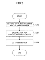
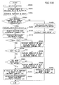
- Fig. 2 shows a procedure, starting from a scheduling process of calculating scheduling coefficients, to an UL TFR selection process of determining the transport format and RBs to be allocated.
- an UL MAC maximum multiplexing number N ULMAx is set in the base station apparatus 200.
- the UL MAC maximum multiplexing number N ULMAX is the maximum multiplexing number in one sub-frame of the Uplink Shared Channel (UL-SCH) (including both the UL-SCH for initial transmission and the UL-SCH for retransmission) to which dynamic scheduling is applied and is designated via the external input interface (I/F).
- UL-SCH Uplink Shared Channel
- I/F external input interface
- step S204 Calculation for Scheduling coefficients is performed in the base station apparatus 200.
- the user equipment terminals (UEs) to which radio resources are to be allocated according to dynamic scheduling in the corresponding sub-frame are selected.
- Uplink Transport format and Resource selection is performed, as described below, with respect to the user equipment terminals (UEs) to which radio resources are to be allocated according to dynamic scheduling in the corresponding sub-frame.
- the number of user equipment terminals (UEs) to which radio resources are to be allocated according to dynamic scheduling in the corresponding sub-frame is defined as N UL-SCH .
- step S208 Uplink Transport format and Resource selection is performed in the base station apparatus 200.
- the base station apparatus 200 reserves radio resources (RBs) for the Physical Random Access Channel (PRACH), reserves prohibited radio resources (RBs) or guard RBs, reserves radio resources (RBs) for the UL-SCH to which persistent scheduling is applied, and then determines a transmission format for the UL-SCH to which dynamic scheduling is applied and allocates radio resources for the UL-SCH to which dynamic scheduling is applied (including for both initial transmission and retransmission).
- RBs radio resources for the Physical Random Access Channel
- RBs Radio resources
- guard RBs reserves radio resources (RBs) for the UL-SCH to which persistent scheduling is applied
- Fig. 3 shows a process of selecting candidates for the user equipment terminals (UEs) to which radio resources are to be allocated according to dynamic scheduling, by calculating the scheduling coefficients.
- the base station apparatus 200 performs the following processes with respect to all the user equipment terminals (UEs) in an LTE active state (in an RRC (Radio Resource Control) connected state).
- RRC Radio Resource Control
- step S304 Renewal of HARQ (Hybrid Automatic Repeat reQuest) Entity Status is performed.
- HARQ Hybrid Automatic Repeat reQuest
- the maximum number of retransmission times is "the largest value selected from the maximum numbers of retransmission times of all the logical channels which may be used by the user equipment terminal (UE) for transmission".
- the user equipment terminal performs HARQ based on the maximum number of retransmission times of the logical channel with the highest priority class among logical channels to be multiplexed in the MAC PDU. For example, when the user equipment terminal uses the shared channel to transmit the transport channel including two or more logical channels, the user equipment terminal determines that the maximum number of retransmission times of the transport channel is the maximum number of retransmission times of the logical channel with the highest priority level among the two or more logical channels.
- step S306 HARQ Retransmission Check is performed. It is determined whether the user equipment terminal (UE) has data to be retransmitted in the corresponding sub-frame.
- the "data to be retransmitted" refer to retransmission data which satisfy the following four conditions:
- the process of the HARQ Retransmission Check returns "Retransmission”. Otherwise, the process of the HARQ Retransmission Check returns "No retransmission”.
- the process goes to step S310 in which Measurement Gap Check is performed.
- the base station apparatus Since the maximum number of retransmission times of the UL-SCH is determined for each priority class of the logical channel, the base station apparatus (eNB) performs the process assuming that the maximum number of retransmission times is the largest value selected from the maximum numbers of retransmission times of all the logical channels which may be used for transmission.
- N Retransmission is incremented by one in step S308 (N Retransmission ++), and then the user equipment terminal (UE) is excluded from a target of the scheduling process for initial transmission.
- the persistent resources are released.
- the RBs corresponding to the persistent resources are used for UL TFR Selection for the UL-SCH to which dynamic scheduling is applied.
- step S310 Measurement Gap Check is performed.
- the base station apparatus 200 does not allocate the Uplink Shared Channel (RBs for the Uplink Shared Channel) to the user equipment terminal (UE), when the time interval during which the user equipment terminal (UE) measures a cell with a different frequency overlaps a time frame in which the Physical Downlink Control Channel for the Uplink Shared Channel is transmitted in downlink, a time frame in which the shared channel is received, or a time frame in which acknowledge information for the Uplink Shared Channel is transmitted.
- the UL Scheduling Grant for the Uplink Shared Channel is transmitted via the Physical Downlink Control Channel.
- the cell with the different frequency may be a cell of the Evolved UTRA and UTRAN system or a cell of another system such as GSM, WCDMA, TDD-CDMA, CDMA-2000, or WiMAX.
- the process of the Measurement Gap Check returns NG (failed).
- the Measurement gap refers to a time interval during which the user equipment terminal (UE) measures a cell with a different frequency for the purpose of different-frequency handover or different-system handover. During the time interval, communications cannot be performed and therefore, the user equipment terminal (UE) cannot receive the Physical Downlink Control Channel. For the same reason, the user equipment terminal (UE) cannot transmit the Uplink Shared Channel and cannot receive the ACK/NACK.
- the result of the Measurement Gap Check is determined as NG, the user equipment (UE) terminal is excluded from a target of the scheduling process.
- the Measurement Gap Check is not performed for third transmission or later.
- the Measurement Gap Check is performed for the initial transmission and second transmission in this example, it may be performed for the initial transmission, second transmission, and third transmission.
- step S312 DRX (discontinuous reception) Check is performed.
- DRX discontinuous reception
- the user equipment terminal (UE) performs DRX, that is, when the user equipment terminal (UE) is in a DRX mode, the Uplink Shared Channel (RBs for the Uplink Shared Channel) is not allocated to the user equipment terminal (UE).
- the process of the DRX Check returns NG (failed). Otherwise, the process of the DRX Check returns OK.
- the result of the DRX Check is determined as NG, the user equipment terminal (UE) is excluded from a target of the scheduling process for initial transmission.
- step S314 Uplink Synchronization Check (UL Sync Check) is performed.
- the Uplink Shared Channel RBs for the Uplink Shared Channel
- the process of the UL Sync Check returns NG (failed).
- the process of the UL Sync Check returns OK.
- the base station apparatus (eNB) 200 performs the following two kinds of detections (determinations) for the uplink synchronization state with respect to each user equipment terminal (UE) 100 n in the RRC_connected state.
- the base station apparatus (eNB) 200 performs power detection of a Sounding RS (Reference signal) of the user equipment terminal (UE) within a range of Window 1 determined by taking the cell radius into consideration and having a similar size of a Window to wait for a RACH preamble. Namely, when a metric used in the power detection of the user equipment terminal exceeds a predetermined threshold, the result of the power detection is determined as OK. Otherwise, the result of the power detection is determined as NG. Further, a reflection time (which is a time period required to determine OK or NG) in the power detection is typically in a range from 200 ms to 1,000 ms while the Sounding RS is continuously received.
- a Sounding RS Reference signal
- the base station apparatus (eNB) 200 performs FFT timing detection to detect whether a signal of the user equipment terminal (UE) is included within a range of Window 2 defined based on an FFT timing and a CP (Cyclic Prefix) length. Therefore, when the signal of the user equipment terminal (UE) is included in the Window 2, the result of the FFT timing detection is determined as OK. When there is no main path of the user equipment terminal (UE), the result of the FFT timing detection is determined as NG. Further, the reflection time (which is a time period required to determine OK or NG) in the FFT timing detection is typically in a range from 1 ms to 200 ms while the Sounding RS is continuously received.
- the "Out of Synchronization: Type A” refers to a synchronization state of the user equipment terminal (UE) in which the result of the power detection is determined as OK and the result of the FFT timing detection is determined as NG.
- the "Out of Synchronization: Type B” refers to a synchronization state of the user equipment terminal (UE) in which the result of the power detection is determined as NG and the result of the FFT timing detection is determined as NG.
- the process of the HARQ Retransmission Check in step S306 is performed before the process of the UL Sync Check in step S314. Accordingly, when the result of the HARQ Retransmission Check is determined as "Retransmission", the retransmitted UL-SCH is received with respect to the user equipment terminal (UE) even if the result of the UL Sync Check is determined as NG.
- step S316 Received SIR Check is performed.
- the base station apparatus 200 when the base station apparatus 200 does not receive the reference signal from the user equipment terminal (UE), the base station apparatus 200 does not allocate the Uplink Shared Channel (RBs for the Uplink Shared Channel) to the user equipment terminal (UE).
- RBs for the Uplink Shared Channel RBs for the Uplink Shared Channel
- the base station apparatus 200 determines whether at least one Sounding Reference Signal is received from the user equipment terminal (UE) within "all the RBs in which the Sounding Reference Signal may be transmitted", which is defined by the transmission bandwidth and the frequency hopping interval for the Sounding Reference Signal.
- the process of the Received SIR Check returns OK. Otherwise, the process of the Received SIR Check returns NG (failed).
- the result of the Received SIR Check is determined as NG, the user equipment terminal (UE) is excluded from a target of the scheduling process.
- the base station apparatus 200 determines whether at least one Sounding Reference Signal is received within "all the RBs in which the Sounding Reference Signal may be transmitted". Alternatively, the base station apparatus 200 may determine whether at least one Sounding Reference Signal is received in at least one of "all the RBs in which the Sounding Reference Signal may be transmitted”.
- the Sounding Reference Signal refers to a signal used for measurement of channel quality for the purpose of uplink frequency scheduling.
- Persistent scheduling is a scheduling scheme for periodically allocating data transmission opportunities in accordance with a data type or features of the application to transmit/receive data.
- the data type may include data of Voice Over IP, Streaming data or the like.
- the Voice Over IP or the Streaming corresponds to the application.
- step S3108 it is determined whether the user equipment terminal (UE) has a logical channel to which persistent scheduling is applied.
- the process goes to step S320 in which Persistent Scheduling Sub-frame Check is performed. Otherwise, the process goes to step S328 in which UL Low/High Fd Check is performed.
- step S320 Persistent Scheduling Sub-frame Check is performed.
- the process goes to step S322 in which Assign/Release Check is performed. Otherwise, the process goes to step S328 in which UL Low/High Fd Check is performed.
- the persistent resources refer to resource blocks which are reserved for persistent scheduling.
- step S322 Assign/Release Check is performed. It is determined whether the base station apparatus 200 receives from the user equipment terminal (UE) a Release request for the persistent resources which are allocated to the user equipment terminal (UE) in the corresponding sub-frame. When the base station apparatus receives the Release request, the process goes to step S32.6 in which Persistent Resource Release is performed. Otherwise, the process goes to step S324 in which Persistent Resource Reservation is performed.
- step S324 Persistent Resource Reservation is performed.
- persistent resources to be allocated to the user equipment terminal's logical channel to which persistent scheduling is applied are reserved.
- Scheduling Coefficient Calculation described in Section 4.1.10 is also performed with respect to the user equipment terminal (UE) to which persistent resources are to be allocated in the corresponding sub-frame. Further, when radio resources are allocated to the logical channel to which dynamic scheduling is applied in the corresponding sub-frame, the user equipment terminal (UE) multiplexes the logical channel to which persistent scheduling is applied and the logical channel to which dynamic scheduling is applied, and then transmits the MAC PDU (UL-SCH).
- radio resources may not be allocated to the logical channel to which dynamic scheduling is applied in the corresponding sub-frame with respect to the user equipment terminal (UE) to which persistent resources are to be allocated in the corresponding sub-frame.
- the process goes to step S336 after Persistent Resource Reservation in step S324.
- step 326 Persistent Resource Release is performed.
- the base station apparatus 200 uses the released resources (the resources to be allocated according to persistent scheduling) as the resources to be allocated according to dynamic scheduling.
- the base station apparatus 200 releases persistent resources to be allocated in the corresponding sub-frame to the user equipment terminal's logical channel to which persistent scheduling is applied. It should be noted that the persistent resources are released only in the corresponding sub-frame and the Assign/Release Check is performed again in the next allocation timing of persistent resources.
- step S328 the uplink transmission type is checked (UL Low/High Fd Check is performed). In this step, it is determined whether the UL transmission type for the user equipment terminal (UE) is Low Fd or High Fd.
- the transmission type is independently managed in downlink and uplink.
- the UL transmission type is determined as Low Fd. Otherwise, the UL transmission type is determined as High Fd.
- Pathloss a value reported from the user equipment terminal (UE) by means of a Measurement report or the like may be used.
- a value calculated based on both UPH (UE Power Headroom) reported from the user equipment terminal (UE) and the received level of the Sounding Reference Signal transmitted from the user equipment terminal (UE) may be used.
- the estimated value of Fd the value reported from the user equipment terminal (UE) by means of the Measurement report or the like may be used.
- the estimated value of Fd a value calculated based on the time correlation value of the Sounding Reference Signal transmitted from the user equipment terminal (UE) may be used.
- the transmission type is determined based on both the value of Pathloss and the estimated value of Fd.
- the transmission type may be determined based only the value of Pathloss or only the estimated value of Fd.
- step S330 Buffer Status Check is performed.
- the base station apparatus does not allocate the Uplink Shared Channel (RBs for the Uplink Shared Channel) to the user equipment terminal (UE), when the user equipment terminal (UE) does not have data to be transmitted.
- RBs for the Uplink Shared Channel the Uplink Shared Channel
- available data to be transmitted refers to available data to be initially transmitted.
- available data to be initially transmitted When the amount of data in the UL Buffer is greater than zero (0), it is determined that there are "available data to be initially transmitted”. Please refer to Section 4.1.10.2 for the definition of the amount of data in the UL Buffer.
- a similar process can be applied to the case where three or more types of logical channel groups are used. Also, a similar process can be applied to the case where only one type of logical channel group is used.
- the base station apparatus When the base station apparatus receives from the user equipment terminal (UE) "allocation request for the PUSCH: REQUESTING" by means of the Scheduling request and uplink radio resources (PUSCH) have not been allocated to the user equipment terminal (UE) since the base station apparatus has received the Scheduling request, namely, when the Uplink Shared Channel (RBs for the Uplink Shared Channel) is not allocated to the user equipment terminal (UE), the following scheduling process is performed assuming that there are available data to be transmitted with respect to the logical channel group corresponding to the high priority group.
- the base station apparatus When the base station apparatus does not receive information about the amount of data in the buffer (data including the Buffer Status Report) at the reception timing of the PUSCH (the UL-SCH as the transport channel), even though the base station apparatus (eNB) allocates uplink radio resources (PUSCH) in response to the Scheduling request or allocates the Uplink Shared Channel (RBs for the Uplink Shared Channel), the base station again assumes that the base station apparatus receives from the user equipment terminal (UE) the "allocation request for the PUSCH: REQUESTING" by means of the Scheduling request and uplink radio resources (PUSCH) have not been allocated to the user equipment terminal (UE) since the base station apparatus has received the Scheduling request. This assumption is made when the base station apparatus does not receive information about the amount of data in the buffer (data including the Buffer Status Report) at the timing of initial transmission without waiting for the maximum number of retransmission times.
- the user equipment terminal When the result of the Buffer Status Check is determined as NG, the user equipment terminal (UE) is excluded from a target of the scheduling process for initial transmission.
- a logical channel group with the highest priority level is selected based on the following selection logic and the process goes to step S332 in which Scheduling Coefficient Calculation is performed.
- the base station apparatus calculates the scheduling coefficients based on the data type with the highest priority level among data types retained by the user equipment terminal.
- Selection logic 1 When there are available data to be transmitted in the high priority group, the logical channel group corresponding to the high priority group is defined as the logical channel group with the highest priority level.
- Selection logic 2 When there are no available data to be transmitted in the high priority group (when there are available data to be transmitted only in the low priority group), the logical channel group corresponding to the low priority group is defined as the logical channel group with the highest priority level.
- step S332 Scheduling Coefficient Calculation is performed.
- the scheduling coefficients are calculated based on the following evaluation equation.
- Tables 1-1 and 1-2 show parameters set via the external interface (I/F).
- Table 2 shows parameters for each logical channel group of the user equipment terminal (UE).
- [Table 1-1] List of input parameters for the scheduler (The subscript LCG refers to the logical channel group.) No Parameter name Set with respect to each Remarks 1
- a LCG Logical channel group This is a Priority Class priority level coefficient based on the logical channel group.
- 2 F LCG (t No_allocated ) Logical channel group This is a transmission resource allocation priority level coefficient used to preferentially transmit data to UE to which transmission resources are not allocated according to dynamic scheduling.
- a time interval t No_allocated during which transmission resources are not allocated according to dynamic scheduling is defined as an elapsed time from the timing when the preceding CRC result of the UL-SCH including logical channels belonging to the corresponding logical channel group is determined as OK. If the CRC result of the UL-SCH including logical channels belonging to the corresponding logical channel group is never determined as OK, the time interval t No_allocated is defined as an elapsed time from the timing when information about the amount of data in the buffer (the amount of data is other than zero (0)) with respect to the logical channel group is reported from the user equipment terminal. This value is set based on the buffer residence time t No_allocated as follows.
- Th LCG (No_Allocated) Priority class This is a threshold related to the time interval during which transmission resources are not allocated according to dynamic scheduling.
- G(flag SR ) UE This is a Scheduling request priority level coefficient given to preferentially transmit data to UE from which the base station apparatus receives "allocation request for the PUSCH: REQUESTING"" by means of the Scheduling request and to which uplink radio resources (PUSCH) have not been allocated since the base station apparatus has received the Scheduling request.
- H(flag gap_control ) UE This is a gap control priority level coefficient used to preferentially transmit data to UE in which a Measurement gap control mode is ON to measure a cell with a different frequency. In the corresponding sub-frame, this value is set based on a value flag gap_cnntrol of the corresponding UE.
- flag gap_control 0
- H(1) 10
- Table 1-2 List of input parameters for the scheduler (The subscript LCG refers to the logical channel group.) No Parameter name Set with respect to each Remarks 6 R PC (target) Logical channel group This is a target data rate (bits/sub-frame).
- Scheduling priority handling mode Cell This is a parameter to select a scheduling mode among logical channel groups. This value is set as a value 0 or 1. 0 is a mode used to preferentially schedule the high priority group regardless of the values of scheduling coefficients. 1 is a mode used to schedule based on the values of scheduling coefficients. [Table 2] List of input parameters for the scheduler (The subscript LCG refers to the logical channel group.) No. Parameter name Remarks 1 R n This parameter indicates an Instantaneous transmittable Data Rate (bits/sub-frame) of UE #n, as described below.
- R n UL_Table_TF_SIZE(RB_all, ⁇ SIR estimated ⁇ ) where RB_all is the number of RBs across the system band. Further, SIR estimated is calculated across the system band. Alternatively, SIR estimated may be the maximum value of plural sets of SIR estimated which are calculated across narrower bands. Alternatively, SIR estimated may be selected, based on the transmission type, from both the value calculated across the system band and the maximum value of plural sets of SIR estimated which are calculated across narrower bands. 2 R n,k This parameter indicates an Average Data Rate (bits/sub-frame) of a logical channel group #k of UE #n.
- R ⁇ n , k TTI ⁇ n , k * R ⁇ n , k ⁇ TTI - 1 + 1 - ⁇ n , k * r n , k r n,k :instantaneous data rate
- ⁇ n,k forgetting coefficient which is a variable changing for each calculation period, as described in Section 4.1.10.1. Calculation of R n,k is performed in every sub-frame based on an updating timing (Section 4.1.10.1) with respect to not only a logical channel group with the highest priority level but also any other logical channel groups.
- This parameter indicates a time-average value of allocation frequency of UE #n.
- Freq This parameter indicates a value by averaging freq n among user equipment terminals (UEs). Averaging is performed with respect to only user equipment terminals (UEs) in which the amount of data in the UL Buffer for the high priority group or the low priority group is not zero (0) in the corresponding sub-frame. Namely, it is calculated as follows.
- Equation 1 the scheduling coefficient C n of the logical channel #h with the highest priority level of the user equipment terminal (UE) #n is calculated according to the following equation (1-1) ([Equation 1]).
- the base station apparatus may select the user equipment terminal based on a signal (Scheduling request) by means of which the user equipment terminal requests allocation of the Uplink Shared Channel (RBs for the Uplink Shared Channel).
- the base station apparatus may calculate a coefficient representing a priority level for allocating radio resources based on at least one of a priority class of data; radio quality of the reference signal transmitted from the user equipment terminal (for example, SIR of the Sounding Reference Signal); a time duration during which the shared channel (RBs for the shared channel) is not allocated; whether the base station apparatus receives the Scheduling request; a frequency of allocation occurrences; an average transmission rate; and a target transmission rate.
- the scheduling coefficient C n of the logical channel #h with the highest priority level of the user equipment terminal (UE) #n may be calculated according to the following equation (1-2) ([Equation 2])
- C n A highest ⁇ ⁇ PL ⁇ R n ⁇ 1 + ⁇ highest No_allocated ⁇ F highest t No_allocated ⁇ G flag SR ⁇ H flag gap_control ⁇ exp ⁇ highest freq ⁇ Freq - freq n + ⁇ highest rate ⁇ R n , highest target - R ⁇ n , highest
- flag gap_control is a flag indicating whether the user equipment terminal (UE) #n is in a Measurement gap control mode.
- the Measurement gap control mode indicates whether a Measurement gap for measuring a cell with a different frequency is being applied.
- the Measurement gap control mode is ON, the Measurement gap is set at a predetermined timing. The Measurement gap is set by the base station apparatus 200.
- step S310 when the Measurement gap control mode is ON and when the time frame in which the Physical Downlink Control Channel for the Uplink Shared Channel is transmitted in downlink is included in the Measurement gap or the time frame in which the shared channel is received or the time frame in which acknowledge information for the Uplink Shared Channel is transmitted is included the Measurement gap, this process in step S332 is not performed.
- the Measurement gap control mode when the Measurement gap control mode is ON and when this process in step S332 is to be performed, the sub-frame is at the timing when the same (original) frequency signal is transmitted and received in a mode when a cell with a different frequency is being measured. Namely, due to the term "H(flag gap_control )", it may become possible to preferentially allocate the shared channel to the user equipment terminal transmitting and receiving the same (original) frequency in a mode when a cell with a different frequency is being measured.
- an Average Data Rate is measured.
- the Average Data Rate is calculated using the following equation (2) ([Equation 3]).
- ⁇ n,k min ⁇ 1 - 1 / N n , k , ⁇ PCn , k
- An updating cycle of the Average Data Rate is based on "every sub-frame where the amount of data in the UL Buffer is not zero (0) for each logical channel group”. Further, r n,k is calculated as "the size of the MAC SDU (including for both initial transmission and retransmission) transmitted from the user equipment terminal (UE)". Namely the calculation of the Average Data Rate is performed based on any of the following operations in the sub-frame when the Average Data Rate is to be updated.
- the size of the retransmitted MAC SDU is calculated retroactively to previous transmissions of the UL-SCH, when the CRC result of the UL-SCH including logical channels belonging to the corresponding logical channel group is OK.
- the Average Data Rate is calculated when the result of the Received SIR Check is OK and the condition of updating the Average Data Rate is matched. Namely the calculation is started after at least one Sounding Reference Signal is received across the whole band.
- the amount of data in the UL Buffer is defined as follows.
- Buffer n,k denotes the amount of data in the buffer for the logical channel group #k of the user equipment terminal (UE) #n, which is calculated based on the Buffer Status Report reported from the user equipment terminal (UE).
- OK j denotes the sum of data sizes for the logical channel group #k of the user equipment terminal (UE) #n, which has been included in the UL-SCH where the CRC result is OK since the timing of making the Buffer Status Report (until the current timing).
- the base station apparatus calculates the amount of data in the buffer of the user equipment terminal based on both information about the amount of data in the buffer (Buffer Status Report (BSR)) reported from the user equipment terminal and the amount of data which has been received from the user equipment terminal since the base station apparatus has received the information.
- BSR Buffer Status Report
- step S334 N Scheduling indicating the number of user equipment terminals (UEs) for which the scheduling coefficient is calculated is incremented by one.
- step S336 a value of "n" indicating the index of the user equipment terminal (UE) is incremented by one.
- step S3308 it is determined whether the value of "n" is less than or equal to N. When it is determined that the value of "n" is less than or equal to N, the process goes back to step S304.
- step S340 in which UE Selection is performed.
- the user equipment terminal (UE) to which radio resources are to be allocated according to dynamic scheduling (only for initial transmission) is selected in the corresponding sub-frame.
- N Scheduling denotes the number of user equipment terminals (UEs) for which the scheduling coefficient is calculated (see Fig. 3 ).
- N retransmission denotes the number of user equipment terminals (UEs) which perform retransmission in the corresponding sub-frame (see Fig. 3 ).
- N UL - SCH , tmp min ⁇ N Scheduling , N ULMAX - N retransmission
- the "user equipment terminals (UEs) to which radio resources are to be allocated according to dynamic scheduling" are selected as follows based on the value of the Scheduling priority handling mode.
- Top N UL-SCH "user equipment terminals (UEs) to which radio resources are to be allocated according to dynamic scheduling" are selected in descending order of the scheduling coefficients calculated in Section 4.1.10 for each logical channel group, by prioritizing the high priority groups. Namely, the user equipment terminals (UEs) are selected according to the following order. H ⁇ i ⁇ g ⁇ h 1 ⁇ s ⁇ t - > H ⁇ i ⁇ g ⁇ h 2 ⁇ s ⁇ t - > ... - > L ⁇ o ⁇ w 1 ⁇ s ⁇ t - > L ⁇ o ⁇ w 2 ⁇ n ⁇ d - > ...
- Top N UL-SCH "user equipment terminals (UEs) to which radio resources are to be allocated according to dynamic scheduling" are selected in descending order of the scheduling coefficients calculated in Section 4.1.10 regardless of the logical channel group.
- the radio resources may be allocated to the user equipment terminal having a greater calculated scheduling coefficient value, and thereby it may become possible to determine the user equipment terminals to which the radio resources (Uplink Shared Channel) are to be allocated based on a priority level of data; uplink radio quality; a time duration during which the shared channel (RBs for the shared channel) is not allocated; whether the base station apparatus receives the Scheduling request; a frequency of allocation occurrences; an average transmission rate; or a target transmission rate.
- n is an index of the user equipment terminals (UE index).
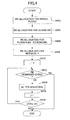
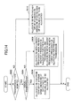
- Uplink TFR Selection (UL TFR Selection) performed in step S208 is described with reference to Fig. 4 .
- Fig. 4 shows a procedure of UL TFR Selection.
- the base station apparatus 200 reserves radio resources (RBs) for the Physical Random Access Channel (PRACH), reserves prohibited radio resources (RBs) or guard RBs, reserves radio resources (RBs) for the UL-SCH to which persistent scheduling is applied, and then determines a transmission format for the UL-SCH to which dynamic scheduling is applied and allocates radio resources for the UL-SCH to which dynamic scheduling is applied (including for both initial transmission and retransmission).
- RBs Physical Random Access Channel
- RBs Radio resources
- guard RBs reserves radio resources (RBs) for the UL-SCH to which persistent scheduling is applied
- step S402 resource block allocation for the Physical Random Access Channel (PRACH) and the Physical Uplink Control Channel (PUCCH) to be frequency-multiplexed with the Physical Uplink Shared Channel (PUSCH) (RB allocation for PRACH and PUCCH) is performed.
- radio resources are allocated to the Random Access Channel (RACH) and the Physical Uplink Control Channel (PUCCH) before radio resources are allocated to the shared channel.
- radio resources (RBs) for the PRACH and N RACH RBs on both sides of the PRACH are reserved (6 + 2*N RACH RBs are reserved in total).
- the radio resources (RBs) for the PRACH and N RACH RBs on both sides of the PRACH (6 + 2*N RACH RBs in total) are excluded from candidates for RBs to be allocated to the UL-SCH to which dynamic scheduling is applied.
- N RACH is a value designated via the external input interface (I/F).
- N RACH is selected from 0, 1, 2, and 3.
- the PRACH preamble corresponds to a Message-1 in the random access procedure.
- the number of resource blocks in which the PRACH preamble is transmitted is equal to six (6).
- radio resources (RBs) for the Physical Uplink Control Channel (PUCCH) are reserved.
- the radio resources (RBs) to be allocated to the Physical Uplink Control Channel (PUCCH) are excluded from candidates for RBs to be allocated to the UL-SCH to which dynamic scheduling is applied.
- step S404 RB allocation for Guard RBs is performed.
- the system is frequency-adjacent (adjacent in the frequency direction) to a heterogeneous radio communication system (WCDMA system), for example, radio resources other than the resource placed at the end of the system bandwidth are allocated.
- WCDMA system heterogeneous radio communication system
- Guard RBs are reserved.
- the Guard RBs are excluded from candidates for RBs to be allocated to the UL-SCH to which dynamic scheduling is applied.
- the heterogeneous radio communication system is the WCDMA system.
- the heterogeneous radio communication system may be a GSM system, a CDMA-2000 system, a PHS system, or the like.
- the Guard RBs are implemented as guard bands for the purpose of reducing adjacent channel interference with a frequency-adjacent system. Two sets of Guard RBs may be reserved for both ends of adjacent systems. It should be noted that the Physical Uplink Control Channel (PUCCH) is mapped to the end of the system band regardless of the presence or absence of the Guard RBs.
- PUCCH Physical Uplink Control Channel
- step S406 RB allocation for Persistent Scheduling is performed.
- allocation according to persistent scheduling is performed before allocation according to dynamic scheduling is performed.
- radio resources (RBs) for the persistent resources which are reserved in Section 4.1.7.3, are reserved.
- the base station apparatus may perform the following three processes, in order to handle collisions from plural user equipment terminals (UEs) via the PUSCH due to either "miss detection of the UL Scheduling Grant via the Physical Downlink Control Channel” or “false detection of acknowledgement information (UL ACK/NACK) for the Uplink Shared Channel (False ACK (NACK -> ACK) detection)" by the user equipment terminal (UE).
- the base station apparatus performs reception of the UL-SCH according to dynamic scheduling at the reception timing. Then, the base station apparatus performs power detection using only RBs which do not overlap the radio resources (RBs) corresponding to the persistent resources. When the result of the power detection is DTX (when no transmission of the UL-SCH is detected), the base station apparatus performs reception of the UL-SCH according to persistent scheduling.
- the base station apparatus When the radio resources (RBs) for persistent scheduling are found to collide with "radio resources (RBs) which are allocated to other user equipment terminals (UEs) according to dynamic scheduling" and when the CRC result for the "radio resources (RBs) which are allocated to other user equipment terminals (UEs) according to dynamic scheduling" is NG, the base station apparatus transmits the ACK for the "UL-SCH according to persistent scheduling" to the user equipment terminal (UE) regardless of the CRC result.
- step S408 resource block allocation for the Message-3 in the random access procedure (RB allocation for Message-3 (RACH)) is performed.
- radio resources are allocated to the Message-3(s) in the random access procedure before radio resources are allocated to the shared channel.
- Radio resources (RBs) for the Message-3s in the random access procedure are reserved. Specifically, radio resources (RBs) for the Message-3s in the random access procedure (including for both initial transmission and retransmission) are excluded from candidates for RBs to be allocated to the UL-SCH to which dynamic scheduling is applied.
- Message-3s in the random access procedure are merely referred to as Message-3s.
- the RB allocation for the Message-3s for initial transmission is performed according to the following five-step procedure.
- the RB allocation for retransmission is the same as the RB allocation for initial transmission.
- the Hopping mode is a parameter designated via the external input interface (I/F).
- the Message-3 sets are indexed as #a, #b, #c, ... (the Message-3 set #a includes the Message-3s #0 and #1, the Message-3 set #b includes the Message-3s #2 and #3, and so on).
- the last Message-3 constitutes one Message-3 set.
- the base station apparatus allocates "RBs which have reflective symmetry at the center of the system band" to the Message 3 sets in the order of #a, #b, #c, .... Specifically, the base station apparatus allocates RBs to the Message-3 sets in the order of #a, #b, #c, ... beginning from the ends of the system band.
- the number of RBs allocated to the Message-3s is determined based on quality information. For example, when the quality information indicates "high quality", two RBs are allocated. For example, when the quality information indicates "low quality", four RBs are allocated. Alternatively, the number of RBs may be determined regardless of quality information. For example, this quality information is included in the Message-1 in the random access procedure.
- the base station apparatus uses a larger number of RBs to allocate the "RBs which have reflective symmetry at the center of the system band".
- the base station apparatus 200 may notify the user equipment terminal that the Message-3s are transmitted with hopping, as information included in the Uplink Scheduling Grant to be mapped to the Physical Downlink Control Channel (PDCCH), for example.
- PDCCH Physical Downlink Control Channel
- the base station apparatus does not allocate RBs which are placed outside the RBs allocated to the Message-3s to the UL-SCH to which dynamic scheduling is applied. In addition, when the number of Messsage-3s is odd-numbered, the base station apparatus does not allocate the RBs used for transmitting the last Message-3 to the UL-SCH to which dynamic scheduling is applied.
- the base station apparatus allocates RBs to Message-3s as follows.
- the number of RBs allocated to the Message-3s is determined based on quality information. For example, when the quality information indicates "high quality", two RBs are allocated. For example, when the quality information indicates "low quality", four RBs are allocated. Alternatively, the number of RBs may be determined regardless of quality information. For example, this quality information is included in the Message-1 in the random access procedure.
- the base station apparatus does not transmit a Message-2 (RACH response) in the random access procedure to the user equipment terminal (UE) which has the Message-3 to which no RB is allocated.
- the base station apparatus may transmit the Message-2 (RACH response) in the random access procedure in the next sub-frame.
- step S410 RB Remaining Check is performed. It is determined whether there are available RBs to be allocated to the UL-SCH to which dynamic scheduling is applied. When there are available RBs to be allocated to the UL-SCH, the process of the RB Remaining Check returns OK. Otherwise, the process of the RB Remaining Check returns NG (failed). When the result of the RB Remaining Check is determined as NG, the process of the UL TFR Selection comes to an end.
- the "available RBs to be allocated to the UL-SCH to which dynamic scheduling is applied” correspond to RBs other than the RBs allocated to the Physical Random Access Channel (PRACH) and the Physical Uplink Control Channel (PUCCH), the Guard RBs, the RBs allocated to the UL-SCH to which persistent scheduling is applied, the RBs allocated to the Message-3 in the random access procedure, and the RBs allocated to the UL-SCH to which dynamic scheduling is applied after TFR Selection (including for both retransmission and initial transmission).
- the total number of "available RBs to be allocated to the UL-SCH to which dynamic scheduling is applied is defined as N remain (RB) .
- the RBs allocated to the UL-SCH to which dynamic scheduling is applied after TFR Selection correspond to the RBs determined in step S414, when the value of "j" is less than the current value in the loop process with respect to the index "j" composed of steps S410, S414, S416, and S418.
- step S414 UL TFR Selection is performed.
- the base station apparatus determines the transport format for the "user equipment terminal (UE) to which radio resources are to be allocated according to dynamic scheduling", which is determined in Section 3.2, and allocates RBs.
- UE user equipment terminal
- step S414 Setting of RB allocation mode is performed.
- the UL RB allocation mode shown in Table 3 is a parameter designated via the external input interface (I/F).
- the loop process with respect to the index "j" is executed based on the selection order of user equipment terminals (UEs) specified by the UL RB allocation mode.
- [Table 3] UL RB allocation mode Mode Definition Mode-0 This is a normal RB allocation mode. In this mode, the following selection order of user equipment terminals (UEs) is used. (1st criterion) User equipment terminals (UEs) for retransmission are selected. Among these user equipment terminals (UEs), a higher selection order is assigned to a user equipment terminal (UE) with a longer elapsed time from initial transmission.
- the selection order is arbitrary determined.
- (2nd criterion) User equipment terminals for initial transmission are selected. Among these user equipment terminals (UFs), a higher selection order is assigned to the "candidates for the user equipment terminals (UEs) to which radio resources are to be allocated according to dynamic scheduling" determined in Section 4.1.11. Mode-1 This is a RB allocation mode in which RBs at the end of the system band are allocated to user equipment terminals with low path loss (Pathloss).
- (1st criterion) User equipment terminals for retransmission are selected. Among these user equipment terminals (UEs), a higher selection order is assigned to a user equipment terminal (UE) with lower path loss.
- (2nd criterion) User equipment terminals for initial transmission are selected. Among these user equipment terminals (UEs), a higher selection order is assigned to a user equipment terminal (UE) with lower path loss.
- Mode-2 This is a RB allocation mode in which RBs with a low frequency are allocated to user equipment terminals with high path loss (Pathless).
- (1st criterion) User equipment terminals for retransmission are selected. Among these user equipment terminals (UEs), a higher selection order is assigned to a user equipment terminal (UE) with higher path loss.
- (2nd criterion) User equipment terminals for initial transmission are selected. Among these user equipment terminals (UEs), a higher selection order is assigned to a user equipment terminal (UE) with higher path loss.
- Mode-3 This is a RB allocation mode in which RBs with high frequency are allocated to user equipment terminals with high path loss (Bathloss).
- (1st criterion) User equipment terminals for retransmission are selected. Among these user equipment terminals (UEs), a higher selection order is assigned to a user equipment terminal (UE) with higher path loss.
- (2nd criterion) User equipment terminals for initial transmission are selected. Among these user equipment terminals (UEs), a higher selection order is assigned to a user equipment terminal (UE) with higher path loss.
- Mode-2 and Mode-3 are selected.
- the base station apparatus allocates radio resources (frequency resources) for the shared channel, on the side of the WCDMA system and at the end of the system band, to a user equipment terminal with lower path loss.
- the base station apparatus allocates radio resources (frequency resources), on the side of the LTE system and at the end of the system band, to a user equipment terminal with higher path loss.
- Mode-1 is selected.
- the base station apparatus allocates radio resources (frequency resources) for the shared channel, at both ends of the system band, to a user equipment terminal with lower path loss.
- the base station apparatus allocates radio resources (frequency resources), at the center of the system band, to a user equipment terminal with higher path loss.
- Mode-0 is selected.
- radio resources are allocated based on reception power of the reference signal transmitted from the user equipment terminal or the like, as described below.
- step S414 RB allocation is performed.
- RBs are allocated to a j th "user equipment terminal (UE) to which radio resources are to be allocated according to dynamic scheduling".
- UE user equipment terminal
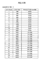
- Fig. 5 shows an example of a TF_Related_table.
- the TF_Related_table may store the correspondence between radio resources available for transmission of the Uplink Shared Channel, uplink radio quality information, and a transmission scheme used for transmission of the Uplink Shared Channel.
- the base station apparatus may determine the transmission scheme used for the Uplink Shared Channel, with reference to the TF_related_table, based on radio quality of the Sounding Reference Signal transmitted from the user equipment terminal (radio quality information calculated based on SIR, for example) and radio resources available for transmission of the Uplink Shared Channel.
- the RF_Related_table may store the data size used for the Uplink Shared Channel.
- the data size is determined to be a maximum value which satisfies a predetermined error rate, when uplink radio quality information and frequency resources available for the shared channel are fixed.
- the IF_Related_table may store, as the transmission scheme, the data size used for transmission of the Uplink Shared Channel, a modulation scheme used for the Uplink Shared Channel, and the amount of frequency resources used for the Uplink Shared Channel.
- available RBs to be allocated to the j th "user equipment terminal (UE) to which radio resources are to be allocated according to dynamic scheduling" are continuous.
- the "available RBs to be allocated” are determined as a set of RBs which has the maximum number of available RBs to be allocated among continuous available RBs to be allocated.
- the "RBs to be allocated” are determined as a set of RBs with a lower frequency.
- N allocated is determined as a maximum integer among integers which include only factors of 2, 3, 5 for the number of subcarriers and which are less than N allocated .
- RBs are allocated to the user equipment terminal (UE) among the “available RBs to be allocated to the UL-SCH to which dynamic scheduling (hereinafter called “available RBs to be allocated”)", which are determined in Section 5.5, beginning from the lowest frequency or the highest frequency until the number of RBs to be allocated to the user equipment terminal (UE) is greater than or equal to N allocated . In this case, hopping is not used.
- the base station apparatus Upon determining whether RBs are allocated beginning from the lowest frequency or the highest frequency, the base station apparatus selects RBs far from the center of the system band. When RBs have the same distance from the center of the system band, the base station apparatus allocates RBs beginning from the lowest frequency.
- the base station apparatus Upon determining whether RBs are allocated beginning from the lowest frequency or the highest frequency, the base station apparatus determines as follows based on whether the RBs include the previously allocated RBs.
- N small denotes the number of the previously allocated RBs, which are included in a set of RBs when the RBs are allocated beginning from the lowest frequency.
- N large denotes the number of the previously allocated RBs, which are included in a set of RBs when the RBs are allocated beginning from the highest frequency.
- N small N large , RBs are allocated beginning from the highest frequency.
- N small ⁇ N large , RBs are allocated beginning from the lowest frequency.
- the base station apparatus may allocate, to the shared channel used by the plural user equipment terminals, frequency resources (RBs) for retransmission at one end of the system bandwidth which are different from the frequency resources (RBs) used for previous transmission at the other end of the system bandwidth.
- RBs frequency resources
- RBs are allocated to the user equipment terminal (UE) among the “available RBs to be allocated to the UL-SCH to which dynamic scheduling is applied (hereinafter called “available RBs to be allocated”)", which are determined in Section 5.5, beginning from the lowest frequency or the highest frequency until the number of RBs to be allocated to the user equipment terminal (UE) is greater than or equal to N allocated . In this case, hopping is not used.
- the base station apparatus Upon determining whether RBs are allocated beginning from the lowest frequency or the highest frequency, the base station apparatus selects RBs as follows.
- the base station apparatus when the base station apparatus allocates frequency resources (RBs) to the shared channel used by plural user equipment terminals, beginning from the end of the system bandwidth, the base station apparatus may allocate, to the shared channel used by the plural user equipment terminals, a frequency resource (RB) with higher radio quality among frequency resources (RBs) at both ends of the system bandwidth.
- RB frequency resource
- This process is used for both initial transmission and retransmission.
- RBs are allocated to the user equipment terminal (UE) among the “available RBs to be allocated to the UL-SCH to which dynamic scheduling is applied (hereinafter called “available RBs to be allocated”)", which are determined in Section 5.5, beginning from the lowest frequency or the highest frequency until the number of RBs to be allocated to the user equipment terminal (UE) is greater than or equal to N allocated . In this case, hopping is not used.
- the base station apparatus Upon determining whether RBs are allocated beginning from the lowest frequency or the highest frequency, the base station apparatus selects RBs far from the center of the system band. When RBs have the same distance from the center of the system band, the base station apparatus allocates RBs beginning from the lowest frequency.
- RBs are allocated to the user equipment terminal (UE) among the “available RBs to be allocated to the UL-SCH to which dynamic scheduling is applied (hereinafter called “available RBs to be allocated”)", which are determined in Section 5.5, beginning from the lowest frequency until the number of RBs to be allocated to the user equipment terminal (UE) is greater than or equal to N allocated . In this case, hopping is not used.
- RBs are allocated to the user equipment terminal (UE) among the “available RBs to be allocated to the UL-SCH to which dynamic scheduling is applied (hereinafter called “available RBs to be allocated”)", which are determined in Section 5.5, beginning from the highest frequency until the number of RBs to be allocated to the user equipment terminal (UE) is greater than or equal to N allocated . In this case, hopping is not used.
- a set of RBs "to be allocated to the user equipment terminals (UE)" is called a Temporary RB group.
- SIR i,estimated in the Temporary RB group is defined as SIR estimated (RB) .
- the base station apparatus allocates, to the UL-SCH for retransmission, the same RBs as the RBs used for the previous transmission.
- the base station apparatus calculates a transmission power offset value ⁇ i,data (eNB) for the PUSCH relative to the Sounding RS, according to the following equation ( ⁇ i,data (eNB) is a offset value in terms of a power value per one RB).
- UPH UE Power Headroom
- B i,ref the transmission bandwidth of the Sounding Reference Signal
- B i,data the transmission bandwidth of the PUSCH
- Target i,RoT is calculated based on Pathloss i and Table 4.
- Pathloss i a value calculated based on the UPH may be used.
- Pathloss i a value of Pathloss reported as the Measurement report by the user equipment terminal (UE) may be used.
- UPH rate power of UE - transmission power of the Sounding Reference Signal
- the base station apparatus calculates the estimated SIR (SIR i,estimated ) of the UL-SCH according to the following equation (7) ([Equation 8]).
- SIR i , estimated SRSP i + ⁇ i , data eNB - Interference
- SRSP i denotes the reception level of the Sounding Reference Signal.
- Interference corresponds to the uplink interference level.
- the base station apparatus (eNB) adjusts the value of SIR i,estimated based on the following equation (8) ([Equation 9]), when the function for adjusting SIR estimated is "On".
- SIR_offset i is adjusted in an outer-loop manner based on the CRC result of the UL-SCH for the user equipment terminal (UE) #i, according to the following equation.
- SIR_offset i is adjusted in the outer-loop manner based on the CRC result of the UL-SCH in which the priority level of the logical channel group with the highest priority level is Z i,adjust (equation (10) ([Equation 11])).
- the priority level of the logical channel group with the highest priority level is different from Z i,adjust, SIR_offset i is not adjusted in the outer-loop manner.
- the priority level of the logical channel group with the highest priority level determined in Section 4.1.10 (Scheduling Coefficient Calculation) is used as the "priority level of the logical channel group with the highest priority level" in this process.
- SIR_offset i is adjusted for each user equipment terminal (UE).
- the priority level Z i,adjust in this process is adjusted via the MT (maintenance tool or external interface) for each user equipment terminal (UE).
- ⁇ adj (P) and BLER target (P) can be designated via the external input interface (I/F).
- the maximum value of SIR_offset i is defined as SIR_offset p (max) and the minimum value of SIR_offset i is defined as SIR_offset p (min) .
- SIR_offset i is continuously determined as the maximum value or the minimum value, the following calculation is not performed.
- the bandwidth for the Temporary RB group is defined as B i,data,tmp .
- the number of RBs included in B i,data is defined as the number of RBs Num RB to be allocated. Then, RBs in the Temporary RB group are removed, such that the number of RBs to be allocated to the user equipment terminal (UE) is not less than N UMRB , and the number of subcarriers includes only factors of 2, 3, and 5.
- the SIR (SIR estimated (RB) is adjusted by the offset based on the priority level of the logical channel group with the highest priority level.
- ⁇ LCG is designated via the external interface (I/F).
- the subscript LCG refers to the logical channel group.
- SIR estimated RB SIR estimated RB - ⁇ LCG
- Size UL_Table_TF_SIZE(RB_available, SIR estimated (RB) )
- ⁇ ULTFRS is a coefficient designated via the external interface (I/F).
- ⁇ ULTFRS is set to be 1.0 or 2.0.
- the base station apparatus determines that there are enough data in the UE buffer and all the RBs in the Temporary RB group are to be allocated to the user equipment terminal (UE).
- the base station apparatus determines that there are not enough data in the UE buffer and the number of RBs Num RB to be allocated is recalculated with reference to the VL_TF__related_table using ⁇ ULTFRS * (Buffer j,h (UL) + Buffer j,l (UL) (hereinafter described as Size buffer ) and SIR estimated (RB) as arguments.
- Num RB UL_Table_TF_RB(Size buffer , SIR estcommuned (RB) )
- Size UL_Table_TF_SIZE (Num RB , SIR estimated (RB) )
- Modulation UL_Table_TF_Mod(Num RB , SIR estimated (RB) )
- Num RB is determined as a minimum integer among integers which include only factors of 2, 3, and 5 for the number of subcarriers and which are greater than Num RB .
- RBs in the Temporary RB group are removed, such that the number of RBs to be allocated to the user equipment terminal (UE) is not less than Num RB .
- UE user equipment terminal
- the amount of data in the buffer of the user equipment terminal is less than the data size determined as the transmission scheme, the amount of frequency resources (the number of RBs) determined as the transmission scheme is decreased.
- Transmission power information ⁇ data to be reported to the user equipment terminal (UE) is adjusted based on the following equation, when the Uplink Scheduling Grant is specified via the Physical Uplink Control Channel for retransmission.
- ⁇ data (eNB) and 10*log 10 (B data /B ref ) are calculated at the retransmission timing.
- An offset value ⁇ LCG (HARQ) is designated via the external interface (I/F) for each logical channel group.
- ⁇ data ⁇ data eNB + 10 ⁇ log 10 B data B ref + ⁇ LCG HARQ
- the base station apparatus calculates transmission power of the shared channel based on the reception level of the uplink reference signal and the target reception level of the shared channel, and then performs the offset process for transmission power of the shared channel based on whether data are to be initially transmitted or to be retransmitted via the shared channel.
- step S416 the value of "j" is incremented by one.
- step S4108 it is determined whether the value of "j" is less than or equal to N UL-SCH . If the value of "j" is less than or equal to N UL-SCH (step S418: YES), the process returns to step S410. Otherwise (step S418: NO), the process comes to an end.
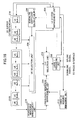
- the base station apparatus 200 includes a scheduling coefficient calculation unit 206 (as a selection unit), a transport format and resource block selection unit 210 (as an allocation unit), and a layer 1 processing unit 212.
- the scheduling coefficient calculation unit 206 performs the process of step S204. Specifically, the scheduling coefficient calculation unit 206 selects user equipment terminals (UEs) to which radio resources are to be allocated according to dynamic scheduling in the corresponding sub-frame and supplies the number of user equipment terminals (UEs) N UL-SCH to which radio resources are to be allocated according to dynamic scheduling to the transport format and resource block selection unit 210.
- UEs user equipment terminals
- N UL-SCH to which radio resources are to be allocated according to dynamic scheduling to the transport format and resource block selection unit 210.
- the transport format and resource block selection unit 210 performs the process of step S208. Specifically, the transport format and resource block selection unit 210 performs uplink transport format and resource selection. More specifically, the transport format and resource block selection unit 210 reserves radio resources (RBs) for the Physical Random Access Channel (PRACH), reserves prohibited radio resources (RBs) or guard RBs, reserves radio resources (RBs) for the UL-SCH to which persistent scheduling is to be applied, and then determines a transmission format for the UL-SCH to which dynamic scheduling is to be applied and allocates radio resources for the UL-SCH to which dynamic scheduling is to be applied (including for both initial transmission and retransmission).
- RBs radio resources
- PRACH Physical Random Access Channel
- guard RBs reserves radio resources (RBs) for the UL-SCH to which persistent scheduling is to be applied
- the layer 1 processing unit 212 performs a process related to the layer 1.
- the radio communication system 1000 which may be an Evolved UTRA (Universal Terrestrial Radio Access) and UTRAN (UTRA Network) system (a.k.a an LTE (Long Term Evolution) system or a super 3G system), includes a base station apparatus (eNB: eNode B) 200 and plural sets of user equipment (UE) 100 n (100 1 , 100 2 , 100 3 , ⁇ 1000 n ; n: an integer greater than zero (0)) (hereinafter, the user equipment (UE) may be referred to as a user equipment terminal(s)).
- the base station apparatus 200 is connected to an upper node such as an access gateway apparatus 300.
- the access gateway apparatus 300 is connected to a core network 400.
- the user equipment terminals 100 n are in communication with the base station apparatus 200 in a cell 50 based on the Evolved UTRA and UTRAN radio communication scheme.
- Each of the user equipment terminals (100 1 , 100 2 , 100 3 , ⁇ 100 n ) has the same configuration, functions, and status. Therefore, unless otherwise described, the term of user equipment terminals (UE) 100 n may be collectively used in the following descriptions.
- the OFDM (Orthogonal Frequency Division Multiplexing) scheme and the SC-FDMA (Single-Carrier Frequency Division Multiplexing Access) scheme are used in downlink and uplink communications, respectively.
- the OFDM scheme is a multi-carrier transmission scheme in which a frequency band is divided into plural sub-carriers having narrow frequency bands and data are mapped on each sub-carrier to be transmitted.
- the SC-FDMA scheme is a single-carrier transmission scheme in which a frequency band is divided so that different frequencies can be used among plural terminals and as a result, interference between terminals can be reduced.
- a Physical Downlink Shared Channel (PDSCH) shared among the user equipment terminals 100 n and a Physical Downlink Control Channel (PDCCH) are used.
- the Physical Downlink Control Channel (PDCCH) may also be called a DL L1/L2 Control Channel.
- transport format information and user information of the user to which the Physical Downlink Shared Channel is transmitted transport format information and user information of the user by which a Physical Uplink Shared Channel (PUSCH) is transmitted, acknowledge information of the PUSCH (or an Uplink Shared Channel (UL-SCH) as a transport channel), and the like are reported via the Physical Downlink Control Channel (PDCCH).
- User data are transmitted via the Physical Downlink Shared Channel.
- the user data are transmitted via a Downlink Shared Channel (DL-SCH) as a transport channel.
- DL-SCH Downlink Shared Channel
- the transport format information and user information of the user by which the Physical Uplink Shared Channel (PUSCH) is transmitted, which are transmitted via the Physical Downlink Control Channel (PDCCH), are called an Uplink Scheduling Grant.
- the Physical Uplink Shared Channel (PUSCH) that is shared among user equipment terminals 100 n and an LTE control channel are used.
- the LTE control channel has two types; one is to be time-multiplexed with the Physical Uplink Shared Channel (PUSCH) and the other is to be frequency-multiplexed with the Physical Uplink Shared Channel (PUSCH).
- the control channel to be frequency-multiplexed with the Physical Uplink Shared Channel (PUSCH) is called a Physical Uplink Control Channel (PUCCH).
- a downlink Channel Quality Indicator (CQI) to be used for scheduling for the Downlink Shared Channel (DL-SCH) and Adaptive Modulation and Coding (AMC), and acknowledgement information of the Downlink Shared Channel (HARQ ACK information) are transmitted via the LTE control channel.
- CQI downlink Channel Quality Indicator
- AMC Adaptive Modulation and Coding
- HARQ ACK information acknowledgement information of the Downlink Shared Channel
- PUSCH Physical Uplink Shared Channel
- UL-SCH Uplink Shared Channel
- a logical channel corresponds to, for example, a Radio bearer; and a priority class corresponds to, for example, a priority level (or priority) or logical channel priority.
- logical channels can be classified into four logical channel groups. The correspondence between the logical channel and the logical channel group can be arbitrarily determined.
- the "corresponding sub-frame” refers to a sub-frame in which the user equipment terminal transmits the Uplink Shared Channel (UL-SCH) according to scheduling.
- UL-SCH Uplink Shared Channel
- dynamic scheduling corresponds to a first resource allocating scheme for dynamically allocating radio resources.
- UL-SCH Uplink Shared Channel
- radio resources are allocated to the user equipment terminal in arbitrary sub-frames.
- various values may be set as the values of the transmission format including allocation information about resource blocks (frequency resources), a modulation scheme, a payload size, information about transmission power, HARQ information (a Redundancy version parameter, a process number, etc.), and MIMO information (a reference signal sequence for MIMO transmission, etc.).
- the transmission format including allocation information about resource blocks (frequency resources), a modulation scheme, a payload size, information about transmission power, HARQ information (a Redundancy version parameter, a process number, etc.), and MIMO information (a reference signal sequence for MIMO transmission, etc.) is reported to the user equipment terminal (UE) by means of the UL Scheduling Grant to be mapped to the Physical Downlink Control Channel (PDCCH).
- UE user equipment terminal
- persistent scheduling is a scheduling scheme for periodically allocating data transmission opportunities in accordance with a data type or features of the application to transmit/receive data.
- Persistent scheduling corresponds to a second resource allocating scheme for periodically allocating radio resources. Namely, when persistent scheduling is applied to the Uplink Shared Channel (UL-SCH), radio resources are allocated to the user equipment terminal in predetermined sub-frames. Further, in this case, predetermined values are set as the values of the transmission format including allocation information about resource blocks (frequency resources), a modulation scheme, a payload size, information about transmission power, HARQ information (a Redundancy version parameter, a process number, etc.), and MIMO information (a reference signal sequence for MIMO transmission, etc.).
- radio resources are allocated in the predetermined sub-frames, and the Uplink Shared Channel (UL-SCH) is transmitted using the predetermined transmission format.
- the predetermined sub-frames may be arranged, for example, at a predetermined cycle.
- the predetermined transmission format is not necessarily fixed to one type, so that plural types of transmission formats may be provided.
- the transmission band in the frequency direction is allocated in terms of resource blocks (RBs).
- RBs resource blocks
- the number of RBs is equal to 25 for the system bandwidth of 5 MHz, is equal to 50 for the system bandwidth of 10 MHz, and is equal to 100 for the system bandwidth of 20 MHz.
- the transmission band for the PUSCH is allocated in terms of RBs in each sub-frame.
- RBs are allocated such that factors of the DFT size do not include values other than 2, 3, and 5. In other words, the factors of the DFT size only include 2, 3, and 5.
- the base station apparatus 200 may or may not transmit the corresponding Uplink Scheduling Grant.
- the base station apparatus 200 may transmit the Uplink Scheduling Grant.
- the "Uplink Scheduling Grant for retransmission of the Uplink Shared Channel (UL-SCH) can be transmitted” may mean that there are radio resources (i.e., frequency resources, time resources, or power resources) available for transmitting the Uplink Scheduling Grant.
- the Uplink Scheduling Grant includes the identification information of the user equipment terminal which communicates using the shared channel in the corresponding sub-frame and also includes the transmission format of the shared channel such as allocation information about resource blocks (frequency resources), a modulation scheme, a payload size, information about transmission power, HARQ information (a Redundancy version parameter, a process number, etc.), and MIMO information (a reference signal sequence for MIMO transmission, etc.).
- Uplink Scheduling Grant may be modified from the corresponding portion for initial transmission. For example, only allocation information about resource blocks (frequency resources) and information about transmission power may be modified.
- dynamic scheduling corresponds to a first resource allocating scheme for dynamically allocating radio resources.
- the base station apparatus 200 may concurrently transmit the ACK via a Physical Hybrid ARQ Indicator Channel (PHICH).
- PHICH Physical Hybrid ARQ Indicator Channel
- the effect of transmitting the ACK via the PHICH upon transmitting the Uplink Scheduling Grant for retransmission of the Uplink Shared Channel (UL-SCH) is described below.
- the user equipment terminal UE cannot successfully receive the Uplink Scheduling Grant for retransmission of the Uplink Shared Channel (UL-SCH)
- the user equipment terminal follows information (i.e., ACK/NACK) transmitted via the PHICH.
- the user equipment terminal (UE) stops retransmission of the UL-SCH. Otherwise (in the case of the NACK), the user equipment terminal (UE) retransmits the UL-SCH using the same frequency resources as the resources used for previous transmission. In this case, when the frequency resources used for previous transmission are different from the frequency resources specified by the UL Scheduling Grant and when the base station apparatus instructs another user equipment terminal (UE) to transmit the UL-SCH with the corresponding frequency resources used for the previous transmission, the Uplink Shared Channel (UL-SCH) for retransmission by the user equipment terminal (UE) collides with the Uplink Shared Channel (UL-SCH) for transmission by the other user equipment terminal (UE).
- the Uplink Shared Channel (UL-SCH) for retransmission by the user equipment terminal (UE) collides with the Uplink Shared Channel (UL-SCH) for transmission by the other user equipment terminal (UE).
- the base station apparatus 200 transmits the ACK via the PHICH upon transmitting the Uplink Scheduling Grant for retransmission of the Uplink Shared Channel (UL-SCH)
- degradation of transmission properties can be avoided.
- the process of transmitting the ACK via the PHICH upon transmitting the Uplink Scheduling Grant for retransmission of the Uplink Shared Channel (UL-SCH) also applies to the process of transmitting the ACK via the PHICH upon transmitting the Uplink Scheduling Grant for initial transmission of the Uplink Shared Channel (UL-SCH).
- FIG. 7A shows a flowchart of a method of transmitting the UL Scheduling Grant and the PHICH. With reference to Fig. 7 , the method of transmitting the UL Scheduling Grant and the PHICH is described.
- step S902 the base station apparatus determines whether the UL-SCH is to be retransmitted in the corresponding sub-frame.
- the base station apparatus determines whether there is an available UL Scheduling Grant to be transmitted in step S904.
- the process goes to step S906.
- the process goes to step S910.
- the "available UL Scheduling Grant to be transmitted” means that the Uplink Scheduling Grant can be transmitted to the user equipment terminal (UE). For example, it may also mean that there are radio resources (i.e., frequency resources, time resources, or power resources) available for transmitting the Uplink Scheduling Grant.
- step S906 the base station apparatus determines whether RB Remaining Check, which will be described below with reference to step S810 in Fig. 8 , is OK.
- step S906: YES the process goes to step S908.
- step S906: NO the process goes to step S910.
- step S908 the base station apparatus determines that the UL Scheduling Grant for retransmission and the PHICH (ACK) are to be transmitted.
- the PHICH (ACK) is used to temporarily stop retransmission of the UL-SCH, when the UL Scheduling Grant is not detected by the user equipment terminal (UE) (missed detection).
- step S910 the base station apparatus determines that PHICH (ACK) is to be transmitted. This PHICH (ACK) temporarily stops retransmission of the UL-SCH.
- the base station apparatus determines whether the PHICH (ACK) is to be transmitted in step S912.
- the "PHICH (ACK) is to be transmitted” means that the user equipment terminal (UE) transmitted the UL-SCH at the immediately preceding HARQ transmission timing (i.e., at the transmission timing before one HARQ RTT) and the UL-SCH was successfully decoded (i.e., the CRC result was OK).
- the PHICH (ACK) is to be transmitted, that is, when the CRC result of the UL-SCH transmitted before one HARQ RTT was OK (step S912: YES)
- the process goes to step S914.
- step S914 the base station apparatus determines whether the UL Scheduling Grant for initial transmission in the corresponding sub-frame is to be transmitted.
- step S914: YES the process goes to step S916.
- step S918 the process goes to step S918.
- step S916 the base station apparatus determines that the UL Scheduling Grant for initial transmission and the PHICH (ACK) are to be transmitted. As described above, the PHICH (ACK) is used to temporarily stop retransmission of the UL-SCH, when the UL Scheduling Grant is not detected by the user equipment terminal (UE) (missed detection). In step S918, the base station apparatus determines that the PHICH (ACK) is to be transmitted.
- step S912 when the PHICH (ACK) is not to be transmitted, that is, when the CRC result of the UL-SCH transmitted before one HARQ RTT was not OK (step S912: NO), the process goes to step S920.
- the "PHICH (ACK) is not to be transmitted” means that the user equipment terminal (UE) did not transmit the UL-SCH before one HARQ RTT.
- step S920 the base station apparatus determines whether the UL Scheduling Grant for initial transmission in the corresponding sub-frame is to be transmitted.
- step S920: YES the process goes to step S922.
- step S922 the base station apparatus determines that the UL Scheduling Grant for initial transmission in the corresponding sub-frame is to be transmitted.
- step S920: NO the base station apparatus determines that the PHICH and the UL Scheduling Grant are not to be transmitted.
- UL MAC uplink MAC
- Fig. 2 shows a procedure, starting from a scheduling process of calculating scheduling coefficients, to an UL TFR selection process of determining the transport format and RBs to be allocated.
- an UL MAC maximum multiplexing number N ULMAX is set in the base station apparatus 200.
- the UL MAC maximum multiplexing number N ULMAX is the maximum multiplexing number in one sub-frame of the Uplink Shared Channel (UL-SCH) (including both the UL-SCH for initial transmission and the UL-SCH for retransmission) to which dynamic scheduling is applied and is designated via the external input interface (I/F).
- the "UL MAC maximum multiplexing number is designated via the external input interface” means that the UL MAC maximum multiplexing number is specified by an upper node or another node in the core network or is set as an internal parameter, for example.
- step S204 Calculation for Scheduling coefficients is performed in the base station apparatus 200.
- the user equipment terminals (UEs) to which radio resources are to be allocated according to dynamic scheduling in the corresponding sub-frame are selected.
- Uplink Transport format and Resource selection is performed, as described below, with respect to the user equipment terminals (UEs) to which radio resources are to be allocated according to dynamic scheduling in the corresponding sub-frame.
- the "user equipment terminals (UEs) to which radio resources are to be allocated according to dynamic scheduling” include both a user equipment terminal (UE) having retransmission data to be transmitted in the corresponding sub-frame and a user equipment terminal (UE) having data to be initially transmitted which are selected based on Calculation for Scheduling Coefficients.
- the number of user equipment terminals (UEs) to which radio resources are to be allocated according to dynamic scheduling in the corresponding sub-frame is defined as N UL-SCH .
- Uplink Transport format and Resource selection is performed in the base station apparatus 200.
- the base station apparatus 200 reserves radio resources (RBs) for the Physical Random Access Channel (PRACH), reserves prohibited radio resources (RBs) or guard RBs, reserves radio resources (RBs) for the UL-SCH to which persistent scheduling is applied, and then determines a transmission format for the UL-SCH to which dynamic scheduling is applied and allocates radio resources for the UL-SCH to which dynamic scheduling is applied (including for both initial transmission and retransmission).
- RBs radio resources for the Physical Random Access Channel
- RBs Radio resources
- RBs radio resources for the UL-SCH to which persistent scheduling is applied
- determines a transmission format for the UL-SCH to which dynamic scheduling is applied and allocates radio resources for the UL-SCH to which dynamic scheduling is applied (including for both initial transmission and retransmission).
- Uplink Transport format and Resource selection includes uplink transmission power control.
- Fig. 7B shows a process of selecting candidates for the user equipment terminals (UEs) to which radio resources are to be allocated according to dynamic scheduling, by calculating the scheduling coefficients.
- the base station apparatus 200 performs the following processes with respect to all the user equipment terminals (UEs) in an LTE active state (in an RRC (Radio Resource Control) connected state).
- RRC Radio Resource Control
- step S702 Renewal of HARQ (Hybrid Automatic Repeat reQuest) Entity Status is performed.
- HARQ Hybrid Automatic Repeat reQuest
- the maximum number of retransmission times is also released and the user data in the process are discarded.
- the maximum number of retransmission times is independently determined for each user equipment terminal (UE).
- Persistent scheduling is a scheduling scheme for periodically allocating data transmission opportunities in accordance with a data type or features of the application to transmit/receive data.
- the data type may include data of Voice Over IP, Streaming data or the like.
- the Voice Over IP or the Streaming corresponds to the application.
- persistent resources are allocated at the timing when the Scheduling Request and the Buffer Status Report are transmitted.
- persistent resources are released when an Empty Buffer Status Report is transmitted from the user equipment terminal (UE) to the base station apparatus.
- the Empty Buffer Status Report refers to a signal indicating that the amount of data in the buffer is equal to zero (0).
- the persistent resources refer to radio resources, specifically frequency resources, which are allocated according to persistent scheduling.
- the base station apparatus 200 determines whether persistent resources are to be allocated to the user equipment terminal (UE) in the corresponding sub-frame. When persistent resources are to be allocated, the base station apparatus 200 also determines whether data are to be initially transmitted or to be retransmitted in step S703.
- N Retrans,persist is incremented by one (N Retrans,persist ++) in step S704, and then the user equipment terminal (UE) is excluded from a target of the scheduling process for initial transmission.
- the scheduling coefficients are not calculated in step S732, and as a result, the scheduling process for initial transmission is not performed.
- step S703 When it is determined in step S703 that persistent resources are to be allocated and data are to be initially transmitted, the persistent resources are reserved in step S705.
- step S728 in which Low/High Fd Check is performed.
- the user equipment terminal (UE) for which the persistent resources are reserved in step S705 Buffer Status Check in step S730 and Scheduling Coefficient Calculation in step S732 are performed.
- the user equipment terminal (UE) transmits the MAC PDU (UL-SCH) based on the transmission resources allocated according to dynamic scheduling. Even when the transmission resources are allocated according to dynamic scheduling, persistent resources are reserved. In other words, even when the transmission resources are allocated according to dynamic scheduling, persistent resources are not released.
- step S703 Since whether persistent resources are to be allocated in the corresponding sub-frame is determined in step S703 before HARQ Retransmission Check in step S706, initial transmission according to persistent scheduling has precedence over retransmission according to dynamic scheduling.
- the ACK is transmitted as acknowledge information for the shared channel to which dynamic scheduling is applied for this retransmission. Transmitting the ACK allows transmission of the shared channel to which dynamic scheduling is applied to be absolutely stopped.
- step S706 HARQ Retransmission Check is performed. It is determined whether the user equipment terminal (UE) has data to be retransmitted in the corresponding sub-frame.
- the "data to be retransmitted" refer to retransmission data which satisfy the following four conditions:
- the process of the HARQ Retransmission Check returns "Retransmission”. Otherwise, the process of the HARQ Retransmission Check returns "No retransmission”.
- the process goes to step S710 in which Measurement Gap Check is performed.
- step S902 and step S904 are determined as NO and when the PHICH (ACK) is transmitted in step S910 in spite of the fact that the previous CRC result of the corresponding data (UL-SCH) is not OK, it is assumed that the user equipment terminal (UE) has "data to be retransmitted” in the next transmission timing according to Synchronous HARQ.
- the PHICH (ACK) does not mean that the CRC result is OK, but means that retransmission of the UL-SCH is temporarily stopped.
- N Retransmission is incremented by one in step S708 (N Retransmission ++), and then the user equipment terminal (UE) is excluded from a target of the scheduling process for initial transmission.
- the scheduling coefficients are not calculated in step S732, and as a result, the scheduling process for initial transmission is not performed.
- step S710 Measurement Gap Check is performed.
- the base station apparatus 200 does not allocate the Uplink Shared Channel (RBs for the Uplink Shared Channel) to the user equipment terminal (UE), when the time interval during which the user equipment terminal (UE) measures a cell with a different frequency overlaps a time frame in which the Physical Downlink Control Channel for the Uplink Shared Channel is transmitted in downlink, a time frame in which the shared channel is received, or a time frame in which acknowledge information for the Uplink Shared Channel is transmitted.
- the UL Scheduling Grant for the Uplink Shared Channel is transmitted via the Physical Downlink Control Channel.
- the acknowledgement information for the Uplink Shared Channel is called a PHICH (Physical Hybrid ARQ Indicator Channel) or an ACK/NACK.
- PHICH Physical Hybrid ARQ Indicator Channel
- the cell with the different frequency may be a cell of the Evolved UTRA and UTRAN system or a cell of another system such as GSM, WCDMA, TDD-CDMA, CDMA-2000, or WiMAX.
- the Measurement gap it is determined whether the sub-frame in which the Physical Downlink Control Channel is transmitted is included in the Measurement gap, whether the sub-frame in which the UL-SCH is transmitted is included in the Measurement gap, or whether the sub-frame in which an ACK/NACK (PHICH) for the UL-SCH is transmitted is included in the Measurement gap, with respect to initial transmission and second transmission from the user equipment terminal (UE).
- UE user equipment terminal
- the Measurement gap refers to a time interval during which the user equipment terminal (UE) measures a cell with a different frequency for the purpose of different-frequency handover or different-system handover. During the time interval, communications cannot be performed and therefore, the user equipment terminal (UE) cannot receive the Physical Downlink Control Channel. For the same reason, the user equipment terminal (UE) cannot transmit the Uplink Shared Channel and cannot receive the ACK/NACK (PHICH).
- the user equipment (UE) terminal is excluded from a target of the scheduling process.
- the scheduling coefficients are not calculated in step S732, and as a result, the scheduling process for initial transmission is not performed.
- the Measurement Gap Check is not performed for the third transmission or later.
- the Measurement Gap Check is performed for the initial transmission and second transmission in this example, it may be performed for the initial transmission, second transmission, and third transmission. In other words, the Measurement Gap Check may be performed for any number of transmission times.
- step S711 Half Duplex Check is performed.
- the Half Duplex refers to a communication scheme in which uplink transmission and downlink transmission are not performed simultaneously. In other words, in the Half Duplex mode, uplink transmission and downlink transmission are performed by the user equipment terminal (UE) at different timings.
- UE user equipment terminal
- the process of the Half Duplex Check may return NG (failed). Otherwise, the process of the Half Duplex Check may return OK. Further, regarding the uplink and downlink channels relevant to the determinations, all of the corresponding channels may be considered, or only some of the corresponding channels may be considered.
- NG the result of the Half Duplex Check
- UE user equipment terminal
- OK the process goes to step S712 in which DRX Check is performed.
- the user equipment terminal (UE) in the Half Duplex mode upon performing downlink reception, the user equipment terminal (UE) in the Half Duplex mode cannot perform uplink transmission. Therefore, according to the process described above, namely by determining whether downlink transmission is to be performed in the corresponding sub-frame and not allocating the Uplink Shared Channel (RBs for the Uplink Shared Channel) at the timing of downlink reception, it may become possible to avoid the problem in that the user equipment terminal (UE) in the Half Duplex mode cannot transmit an uplink transmission signal upon performing downlink reception.
- RBs for the Uplink Shared Channel Uplink Shared Channel
- each determination may be made by considering a switching period required to switch between downlink reception and uplink transmission in the user equipment terminal (UE). More specifically, for example, when the transmission timing of the Uplink Shared Channel in the user equipment terminal (UE) or the transmission timing of control information (UL Scheduling Grant) for the Uplink Shared Channel in the base station apparatus overlaps the switching timing, the result of the Half Duplex Check may be determined as NG.
- Half Duplex Check is performed with respect to the user equipment terminal (UE) to communicate in the Half Duplex mode.
- the Half Duplex Check may be performed with respect to not only the user equipment terminal (UE) to communicate in the Half Duplex mode but also the user equipment terminal (UE) to communicate in the Full Duplex mode.
- the Half Duplex Check may be performed with respect to all the user equipment terminals (UEs) to communicate in the Full Duplex mode.
- the Half Duplex Check may be performed with respect to the user equipment terminal (UE) communicating in the Full Duplex mode and having path loss between the user equipment terminal (UE) and the base station apparatus 200 above a threshold.
- the Half Duplex Check may not be performed with respect to the user equipment terminal (UE) communicating in the Full Duplex mode and having path loss between the user equipment terminal (UE) and the base station apparatus 200 below the threshold.
- uplink transmission and downlink reception are not performed at the same time; therefore, it may become possible to avoid a problem in that "uplink transmission signal in the user equipment terminal (UE) acts as an interference signal to a downlink reception signal; and as a result, quality of the downlink reception signal is degraded" as described below.
- the Half Duplex Check may be performed with respect to the user equipment terminal (UE) to communicate in the Full Duplex mode in a cell or a frequency band which may be heavily influenced by the problem in that "uplink transmission signal in the user equipment terminal (UE) acts as an interference signal to a downlink reception signal; and as a result, quality of the downlink reception signal is degraded".
- the Half Duplex Check may not be performed with respect to the user equipment terminal (UE) to communicate in the Full Duplex mode in a cell or a frequency band which may not be heavily influenced by the problem in that "uplink transmission signal in the user equipment terminal (UE) acts as an interference signal to a downlink reception signal; and as a result, quality of the downlink reception signal is degraded".
- step S712 DRX (discontinuous reception) Check is performed.
- DRX discontinuous reception
- the user equipment terminal (UE) performs DRX, that is, when the user equipment terminal (UE) is in a DRX mode, the Uplink Shared Channel (RBs for the Uplink Shared Channel) is not allocated to the user equipment terminal (UE).
- the process of the DRX Check returns NG (failed). Otherwise, the process of the DRX Check returns OK.
- the user equipment terminal (UE) When the result of the DRX Check is determined as NG, the user equipment terminal (UE) is excluded from a target of the scheduling process for initial transmission.
- the scheduling coefficients are not calculated in step S732, and as a result, the scheduling process for initial transmission is not performed.
- step S714 the process goes to step S714 in which UL Sync Check is performed.
- step S714 Uplink Synchronization Check (UL Sync Check) is performed.
- the Uplink Shared Channel (RBs for the Uplink Shared Channel) is not allocated to the user equipment terminal (UE).
- the uplink dedicated resources refer to resources for CQI, a Scheduling Request, and a Sounding Reference Signal transmitted in uplink.
- the base station apparatus 200 determines whether the uplink synchronization state of the user equipment terminal (UE) is out of synchronization. Further, the base station apparatus 200 determines whether uplink dedicated resources for the user equipment terminal (UE) are released. When it is determined that the uplink synchronization state is out of synchronization or that uplink dedicated resources are released, the process of the UL Sync Check returns NG (failed). Otherwise, the process of the UL Sync Check returns OK.
- the user equipment terminal (UE) When the result of the UL Sync Check is determined as NG, the user equipment terminal (UE) is excluded from a target of the scheduling process for initial transmission.
- the scheduling coefficients are not calculated in step S732, and as a result, the scheduling process for initial transmission is not performed.
- step S728 In which Low/High Fd Check is performed.
- the base station apparatus 200 performs the following detection (determination) for the uplink synchronization state with respect to each user equipment terminal (UE) 100 n in the RRC_connected state.
- the base station apparatus 200 measures reception quality (for example, SIR) of the Sounding RS from the user equipment terminal (UE). When the reception quality is above a predetermined threshold, the uplink synchronization state is determined as OK. Otherwise, the uplink synchronization state is determined as NG, i.e., out of synchronization. In this example, the base station apparatus measures reception quality of the Sounding RS. Alternatively, the base station apparatus may determine the uplink synchronization state based on reception quality of CQI. Alternatively, the base station apparatus may determine the uplink synchronization state based on both reception quality of the Sounding RS and reception quality of CQI.
- reception quality for example, SIR
- the base station apparatus 200 performs the following detection (determination) for the state of uplink dedicated resources with respect to each user equipment terminal (UE) 100 n in the RRC_connected state.
- the base station apparatus 200 determines that the uplink dedicated resources are released, when the elapsed time from the timing of transmitting Timing Advance to the user equipment terminal (UE) the last time is greater than an UL Out-of-sync timer. Further, the base station apparatus 200 determines that dedicated resources are released for the user equipment terminal (UE) which the base station apparatus 200 instructs to release the uplink dedicated resources. With respect to the user equipment terminal, the base station apparatus 200 assumes that dedicated resources are released until uplink synchronization is reestablished according to the random access procedure.
- the process of the HARQ Retransmission Check in step S706 is performed before the process of the UL Sync Check in step S714. Accordingly, when the result of the HARQ Retransmission Check is determined as "Retransmission", the retransmitted UL-SCH is received with respect to the user equipment terminal (UE) even if the result of the UL Sync Check is determined as NG.
- step S728 the uplink transmission type is checked (UL Low/High Fd Check is performed). In this step, it is determined whether the transmission type for the user equipment terminal (UE) is Low Fd or High Fd. The transmission type is managed in common in downlink and uplink.
- the transmission type is determined as Low Fd. Otherwise, the transmission type is determined as High Fd.
- the estimated value of Fd the value reported from the user equipment terminal (UE) by means of a Measurement report or the like may be used.
- a value calculated based on the time correlation value of the Sounding Reference Signal transmitted from the user equipment terminal (UE) may be used.
- the estimated vale of Fd a value calculated based on the Demodulation Reference Signal for CQI may be used.
- step S730 Buffer Status Check is performed.
- the base station apparatus does not allocate the Uplink Shared Channel (RBs for the Uplink Shared Channel) to the user equipment terminal (UE), when the user equipment terminal (UE) does not have data to be transmitted.
- RBs for the Uplink Shared Channel the Uplink Shared Channel
- the process of the Buffer Status Check returns NG (failed).
- available data to be transmitted refers to available data to be initially transmitted. When the amount of data in the UL Buffer is greater than zero (0), it is determined that there are "available data to be initially transmitted”.
- the definition of the amount of data in the UL Buffer will be described below.
- four types of the user equipment terminal's logical channel groups (the logical channel group #1, the logical channel group #2, the logical channel group #3, and the logical channel group #4) are used in this example, a similar process can be applied to the case where five or more types of logical channel groups are used. Also, a similar process can be applied to the case where three or less types of logical channel group is used. Also, a similar process can be applied to the case where only one type of logical channel group is used.
- inter-eNB handover handover between base station apparatus
- UE user equipment terminal
- data for the logical channel group #1, the logical channel group #2, the logical channel group #3, and the logical channel group #4 data for the logical channel group #1, the logical channel group #2, the logical channel group #3, and the logical channel group #4
- the user equipment terminal (UE) transmits the retransmission data, since the process in step S730 is skipped due to "retransmission" in step S706.
- the base station apparatus When the base station apparatus receives from the user equipment terminal (UE) "resource allocation request for the UL-SCH: REQUESTING" by means of the Scheduling request and uplink radio resources (UL-SCH) have not been allocated to the user equipment terminal (UE) since the base station apparatus has received the Scheduling request, it is assumed that there are available data to be transmitted with respect to the logical channel group #1.
- the base station apparatus When the base station apparatus does not receive the Buffer Status Report at the reception timing of the UL-SCH, even though the base station apparatus allocates uplink radio resources (UL-SCH) in response to the Scheduling request, the base station again assumes that the base station apparatus receives from the user equipment terminal (UE) the "resource allocation request for the UL-SCH: REQUESTING" by means of the Scheduling request and uplink radio resources (UL-SCH) have not been allocated to the user equipment terminal (UE) since the base station apparatus has received the Scheduling request. This assumption is made when the base station apparatus does not receive the Buffer Status Report at the timing of initial transmission or later without waiting for the maximum number of retransmission times.
- the threshold Threshold data_size,UL may be set to the maximum data size with which persistent resources can be transmitted or a little greater value than the maximum data size.
- the user equipment terminal (UE) When the result of the Buffer Status Check is determined as NG, the user equipment terminal (UE) is excluded from a target of the scheduling process for initial transmission.
- the scheduling coefficients are not calculated in step S732, and as a result, the scheduling process for initial transmission is not performed.
- the base station apparatus calculates the scheduling coefficients based on the logical channel group with the highest priority level among data types retained by the user equipment terminal. Specifically, when there are plural logical channel groups for the user equipment terminal (UE), the base station apparatus does not calculate the scheduling coefficients with respect to all the plural logical channel groups, but calculates the scheduling coefficients with respect to the logical channel group with the highest priority level, and thereby the workload in the base station apparatus 200 can be reduced.
- UE user equipment terminal
- step S732 Scheduling Coefficient Calculation is performed.
- the scheduling coefficients are calculated based on the following evaluation equation.
- Tables 5-1 and 5-2 show parameters set via the external interface (I/F).
- Table 6 shows parameters for each logical channel group of the user equipment terminal (UE).
- [Table 5-1] List of input parameters for the scheduler (The subscript LCG refers to the logical channel group.) No Parameter name Set with respect to each Remarks 1
- a LCG Logical channel group This is a Priority Class priority level coefficient based on the logical channel group. 2
- F LCG (t No_allo cated ) Logical channel group This is a transmission resource allocation priority level coefficient used to preferentially transmit data to UE to which transmission resources are not allocated according to dynamic scheduling.
- a time interval t No_allocated during which transmission resources are not allocated according to dynamic scheduling is defined as an elapsed time from the timing when the preceding CRC result of the UL-SCH including logical channels belonging to the corresponding logical channel group is determined as OK. If the CRC result of the UL-SCH including logical channels belonging to the corresponding logical channel group is never determined as OK, the time interval t No_allocated is defined as an elapsed time from the timing when information about the amount of data in the buffer (the amount of data is other than zero (0)) with respect to the logical channel group is reported from the user equipment terminal. This value is set based on the buffer residence time t No_allocated as follows.
- Th LCG (No_Allocated, 2) This is a second threshold related to the time interval during which transmission resources are not allocated according to dynamic scheduling.
- 5 G(flag SR ) UE This is a Scheduling request priority level coefficient given to preferentially transmit data to UE from which the base station apparatus receives "allocation request for the PUSCH: REQUESTING" by means of the Scheduling request and to which uplink radio resources (PUSCH) have not been allocated since the base station apparatus has received the Scheduling request. In the corresponding sub-frame, this value is set based on a value flag SR related to the corresponding UE.
- flag SR 0
- G(0) 1.0
- the base station apparatus receives from the UE "allocation request for the PUSCH: REQUESTING" by means of the Scheduling request and when uplink radio resources (PUSCH) have not been allocated to the UE since the base station apparatus has received the Scheduling request
- R PC target Logical channel group This is a target data rate (bits/sub-frame).
- the UEs are prioritized in the order of the Scheduling priority group (Scheduling priority group: High -> Middle -> Low). In each Scheduling priority group, the UEs are prioritized based on the scheduling coefficients. The priority level is determined such as High > Middle > Low.
- the subscript LCG refers to the logical channel group.
- No. Parameter name Remarks 1 R n This parameter indicates an Instantaneous transmittable Data Rate (bits/sub-frame) of UE #n, as described below. This parameter is calculated based on the following equation with reference to the UL_TF_related_table.
- R n UL_Table_TF_SIZE (RB_all, LSIR estimated ⁇ ) where RB_all is the number of RBs across the system band. Further, SIR estimated is calculated across the system band. Alternatively, SIR estimated may be the maximum value of plural sets of SIR estimated which are calculated across narrower bands. Alternatively, SIR estimated may be selected, based on the transmission type, from both the value calculated across the system band and the maximum value of plural sets of SIR estimated which are calculated across narrower bands. 2 R n,k This parameter indicates an Average Data Rate (bits/sub-frame) of a logical channel group #k of UE #n.
- R ⁇ n , k TTI ⁇ n , k * R ⁇ n , k ⁇ TTI - 1 + 1 - ⁇ n , k * r n , k r n,k : instantaneous data rate
- ⁇ n,k forgetting coefficient which is a variable changing for each calculation period, as described in step S732 (Scheduling Coefficient Calculation).
- Calculation of R n,k is performed in every sub-frame based on an updating timing (step S732 (Scheduling Coefficient Calculation) with respect to not only a logical channel group with the highest priority level but also any other logical channel groups.
- the scheduling coefficient C n of the logical channel group #h with the highest priority level of the user equipment terminal (UE) #n is calculated according to the following equation ([Equation 14]).
- C n A highest ⁇ ⁇ PL ⁇ R n ⁇ 1 + ⁇ highest No_allocated ⁇ F highest t No_allocated ⁇ G flag SR ⁇ exp ⁇ highest rate ⁇ R highest target - R ⁇ n , highest
- the base station apparatus may select the user equipment terminal based on a signal (Scheduling request) by means of which the user equipment terminal requests allocation of the Uplink Shared Channel (RBs for the Uplink Shared Channel).
- the base station apparatus may calculate a coefficient representing a priority level for allocating radio resources based on at least one of a priority class of data; radio quality of the reference signal transmitted from the user equipment terminal (for example, SIR of the Sounding Reference Signal); a time duration during which the shared channel (RBs for the shared channel) is not allocated; whether the base station apparatus receives the Scheduling request; an average transmission rate; and a target transmission rate.
- an Average Data Rate is measured.
- the Average Data Rate is calculated using the following equation ([Equation 15]).
- N n,k (1,2,8) denotes the number of times updating the Average Data Rate.
- N n,k 1,2,
- the following equation ([Equation 16]) is applied.
- ⁇ n,k min ⁇ 1 - 1 / N n , k , ⁇ PCn , k
- An updating timing of the Average Data Rate is based on "every sub-frame where the amount of data in the UL Buffer is not zero (0) for each logical channel group". Further, r n,k is calculated as "a Payload size supposed to be transmitted from the user equipment terminal (UE)". It should be noted that r n,k is calculated both when the Uplink Shared Channel is initially transmitted in the corresponding sub-frame and when the Uplink Shared Channel is retransmitted in the corresponding sub-frame. Namely the calculation of the Average Data Rate is performed based on any of the following operations in the sub-frame when the Average Data Rate is to be updated (the sub-frame where the amount of data in the UL Buffer of the logical channel group #k is not zero).
- the Average Data Rate is calculated based on the data size (r n,k ) of each logical channel group, which is estimated from the amount of data (Buffer n,k ) in the buffer for each logical channel group, assuming that the user equipment terminal (UE) preferentially maps logical channels belonging to a higher logical channel group to the MAC PDU (UV-SCH).
- the amount of data in the UL Buffer is defined as follows.
- the amount of data UL_Buffer n,k in the UL Buffer for a logical channel group #k of the user equipment terminal (UE) #n is calculated as follows.
- UL_Buffer n , k Buffer n , k BSR - ⁇ j Size n , k CRC : OK j .
- Buffer n,k (BSR) denotes the amount of data in the buffer for the logical channel group #k of the user equipment terminal (UE) #n, which is calculated based on the Buffer Status Report reported from the user equipment terminal (UE).
- OK j denotes the sum of data sizes for the logical channel group #k of the user equipment terminal (UE) #n, which has been included in the UL-SCH where the CRC result is OK since the timing of making the Buffer Status Report (until the current timing).
- the base station apparatus calculates the amount of data in the buffer of the user equipment terminal based on both information about the amount of data in the buffer (Buffer Status Report (BSR)) reported from the user equipment terminal and the amount of data which has been received from the user equipment terminal since the base station apparatus has received the information.
- BSR Buffer Status Report
- step S734 N Scheduling indicating the number of user equipment terminals (UEs) for which the scheduling coefficient is calculated is incremented by one.
- step S736 a value of "n" indicating the index of the user equipment terminal (UE) is incremented by one.
- step S7308 it is determined whether the value of "n" is less than or equal to N. When it is determined that the value of "n" is less than or equal to N, the process goes back to step S702.
- step S740 in which UE Selection is performed.
- the user equipment terminal (UE) to which radio resources are to be allocated according to dynamic scheduling (only for initial transmission) is selected in the corresponding sub-frame.
- N Scheduling denotes the number of user equipment terminals (UEs) for which the scheduling coefficient is calculated (see step S732 in Fig. 7B ).
- N retransmission denotes the number of user equipment terminals (UEs) which perform retransmission in the corresponding sub-frame (see Fig. 7B ).
- N UL - SCH , tmp min ⁇ N Scheduling , N ULMAX - N retransmission min(x, y) denotes a function which returns a smaller value among arguments "x" and "y".
- top N UL-SCH, tmp "user equipment terminals (UEs) to which radio resources are to be allocated according to dynamic scheduling (only for initial transmission)" are selected in descending order of the scheduling coefficients calculated in step S732 for each Scheduling priority group in the logical channel group with the highest priority level.
- the Scheduling priority group refers to a group prioritized in the scheduling process and a scheduling priority group to which the logical channel group is to belong is defined with respect to each logical channel group.
- the base station apparatus 200 selects "user equipment terminals (UEs) to which radio resources are to be allocated according to dynamic scheduling (only for initial transmission)" High(1st) -> High(2nd) -> ...-> Middle(1st) -> Middle(2nd) -> ... -> Low(1st) -> Low (2nd) -> ...
- UEs user equipment terminals
- the Scheduling priority group has three types, High, Middle, and Low. However, for example, four more types of Scheduling priority groups may be defined or two or less types of Scheduling priority groups may be defined.
- the radio resources may be allocated to the user equipment terminal having a greater calculated scheduling coefficient value, and thereby it may become possible to determine the user equipment terminals to which the radio resources (Uplink Shared Channel) are to be allocated based on a priority level of data; uplink radio quality; a time duration during which the shared channel (RBs for the shared channel) is not allocated; whether the base station apparatus receives the Scheduling request; an average transmission rate; or a target transmission rate.
- n is an index of the user equipment terminals (UE index).
- Uplink TFR Selection (UL TFR Selection) performed in step S208 is described with reference to Fig. 8 .
- Fig. 8 shows a procedure of UL TFR Selection.
- the base station apparatus 200 reserves radio resources (RBs) for the Physical Random Access Channel (PRACH), reserves prohibited radio resources (RBs) or guard RBs, reserves radio resources (RBs) for the UL-SCH to which persistent scheduling is applied, and then determines a transmission format for the UL-SCH to which dynamic scheduling is applied and allocates radio resources for the UL-SCH to which dynamic scheduling is applied (including for both initial transmission and retransmission).
- RBs Physical Random Access Channel
- RBs Radio resources
- guard RBs reserves radio resources (RBs) for the UL-SCH to which persistent scheduling is applied
- step S802 resource block allocation for the Physical Random Access Channel (PRACH) and the Physical Uplink Control Channel (PUCCH) to be frequency-multiplexed with the Physical Uplink Shared Channel (PUSCH) (RB allocation for PRACH and PUCCH) is performed.
- radio resources are allocated to the Random Access Channel (RACH) and the Physical Uplink Control Channel (PUCCH) before radio resources are allocated to the shared channel.
- radio resources (RBs) for the PRACH and N RACH RBs on both sides of the PRACH are reserved (6 + 2*N RACH RBs are reserved in total).
- the radio resources (RBs) for the PRACH and N RACH RBs on both sides of the PRACH (6 + 2*N RACH RBs in total) are excluded from candidates for RBs to be allocated to the UL-SCH to which dynamic scheduling is applied.
- N RACH is a value designated via the external input interface (I/F).
- N RACH is selected from 0, 1, 2, and 3.
- the PRACH preamble corresponds to a Message-1 in the random access procedure.
- the number of resource blocks in which the PRACH preamble is transmitted is equal to six (6).
- radio resources (RBs) for the Physical Uplink Control Channel (PUCCH) are reserved.
- the radio resources (RBs) to be allocated to the Physical Uplink Control Channel (PUCCH) are excluded from candidates for RBs to be allocated to the UL-SCH to which dynamic scheduling is applied.
- step S804 RB allocation for Guard RBs is performed.
- the system is frequency-adjacent (adjacent in the frequency direction) to a heterogeneous radio communication system (WCDMA system), for example, radio resources other than the resource placed at the end of the system bandwidth are allocated.
- WCDMA system heterogeneous radio communication system
- Guard RBs are reserved.
- the Guard RBs are excluded from candidates for RBs to be allocated to the UL-SCH to which dynamic scheduling is applied.
- the heterogeneous radio communication system is the WCDMA system.
- the heterogeneous radio communication system may be a GSM system, a CDMA-2000 system, a PHS system, or the like.
- the Guard RBs are implemented as guard bands for the purpose of reducing adjacent channel interference with a frequency-adjacent system. Two sets of Guard RBs may be reserved for both ends of adjacent systems. It should be noted that the Physical Uplink Control Channel (PUCCH) is mapped to the end of the system band regardless of the presence or absence of the Guard RBs.
- PUCCH Physical Uplink Control Channel
- the base station apparatus may not allocate frequency resources at the end of system bands to the Uplink Shared Channel (UL-SCH), and thereby interference with the heterogeneous radio communication systems can be reduced.
- UL-SCH Uplink Shared Channel
- step S806 RB allocation for Persistent Scheduling is performed.
- allocation according to persistent scheduling is performed before allocation according to dynamic scheduling is performed.
- radio resources (RBs) for the persistent resources which are reserved in step 705, are reserved. Further, with regard to the user equipment terminal to which persistent resources are to be allocated and whose data are to be transmitted, which is determined in step S703, radio resources (RBs) are reserved. In addition, with regard to the Uplink Shared Channel (UL-SCH) to which persistent scheduling is applied for retransmission, radio resources may be reserved.
- UL-SCH Uplink Shared Channel
- the persistent resources are reserved.
- the RBs corresponding to the persistent resources are not used for UL TFR Selection for the UL-SCH to which dynamic scheduling is applied. In this manner, even when radio resources are to be allocated according to dynamic scheduling to the user equipment terminal (UE) to which persistent resources are allocated, the persistent resources are reserved, and thereby the collision can be avoided among uplink signals which are transmitted when the UL Scheduling Grant for dynamic scheduling is not successfully received by the user equipment terminal (UE).
- UE #A and UE #B two user equipment terminals are used. Persistent resources are allocated to UE #A in the corresponding sub-frame and resources are allocated according to dynamic scheduling to UE #A and UE #B.
- Fig. 9 (1) persistent resources for UE #A are released and radio resources are allocated to UE #A and UE #B.
- radio resources allocated to UE #B according to dynamic scheduling may overlap the persistent resources for UE #A, for example.
- UE #A cannot successfully receive the UL Scheduling Grant for dynamic scheduling, UE #A transmits the UL-SCH using the persistent resources.
- the UL-SCH for UE #A may conflict with the UL-SCH for UE #B a shown in Fig. 10 (1).
- Fig. 9 (2) persistent resources for UE #A are reserved and radio resources are allocated to UE #A and UE #B.
- radio resources allocated to UE #B according to dynamic scheduling do not overlap the persistent resources for UE #A, for example.
- UE #A cannot successfully receive the UL Scheduling Grant for dynamic scheduling, UE #A transmits the UL-SCH using the persistent resources. In this case, the UL-SCH for UE #A does not conflict with the UL-SCH for UE #B a shown in Fig. 10 (2).
- radio resources refer to frequency resources, for example.
- step S806 when the base station cannot allocate to the user equipment terminal resource blocks for the Uplink Shared Channel (UL-SCH) to which persistent scheduling is applied for retransmission, the base station may transmit the ACK via the PHICH. In this case, the ACK is used to temporarily stop retransmission of the Uplink Shared Channel (UL-SCH) to which persistent scheduling is applied.
- UL-SCH Uplink Shared Channel
- step S808 resource block allocation for the Message-3 in the random access procedure (RB allocation for Message-3 (RACH)) is performed.
- radio resources are allocated to the Message-3(s) in the random access procedure before radio resources are allocated to the Uplink Shared Channel (UL-SCH) according to dynamic scheduling.
- Radio resources (RBs) for the Message-3s in the random access procedure are reserved. Specifically, radio resources (RBs) for the Message-3s in the random access procedure (including for both initial transmission and retransmission) are excluded from candidates for RBs to be allocated to the UL-SCH to which dynamic scheduling is applied.
- Message-3s in the random access procedure are merely referred to as Message-3s.
- the RB allocation for the Message-3s for initial transmission is performed according to the following five-step procedure.
- the RB allocation for retransmission is the same as the RB allocation for initial transmission.
- the RB allocation to the Message-3s for retransmission may be considered as the RB allocation for initial transmission.
- the Hopping mode is a parameter designated via the external input interface (I/F).
- the Message-3 sets are indexed as #a, #b, #c, ... (the Message-3 set #a includes the Message-3s #0 and #1, the Message-3 set #b includes the Message-3s #2 and #3, and so on).
- the last Message-3 constitutes one Message-3 set.
- the base station apparatus allocates "RBs which have reflective symmetry at the center of the system band" to the Message 3 sets in the order of #a, #b, #c, .... Specifically, the base station apparatus allocates RBs to the Message-3 sets in the order of #a, #b, #c, ... beginning from the ends of the system band.
- the number of RBs allocated to the Message-3s is determined based on quality information. For example, when the quality information indicates "high quality", two RBs are allocated. For example, when the quality information indicates "low quality", four RBs are allocated. Alternatively, the number of RBs may be determined regardless of quality information. For example, this quality information is included in the Message-1 in the random access procedure.
- the base station apparatus uses a larger number of RBs to allocate the "RBs which have reflective symmetry at the center of the system band".
- the base station apparatus 200 may notify the user equipment terminal that the Message-3s are transmitted with hopping, as information included in the Uplink Scheduling Grant to be mapped to the Physical Downlink Control Channel (PDCCH), for example.
- PDCCH Physical Downlink Control Channel
- the base station apparatus does not allocate RBs which are placed outside the RBs allocated to the Message-3s to the UL-SCH to which dynamic scheduling is applied. In addition, when the number of Messsage-3s is odd-numbered, the base station apparatus does not allocate the RBs used for transmitting the last Message-3 to the UL-SCH to which dynamic scheduling is applied.
- frequency resources (RBs) after hopping are the RBs which have reflective symmetry at the center of the system band.
- frequency resources (RBs) after hopping may be RBs which are shifted from the original RBs by a half of the system bandwidth.
- the base station apparatus allocates RBs to Message-3s as follows.
- the number of RBs allocated to the Message-3s is determined based on quality information. For example, when the quality information indicates "high quality", two RBs are allocated. For example, when the quality information indicates "low quality", four RBs are allocated. Alternatively, the number of RBs may be determined regardless of quality information. For example, this quality information is included in the Message-1 in the random access procedure.
- the base station apparatus does not transmit a Message-2 (RACH response) in the random access procedure to the user equipment terminal (UE) which has a Message-3 to which no RB is allocated.
- the base station apparatus may transmit the Message-2 (RACH response) in the random access procedure in the next sub-frame.
- step S809 Setting of RB allocation mode is performed.
- the RB allocation mode is determined.
- the UL RB allocation mode shown in Table 7 is a parameter designated via the external input interface (I/F).
- the loop process with respect to the index "j" composed of steps S812, S810, S814, S816, and S818 is executed based on the selection order of user equipment terminals (UEs) specified by the UL RB allocation mode.
- [Table 7] UL RB allocation mode Mode Definition Mode-0 This is a normal RB allocation mode. In this mode, the following selection order of user equipment terminals (UEs) is used. (1st criterion) User equipment terminals (UEs) for retransmission are selected.
- a higher selection order is assigned to a user equipment terminal (UE) with a longer elapsed time from initial transmission.
- the selection order is arbitrary determined.
- 2nd criterion User equipment terminals for initial transmission are selected.
- UEs user equipment terminals
- a higher selection order is assigned to the "candidates for the user equipment terminals (UEs) to which radio resources are to be allocated according to dynamic scheduling" determined in Section 4.1.11.
- Mode-1 This is a RB allocation mode in which RBs at the end of the system band are allocated to user equipment terminals with low path loss (Pathloss).
- (1st criterion) User equipment terminals for retransmission are selected. Among these user equipment terminals (UEs), a higher selection order is assigned to a user equipment terminal (UE) with lower path loss. (2nd criterion) User equipment terminals for initial transmission are selected. Among these user equipment terminals (UEs), a higher selection order is assigned to a user equipment terminal (UE) with lower path loss. Mode-2 This is a RB allocation mode in which RBs with low frequency are allocated to user equipment terminals with high path loss (Pathloss). (1st criterion) User equipment terminals for retransmission are selected. Among these user equipment terminals (UEs), a higher selection order is assigned to a user equipment terminal (UE) with higher path loss.
- (2nd criterion) User equipment terminals for initial transmission are selected. Among these user equipment terminals (UEs), a higher selection order is assigned to a user equipment terminal (UE) with higher path loss.
- Mode-3 This is a RB allocation mode in which RBs with high frequency are allocated to user equipment terminals with high path loss (Pathloss).
- (1st criterion) User equipment terminals for retransmission are selected. Among these user equipment terminals (UEs), a higher selection order is assigned to a user equipment terminal (UE) with higher path loss.
- (2nd criterion) User equipment terminals for initial transmission are selected. Among these user equipment terminals (UEs), a higher selection order is assigned to a user equipment terminal (UE) with higher path loss.
- Mode-2 and Mode-3 are selected.
- the base station apparatus allocates radio resources (frequency resources) for the shared channel, on the side of the WCDMA system and at the end of the system band, to a user equipment terminal with lower path loss.
- the base station apparatus allocates radio resources (frequency resources), on the side of the LTE system and at the end of the system band, to a user equipment terminal with higher path loss.
- radio resources for the shared channel on the side of the WCDMA system which is more tolerant to interference signals, are allocated to the user equipment terminal with lower path loss, and thereby degradation of properties in the WCDMA system can be reduced.
- Mode-1 is selected.
- the base station apparatus allocates radio resources (frequency resources) for the shared channel, at both ends of the system band, to a user equipment terminal with lower path loss.
- the base station apparatus allocates radio resources (frequency resources), at the center of the system band, to a user equipment terminal with higher path loss.
- radio resources for the shared channel at the center of the system band are allocated to the user equipment terminal with higher path loss and radio resources for the shared channel at the end of the system band are allocated to the user equipment terminal with lower path loss, and thereby degradation of properties in the WCDMA system can be reduced.
- Mode-0 is selected.
- radio resources are allocated based on reception power or SIR of the reference signal transmitted from the user equipment terminal or the like, as described below.
- radio resources can be allocated based on uplink reception power, and thereby the system capacity can be improved.
- Mode-2 and Mode-3 may be selected.
- radio resources (frequency resources) for the shared channel which are placed at the end of the system band and near the frequency used for downlink are allocated to a user equipment terminal with lower path loss and radio resources (frequency resources) for the shared channel which are placed at the end of the system band and far from the frequency used for downlink are allocated to the user equipment terminal with higher path loss.
- the user equipment terminal with low path loss has low uplink transmission power, interference power from the transmitter in the user equipment terminal (i.e., the uplink frequency band) to the receiver in the user equipment terminal (i.e., the downlink frequency band) is low. Accordingly, radio resources for the Uplink Shared Channel near the downlink frequency band are allocated to the user equipment terminal with lower transmission power, and thereby interference power from the transmitter to the receiver in the user equipment terminal can be reduced. As a result, downlink reception properties can be improved.
- the base station apparatus 200 may set an upper limit of the transmission bandwidth for the Uplink Shared Channel (UL-SCH), and may allocate frequency resources for the Uplink Shared Channel such that the frequency bandwidth for the Uplink Shared Channel is less than or equal to the upper limit. According to this process, interference power from the transmitter to the receiver in the user equipment terminal can be reduced. As a result, downlink reception properties can be improved.
- UL-SCH Uplink Shared Channel
- interference power from the transmitter to the receiver depends on the frequency bands or the system bandwidth used in the mobile communication system, the total uplink or downlink bandwidth (pass bandwidth) assigned to the frequency bands, or the separation between the uplink frequency and the downlink frequency.
- Mode-2 or Mode-3 may be selected based on the frequency bands or the system bandwidth, the total uplink or downlink bandwidth (pass bandwidth) assigned to the frequency bands, or the separation between the uplink frequency and the downlink frequency.
- the upper limit of the transmission bandwidth for the Uplink Shared Channel may be determined based on the frequency bands or the system bandwidth, the total uplink or downlink bandwidth (pass bandwidth) assigned to the frequency bands, or the separation between the uplink frequency and the downlink frequency.
- the frequency bands may be "UTRA FDD frequency bands" defined in TS 25.101.
- step S810 RB Remaining Check is performed. It is determined whether there are available RBs to be allocated to the UL-SCH to which dynamic scheduling is applied. When there are available RBs to be allocated to the UL-SCH, the process of the RB Remaining Check returns OK. Otherwise, the process of the RB Remaining Check returns NG (failed).
- step S814 the process goes to step S814 in which UL TFR Selection is performed.
- step S208 When the result of the RB Remaining Check is determined as NG, the process of the UL TFR Selection in step S208 comes to an end.
- the ACK may be transmitted via the PHICH to the user equipment terminal (UE) to which the UL Scheduling Grant cannot be transmitted and which performs retransmission.
- the user equipment terminal which has transmitted the ACK HARQ Process
- the ACK means that retransmission of the Uplink Shared Channel (UL-SCH) is temporarily stopped.
- the effect of transmitting the ACK via the PHICH to the user equipment terminal (UE) to which the UL Scheduling Grant cannot be transmitted and which performs retransmission is described below.
- the user equipment terminal (UE) cannot successfully receive the Uplink Scheduling Grant for retransmission of the Uplink Shared Channel (UL-SCH)
- the user equipment terminal follows information (i.e., ACK/NACK) transmitted via the PHICH.
- the base station apparatus 200 does not transmit the Uplink Scheduling Grant.
- the user equipment terminal (UE) follows information (i.e., ACK/NACK) transmitted via the PHICH.
- the user equipment terminal (UE) stops retransmission of the UL-SCH. Otherwise (in the case of the NACK), the user equipment terminal (UE) retransmits the UL-SCH using the same frequency resources as the resources used for previous transmission. In this case, when the base station apparatus instructs another user equipment terminal (UE) to transmit the UL-SCH with the corresponding frequency resources used for the previous transmission, the Uplink Shared Channel (UL-SCH) for retransmission by the user equipment terminal (UE) collides with the Uplink Shared Channel (UL-SCH) for transmission by the other user equipment terminal (UE). As a result, transmission properties are degraded. When the base station apparatus 200 transmits the ACK via the PHICH in the case where the result of the RB Remaining Check is determined as NG, degradation of transmission properties can be avoided.
- the "available RBs to be allocated to the UL-SCH to which dynamic scheduling is applied” correspond to RBs other than the RBs allocated to the Physical Random Access Channel (PRACH) and the Physical Uplink Control Channel (PUCCH), the Guard RBs, the RBs allocated to the UL-SCH to which persistent scheduling is applied, the RBs allocated to the Message-3 in the random access procedure, and the RBs allocated to the UL-SCH to which dynamic scheduling is applied after TFR Selection (including for both retransmission and initial transmission).
- the total number of "available RBs to be allocated to the UL-SCH to which dynamic scheduling is applied is defined as N remain (RB) .
- the RBs allocated to the UL-SCH to which dynamic scheduling is applied after TFR Selection correspond to the RBs determined in step S814, when the value of "j" is less than the current value in the loop process with respect to the index "j" composed of steps S810, S814, S816, and S818.
- step S814 UL TFR Selection is performed.
- the base station apparatus determines the transport format for the "user equipment terminal (UE) to which radio resources are to be allocated according to dynamic scheduling (including for both initial transmission and retransmission)", which is determined in step S204, and allocates RBs.
- UE user equipment terminal
- RBs are allocated to a j th "user equipment terminal (UE) to which radio resources are to be allocated according to dynamic scheduling".
- UE user equipment terminal
- Figs. 12A and 12B show examples of TF_Related_table.
- the TF_Related_table may store the correspondence between radio resources (the number of resource blocks) available for transmission of the Uplink Shared Channel, uplink radio quality information, and a modulation scheme and a data size used for transmission of the Uplink Shared Channel.
- the base station apparatus may determine the transmission format (the modulation scheme and the data size) used for the Uplink Shared Channel, with reference to the TF_related_table, based on radio quality of the Sounding Reference Signal transmitted from the user equipment terminal (radio quality information calculated based on SIR, for example) and radio resources (the number of resource blocks) available for transmission of the Uplink Shared Channel.
- the data size is determined to be a maximum value which satisfies a predetermined error rate, when uplink radio quality information and frequency resources available for the shared channel are fixed.
- the TF_Related_table may store, as the transmission format, the data size used for transmission of the Uplink Shared Channel, a modulation scheme used for the Uplink Shared Channel, and the amount of frequency resources used for the Uplink Shared Channel. It should be noted that Figs. 12A and 12B merely shows example values and values other than those shown in Figs. 12A and 12B may be used.
- step S504 the following parameters are provided.
- N capability may be set as an internal parameter, may be set as a parameter designated via the upper node, or may be set based on information included in the UE capability reported from the user equipment terminal (UE).
- N capability the upper limit of frequency resources used for uplink transmission from the user equipment terminal (UE) can be provided.
- step S505 the number of available RBs N allocated (RB) to be allocated to the user equipment terminal (UE) is calculated.
- N remain UE N UL - SCH - j + 1
- N allocated min ⁇ N remain RB N remain UE ⁇ , N capability
- available RBs to be allocated to the j th "user equipment terminal (UE) to which radio resources are to be allocated according to dynamic scheduling" are continuous.
- the "available RBs to be allocated” are determined as a set of RBs which has the maximum number of available RBs to be allocated among continuous available RBs to be allocated.
- the "RBs to be allocated” are determined as a set of RBs with a lower frequency.
- N allocated is determined as a maximum integer among integers which include only factors of 2, 3, 5 for the number of subcarriers and which are less than N allocated .
- N allocated (RB) may be calculated according to the following approach rather than the above-mentioned equation ([Equation 18]).
- N allocated min ⁇ N remain RB N remain UE ⁇ , N UL , HighPL
- N allocated (RB) may be calculated according to the following equation ([Equation 20]).
- N allocated min ⁇ N remain RB N remain UE ⁇ , N UL , LowPL
- N UL, HighPL is less than N UL, LowPL (N UL,HighPL ⁇ N UL, LowPL ).
- the path loss may be calculated based on UPH (UE Power Headroom) reported from the user equipment terminal (UE) and the received level of the Uplink Shared Channel (UL-SCH) or the Sounding Reference Signal.
- UPH UE Power Headroom
- UL-SCH Uplink Shared Channel
- the path loss calculated based on UPH (UE Power Headroom) reported from the user equipment terminal (UE) and the received level of the Uplink Shared Channel (UL-SCH) or the Sounding Reference Signal corresponds to uplink path loss.
- path loss reported from the user equipment terminal corresponds to downlink path loss.
- the uplink transmission signal in the user equipment terminal (UE) may become an interference signal to the downlink reception signal.
- quality of the downlink reception signal may be degraded.
- the user equipment terminal (UE) includes a Duplexer, which prevents the leakage of the uplink transmission signal into the unit for receiving a downlink signal and performing the demodulation and decoding.
- the leakage cannot be fully prevented.
- Fig. 13A schematically shows the mechanism of interference in the user equipment terminal (UE). As shown in Fig. 13A , the transmission signal generated in the transmitter is leaked into the receiver without power of the transmission signal being fully reduced in the Duplexer, and the leaked transmission signal may become an interference signal which degrades quality of the reception signal.
- Fig. 13B schematically shows the effect caused by the interference of the uplink transmission signal with the downlink reception signal.
- Fig. 13B shows a transmission signal from the user equipment terminal (UF1) with higher path loss and a transmission signal from the user equipment terminal (UE2) with lower path loss. In other words, transmission power of UE1 is high and transmission power of UE2 is low.
- the RB allocation mode in step S809 is set to Mode-2.
- Mode-2 a frequency resource with a lower frequency is allocated to a user equipment terminal (UE) with a higher path loss.
- the higher transmission power of the user equipment terminal (UE) the more separated is the difference between the frequency of the uplink transmission signal and the frequency of the downlink reception signal, and thereby interference of the uplink transmission signal with the downlink reception signal can be reduced.
- Fig. 13B since the transmission bandwidth of UE1 is narrow while transmission power of UE1 is high, interference with the downlink band can be reduced.
- Fig. 13B since transmission power of UE2 is low while the transmission bandwidth of UE2 is wide, interference with the downlink band can be reduced.
- Mode-3 rather than Mode-2 may be selected as the RB allocation mode in step S809.
- step S506 a Temporary RB group is determined.
- step S602 it is determined whether the transmission type is High Fd.
- the transmission type is calculated in step S728.
- RBs are allocated to the user equipment terminal (UE) among the “available RBs to be allocated to the UL-SCH to which dynamic scheduling (hereinafter called “available RBs to be allocated”)", which are determined in step S810, beginning from the lowest frequency or the highest frequency until the number of RBs to be allocated to the user equipment terminal (UE) is greater than or equal to N allocated . In this case, hopping is not used.
- step S604 it is determined that transmission of the UL-SCH in the corresponding sub-frame is initial transmission.
- step S606 the RB with the highest frequency or the lowest frequency which is far from the center of the system band is allocated among available RBs to be allocated.
- RBs are allocated to the user equipment terminal (UE) beginning from the lowest frequency until the number of RBs to be allocated to the user equipment terminal (UE) is greater than or equal to N allocated .
- RBs are allocated to the user equipment terminal (UE) beginning from the highest frequency until the number of RBs to be allocated to the user equipment terminal (UE) is greater than or equal to N allocated .
- the RB with the lowest frequency may be allocated.
- step S604 when transmission of the UL-SCH in the corresponding sub-frame is determined as retransmission (step S604: NO), the following process is performed.
- the RB with the highest frequency is allocated for previous HARQ transmission
- the RB with the lowest frequency is allocated.
- the RB with the highest frequency is allocated (step S608).
- RBs are allocated to the user equipment terminal (UE) beginning from the lowest frequency until the number of RBs to be allocated to the user equipment terminal (UE) is greater than or equal to N allocated .
- RBs are allocated to the user equipment terminal (UE) beginning from the highest frequency until the number of RBs to be allocated to the user equipment terminal (UE) is greater than or equal to N allocated .
- the base station apparatus may determine as follows based on whether the RBs include RBs allocated to previous HARQ transmission.
- N small denotes the number of RBs allocated to the previous HARQ transmission, which are included in a set of RBs when the RBs are allocated beginning from the lowest frequency.
- the base station apparatus may allocate, to the shared channel used by the user equipment terminals, a frequency resource (RB) which is different from a frequency resource (RB) used for previous transmission among frequency resources (RBs) at both ends of the system bandwidth.
- step S602 When the transmission type is Low Fd (step S602: NO), the process goes to step S610.
- RBs are allocated to the user equipment terminal (UE) among the “available RBs to be allocated to the UL-SCH to which dynamic scheduling is applied (hereinafter called “available RBs to be allocated")", which are determined in step S810, beginning from the lowest frequency or the highest frequency until the number of RBs to be allocated to the user equipment terminal (UE) is greater than or equal to N allocated . In this case, hopping is not used.
- the base station apparatus Upon determining whether RBs are allocated beginning from the lowest frequency or the highest frequency, the base station apparatus allocates RBs with higher received SIR of the Sounding RS.
- the base station apparatus determines RBs as follows.
- the base station apparatus when the base station apparatus allocates frequency resources (RBs) to the shared channel used by plural user equipment terminals, beginning from the end of the system bandwidth, the base station apparatus may allocate, to the shared channel used by the plural user equipment terminals, a frequency resource (RB) with higher radio quality among frequency resources (RBs) at both ends of the system bandwidth.
- RB frequency resource
- This process is used for both initial transmission and retransmission.
- RBs are allocated to the user equipment terminal (UE) among the “available RBs to be allocated to the UL-SCH to which dynamic scheduling is applied (hereinafter called “available RBs to be allocated”)", which are calculated in step S410, beginning from the lowest frequency or the highest frequency until the number of RBs to be allocated to the user equipment terminal (UE) is greater than or equal to N allocated . In this case, hopping is not used.
- the base station apparatus Upon determining whether RBs are allocated beginning from the lowest frequency or the highest frequency, the base station apparatus selects RBs far from the center of the system band. When RBs have the same distance from the center of the system band, the base station apparatus allocates RBs beginning from the lowest frequency.
- RBs are allocated to the user equipment terminal (UE) among the “available RBs to be allocated to the UL-SCH to which dynamic scheduling is applied (hereinafter called “available RBs to be allocated”)", which are calculated in step S810, beginning from the lowest frequency until the number of RBs to be allocated to the user equipment terminal (UE) is greater than or equal to N allocated . In this case, hopping is not used.
- RBs are allocated to the user equipment terminal (UE) among the “available RBs to be allocated to the UL-SCH to which dynamic scheduling is applied (hereinafter called “available RBs to be allocated”)", which are calculated in step S810, beginning from the highest frequency until the number of RBs to be allocated to the user equipment terminal (UE) is greater than or equal to N allocated . In this case, hopping is not used.
- step S506 a set of RBs "to be allocated to the user equipment terminals (UE)" is called a Temporary RB group.
- the base station apparatus allocates, to the UL-SCH for retransmission, the same RBs as the RBs used for the previous transmission.
- step S508 the base station apparatus determines whether the user equipment terminal (UE) transmits the UL-SCH for initial transmission.
- the process goes to step S510.
- the process goes to step S530.
- the base station apparatus selects the MCS for the user equipment terminal (UE). For example, the base station apparatus 200 calculates path loss (Pathloss) between the base station apparatus 200 and the user equipment terminal (UE), and then selects the MCS based on the path loss (Pathloss) referring to the look-up table as shown in Fig. 15 .
- the selected MCS is defined as MCS tmp . It should be noted that Fig. 15 merely shows example values and values other than those shown in Fig. 15 may be used.
- the base station apparatus 200 may select the MCS based on "Pathloss + Sounding SIR - Target SIR" rather than the path loss (Pathloss).
- the Sounding SIR refers to the received SIR of the Sounding Reference Signal and the Target SIR refers to a target SIR of the Sounding Reference Signal.
- the base station apparatus can select the MCS in accordance with instantaneous fluctuations of the propagation environment, such as fluctuations by Rayleigh fading.
- MCS tmp MCS REF .
- MCS REF may be stored as internal data in the base station apparatus or may be designated via the external server or the like.
- the path loss (Pathloss) may be the path loss (Pathloss) reported from the user equipment terminal (UE).
- the path loss (Pathloss) may be calculated based on UPH (UE Power Headroom) reported from the user equipment terminal (UE).
- UPH UE Power Headroom
- the path loss (Pathloss) may be calculated based on transmission power of the Uplink Shared Channel, which is reported by the user equipment terminal (UE).
- the path loss may be calculated based on the following equations.
- UPH maximum transmission power of the UE ⁇ transmission power of the UE
- PL Max_power - UPH - 10 ⁇ log B data , tmp - P O_PUSCH - ⁇ MCS MCS tmp + f i ⁇
- MAX_power is the maximum transmission power of the user equipment terminal (UE) and transmission power of the user equipment terminal (UE) corresponds to Txpow in the following equation ([Equation 22]).
- step S512 power offset to be transmitted to the user equipment terminal (UE) is calculated.
- transmission power of the Uplink Shared Channel in the E-UTRA system is calculated according to the following equation (see 3GPP 36.213).
- P PUSCH i min P MAX , 10 log 10 M PUSCH i + P O_PUSCH j + ⁇ ⁇ PL + ⁇ MCS MCS i + f i
- step S512 the value of ⁇ is calculated. Specifically, the TPC command ( ⁇ ) to be transmitted to the user equipment terminal (UE) by means of the UL Scheduling Grant is calculated.
- the offset value to be transmitted to the user equipment terminal (UE) is defined as ⁇ .
- step S512 the value of ⁇ is determined by means of the offset based on the priority level of the logical channel group with the highest priority level.
- the base station apparatus 200 increases the value of ⁇ LCG for the logical channel group to be transmitted with high quality and with the high priority level, thereby increasing the received SIR. As a result, the error rate can be reduced. In this manner, the base station apparatus 200 can adjust the offset value based on the priority level, the logical channel, or the logical channel group to adjust the error rate.
- ⁇ ⁇ + SIR_offset
- SIR_offset is calculated as follows in the outer-loop manner.
- SIR_Offset is adjusted in the outer-loop manner based on both the CRC result of the UL-SCH in which the priority level of the logical channel group with the highest priority level is Z adjust and the following equation. SIR_offset is not adjusted in the outer-loop manner, when the priority level of the logical channel group with the highest priority level is different from Z adjust .
- the ratio of the ACK becomes equal to 90% and the ratio of the NACK becomes equal to 10%.
- the value of SIR_offset does not change. In this manner, adjusting SIR_offset according to this equation allows the error rate to converge on the target error rate BLER target (LCG) .
- the base station apparatus 200 cannot identify the logical channel included in data (MAC PDU) which are mapped to the uplink shared channel until the CRC result is OK, the logical channel group with highest priority in step S730 is used as the "logical channel group with highest priority". It should be noted that SIR_offset is adjusted for each user equipment terminal (UE) and that the priority level Z adjust of the logical channel group in this process is designated via the external interface (I/F) for each user equipment terminal (UE).
- the priority level of a logical channel group with the highest frequency of transmission occurrences is set as the priority level Z adjust of the logical channel group.
- ⁇ adj , BLER target (LGCz) can be designated via the external interface (I/F).
- the maximum value of SIR_offset is defined as SIR_offset max and the minimum value of SIR_offset is defined as SIR_offset min .
- the base station apparatus compares the final value of ⁇ with the value of f(i) retained by the user equipment terminal (UE) and transmits to the user equipment terminal (UE) the TPC command which is closest to the value of " ⁇ - f(i)" by means of the UL Scheduling Grant in the corresponding sub-frame.
- the base station apparatus 200 may assume that the error rate of the TPC command is equal to zero (0) and estimate the value of f(i) retained by the user equipment terminal (UE).
- the adjustment of the error rate based on the logical channel group is performed by the offset process based on the priority level.
- steps S514 and S516 the correction process of the allocation bandwidth based on UPH is performed.
- step S514 the number of RBs in the Temporary RB group is defined as B data,tmp . Then, the estimated value of transmission power of the user equipment terminal (UE) is calculated according to the following equation ([Equation 24]).
- Txpow 10 * log 10 B data , tmp + P O_PUSCH + ⁇ ⁇ PL + ⁇ MCS MCS tmp + f i
- step S514 it is determined whether Txpow is higher than P max .
- P max denotes maximum transmission power of the user equipment terminal (UE).
- step S514: YES the process goes to step S516. Otherwise (step S514: NO), the process goes to step S518.
- B data,tmp is defined as follows.
- B data , tmp max ⁇ 1 , floor ⁇ 10 P max - P O_PUSCH + ⁇ ⁇ PL + ⁇ MCS MCS tmp + f i 10
- B data,tmp is defined as "the number of RBs Num RB to be allocated”. Then, RBs in the Temporary RB group are removed, such that the number of RBs to be allocated to the user equipment terminal (UE) is not less than Num RB , and the number of subcarriers includes only factors of 2, 3, and 5. In this equation, Maximum Power Reduction in the user equipment terminal (UE) may or may not be taken into consideration.
- steps S518 and S520 the correction process of the allocation bandwidth based on N max,bit is performed.
- step S528 the number of RBs (Num RB ) in the Temporary RB group is calculated and also the MAC PDU size (hereinafter called Size) is calculated. Then, it is determined whether Size is greater than N max,bit (Size > N max,bit ).
- step S518 YES
- steps S522 and S524 the correction process of the allocation bandwidth based on the amount of data in the buffer is performed. Specifically, the number of RBs to be allocated to the user equipment terminal (UE) is recalculated based on the comparison between the amount of data in the UL Buffer and the Size. Please refer to steps S730 and S732 in step S204 for the process of estimating the amount of data in the UL Buffer.
- step S522 When the base station apparatus receives from the user equipment terminal (UE) "allocation request for the UL-SCH: REQUESTING"" by means of the Scheduling request and uplink resources (resources for the UL-SCH) have not been allocated to the user equipment terminal (UE) since the base station apparatus has received the Scheduling request, the following process "in the case of enough data” (step S522: YES) is performed.
- step S522 it is determined whether there are enough data in the RLC Buffer according to the following equation ([Equation 26]).
- ⁇ TFRS is a coefficient input by the external interface (I/F). Size ⁇ ⁇ ULTFRS ⁇ ⁇ LCG Buffer LCG : in the case of enough data Size > ⁇ ULTFRS ⁇ ⁇ LCG Buffer LCG : in the case of not enough data
- step S522 When it is determined that there are enough data in the RLC Buffer (step S522: YES), the process goes to step S526. In this case, all the RBs in the Temporary RB group are to be allocated to the user equipment terminal (UE).
- UE user equipment terminal
- step S522 determines that there are not enough data in the RLC Buffer (step S522: NO).
- step S524 the number of RBs Num RB to be allocated is recalculated based on ⁇ TFRS ⁇ ⁇ LCG Buffer LCG (hereinafter called Size buffer ) and MCS tmp .
- Num RB is determined as a minimum integer among integers which include only factors of 2, 3, and 5 for the number of subcarriers and which are greater than Num RB .
- RBs in the Temporary RB group are removed, such that the number of RBs to be allocated to the user equipment terminal (UE) is not less than Num RB .
- UE user equipment terminal
- step S526 the Temporary RB group after the processes of steps S514-S524 is determined as the RBs to be allocated to the user equipment terminal (UE) in the corresponding sub-frame.
- step S528, the base station apparatus generates the UL Scheduling Grant to be transmitted to the user equipment terminal (UE) based on both MCS tmp and (the group of) RBs determined in step S526. Specifically, the base station apparatus determines the transmission format of the UL-SCH.
- step S508 when the user equipment terminal (UE) does not transmit the UL-SCH for initial transmission in step S508, in other words, when the user equipment terminal (UE) transmits the UL-SCH for retransmission (step S508: NO), the process goes to step S530.
- the number of RBs for retransmission is determined as either the number of RBs for initial transmission or the number of RBs in the Temporary RB group, whichever is smaller.
- the number of RBs for initial transmission is less than the number of RBs in the Temporary RB group
- RBs in the Temporary RB group are removed until the number of RBs to be allocated to the user equipment terminal (UE) is the same as the number of RBs for initial transmission.
- UE user equipment terminal
- step S532 the TPC command to be transmitted to the user equipment terminal (UE) by means of the UL Scheduling Grant is determined.
- ⁇ ⁇ LCG + SIR_offset + ⁇ LCG HARQ
- the offset value ⁇ LCG (HARQ) is designated via the external interface (I/F) for each logical channel group.
- I/F external interface
- the base station apparatus notifies the user equipment terminal (UE) of a larger power offset for retransmission, thereby reducing the error rate for retransmission.
- UE user equipment terminal
- step S534 the base station apparatus generates the UL Scheduling Grant to be transmitted to the user equipment terminal (UE). Regarding frequency resources, the base station apparatus notifies the user equipment terminal (UE) of the resource blocks determined in step S530.
- the MCS for retransmission may be the same as the MCS for initial transmission.
- the modulation scheme for retransmission may be the same as the modulation scheme for initial transmission.
- the UL Scheduling Grant is specified for retransmission in steps S530, S532, and S534, these steps may be omitted when the UL Scheduling Grant is not specified for retransmission. It should be noted that frequency resources to be used by the user equipment terminal (UE) are reserved even when the UL Scheduling Grant is not specified.
- step S816 the value of "j" is incremented by one.
- step S818 it is determined whether the value of "j" is less than or equal to N UL-SCH . If the value of "j" is less than or equal to N UL-SCH (step S818: YES), the process returns to step S810. Otherwise (step S818: NO), the process comes to an end.
- the base station apparatus transmits the TPC command to the user equipment terminal (UE) by means of the UL Scheduling Grant in steps S512 and S532.
- the process of transmitting the TPC command by means of the UL Scheduling Grant may be combined with the process of periodically transmitting the TPC command in the sub-frame in which the UL Scheduling Grant is not transmitted.
- the base station apparatus transmits the TPC command which is closest to ⁇ Sounding .
- the TPC command is transmitted as a part of the PDCCH.
- FIG. 11B Another embodiment of the UL TFR selection in step S814 is described below.
- the embodiment shown in Fig. 11B is the same as the embodiment shown in Fig. 11A except for steps S510, S512, and S532, and thus only these steps are described below.
- step S509A the value of ⁇ in the [Equation 22] is calculated. Specifically, the TPC command ( ⁇ ) to be transmitted to the user equipment terminal (UE) by means of the UL Scheduling Grant is calculated. In the following, the offset value to be transmitted to the user equipment terminal (UE) is defined as ⁇ .
- ⁇ T_SIR - R_SIR
- step S510A the MCS (Modulation and Coding Scheme) for the Uplink Shared Channel to be used for transmission by the user equipment terminal (UE) is selected.
- an expected SIR (SIR_Expected) for the Uplink Shared Channel may be calculated based on the received SIR of the Sounding Reference Signal, and then the MCS (specifically, the data size, the modulation scheme, and the coding rate) may be calculated based on SIR_Expected and TF_Related_table as shown in Figs. 12A and 12B .
- the coding rate is uniquely calculated based on the data size, the modulation scheme, and the number of RBs.
- SIR_Expected R_SIR - P SRS_OFFSET
- R_SIR is the received SIR of the Sounding Reference Signal.
- P SRS_OFFSET which is defined as a power offset between the Uplink Shared Channel and the Sounding Reference Signal, may be controlled at relatively longer intervals based on path loss between the user equipment terminal and the base station apparatus. For example, as shown in Fig. 11C , the value of P SRS_OFFSET may be defined based on path loss. According to the change in path loss, the value of P SRS_OFFSET may be changed with reference to Fig. 11C . The value of P SRS_OFFSET may be transmitted to the user equipment terminal (UE) by means of RRC signaling. Please refer to step S510 for the calculation of path loss.
- the MCS is selected based on SIR_Expected after this adjustment.
- SIR_Offset may be calculated according to the equation (10) ([Equation 11]).
- SIR_offset may be calculated based on the CRC result of the UL-SCH in which the priority level of the logical channel group with the highest priority level is Z adjust .
- SIR_offset may not be adjusted in the outer-loop manner.
- radio quality of the Uplink Shared Channel namely, the MCS level is adjusted based on the ACK or the NACK and the range of increase or decrease for setting the MCS level is determined according to the target error rate, and thereby the error rate of the UL-SCH can be brought close to the target error rate.
- the base station apparatus 200 cannot identify the logical channel included in data (MAC PDU) which are mapped to the Uplink Shared Channel (UL-SCH) until the CRC result is OK, the logical channel group with the highest priority level in step S730 is used as the "logical channel group with the highest priority level".
- SIR_offset is adjusted for each user equipment terminal (UE) and that the priority level Z adjust of the logical channel group in this process is designated via the external interface (I/F) for each user equipment terminal (UE).
- the priority level of a logical channel group with the highest frequency of transmission occurrences is set as the priority level Z adjust of the logical channel group.
- ⁇ adj , BLER target (LGCz) can be designated via the external interface (I/F).
- the maximum value of SIR_offset is defined as SIR_offset max and the minimum value of SIR_offset is defined as SIR_offset min .
- P SRS_OFFSFT in the [Equation 28] rather than SIR_Expected may be adjusted according to the following equation.
- P SRS_OFFSET P SRS_OFFSET + SIR_Offset
- P O_USCH (i) in the [Equation 22] rather than SIR_Expected may be adjusted according to the following equation.
- P O_USCH i P O_USCH i + SIR_Offset
- SIR_offset is adjusted according to the ([Equation 23]).
- the subscript LCG refers to the logical channel group.
- the base station apparatus 200 increases the value of ⁇ LCG for the logical channel group to be transmitted with high quality and with the high priority level, thereby lowering the MCS level. As a result, the error rate can be reduced. In this manner, the base station apparatus 200 can adjust the offset value based on the priority level, the logical channel, or the logical channel group to adjust the error rate.
- step S532A the TPC command to be transmitted to the user equipment terminal (UE) by means of the UL Scheduling Grant is determined.
- ⁇ T_SIR - R_SIR + ⁇ LCG HARQ
- the offset value ⁇ LCG (HARQ) is designated via the external interface (I/F) for each logical channel group.
- the base station apparatus notifies the user equipment terminal (UE) of a larger power offset for retransmission, thereby reducing the error rate for retransmission.
- the base station apparatus 200 includes a layer 1 processing unit 202, a user equipment status management unit 204, a scheduling coefficient calculation unit 206, a UE selection unit 208, a TFR (Transport Format and Resource block) Selection unit 210, an other-CH resource management unit 212, a frequency resource management unit 214, a persistent resource management unit 216, and a UE Buffer estimation unit 218.
- a layer 1 processing unit 202 includes a user equipment status management unit 204, a scheduling coefficient calculation unit 206, a UE selection unit 208, a TFR (Transport Format and Resource block) Selection unit 210, an other-CH resource management unit 212, a frequency resource management unit 214, a persistent resource management unit 216, and a UE Buffer estimation unit 218.
- TFR Transport Format and Resource block
- the UE Buffer estimation unit 218 includes UE Buff 1,1 , UE Buff 1,2 , ..., UE Buff 1,k , UE Buff 2,1 , UE Buff 2,2 ,..,, UE Buff 2,k , and, UE Buff n,1 , UE Buff n,2 , ..., UE Buff n,k corresponding to a logical channel group #1, a logical channel group #2, ..., a logical channel group #k for UE #1, a logical channel group #1, a logical channel group #2,..., a logical channel group #k for UE #2, a logical channel group #1, a logical channel group #2,..., a logical channel group #k for UE #n, respectively.
- the UE Buff n,k estimates the amount of data in the UE buffer based on the Buffer Status Report reported from the user equipment terminal (UE) rather than actually performing data buffering.
- the base station apparatus 200 includes the UE Buff n,k corresponding to the logical channel group #k for the UE #n with respect to each user equipment terminal and each logical channel group.
- the base station apparatus 200 may include one UE Buffer estimation unit for all the user equipment terminals (UEs) or plural user equipment terminals (UEs).
- the base station apparatus 200 may include one UE Buffer estimation unit with respect to each user equipment terminal (UE) and may not include one UE Buffer estimation unit with respect to each logical channel group.
- the layer 1 processing unit 202 performs processes related to the layer 1. More specifically, the layer 1 processing unit 202 performs, for example, a channel coding process and an IFFT process on the shared channel transmitted in downlink and a reception process such as an FFT process and a channel decoding process on the shared channel transmitted in uplink.
- the layer 1 processing unit 202 performs transmission of the Downlink Scheduling Information and the Uplink Scheduling Grant.
- the Downlink Scheduling Information is control information for the Downlink Shared Channel (DL-SCH) and the Uplink Scheduling Grant is control information for the Uplink Shared Channel (UL-SCH).
- the layer 1 processing unit 202 performs reception of control information transmitted in uplink, i.e., CQI (Channel Quality Information) and acknowledgement information with respect to the Downlink Shared Channel (DL-SCH).
- CQI Channel Quality Information
- DL-SCH Downlink Shared Channel
- the layer 1 processing unit 202 detects the uplink synchronization state based on the Sounding Reference Signal transmitted in uplink and the CQI signal and reports the detection result to the user equipment status management unit 204. Further, the layer 1 processing unit 202 measures the SIR of the Sounding Reference Signal transmitted in uplink and reports the measurement result to the user equipment status management unit 204. For example, the SIR of the Sounding Reference Signal is used in step S732.
- the layer 1 processing unit 202 may estimate uplink reception timings based on the Sounding Reference Signal transmitted in uplink and the CQI signal.
- the layer 1 processing unit 202 may determine whether the Uplink Shared Channel (UL-SCH) is actually transmitted. For example, the determination result is used in step 706.
- UL-SCH Uplink Shared Channel
- the layer 1 processing unit 202 may estimate path loss and report the path loss to the user equipment status management unit 204.
- the path loss may be used in step S814 (UL TFR Selection).
- the layer 1 processing unit 202 is connected to a radio interface. More specifically, in downlink, the baseband signal generated in the layer 1 processing unit 202 is converted into a signal in the radio frequency band. Then the converted signal is amplified in the amplifier and transmitted to the user equipment terminal (UE) via an antenna. On the other hand, in uplink, a radio frequency signal received by the antenna is amplified in the amplifier, frequency-converted into a baseband signal, and is input to the layer 1 processing unit 202.
- the user equipment status management unit 204 performs status management of each user equipment terminal (UE). For example, the user equipment status management unit 204 performs status management of HARQ Entity in uplink, management and control of mobility of UE, management of the DRX status and uplink synchronization, management of whether Persistent scheduling is to be applied, management of whether a MAC Control Block is to be transmitted, management of the transmission status, and estimation of a buffer status in the user equipment terminal (UE). Further, in step S732, the user equipment status management unit 204 calculates metrics necessary for the calculation of the scheduling coefficients and determines whether the scheduling coefficients are to be calculated. Namely the user equipment status management unit 204 performs the processes in steps S702 through S730 in Fig. 7B .
- the mobility of the user equipment terminal refers to a handover switching a cell in which the user equipment terminal (UE) is to be in communication.
- the handover includes handover at the same frequency, between different frequencies, and between different systems.
- the management and control of the Measurement Gap is included in the management and control of mobility of the user equipment terminal (UE).
- the user equipment status management unit 204 performs the processes of steps S202 and S204. More specifically, the user equipment status management unit 204 sets the maximum multiplexing number per a sub-frame with respect to the UL MAC in the corresponding sub-frame, and counts the number of user equipment terminals (UEs) which perform retransmission in the corresponding sub-frame.
- UEs user equipment terminals
- the user equipment status management unit 204 may perform periodic calculation and transmission processes of the TPC command based on the SIR of the Sounding RS.
- the scheduling coefficient calculation unit 206 performs the processes of steps S701 and S732 through S740 in Fig. 7B . More specifically, the scheduling coefficient calculation unit 206 calculates the scheduling coefficients of the user equipment terminals (UEs) in the corresponding sub-frame (see [Equation 14]). Then, the UE selection unit 208 selects the user equipment terminals (UEs) (for initial transmission) to which radio resources are to be allocated according to dynamic scheduling based on the calculated scheduling coefficients. The UE selection unit 208 reports the number of the user equipment terminals (UEs) "N UL-SCH " to which radio resources are to be allocated according to dynamic scheduling to the TFR (Transport Format and Resource block) Selection unit 210.
- TFR Transport Format and Resource block
- the TFR Selection unit 210 performs the processes of steps S809, S810, S812, S814, S816, and S818. More specifically, the TFR Selection unit 210 determines the transmission format related to the Uplink Shared Channel (UL-SCH) to which dynamic scheduling is applied and controls transmission power in uplink. Information about the transmission format and radio resources related to the Uplink Shared Channel (UL-SCH) to which dynamic scheduling is applied determined by the TFR Selection unit 210 is transmitted to the layer 1 processing unit 202 to be used for transmission of the UL Scheduling Grant and reception of the Uplink Shared Channel (UL-SCH) in the layer 1 processing unit 202.
- UL-SCH Uplink Shared Channel
- the other-CH resource management unit 212 determines the transmission formats and allocates radio resources for the PRACH, the PUCCH, the Guard RBs, and the RACH Message-3.
- the other-CH resource management unit 212 reports the frequency resources among the radio resources to the frequency resource management unit 214.
- Information about the transmission formats and allocated radio resources determined by the other-CH resource management unit 212 is transmitted to the layer 1 processing unit 202 via the frequency resource management unit 214 and the TFR Selection unit 210, so that layer 1 reception processes of the PRACH, the PUCCH, and the PREACH Message-3 and transmission process of the PRACH Message-2 are performed in the layer 1 processing unit 202.
- the frequency resource management unit 214 is connected to the TFR Selection unit 210, the other-CH resource management unit 212, and the persistent resource management unit 216 and performs management of frequency resources. More specifically, the frequency resource management unit 214 monitors remaining frequency resources available for the Uplink Shared Channel (UL-SCH) to which dynamic scheduling is applied and provides information necessary for the process of step S810 to the TFR Selection unit 210.
- UL-SCH Uplink Shared Channel
- the persistent resource management unit 216 performs status management of the uplink shared channel (UL-SCH) to which persistent scheduling is applied and manages radio resources. More specifically, the persistent resource management unit 216 determines the transmission format related to the Uplink Shared Channel (UL-SCH) to which persistent scheduling is applied and manages the radio resources. Then, the persistent resource management unit 216 reports the frequency resources among the radio resources to the frequency resource management unit 214. Information about the transmission format and allocated radio resources determined by the persistent resource management unit 216 is transmitted to the layer 1 processing unit 202 via the frequency resource management unit 214 and the TFR Selection unit 210, so that the layer 1 reception process of the Uplink Shared Channel (UL-SCH) to which persistent scheduling is applied is performed in the layer 1 processing unit 202.
- UL-SCH uplink shared channel
- the persistent resource management unit 216 sends information necessary to perform the processes of steps S702 through S705 to the user equipment status management unit 204.
- the UE Buffer estimation unit 218 estimates the buffer status for each logical channel group in the user equipment terminal (UE), i.e., the amount of data in the buffer based on the Buffer Status Report reported from the user equipment terminal (UE). More specifically, the UE Buffer estimation unit 218 performs the processes related to the UE Buffer in steps S730 and S732.
- a system is described in which Evolved UTRA and UTRAN (a.k.a. Long term Evolution or Super 3G) is applied.
- a mobile station user equipment (UE) terminal
- a base station apparatus for example, a mobile station (user equipment (UE) terminal), a base station apparatus, a mobile communication system, and communication control method according to an embodiment of the present invention may also be applied to any other system capable of communicating using the shared channel.
- UE user equipment
Applications Claiming Priority (4)
| Application Number | Priority Date | Filing Date | Title |
|---|---|---|---|
| JP2007052111 | 2007-03-01 | ||
| JP2007161940 | 2007-06-19 | ||
| JP2007329028 | 2007-12-20 | ||
| PCT/JP2008/053308 WO2008108228A1 (fr) | 2007-03-01 | 2008-02-26 | Dispositif station de base et procédé de commande d'une communication |
Publications (2)
| Publication Number | Publication Date |
|---|---|
| EP2129151A1 true EP2129151A1 (fr) | 2009-12-02 |
| EP2129151A4 EP2129151A4 (fr) | 2014-09-10 |
Family
ID=39738114
Family Applications (1)
| Application Number | Title | Priority Date | Filing Date |
|---|---|---|---|
| EP08711992.1A Withdrawn EP2129151A4 (fr) | 2007-03-01 | 2008-02-26 | Dispositif station de base et procédé de commande d'une communication |
Country Status (8)
| Country | Link |
|---|---|
| US (3) | US8639259B2 (fr) |
| EP (1) | EP2129151A4 (fr) |
| JP (5) | JPWO2008108228A1 (fr) |
| KR (1) | KR20090115217A (fr) |
| CN (2) | CN101669395A (fr) |
| BR (1) | BRPI0807881A2 (fr) |
| RU (1) | RU2009134935A (fr) |
| WO (1) | WO2008108228A1 (fr) |
Cited By (5)
| Publication number | Priority date | Publication date | Assignee | Title |
|---|---|---|---|---|
| WO2011119856A1 (fr) * | 2010-03-26 | 2011-09-29 | Research In Motion Limited | Émission de signal de référence de sondage pendant réception discontinue |
| EP2432289A1 (fr) * | 2009-05-26 | 2012-03-21 | ZTE Corporation | Procédé et appareil de planification de ressources radio de liaison montante dans un système de radiocommunication |
| EP2704508A1 (fr) * | 2011-04-28 | 2014-03-05 | Ntt Docomo, Inc. | Station de base dans un système de communication mobile et procédé d'allocation de ressources |
| KR20200091917A (ko) * | 2017-12-08 | 2020-07-31 | 보에 테크놀로지 그룹 컴퍼니 리미티드 | 리소스 처리 방법 및 시스템, 저장 매체, 전자 기기 |
| US11019606B2 (en) | 2014-10-09 | 2021-05-25 | Qualcomm Incorporated | Random access method of devices with different path loss |
Families Citing this family (73)
| Publication number | Priority date | Publication date | Assignee | Title |
|---|---|---|---|---|
| CN101578903B (zh) * | 2007-01-12 | 2012-07-18 | 株式会社Ntt都科摩 | 基站装置以及通信控制方法 |
| BRPI0807883A2 (pt) * | 2007-03-01 | 2014-06-17 | Ntt Docomo Inc | Aparelho de estação base e método de controle de comunicação. |
| CN101663907B (zh) | 2007-03-19 | 2013-04-24 | 艾利森电话股份有限公司 | 利用上行链路许可作为第一或第二类型cqi报告的触发器 |
| KR20090077647A (ko) * | 2008-01-11 | 2009-07-15 | 삼성전자주식회사 | 이동통신 시스템에서 단말의 가용 전력 정보를 전송하는방법 및 장치 |
| WO2009090583A1 (fr) * | 2008-01-11 | 2009-07-23 | Nokia Corporation | Planification anticipée visant à améliorer la transmission de données en cas d'intervalles de mesure |
| US8160008B2 (en) | 2008-03-28 | 2012-04-17 | Apple Inc. | Techniques for channel sounding in a wireless communication system |
| CN102291830B (zh) | 2008-04-24 | 2014-06-25 | 华为技术有限公司 | 移动站装置、移动通信系统以及通信方法 |
| US8311053B2 (en) * | 2008-09-15 | 2012-11-13 | Infineon Technologies Ag | Methods for controlling an uplink signal transmission power and communication devices |
| WO2010061614A1 (fr) * | 2008-11-26 | 2010-06-03 | 京セラ株式会社 | Système d'attribution de créneaux de multiplexage spatiaux |
| US8611265B2 (en) | 2008-11-26 | 2013-12-17 | Qualcomm Incorporated | Methods and systems for performing HARQ ACK with scanning and sleep in WiMAX systems |
| JP2010171915A (ja) * | 2008-12-25 | 2010-08-05 | Kyocera Corp | 無線基地局、無線リソース割り当て方法および無線通信システム |
| JP5194177B2 (ja) | 2009-01-30 | 2013-05-08 | サムスン エレクトロニクス カンパニー リミテッド | 連続及び非連続周波数帯域にわたる送信のための制御シグナリング |
| JP2010199902A (ja) * | 2009-02-24 | 2010-09-09 | Kyocera Corp | 無線基地局および送信電力制御方法 |
| JP5285497B2 (ja) * | 2009-03-12 | 2013-09-11 | 株式会社エヌ・ティ・ティ・ドコモ | 移動通信方法及び無線基地局 |
| US20100272091A1 (en) * | 2009-04-27 | 2010-10-28 | Motorola, Inc. | Uplink Scheduling Supoort in Multi-Carrier Wireless Communication Systems |
| US8437798B2 (en) | 2009-04-27 | 2013-05-07 | Motorola Mobility Llc | Uplink scheduling support in multi-carrier wireless communication systems |
| KR101128817B1 (ko) | 2009-05-15 | 2012-03-23 | 엘지전자 주식회사 | 무선 통신 시스템에서 사운딩 참조 신호 송신 방법 및 이를 위한 장치 |
| US20100296405A1 (en) * | 2009-05-22 | 2010-11-25 | Qualcomm Incorporated | Systems, apparatus and methods for interference management on uplink channels in wireless communication systems |
| JP5293423B2 (ja) * | 2009-06-05 | 2013-09-18 | 富士通株式会社 | 端末装置および基地局装置 |
| JP5500894B2 (ja) | 2009-07-22 | 2014-05-21 | シャープ株式会社 | 端末装置および通信方法 |
| US8929881B2 (en) | 2009-08-11 | 2015-01-06 | Kyocera Corporation | Radio communication system, small cell base station, radio terminal, transmission power control method, and allocation control method |
| JP2011041159A (ja) * | 2009-08-17 | 2011-02-24 | Ntt Docomo Inc | 移動通信方法及び移動局 |
| JP5106500B2 (ja) * | 2009-09-14 | 2012-12-26 | 株式会社エヌ・ティ・ティ・ドコモ | 移動通信システム、無線基地局及び移動局 |
| JP5297317B2 (ja) | 2009-09-16 | 2013-09-25 | Kddi株式会社 | 無線リソース割当装置および無線リソース割当方法 |
| US8768397B2 (en) | 2009-10-02 | 2014-07-01 | Sharp Kabushiki Kaisha | Transmission power control on a wireless communication device for a plurality of regulated bands or component carriers |
| US9059749B2 (en) * | 2009-10-02 | 2015-06-16 | Sharp Kabushiki Kaisha | Antenna port mode and transmission mode transitions |
| EP2486761B1 (fr) * | 2009-10-05 | 2018-07-18 | Optis Cellular Technology, LLC | Procédé et système de régulation de puissance en liaison montante dans un réseau de télécommunication mobile |
| JP5017345B2 (ja) * | 2009-10-19 | 2012-09-05 | 株式会社エヌ・ティ・ティ・ドコモ | 無線基地局 |
| JP5520003B2 (ja) | 2009-10-28 | 2014-06-11 | シャープ株式会社 | 無線通信システム、基地局装置、移動局装置、無線通信システムの制御方法、基地局装置の制御プログラムおよび移動局装置の制御プログラム |
| US8797994B2 (en) | 2009-11-13 | 2014-08-05 | Nec Corporation | Frequency offset estimation method, communication apparatus, wireless communication system, and program |
| CN102123503B (zh) * | 2010-01-07 | 2016-02-10 | 中兴通讯股份有限公司 | 一种中继链路的物理下行共享信道的资源分配方法及装置 |
| PL3432651T3 (pl) * | 2010-02-11 | 2021-05-04 | Alcatel Lucent | Metoda i urządzenie do nadawania i odbierania raportu o zapasie mocy wyjściowej |
| US8619687B2 (en) * | 2010-02-12 | 2013-12-31 | Sharp Laboratories Of America, Inc. | Coordinating uplink resource allocation |
| US8897236B2 (en) | 2010-03-26 | 2014-11-25 | Qualcomm Incorporated | Physical downlink shared channel (PDSCH) protection |
| EP2720499B1 (fr) | 2010-05-04 | 2015-04-08 | Telefonaktiebolaget L M Ericsson (publ) | Établissement de rapport de marge de puissance pour agrégation de porteuses |
| WO2012011775A2 (fr) | 2010-07-22 | 2012-01-26 | 엘지전자 주식회사 | Appareil et procédé pour transmettre des informations de commande de liaison montante dans un système à porteuses multiples |
| US9955431B2 (en) | 2010-08-17 | 2018-04-24 | Google Technology Holdings LLC | Method and apparatus for power headroom reporting during multi-carrier operation |
| US8767596B2 (en) | 2010-08-19 | 2014-07-01 | Motorola Mobility Llc | Method and apparatus for using contention-based resource zones for transmitting data in a wireless network |
| WO2012036378A2 (fr) * | 2010-09-17 | 2012-03-22 | 엘지전자 주식회사 | Procédé de planification de ressources au moyen d'une technique d'agrégation de porteuses |
| JP5378337B2 (ja) * | 2010-09-28 | 2013-12-25 | Kddi株式会社 | 無線通信システム |
| JP5724632B2 (ja) | 2011-05-25 | 2015-05-27 | 富士通株式会社 | 基地局、及び通信方法 |
| JP5814041B2 (ja) * | 2011-08-12 | 2015-11-17 | 株式会社Nttドコモ | 無線通信システム、無線基地局装置、ユーザ端末、及び無線通信方法 |
| WO2013027015A1 (fr) * | 2011-08-19 | 2013-02-28 | Sca Ipla Holdings Inc. | Système et procédé pour des communications sans fil |
| CN103959868B (zh) * | 2011-11-12 | 2018-04-06 | Lg电子株式会社 | 用于在无线通信系统中允许终端确定上行链路传输功率的方法及其装置 |
| CN104159318B (zh) * | 2012-01-11 | 2018-05-11 | 华为技术有限公司 | 数据的传输方法及装置 |
| WO2013172585A1 (fr) * | 2012-05-16 | 2013-11-21 | 엘지전자 주식회사 | Équipement sans fil pour transmettre un signal de liaison montante par une puissance et un bloc de ressource de transmission réduit, et un nœud b évolué |
| CN102701077B (zh) * | 2012-06-21 | 2014-12-31 | 三一重工股份有限公司 | 起重机吊钩位置的控制系统、控制方法及起重机 |
| US8886209B2 (en) * | 2012-12-12 | 2014-11-11 | At&T Intellectual Property I, L.P. | Long term evolution integrated radio access network system leverage proactive load balancing policy enforcement |
| CN104854942B (zh) | 2012-12-19 | 2018-11-16 | 富士通株式会社 | 无线终端、无线基站、无线通信系统以及无线通信方法 |
| EP2957137B1 (fr) * | 2013-02-15 | 2017-09-13 | LG Electronics Inc. | Procédé et appareil pour exécuter une régulation de la puissance de transmission (tx) dans un réseau à convergence d'une pluralité de systèmes de communication |
| US10512064B1 (en) * | 2013-07-09 | 2019-12-17 | Sprint Spectrum L.P. | Allocating wireless communication link resources in a control channel |
| WO2015024178A1 (fr) * | 2013-08-20 | 2015-02-26 | 华为技术有限公司 | Procédé d'attribution de ressources de formation, appareil, et système |
| WO2015116732A1 (fr) * | 2014-01-29 | 2015-08-06 | Interdigital Patent Holdings, Inc. | Procédé d'accès et d'adaptation de liaison pour transmissions sans fil à couverture améliorée |
| CN106165515B (zh) * | 2014-04-28 | 2019-10-22 | 英特尔Ip公司 | 双连接中的同时调度请求发送 |
| US9949222B2 (en) * | 2014-09-02 | 2018-04-17 | Telefonaktiebolaget Lm Ericsson (Publ) | Cellular base station and method of operation |
| WO2016101087A1 (fr) * | 2014-12-22 | 2016-06-30 | Nokia Solutions And Networks Oy | Transmission de commande |
| WO2016152676A1 (fr) * | 2015-03-20 | 2016-09-29 | 株式会社Nttドコモ | Dispositif utilisateur et station de base |
| CN107950047B (zh) * | 2015-08-12 | 2021-02-05 | Lg电子株式会社 | 用于在d2d通信系统中执行缓冲器状态报告的方法及其装置 |
| US9848279B2 (en) | 2015-09-11 | 2017-12-19 | At&T Intellectual Property I, L.P. | User equipment categories for machine-to-machine devices operating in an internet of things network |
| US9930676B2 (en) * | 2015-11-06 | 2018-03-27 | Telefonaktiebolaget Lm Ericsson (Publ) | Receiving device and method performed therein for communicating in a wireless communication network |
| WO2017191832A1 (fr) * | 2016-05-06 | 2017-11-09 | 株式会社Nttドコモ | Terminal d'utilisateur et procédé de communication sans fil |
| EP3448083B1 (fr) * | 2016-05-20 | 2022-05-25 | Huawei Technologies Co., Ltd. | Procédé et appareil de planification de service vocal dans un domaine de paquets |
| JP2018029323A (ja) * | 2016-08-10 | 2018-02-22 | ソニー株式会社 | 通信装置及び通信方法 |
| US10887941B2 (en) * | 2016-08-18 | 2021-01-05 | Qualcomm Incorporated | Retaining access to a shared radio frequency spectrum band during an uplink control portion of a transmission structure |
| US11863330B2 (en) | 2016-11-04 | 2024-01-02 | Lg Electronics Inc. | Method for HARQ feedback in wireless communication system and apparatus therefor |
| KR20190100243A (ko) | 2016-12-30 | 2019-08-28 | 광동 오포 모바일 텔레커뮤니케이션즈 코포레이션 리미티드 | 데이터 전송 방법 및 장치 |
| CN106712874B (zh) * | 2016-12-30 | 2022-04-19 | 宇龙计算机通信科技(深圳)有限公司 | 无线频谱资源的管理方法、管理装置及数据发送端 |
| CN110121847B (zh) * | 2017-01-04 | 2021-01-05 | Oppo广东移动通信有限公司 | 上行传输方法、终端与网络设备 |
| JP6756673B2 (ja) * | 2017-07-04 | 2020-09-16 | 富士通株式会社 | 無線端末、無線基地局、無線通信システム、および無線通信方法 |
| CN113163508B (zh) * | 2018-01-31 | 2022-08-16 | 中兴通讯股份有限公司 | 一种信息传输方法、基站、终端、计算机可读存储介质 |
| WO2019216627A1 (fr) * | 2018-05-09 | 2019-11-14 | 엘지전자 주식회사 | Procédé et dispositif permettant d'ajuster un paramètre de transmission au moyen d'un terminal de liaison latérale dans des communications v2x nr |
| WO2020250404A1 (fr) * | 2019-06-13 | 2020-12-17 | 株式会社Nttドコモ | Terminal et procédé de communication sans fil |
| US11039502B1 (en) * | 2020-02-24 | 2021-06-15 | Verizon Patent And Licensing Inc. | Systems and methods for establishing and modifying user plane communications |
Citations (3)
| Publication number | Priority date | Publication date | Assignee | Title |
|---|---|---|---|---|
| WO2005034444A1 (fr) * | 2003-10-03 | 2005-04-14 | Fujitsu Limited | Ordonnancement de liaisons ascendantes centralise virtuellement |
| WO2006134945A1 (fr) * | 2005-06-14 | 2006-12-21 | Ntt Docomo, Inc. | Station de base, station mobile et procédé de réglage de puissance |
| EP1746776A2 (fr) * | 2005-07-19 | 2007-01-24 | Samsung Electronics Co., Ltd. | Système et procédé pour la planification de liaison montante dans un réseau de communication |
Family Cites Families (65)
| Publication number | Priority date | Publication date | Assignee | Title |
|---|---|---|---|---|
| AU5550694A (en) * | 1992-11-06 | 1994-06-08 | Pericle Communications Company | Adaptive data rate modem |
| JP2960653B2 (ja) * | 1994-09-26 | 1999-10-12 | エヌ・ティ・ティ移動通信網株式会社 | 移動通信システムにおける無線回線の割り当て方法 |
| JPH08172405A (ja) | 1994-12-19 | 1996-07-02 | Toshiba Corp | 無線通信システム |
| DE69535033T2 (de) * | 1995-07-11 | 2007-03-08 | Alcatel | Zuweisung von Kapazität bei OFDM |
| US6084919A (en) * | 1998-01-30 | 2000-07-04 | Motorola, Inc. | Communication unit having spectral adaptability |
| JP3109504B2 (ja) | 1998-03-27 | 2000-11-20 | 日本電気株式会社 | セルラシステムおよびセルラシステムの隣接周波数干渉回避方法と移動局 |
| WO1999059362A1 (fr) | 1998-05-08 | 1999-11-18 | Ntt Mobile Communications Network Inc. | Systeme de radiocommunication, procede et dispositif d'affectation de frequence |
| KR100378115B1 (ko) | 1999-07-10 | 2003-03-29 | 삼성전자주식회사 | 부호분할다중접속 통신시스템의 공통채널 해제 장치 및 방법 |
| US6859463B1 (en) * | 1999-11-08 | 2005-02-22 | Itt Manufacturing Enterprises, Inc. | Methods and apparatus for organizing selection of operational parameters in a communication system |
| JP3717363B2 (ja) * | 2000-03-07 | 2005-11-16 | 富士通株式会社 | xDSLトランシーバ |
| JP3424661B2 (ja) | 2000-06-27 | 2003-07-07 | 日本電気株式会社 | 移動体の通信システム、及び、移動体の通信方法 |
| JP2002077984A (ja) | 2000-08-29 | 2002-03-15 | Toshiba Corp | ポイント・マルチポイント加入者無線システム及びポイント・マルチポイント無線通信に於ける伝送帯域割当方式 |
| JP3788902B2 (ja) * | 2000-10-02 | 2006-06-21 | 株式会社エヌ・ティ・ティ・ドコモ | 無線リソース割当方法及び通信装置 |
| JP4121851B2 (ja) | 2000-10-09 | 2008-07-23 | コーニンクレッカ フィリップス エレクトロニクス エヌ ヴィ | 情報通信方法及びその方法を使用する装置 |
| WO2002039760A2 (fr) | 2000-11-07 | 2002-05-16 | Nokia Corporation | Systeme destine a gerer le trafic de paquets de donnees a liaison montante dans un systeme sans fil |
| US6930981B2 (en) * | 2000-12-06 | 2005-08-16 | Lucent Technologies Inc. | Method for data rate selection in a wireless communication system |
| EP1255368A1 (fr) * | 2001-04-30 | 2002-11-06 | Siemens Information and Communication Networks S.p.A. | Procède pour l'adaptation de liaison en systèmes de communication cellulaire amélioré utilisant plusieurs schémas de modulation et codage |
| US7158504B2 (en) * | 2001-05-21 | 2007-01-02 | Lucent Technologies, Inc. | Multiple mode data communication system and method and forward and/or reverse link control channel structure |
| SE522544C2 (sv) | 2001-05-30 | 2004-02-17 | Ericsson Telefon Ab L M | Förfarande för val av bärvåg |
| JP2003046437A (ja) | 2001-07-31 | 2003-02-14 | Ntt Docomo Inc | 移動通信システム、基地局装置、及び、移動通信システムの制御方法 |
| US7164649B2 (en) * | 2001-11-02 | 2007-01-16 | Qualcomm, Incorporated | Adaptive rate control for OFDM communication system |
| JP3967115B2 (ja) | 2001-11-22 | 2007-08-29 | 株式会社エヌ・ティ・ティ・ドコモ | 基地局、無線リソース制御装置、端末装置、通信システム及び通信方法 |
| JP4027647B2 (ja) | 2001-11-22 | 2007-12-26 | 株式会社エヌ・ティ・ティ・ドコモ | 通信制御方法、通信制御システム、移動機及び基地局 |
| JP3828431B2 (ja) * | 2002-01-31 | 2006-10-04 | 株式会社エヌ・ティ・ティ・ドコモ | 基地局、制御装置、通信システム及び通信方法 |
| JP2004023260A (ja) | 2002-06-13 | 2004-01-22 | Matsushita Electric Ind Co Ltd | 基地局装置及び上り回線パケット送信方法 |
| JP3887749B2 (ja) | 2002-08-06 | 2007-02-28 | 富士通株式会社 | 送信パケットスケジューリング装置 |
| JP4105920B2 (ja) | 2002-08-23 | 2008-06-25 | 松下電器産業株式会社 | アウターループ送信電力制御の目標sir設定方法 |
| JP2004096268A (ja) | 2002-08-30 | 2004-03-25 | Hitachi Ltd | 回線共有方式,衛星通信端末,衛星基地局 |
| JP4054650B2 (ja) | 2002-10-03 | 2008-02-27 | 株式会社エヌ・ティ・ティ・ドコモ | リソース割当方法、及びこのリソース割当方法が適用される基地局、移動局、無線パケット通信システム |
| US6914539B2 (en) * | 2002-10-07 | 2005-07-05 | General Electric Company | System and method for a low rate, in-band broadcast communication for medical telemetry |
| JP2004135180A (ja) | 2002-10-11 | 2004-04-30 | Matsushita Electric Ind Co Ltd | 通信装置及び通信方法 |
| JP2004247950A (ja) | 2003-02-13 | 2004-09-02 | Ntt Docomo Inc | 無線パケット伝送方法及び無線基地局 |
| CN101801078B (zh) | 2003-02-19 | 2013-10-09 | 高通股份有限公司 | 在多用户通信系统中的受控叠加编码 |
| JP2004297284A (ja) * | 2003-03-26 | 2004-10-21 | Matsushita Electric Ind Co Ltd | 通信端末装置及び無線通信方法 |
| JP2004328498A (ja) * | 2003-04-25 | 2004-11-18 | Mitsubishi Electric Corp | 基地局、端末、通信システム、及び通信方法 |
| CN1549474A (zh) | 2003-05-19 | 2004-11-24 | �ʼҷ����ֵ��ӹɷ�����˾ | 在tdd cdma通信体系中支持p2p通信的方法和装置 |
| KR101009861B1 (ko) | 2003-08-19 | 2011-01-19 | 삼성전자주식회사 | 이동통신 시스템에서의 데이터 전송 방법과 전송률 할당 방법 및 이를 위한 장치 |
| KR101225172B1 (ko) * | 2003-08-20 | 2013-01-22 | 파나소닉 주식회사 | 무선 통신 장치 및 서브 캐리어의 할당 방법 |
| WO2005046282A1 (fr) | 2003-11-07 | 2005-05-19 | Mitsubishi Denki Kabushiki Kaisha | Station mobile, systeme de communications, procede de controle de communications |
| JP4032032B2 (ja) | 2004-02-25 | 2008-01-16 | 日本無線株式会社 | データ伝送システムにおける帯域割当装置及び帯域割当方法 |
| US7197327B2 (en) | 2004-03-10 | 2007-03-27 | Interdigital Technology Corporation | Adjustment of target signal-to-interference in outer loop power control for wireless communication systems |
| KR100651409B1 (ko) * | 2004-05-04 | 2006-11-29 | 삼성전자주식회사 | 이동통신시스템에서 상향링크 패킷 데이터 서비스를 위한 스케줄링 신호들의 소프트 결합을 지원하기 위한 장치 및 방법 |
| JP4343224B2 (ja) | 2004-05-21 | 2009-10-14 | 三菱電機株式会社 | 移動体パケット通信システ厶 |
| WO2006006000A1 (fr) | 2004-07-02 | 2006-01-19 | Nokia Corporation | Differenciation de qualite de service pour des services wcdma representes sur un canal e-dch |
| EP1617606A1 (fr) | 2004-07-16 | 2006-01-18 | Matsushita Electric Industrial Co., Ltd. | Planification de transfert de mode pour des transmissions en montantes |
| KR100856248B1 (ko) * | 2004-08-17 | 2008-09-03 | 삼성전자주식회사 | 아이피 망을 기반으로 하는 음성 서비스에서 상향링크스케줄링 방법 |
| KR100725773B1 (ko) | 2004-08-20 | 2007-06-08 | 삼성전자주식회사 | 시분할 듀플렉스 방식의 이동통신 시스템에서 단말기의상태에 따라 상향링크 전력제어방식을 적응적으로변경하기 위한 장치 및 방법 |
| KR101021162B1 (ko) * | 2004-09-17 | 2011-03-15 | 가부시키가이샤 엔.티.티.도코모 | 이동 통신 방법 및 기지국 |
| JP4568575B2 (ja) * | 2004-10-15 | 2010-10-27 | 株式会社エヌ・ティ・ティ・ドコモ | パケット送信制御装置及びパケット送信制御方法 |
| US7885293B2 (en) * | 2005-03-08 | 2011-02-08 | Qualcomm Incorporated | Methods and apparatus for implementing and using a maximum rate option indicator |
| JP2006311490A (ja) | 2005-03-30 | 2006-11-09 | Hitachi Kokusai Electric Inc | 無線基地局装置 |
| JP4527067B2 (ja) | 2005-03-31 | 2010-08-18 | 株式会社エヌ・ティ・ティ・ドコモ | 移動局、送信方法及び移動通信システム |
| WO2006112359A1 (fr) | 2005-04-15 | 2006-10-26 | Ntt Docomo, Inc. | Dispositif de commande de transmission par paquets et procede associe |
| JP2006303699A (ja) | 2005-04-18 | 2006-11-02 | Matsushita Electric Ind Co Ltd | 無線通信システム及び帯域割り当て方法 |
| CN1856148A (zh) | 2005-04-21 | 2006-11-01 | 上海华为技术有限公司 | 通信系统中业务处理资源的管理方法 |
| JP4463723B2 (ja) | 2005-04-28 | 2010-05-19 | 株式会社エヌ・ティ・ティ・ドコモ | 送信機及び送信方法 |
| JP2006311440A (ja) | 2005-05-02 | 2006-11-09 | Ntt Docomo Inc | 伝送速度制御方法、移動局及び無線基地局 |
| US20060280145A1 (en) * | 2005-06-10 | 2006-12-14 | Revel Agnes M | Event trigger for scheduling information in wireless communication networks |
| JP2007052111A (ja) | 2005-08-16 | 2007-03-01 | Canon Inc | 画像形成装置 |
| JP4422660B2 (ja) * | 2005-08-26 | 2010-02-24 | パナソニック株式会社 | スケジューリング方法及び無線基地局装置 |
| JP2007161940A (ja) | 2005-12-16 | 2007-06-28 | Toray Ind Inc | メッキおよび塗装用樹脂組成物およびその成形体 |
| JP4242397B2 (ja) * | 2006-05-29 | 2009-03-25 | 国立大学法人東京工業大学 | 無線通信装置及び無線通信方法 |
| JP2007329028A (ja) | 2006-06-08 | 2007-12-20 | Honda Motor Co Ltd | 燃料電池システムおよび燃料電池の制御方法 |
| JP2008017341A (ja) * | 2006-07-07 | 2008-01-24 | Ntt Docomo Inc | 無線通信装置および無線通信方法 |
| US7957759B2 (en) * | 2006-12-08 | 2011-06-07 | Texas Instruments Incorporated | Wideband reference signal transmission in SC-FDMA communication systems |
-
2008
- 2008-02-26 KR KR1020097019842A patent/KR20090115217A/ko not_active Application Discontinuation
- 2008-02-26 BR BRPI0807881A patent/BRPI0807881A2/pt not_active IP Right Cessation
- 2008-02-26 EP EP08711992.1A patent/EP2129151A4/fr not_active Withdrawn
- 2008-02-26 US US12/529,294 patent/US8639259B2/en not_active Expired - Fee Related
- 2008-02-26 CN CN200880013945A patent/CN101669395A/zh active Pending
- 2008-02-26 WO PCT/JP2008/053308 patent/WO2008108228A1/fr active Application Filing
- 2008-02-26 JP JP2009502530A patent/JPWO2008108228A1/ja active Pending
- 2008-02-26 RU RU2009134935/09A patent/RU2009134935A/ru not_active Application Discontinuation
- 2008-02-26 CN CN2012100572181A patent/CN102573086A/zh active Pending
-
2012
- 2012-02-16 US US13/398,376 patent/US20120147836A1/en not_active Abandoned
- 2012-02-16 US US13/398,595 patent/US20120147778A1/en not_active Abandoned
- 2012-06-11 JP JP2012131665A patent/JP5501409B2/ja active Active
- 2012-06-13 JP JP2012134159A patent/JP5425264B2/ja active Active
- 2012-06-19 JP JP2012138173A patent/JP5511896B2/ja active Active
- 2012-09-18 JP JP2012204846A patent/JP5405636B2/ja active Active
Patent Citations (3)
| Publication number | Priority date | Publication date | Assignee | Title |
|---|---|---|---|---|
| WO2005034444A1 (fr) * | 2003-10-03 | 2005-04-14 | Fujitsu Limited | Ordonnancement de liaisons ascendantes centralise virtuellement |
| WO2006134945A1 (fr) * | 2005-06-14 | 2006-12-21 | Ntt Docomo, Inc. | Station de base, station mobile et procédé de réglage de puissance |
| EP1746776A2 (fr) * | 2005-07-19 | 2007-01-24 | Samsung Electronics Co., Ltd. | Système et procédé pour la planification de liaison montante dans un réseau de communication |
Non-Patent Citations (1)
| Title |
|---|
| See also references of WO2008108228A1 * |
Cited By (10)
| Publication number | Priority date | Publication date | Assignee | Title |
|---|---|---|---|---|
| EP2432289A1 (fr) * | 2009-05-26 | 2012-03-21 | ZTE Corporation | Procédé et appareil de planification de ressources radio de liaison montante dans un système de radiocommunication |
| US8861458B2 (en) | 2009-05-26 | 2014-10-14 | Zte Corporation | Method and apparatus for scheduling uplink radio resources in radio communication system |
| EP2432289B1 (fr) * | 2009-05-26 | 2016-10-05 | ZTE Corporation | Procédé et appareil de planification de ressources radio de liaison montante dans un système de radiocommunication |
| WO2011119856A1 (fr) * | 2010-03-26 | 2011-09-29 | Research In Motion Limited | Émission de signal de référence de sondage pendant réception discontinue |
| EP2704508A1 (fr) * | 2011-04-28 | 2014-03-05 | Ntt Docomo, Inc. | Station de base dans un système de communication mobile et procédé d'allocation de ressources |
| EP2704508A4 (fr) * | 2011-04-28 | 2014-10-29 | Ntt Docomo Inc | Station de base dans un système de communication mobile et procédé d'allocation de ressources |
| US11019606B2 (en) | 2014-10-09 | 2021-05-25 | Qualcomm Incorporated | Random access method of devices with different path loss |
| KR20200091917A (ko) * | 2017-12-08 | 2020-07-31 | 보에 테크놀로지 그룹 컴퍼니 리미티드 | 리소스 처리 방법 및 시스템, 저장 매체, 전자 기기 |
| EP3723343A4 (fr) * | 2017-12-08 | 2021-08-18 | BOE Technology Group Co., Ltd. | Procédé et système de traitement de ressources, support d'enregistrement et dispositif électronique |
| US11228537B2 (en) | 2017-12-08 | 2022-01-18 | Boe Technology Group Co., Ltd. | Resource processing method and system, storage medium and electronic device |
Also Published As
| Publication number | Publication date |
|---|---|
| CN101669395A (zh) | 2010-03-10 |
| EP2129151A4 (fr) | 2014-09-10 |
| US20120147778A1 (en) | 2012-06-14 |
| KR20090115217A (ko) | 2009-11-04 |
| RU2009134935A (ru) | 2011-04-10 |
| JP2013059032A (ja) | 2013-03-28 |
| JPWO2008108228A1 (ja) | 2010-06-10 |
| JP5501409B2 (ja) | 2014-05-21 |
| JP5425264B2 (ja) | 2014-02-26 |
| US8639259B2 (en) | 2014-01-28 |
| BRPI0807881A2 (pt) | 2016-11-16 |
| WO2008108228A1 (fr) | 2008-09-12 |
| JP5511896B2 (ja) | 2014-06-04 |
| US20100099429A1 (en) | 2010-04-22 |
| CN102573086A (zh) | 2012-07-11 |
| US20120147836A1 (en) | 2012-06-14 |
| JP2012231479A (ja) | 2012-11-22 |
| JP5405636B2 (ja) | 2014-02-05 |
| JP2012231487A (ja) | 2012-11-22 |
| JP2012213209A (ja) | 2012-11-01 |
Similar Documents
| Publication | Publication Date | Title |
|---|---|---|
| EP2129151A1 (fr) | Dispositif station de base et procédé de commande d'une communication | |
| EP2129140A1 (fr) | Dispositif station de base et procédé de commande d'une communication | |
| EP2124469A1 (fr) | Dispositif station de base et procédé de commande d'une communication | |
| EP2124470A1 (fr) | Dispositif de station de base et procédé de commande de communication | |
| EP2129150A1 (fr) | Dispositif station de base et procédé de commande d'une communication | |
| EP2124471A1 (fr) | Dispositif de station de base et procédé de commande de communication | |
| EP2129149A1 (fr) | Dispositif station de base et procédé de commande d'une communication |
Legal Events
| Date | Code | Title | Description |
|---|---|---|---|
| PUAI | Public reference made under article 153(3) epc to a published international application that has entered the european phase |
Free format text: ORIGINAL CODE: 0009012 |
|
| 17P | Request for examination filed |
Effective date: 20090923 |
|
| AK | Designated contracting states |
Kind code of ref document: A1 Designated state(s): AT BE BG CH CY CZ DE DK EE ES FI FR GB GR HR HU IE IS IT LI LT LU LV MC MT NL NO PL PT RO SE SI SK TR |
|
| RIC1 | Information provided on ipc code assigned before grant |
Ipc: H04J 11/00 20060101ALI20091030BHEP Ipc: H04J 1/00 20060101ALI20091030BHEP Ipc: H04W 4/00 20090101AFI20091030BHEP |
|
| DAX | Request for extension of the european patent (deleted) | ||
| STAA | Information on the status of an ep patent application or granted ep patent |
Free format text: STATUS: THE APPLICATION HAS BEEN WITHDRAWN |
|
| A4 | Supplementary search report drawn up and despatched |
Effective date: 20140807 |
|
| RIC1 | Information provided on ipc code assigned before grant |
Ipc: H04W 52/36 20090101ALN20140801BHEP Ipc: H04W 72/04 20090101AFI20140801BHEP |
|
| 18W | Application withdrawn |
Effective date: 20140827 |