US7957759B2 - Wideband reference signal transmission in SC-FDMA communication systems - Google Patents
Wideband reference signal transmission in SC-FDMA communication systems Download PDFInfo
- Publication number
- US7957759B2 US7957759B2 US11/927,148 US92714807A US7957759B2 US 7957759 B2 US7957759 B2 US 7957759B2 US 92714807 A US92714807 A US 92714807A US 7957759 B2 US7957759 B2 US 7957759B2
- Authority
- US
- United States
- Prior art keywords
- transmission
- cqi
- base station
- reference signal
- user equipment
- Prior art date
- Legal status (The legal status is an assumption and is not a legal conclusion. Google has not performed a legal analysis and makes no representation as to the accuracy of the status listed.)
- Active, expires
Links
Images


Classifications
-
- H—ELECTRICITY
- H04—ELECTRIC COMMUNICATION TECHNIQUE
- H04W—WIRELESS COMMUNICATION NETWORKS
- H04W52/00—Power management, e.g. TPC [Transmission Power Control], power saving or power classes
- H04W52/04—TPC
- H04W52/30—TPC using constraints in the total amount of available transmission power
- H04W52/32—TPC of broadcast or control channels
-
- H—ELECTRICITY
- H04—ELECTRIC COMMUNICATION TECHNIQUE
- H04L—TRANSMISSION OF DIGITAL INFORMATION, e.g. TELEGRAPHIC COMMUNICATION
- H04L27/00—Modulated-carrier systems
- H04L27/26—Systems using multi-frequency codes
- H04L27/2601—Multicarrier modulation systems
- H04L27/2602—Signal structure
- H04L27/261—Details of reference signals
-
- H—ELECTRICITY
- H04—ELECTRIC COMMUNICATION TECHNIQUE
- H04L—TRANSMISSION OF DIGITAL INFORMATION, e.g. TELEGRAPHIC COMMUNICATION
- H04L5/00—Arrangements affording multiple use of the transmission path
- H04L5/003—Arrangements for allocating sub-channels of the transmission path
- H04L5/0048—Allocation of pilot signals, i.e. of signals known to the receiver
-
- H—ELECTRICITY
- H04—ELECTRIC COMMUNICATION TECHNIQUE
- H04W—WIRELESS COMMUNICATION NETWORKS
- H04W52/00—Power management, e.g. TPC [Transmission Power Control], power saving or power classes
- H04W52/04—TPC
- H04W52/30—TPC using constraints in the total amount of available transmission power
- H04W52/36—TPC using constraints in the total amount of available transmission power with a discrete range or set of values, e.g. step size, ramping or offsets
-
- H—ELECTRICITY
- H04—ELECTRIC COMMUNICATION TECHNIQUE
- H04L—TRANSMISSION OF DIGITAL INFORMATION, e.g. TELEGRAPHIC COMMUNICATION
- H04L5/00—Arrangements affording multiple use of the transmission path
- H04L5/0001—Arrangements for dividing the transmission path
- H04L5/0003—Two-dimensional division
- H04L5/0005—Time-frequency
- H04L5/0007—Time-frequency the frequencies being orthogonal, e.g. OFDM(A), DMT
-
- H—ELECTRICITY
- H04—ELECTRIC COMMUNICATION TECHNIQUE
- H04L—TRANSMISSION OF DIGITAL INFORMATION, e.g. TELEGRAPHIC COMMUNICATION
- H04L5/00—Arrangements affording multiple use of the transmission path
- H04L5/003—Arrangements for allocating sub-channels of the transmission path
- H04L5/0037—Inter-user or inter-terminal allocation
Definitions
- Embodiments of the invention are directed, in general, to wireless communication systems and, more specifically, to reference signal, also commonly referred to as pilot signal, transmission with wideband occupancy in multi-user wireless communications systems.
- reference signal also commonly referred to as pilot signal
- the disclosed invention considers as an exemplary embodiment a single-carrier frequency division multiple access (SC-FDMA) communications system as it is known in the art and further considered in the development of the 3GPP long term evolution (LTE).
- the invention assumes the uplink (UL) communication corresponding to the signal transmission from mobile user equipments (UEs) to a serving base station (Node B).
- the UEs scheduled for UL communication by the Node B (typically through control signaling in the downlink (DL) of the communication system, that is the communication from the Node B to UEs), are assumed to transmit a signal over a transmission time interval (TTI) corresponding to a sub-frame.
- TTI transmission time interval
- reference signals also known as pilots
- DM RS demodulation RS
- FIG. 1 shows an exemplary sub-frame structure 110 .
- the sub-frame comprises of four “short blocks (SBs)” 120 and twelve “long blocks (LBs)” 130 where the SB duration is practically half the LB duration.
- the LB duration is assumed to be 66.67 microseconds ( ⁇ sec).
- the DM RS is assumed to be transmitted in the SBs while the data is assumed to be transmitted in the LBs.
- this is only an exemplary generic setup and the 4 SBs may instead be replaced by 2 LBs in which case everything, including the DM RS, is transmitted in LBs.
- the transmission bandwidth (BW) is assumed to comprise of frequency resource units which will be referred to as resource blocks (RBs).
- UEs can be allocated a multiple N of consecutive RBs for their data transmission.
- one LB RB is assumed to comprise of 12 sub-carriers 140 and one SB RB of 6 sub-carriers 150 (due to the fact that the SB duration is half the LB one).
- the LBs and SBs also include a cyclic prefix (not explicitly shown), as it is conventionally known for SC-FDMA and in general OFDM-based communication systems.
- a channel quality indicator (CQI) estimate is needed per RB of the scheduling BW or the total operating BW.
- the scheduling BW can be smaller than or equal to the total operating BW.
- This CQI estimate is obtained through the UE transmission of a wideband RS (CQI RS).
- the CQI RS (also referred to as sounding RS) may be transmitted in one or more LBs (CQI RS LBs) per multiple sub-frames replacing the data. As the CQI RS represents overhead, the CQI RS LB insertion rate should be minimized.
- the CQI (sounding) RS may also serve for the purposed of transmission power control and transmission timing adjustments for the UEs.
- the exemplary embodiment of the invention considers that the DM RS and CQI RS are constructed from a class of “Constant Amplitude Zero Auto-Correlation—CAZAC” sequences such as the Zadoff-Chu (ZC) sequences as proposed in TI-61162.
- CAZAC sequences are given by the following expression:
- L is the length of the CAZAC sequence
- k is the index of the sequence itself.
- L there are L ⁇ 1 distinct sequences, provided that L is prime. Therefore, the entire family of ZC sequences is defined as k ranges in ⁇ 1, 2 . . . , L ⁇ 1 ⁇ .
- FIG. 3 illustrates the allocation principle of different ZC sequences (or, in general, CAZAC sequences) 310 - 370 to adjacent Node Bs.
- different ZC sequences can be respectively allocated to different cells of the same Node B in addition to different Node Bs.
- different cyclic shifts 410 - 440 of the same ZC sequence can be used to actually provide orthogonal RS in the code domain as proposed in TI-61162. This is illustrated in FIG. 4 .
- the cyclic shift value ⁇ 450 should exceed the channel propagation delay spread D.
- T LB is the LB duration
- the number of cyclic shifts for the CQI RS is equal to the mathematical floor of the ratio T LB /D, assuming that the same cyclic shift value corresponding to a large delay spread is allocated to the CQI RS transmitted by all UEs regardless of the channel delay spread each such UE experiences.
- SINR signal-to-interference and noise ratio
- the CQI RS from cell edge UEs should be typically transmitted over a smaller scheduling BW than the total available BW.
- the CQI RS should be typically transmitted over the entire operating BW to maximize throughput gains from channel dependent frequency domain scheduling. Therefore, a mixture of CQI RS transmission BWs may need to be supported in a CQI RS LB.
- CQI RS with different transmission BW, transmitted in the same CQI RS LB need to occupy different sub-carriers (spectral combs) and therefore frequency division multiplexing (FDM) is applied.
- FDM frequency division multiplexing
- the length the ZC sequence is typically short and therefore very few ZC sequences exist for allocation in neighboring Node Bs.
- the multiplexing is typically a combination of FDM and CDM or pure CDM, with CDM referring to the use of different cyclic shifts of the same ZC sequence (code division multiplexing).
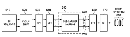
- the transmitter structures and corresponding CQI RS spectrums with CDM and FDM are shown in FIG. 5 and FIG. 6 , respectively.
- a cyclic shift (including a zero cyclic shift) may be subsequently applied 520 .
- the cyclic shift may be prior to the Discrete Frequency Transform (DFT) operation 530 (as shown in FIG. 5 ) or after the Inverse Fast Fourier Transform (IFFT) operation 550 (the modification should be obvious as it involves just moving the corresponding block after the IFFT one).
- DFT Discrete Frequency Transform
- IFFT Inverse Fast Fourier Transform
- the time domain signal is converted to a frequency domain one through the application of a DFT operation 530 as it is known in the art.
- a pulse shaping filter may also be applied at the DFT output (not shown).
- the sub-carrier mapping operation 540 simply places the transmitted sub-carriers into the selected frequency band (RB) and is followed by the IFFT operation 550 and the Cyclic Prefix (CP) insertion 560 .
- the reverse functions are performed at the receiver.
- the spectrum occupancy 570 is continuous.
- the main difference between the transmitter structure in FIG. 6 and the one in FIG. 5 is that in the former the ZC sequence 610 (after the cyclic shift is applied 620 ) is repeated in time by a repetition factor (RPF) 630 . Repetition in time produces in frequency a comb signal spectrum.
- the number of empty sub-carriers between two combs is equal to RPF minus one. Therefore, for RPF of 3, there will be two empty sub-carriers between two consecutive combs. If the CQI RS transmitted by all UEs occupies the same BW, no multiplexing of different BWs is necessary, and the transmitter structure in FIG.
- the comb spectrum may be generated directly in the frequency domain 650 and the cyclic shift may be applied after the IFFT 660 .
- CQI RS from multiple UEs occupy more than one scheduling BWs the multiplexing of orthogonal CQI RS is assumed to be achieved through a hybrid of CDM and FDM.
- CQI RS multiplexing through CDM is achieved through cyclic shifts of the same ZC sequence.
- Multiplexing of CQI RS through FDM is achieved by having the CQI RS occupy different combs of the spectrum.
- UE transmitters as in FIG. 6 can be used to multiplex a number of orthogonal CQI RS equal to the number of cyclic shifts (for the same ZC sequence) providing immunity from the channel delay spread experienced from each CQI RS transmitted by UEs (CDM component).
- CQI RS By providing a comb spectrum for the resulting CQI RS, other CQI RS can be transmitted in the unoccupied part of the spectrum (FDM component).
- the CQI RS occupying different parts of the spectrum may or may not use the same ZC sequence and may or may not occupy the same scheduling BW.
- the serving Node B There is another need for the serving Node B to signal to the UEs parameters required for multiplexing the CQI (sounding) reference signals from a plurality of UEs over the same transmission bandwidth.
- embodiments of the invention provide a signaling method and system for multiplexing reference signals from multiple user equipments (UEs) for channel quality indication (CQI), transmission power control, and transmission timing adjustments, in the uplink of communication systems.
- UEs user equipments
- CQI channel quality indication
- Embodiments of the invention also describe the signaling associated with the multiplexing and co-ordination of the transmission of CQI reference signals from multiple UEs.
- One embodiment of the invention describes the signaling associated with the selection of the sequence used to generate the CQI reference signal from transmitting UEs.
- inventions describe the signaling associated in order to orthogonally multiplex CQI reference signal transmission from a plurality of UEs over the time, frequency, and code domains by correspondingly specifying the transmission period, transmission frequency sub-carrier (or comb), and cyclic shift of the CQI reference signals.
- Yet another embodiment of the invention describes the signaling associated with setting the nominal power of the CQI reference signal transmitted by each respective UE so that a desired reception quality is achieved for the CQI reference signal without unnecessarily increasing the associated interference.
- FIG. 1 is a diagram illustrative of an exemplary communication sub-frame
- FIG. 2 is a diagram illustrative of an exemplary placement of a CQI (or sounding) RS in transmission blocks of communication sub-frames;
- FIG. 3 is a diagram illustrative of an exemplary allocation of Zadoff-Chu based sequences used for CQI RS generation in adjacent Node Bs;
- FIG. 4 is a diagram illustrative of the application of cyclic shifts on the Zadoff-Chu based sequence used for CQI RS generation in order to orthogonally multiplex CQI RS transmission from multiple user equipments in the code domain;
- FIG. 5 is a diagram illustrative of an exemplary generation of CQI RS resulting to continuous spectrum
- FIG. 6 is a diagram illustrative of an exemplary generation of CQI RS resulting to comb spectrum
- FIG. 7 is a diagram showing an allocation of cyclic shifts for the CQI RS from multiple UEs
- FIG. 8 is a diagram showing a first method for orthogonally multiplexing CQI RS transmission from multiple user equipments in the frequency domain;
- FIG. 9 is a diagram showing a second method for orthogonally multiplexing CQI RS transmission from multiple user equipments in the frequency domain.
- FIG. 10 is a diagram showing a third method for orthogonally multiplexing CQI RS transmission from multiple user equipments in the frequency domain.
- the UL CQI RS transmission should be optimized to most efficiently utilize the UL BW while minimizing and simplifying the associated DL control signaling and enabling transmission from a large number of UEs, depending on the operating BW.
- One embodiment of the invention is the periodic CQI RS transmission from UEs having UL transmissions.
- the period of the CQI RS transmission is configured by the Node B through explicit signaling to a UE and can be different among UEs.
- a UE With periodic CQI RS transmission, a UE is given a set of CQI RS parameters to use at specific periodic time instances (CQI RS LBs).
- the Node B configures the CQI RS transmission rate and BW based on the data scheduling type (distributed, localized, persistent), the frequency selectivity of the channel, and the received SINR. These are determined after the random access channel (RACH) conveying a communication request from a UE is received at the Node B.
- RACH random access channel
- the Node B can determine the path loss, the Doppler shift, and the delay spread.
- the CQI RS transmission rate can be relatively low (e.g. every 10 msec).
- the CQI RS may use all or a part of the total BW, depending on the UE SINR conditions, and its transmission rate should be high (for example, every 4 msec).
- the CQI RS may be arranged shortly prior to the scheduling assignment.
- both the CQI RS transmission BW and rate can be low. The opposite apply for frequency selective channels.
- the assignment of the CQI RS parameters to a UE are communicated by the Node B through signaling the Node B transmits to a UE after the RACH reception by the Node B.
- This signaling may be through the RACH response message to the UE, through the control channel, or through higher layer signaling using the data channel.
- the Node B may re-configure the CQI RS parameters either through the control channel or through higher layer signaling using the data channel.
- re-configuration may also occur as a result of changing overall system conditions such as the number of UEs that need to transmit a CQI RS.
- the CQI RS configuration parameters are identified in the remaining of this invention.
- the number of UEs that need to have CQI RS transmission can be as large as 200/400 UEs per cell for a 5/10 MHz operating BW.
- the CQI RS transmitted by multiple UEs over the same scheduling BW should be orthogonal. Otherwise, the CQI RS interference will create CQI and timing estimation errors particularly in conjunction with “near-far” effects especially if only slow power control is used and if corresponding slow power control errors are considered.
- CQI RS orthogonality should not be limited only to one cell but instead it should also be at the intra-Node B level, implying an increase in the number of orthogonal CQI RS by at least a factor of 3 (for 3 adjacent cells of a Node B).
- the total maximum of orthogonal CQI RS is about 1200 (2400) without (with) SU-MIMO or Tx diversity.
- Orthogonal CQI RS with CDM/FDM can be achieved by combining the two options.
- CDM orthogonal CQI RS are obtained by applying cyclic shifts to the ZC sequence.
- a maximum of 12 cyclic shifts with fixed increments of 5.5 ⁇ sec can be obtained to statically protect against a large delay spread (such as for the Typical Urban (TU) channel) while accommodating for a typically large timing error of 0.5 ⁇ sec.
- orthogonal CQI RS are obtained using the repetition factor (RPF).
- RPF repetition factor
- the maximum RPF can be 12 which for a sub-carrier spacing of 15 KHz implies a CQI RS sub-carrier every 180 KHz.
- RPF of 12 the number of ZC sequences for the smaller scheduling BWs (1.25 MHz) becomes excessively small.
- CQI RS from different UEs may also be transmitted at different time instances, thereby also introducing the time dimension for orthogonal CQI RS multiplexing for UEs having the same serving Node B.
- Orthogonal CQI RS can also be achieved with pure FDMA by limiting the scheduling BW.
- the number of orthogonal RS that can be obtained for a scheduling BW of 1.25 MHz is 8 times as large as the corresponding one for a scheduling BW of 10 MHz.
- limiting the scheduling BW leads to throughput losses for UEs in good SINR conditions.
- Orthogonal CQI RS can also be achieved through pure TDMA by increasing the CQI RS LB rate. However, 1 LB for CQI RS every 2 milliseconds (msec) creates a corresponding overhead of about 4.25% and increasing the CQI RS LB rate proportionally increases the overhead and decreases throughput.
- the options of FDMA and TDMA to increase the number of orthogonal CQI RS should be used only when all other alternatives have been exhausted.
- the rate of CQI RS LBs may be increased (for example, from every 2 msec to every 1 msec) to provide orthogonal COI RS gains through TDMA or the maximum scheduling BW may be decreased to provide orthogonal CQI RS gains through FDMA.
- the previous percentage for UEs with localized scheduling was obtained under favorable assumptions, it may be reduced by a factor of 2 if SU-MIMO or selection antenna diversity is applied. It will be reduced by another factor of 2 if the CQI LB RS is every 2 msec to reduce overhead. Also, it will be reduced by another factor of 2 if the CQI RS transmission period is every 2 msec instead of 4 msec to optimize throughput for somewhat larger UE velocities than the smallest possible ones or enable some CQI averaging to improve scheduling accuracy. In any case, in order to meet requirements for the number of orthogonal CQI RS, the previous considered measures result in throughput reductions.
- the conventional approach in assigning the cyclic shift value of the ZC sequence to UEs is to have a fixed value, regardless of the UE delay spread, that is selected to accommodate a typically large delay spread (for example, 5 ⁇ sec for the TU channel).
- UEs experience various delay spreads and the cyclic shift can be adjusted accordingly to increase the number of orthogonal CQI RS that are simultaneously multiplexed over the same BW.
- FIG. 7 shows an example for the allocation of cyclic shifts, assuming SB CQI RS to limit the FIG. 7 size (this embodiment applies regardless of CQI RS transmission in SBs or LBs).
- the cyclic shift allocated to the m th UE is equal to the sum of the largest (estimated at the Node B) timing uncertainties and delay spreads of the previous m ⁇ 1 UEs.
- UE#1 is allocated the original ZC sequence with zero cyclic shift.
- UE#2 is allocated a cyclic shift equal to the timing uncertainty+delay spread of the first UE.
- UE#3 is allocated a cyclic shift equal to the timing uncertainty+delay spread of the first and second UEs, and so on.
- a cyclic shift of T 0 ⁇ sec means a cyclic shift of the ZC sequence by ceil(L* T 0 /T ) samples.
- the exact cyclic shift value also depends on the ZC sequence length. If the CQI RS sub-carrier spacing is 15 KHz, then for RPF of 3 or 4 the ZC sequence length is respectively 25 or 19 (rounded) samples. Since the LB duration is 66.67 ⁇ sec, a cyclic shift of the ZC sequence by 2 samples is equivalent to 5.33 ⁇ sec and 7.02 ⁇ sec, respectively for RPF 3 or 4. Therefore, while an RPF of 3 can be combined with 12 cyclic shifts, an RPF of 4 can only provide 9 cyclic shifts while maintaining orthogonality for the TU channel. In that sense, an RPF of 3 is preferable to an RPF of 4.
- the CQI RS sub-carrier spacing is 7.5 KHz (as previously described), the length of the ZC sequence also doubles. Then, the analysis above applies but for RPF of 6 or 8 and, for the same reasons as before, an RPF of 6 is preferable.
- the cyclic shift granularity is 2.66 ⁇ sec (one ZC sample), capturing the direct path, Ricean, the ITU channels of Pedestrian A and Vehicular A, and a maximum of 24 cyclic shifts are possible.
- the number of cyclic shifts for orthogonal CQI RS can be increased by a factor of about 1.5 by applying the cyclic shift as required by the delay spread and timing error each UE experiences and not by always assigning the maximum cyclic shift regardless of the UE's need.
- cyclic shift being UE specific and ease UE multiplexing
- a small cyclic shift value can be used in environments with low channel delay spread, such as indoor or urban environments or micro-cells
- a large cyclic shift value can be used in environments with large channel delay spread, such as sub-urban environments or macro-cells.
- the cyclic shift value is UE-common but Node B or cell-specific and can be communicated to the UEs for example through a broadcast channel.
- FIG. 8 shows an exemplary partition of 5 MHz operating BW during the CQI RS transmission instance N 840 into 3 scheduling BWs of 1.25 MHz 810 , 2.5 MHz 820 , and 5 MHz 830 which is achieved with RPF of 3.
- the same concept can be extended in a straightforward manner to 10 MHz operating BW and scheduling BWs of 1.25 MHz, 5 MHz, and 10 MHz.
- the number of orthogonal CQI RS is specified by the number of possible cyclic shifts which depends on whether the maximum cyclic shift is always assigned to all UEs regardless of the respective delay spreads or if the cyclic shift assigned to a UE is specified according to the UE's need as previously described in the corresponding embodiment of the invention.
- the CQI RS may hop across scheduling BWs during successive CQI RS transmission instances especially for the small scheduling BWs. This will provide scheduling gains for low speed UEs, some frequency selectivity for “flat” channels and, for pseudo-random hopping patterns across scheduling BWs, interference randomization. It will also enable the Node B to obtain a CQI estimate over the entire operating BW which can be used in applying CQI-based transmission power control on DL signaling, such as control signaling, especially if the UE has only UL data transmission (and no DL data reception, other than control signaling, in which case the UE may not report the DL CQI to the Node B).
- DL signaling such as control signaling
- Interference randomization can also be achieved by switching combs between successive CQI RS transmission periods.
- the 1.25 MHz CQI RS may use the combs allocated to the 2.5 MHz or 5 MHz ones during a previous CQI RS LB instance and vice versa.
- FIG. 9 shows an exemplary application of the previous aspects where during the transmission instance N+1 940 , the 1.25 MHz CQI RS 950 are cyclically rotated and the combs for the 5/2.5/1.25 MHz CQI RS ( 970 / 960 / 950 ) occupy the combs of the 2.5/1.25/5 MHz CQI RS during the previous CQI RS LB (transmission instance N 840 in FIG. 8 ).
- An alternative embodiment to having the CQI RS comb hop between successive CQI RS LBs is to have a predetermined comb for the CQI RS of a given BW.
- the CQI RS with 1.25 BW is always placed in the first comb
- the CQI RS with 2.5 MHz BW is always placed in the second comb
- the advantage of the latter approach is that CQI RS interference may often be from CQI RS having the same BW and therefore the low cross-correlation properties of the ZC sequences can be exploited.
- the CQI RS can complement the DM RS for channel estimation and the DM RS can complement the CQI RS for CQI estimation in the RBs the DM RS is transmitted.
- the UEs transmitting a CQI RS need not be the same between consecutive CQI RS LBs.
- a UE in a particular scheduling BW may have a CQI RS transmission period of 4 msec and transmit during the odd CQI RS LBs while another UE with the same scheduling BW and CQI RS transmission period may transmit its CQI RS during even CQI RS LBs.
- UEs with different CQI RS transmission periods can be orthogonally multiplexed in the time domain.
- the parameters regarding the CQI RS transmission should be configurable for each UE and updated based on decisions made at the Node B which is aware of all current assignments to the UEs transmitting UL CQI RS.
- the CQI RS parameters for a reference UE include:
- the ZC sequence may not have to be signaled if a unique one is used in every cell. In that case, the ZC sequence may be mapped to the cell identity and be implicitly known to the UE after it acquires the cell identity during the synchronization process.
- the BW number should be specified in case there is more than one.
- the assigned BW may be static or have a predetermined time pattern such as a cyclical pattern among the consecutive CQI RS transmission periods (for example, FIG. 8 for CQI RS transmission period N and FIG. 9 for CQI transmission period N+1).
- a UE with initial assignment, to the second 1.25 MHz BW may transmit the CQI RS in the third, fourth, and first 1.25 MHz BWs in the next first, second and third CQI RS transmission periods, respectively, before it repeats that pattern. Therefore, in the exemplary cases of FIG. 8 and FIG. 9 , the control signaling from the Node B to a UE with 1.25 MHz CQI RS BW should include 2 bits to specify one of the four possible CQI RS BWs.
- the previous CQI RS hopping pattern may be a pseudo-random one that repeats over a predetermined time period such as for example a frame comprising of 10 sub-frames (a sub-frame structure is shown in FIG. 1 ). It is possible to avoid explicit signaling of this pseudo-random pattern by mapping it to the cell identity. Then, the UE may derive the CQI; RS BW to use in CQI RS LBs, from the initial assignment, the pseudo-random hopping pattern, and the frame timing (sub-frame number) which, like the cell identity, is acquired during synchronization. The UE implicitly determines the number of possible CQI RS BWs based on its assigned CQI RS BW and the operating BW which is also determined by the UE during the synchronization process.
- the RPF of the ZC sequence is not signaled if it is predetermined and unique. For example, in FIG. 8 , since 3 possible combs exist, it may be predetermined that the 1.25 MHz BW uses the first comb, the 2.5 MHz BW uses the second comb, and the 5 MHz BW uses the third comb. However, in case there are multiple combs for each CQI RS in a scheduling BW, the comb number should be signaled. An exemplary case is shown in FIG.
- the comb assignment may be static for the entire duration of CQI RS transmission, it may have a cyclical pattern (alternating among the possible combs during CQI RS transmission periods in a sequential fashion), or it may have a pseudo-random pattern which may be derived from the cell identity and the sub-frame number or specified in the same manner as for the CQI RS transmission BW.
- different combs may be used for different scheduling BWs as shown in FIG. 9 .
- a combined hopping pattern, whether pseudo-random or predetermined, between the CQI RS transmission BW and the comb used for the CQI RS transmission may also be used to maximize interference randomization.
- the CQI RS transmission period is specified to the UE through Node B signaling. It conveys the period of the CQI RS transmission, such as for example every 4 UL sub-frames, and possibly the sub-frame of the first transmission (for example, the second sub-frame of a frame comprising of ten sub-frames) if multiple such sub-frames exist (for example, the first sub-frame may have been another option).
- the UE transmits the CQI at the second, sixth and tenth sub-frame of a frame comprising of ten sub-frames. As all other parameters, it can be reconfigured through additional signaling and no other issues exist.
- the cyclic shift of the ZC sequence should be signaled by the Node B to the UE.
- the cyclic shift value may be a fixed one corresponding to orthogonality protection from a large delay spread the UE may experience.
- the Node B should specify the cyclic shift based on the delay spread estimate, and possibly a timing error estimate, for the reference UE.
- the assigned cyclic shift value to a UE is the cumulative one of previous cyclic shift values assigned to other UEs for the same ZC sequence, the same CQI RS transmission BW, and the same comb (sub-carrier) in the transmission BW.
- the CQI RS uses a ZC sequence which has low PAPR/CM and the CQI RS uses lower modulation order than possible for the data which also leads to lower PAPR/CM
- the CQI RS transmission power can be increased relative to the data (regardless of whether a simultaneous data transmission exists or not). For UEs in poor SINR conditions, this will result to a better CQI estimate. For UEs in good SINR conditions, a good CQI estimate may be easily available in which case the CQI RS may be transmitted with reduced power relative to the data.
- the Node B may take overall interference considerations into account when adjusting the CQI RS transmission power which is signaled to the UE.
- explicit signaling of the CQI RS transmission power may not be performed and instead a UE can transmit the CQI RS with a power offset relative to the data transmission that is predetermined based on the scheduling BW.
- UEs with small scheduling BWs may transmit the CQI RS with larger power than UEs with large scheduling BW in order to improve the CQI estimation.
- the Node B may configure the CQI RS LB period and the size of CQI RS transmission BWs as system parameters change. For example, as the system load increases, the CQI RS LB period may increase (for example, from every 4 msec to every 2 msec). Also, if most UEs are in poor SINR conditions, the CQI RS transmission for the largest scheduling BW (5 MHz in the example of FIG. 2 ) may be replaced with multiple CQI RS transmissions of correspondingly smaller scheduling BWs. Nevertheless, these modifications by the Node B need not be signaled to the UEs and can be transparent.
- multiple antennas of a singe UE can be treated as different UEs, for the purpose of allocating reference signals. All herein described designs extend in a straightforward manner to the case of multi-antenna transmission.
Abstract
Description
In the above formula, L is the length of the CAZAC sequence, n is the index of a particular element of the sequence n={0, 1, 2 . . . , L−1}, and finally, k is the index of the sequence itself. For a given length L, there are L−1 distinct sequences, provided that L is prime. Therefore, the entire family of ZC sequences is defined as k ranges in {1, 2 . . . , L−1}. For ZC sequences of prime length L, the number of ZC sequences is L−1. Therefore, the larger the ZC length, the larger the number of such sequences, and the possible/easier the cell planning for allocating different ZC sequences to adjacent Node Bs for use by the DM RS.
- a) RPF=3 and 1 out of 3 combs are assigned to 10 MHz CQI RS.
- b) UEs with localized scheduling transmit CQI RS every 4 msec.
Then, for CQI RS LB every 1 msec (8.5% overhead for a fully loaded system) and 12 cyclic shifts, the number of orthogonal CQI RS per 4 msec is 48. As previously mentioned, without considering SU-MIMO or selection antenna diversity, the required number of orthogonal CQI RS is 1200. Assuming that for localized scheduling, the CQI RS transmission rate is 3× that for distributed/persistent scheduling (4 msec versus 12 msec), even if only 1/10 of UEs use 10 MHz scheduling BW (and the remaining use smaller scheduling BWs), only 10% of UEs can have localized scheduling over 10 MHz.
- a) ZC sequence
- b) transmission BW
- c) CQI RS comb and RPF of the ZC sequence
- d) transmission period
- e) cyclic shift of the ZC sequence
- f) transmission power
Claims (21)
Priority Applications (2)
| Application Number | Priority Date | Filing Date | Title |
|---|---|---|---|
| US11/927,148 US7957759B2 (en) | 2006-12-08 | 2007-10-29 | Wideband reference signal transmission in SC-FDMA communication systems |
| US13/104,862 US9838980B2 (en) | 2006-12-08 | 2011-05-10 | Wideband reference signal transmission in SC-FDMA communication systems |
Applications Claiming Priority (2)
| Application Number | Priority Date | Filing Date | Title |
|---|---|---|---|
| US86925506P | 2006-12-08 | 2006-12-08 | |
| US11/927,148 US7957759B2 (en) | 2006-12-08 | 2007-10-29 | Wideband reference signal transmission in SC-FDMA communication systems |
Related Child Applications (1)
| Application Number | Title | Priority Date | Filing Date |
|---|---|---|---|
| US13/104,862 Division US9838980B2 (en) | 2006-12-08 | 2011-05-10 | Wideband reference signal transmission in SC-FDMA communication systems |
Publications (2)
| Publication Number | Publication Date |
|---|---|
| US20080139237A1 US20080139237A1 (en) | 2008-06-12 |
| US7957759B2 true US7957759B2 (en) | 2011-06-07 |
Family
ID=39498740
Family Applications (2)
| Application Number | Title | Priority Date | Filing Date |
|---|---|---|---|
| US11/927,148 Active 2029-11-09 US7957759B2 (en) | 2006-12-08 | 2007-10-29 | Wideband reference signal transmission in SC-FDMA communication systems |
| US13/104,862 Active 2028-10-15 US9838980B2 (en) | 2006-12-08 | 2011-05-10 | Wideband reference signal transmission in SC-FDMA communication systems |
Family Applications After (1)
| Application Number | Title | Priority Date | Filing Date |
|---|---|---|---|
| US13/104,862 Active 2028-10-15 US9838980B2 (en) | 2006-12-08 | 2011-05-10 | Wideband reference signal transmission in SC-FDMA communication systems |
Country Status (1)
| Country | Link |
|---|---|
| US (2) | US7957759B2 (en) |
Cited By (13)
| Publication number | Priority date | Publication date | Assignee | Title |
|---|---|---|---|---|
| US20100002657A1 (en) * | 2007-03-22 | 2010-01-07 | Koon Hoo Teo | Method and System for Generating Antenna Selection Signals in Wireless Networks |
| US20100039998A1 (en) * | 2006-09-29 | 2010-02-18 | Panasonic Corporation | Sequence allocating method and sequence allocating apparatus |
| US20100069028A1 (en) * | 2007-02-02 | 2010-03-18 | Jin Soo Choi | Antenna switching method and method for transmitting and receiving signals for the same |
| US20100086082A1 (en) * | 2007-04-26 | 2010-04-08 | Panasonic Corporation | Radio communication terminal device, radio communication base station device, and radio communication method |
| US20100309852A1 (en) * | 2008-02-05 | 2010-12-09 | Yingyang Li | Method and apparatus for transmitting srs in lte tdd system |
| US20110013578A1 (en) * | 2008-03-12 | 2011-01-20 | Nippon Telegraph And Telephone Corporation | Wireless communication method, wireless communication system, base station, and terminal station |
| US20110212730A1 (en) * | 2008-11-04 | 2011-09-01 | Huawei Technologies Co., Ltd. | Method in a wireless communication system |
| US20110243191A1 (en) * | 2008-12-10 | 2011-10-06 | Panasonic Corporation | Wireless communication terminal apparatus, wireless communication base station apparatus and signal spreading method |
| US20120147836A1 (en) * | 2007-03-01 | 2012-06-14 | Ntt Docomo, Inc. | Base station apparatus and communication control method |
| US20120327860A1 (en) * | 2008-06-25 | 2012-12-27 | Samsung Electronics Co., Ltd. | Method for transmitting a sounding reference signal in a lte tdd system |
| US9838980B2 (en) | 2006-12-08 | 2017-12-05 | Intel Corporation | Wideband reference signal transmission in SC-FDMA communication systems |
| US10841057B2 (en) * | 2016-08-08 | 2020-11-17 | Futurewei Technologies, Inc. | Systems and methods for UE-specific beam management for high frequency wireless communication |
| US11082185B2 (en) | 2007-07-12 | 2021-08-03 | Microsoft Technology Licensing, Llc | Method of transmitting scheduling request in a wireless communication system |
Families Citing this family (41)
| Publication number | Priority date | Publication date | Assignee | Title |
|---|---|---|---|---|
| CN101433004B (en) * | 2006-04-25 | 2014-05-14 | 日本电气株式会社 | Pilot signal transmitting method and wireless communication apparatus |
| US8295266B2 (en) * | 2006-10-25 | 2012-10-23 | Lg Electronics Inc. | Method for adjusting RACH transmission against frequency offset |
| EP2536089A3 (en) * | 2006-12-22 | 2013-04-10 | Fujitsu Limited | Wireless communication method, base station and user terminal |
| KR100880989B1 (en) * | 2007-01-05 | 2009-02-03 | 삼성전자주식회사 | Method and apparatus for transmitting and receiving control signal while randomizing inter-cell interference in mobile telecommunications system |
| US7792212B2 (en) | 2007-01-05 | 2010-09-07 | Lg Electronics, Inc. | Method for setting cyclic shift considering frequency offset |
| TWI581595B (en) | 2007-01-05 | 2017-05-01 | Lg電子股份有限公司 | Method for setting cyclic shift considering frequency offset |
| US9137075B2 (en) * | 2007-02-23 | 2015-09-15 | Telefonaktiebolaget Lm Ericsson (Publ) | Subcarrier spacing identification |
| JP5078989B2 (en) * | 2007-03-15 | 2012-11-21 | パナソニック株式会社 | Wireless transmission apparatus and wireless transmission method |
| EP1971097B1 (en) | 2007-03-16 | 2014-03-12 | LG Electronics Inc. | Method of generating random access preambles in wireless communication system |
| US9344314B2 (en) | 2007-04-24 | 2016-05-17 | Texas Instruments Incorporated | Computer generated sequences for downlink and uplink signals in wireless communication systems |
| US8086272B2 (en) * | 2007-08-06 | 2011-12-27 | Mitsubishi Electric Research Laboratories, Inc. | Wireless networks incorporating antenna selection based on received sounding reference signals |
| CN101094529B (en) * | 2007-08-10 | 2011-03-02 | 中兴通讯股份有限公司 | Method and device for sorting ZC sequence of random access channel |
| JP5213414B2 (en) * | 2007-10-30 | 2013-06-19 | 株式会社エヌ・ティ・ティ・ドコモ | Mobile communication system, base station apparatus, user apparatus and method |
| US8149929B2 (en) * | 2008-06-17 | 2012-04-03 | Telefonaktiebolaget L M Ericsson (Publ) | Receiver and method for processing radio signals using soft pilot symbols |
| EP3567790B1 (en) | 2008-06-20 | 2023-09-06 | NEC Corporation | Resource allocation method and apparatus |
| JP5068699B2 (en) * | 2008-06-23 | 2012-11-07 | 株式会社エヌ・ティ・ティ・ドコモ | Base station apparatus and method |
| US8218663B2 (en) * | 2008-07-29 | 2012-07-10 | Texas Instruments Incorporated | Reference signal resource allocation for single user MIMO |
| US8665803B2 (en) | 2008-07-31 | 2014-03-04 | Qualcomm Incorporated | Tone selection in communication networks |
| JP5276172B2 (en) | 2008-08-14 | 2013-08-28 | サムスン エレクトロニクス カンパニー リミテッド | Method and apparatus for supporting multiple reference signals in an OFDMA communication system |
| USRE47326E1 (en) | 2008-08-14 | 2019-03-26 | Samsung Electronics Co., Ltd | Method and apparatus for supporting multiple reference signals in OFDMA communication systems |
| KR101581956B1 (en) * | 2008-10-22 | 2016-01-04 | 엘지전자 주식회사 | Method and apparatus of transmitting signal in wireless communication system |
| US8817769B2 (en) * | 2009-01-26 | 2014-08-26 | Qualcomm Incorporated | Power decision pilot for wireless communication |
| CN101808357B (en) * | 2009-02-13 | 2012-11-28 | 中兴通讯股份有限公司 | Signal to interference and noise ratio (SINR) estimating method and device |
| CN101841354B (en) * | 2009-03-17 | 2014-02-12 | 电信科学技术研究院 | Method and device for transmitting downlink measurement pilot frequency |
| PL2409513T3 (en) * | 2009-03-19 | 2015-10-30 | Nec Corp | Improved channel quality indicator method |
| SG175306A1 (en) * | 2009-04-24 | 2011-11-28 | Agency Science Tech & Res | Base stations, cellular communication systems, methods for controlling a base station, and methods for controlling a cellular communication system |
| CN101695191B (en) * | 2009-09-29 | 2014-04-09 | 中兴通讯股份有限公司 | System and method for distributing measurement reference signal resource |
| PT2496005T (en) | 2009-10-30 | 2018-10-19 | Sun Patent Trust | Wireless communication apparatus and reference signal generating method |
| KR20110048405A (en) * | 2009-11-02 | 2011-05-11 | 주식회사 팬택 | Method for mapping and transmission of Demodulation Reference Signal, and Communication User Equipment using the same |
| CN102118867A (en) * | 2009-12-31 | 2011-07-06 | 电信科学技术研究院 | Measurement pilot transmission method and device |
| CN102293043A (en) * | 2010-01-08 | 2011-12-21 | 联发科技股份有限公司 | Resource allocation and signaling method for lte sounding |
| KR101797494B1 (en) * | 2010-02-05 | 2017-11-15 | 엘지전자 주식회사 | Method and apparatus for transmitting a sounding reference signal |
| US9407409B2 (en) * | 2010-02-23 | 2016-08-02 | Qualcomm Incorporated | Channel state information reference signals |
| CN102790972B (en) * | 2011-05-18 | 2015-01-14 | 普天信息技术研究院有限公司 | Method and device for generating aerial signal of resource request channel based on ZC sequence |
| CN103220101B (en) * | 2012-01-19 | 2018-02-16 | 中兴通讯股份有限公司 | The notice of frequency spectrum comb signaling, the sending method of detection reference signal and device |
| CN102959918B (en) * | 2012-08-31 | 2015-02-25 | 华为技术有限公司 | A training sequence generating method, a training sequence generating device, and an optical communication system |
| WO2018068823A1 (en) * | 2016-10-10 | 2018-04-19 | Telefonaktiebolaget Lm Ericsson (Publ) | Common reference signal design for ofdm and dfts-ofdm |
| US10630377B2 (en) * | 2016-11-10 | 2020-04-21 | Cable Laboratories, Inc | Systems and methods for beacon detection infrastructures |
| US10656281B2 (en) | 2016-11-10 | 2020-05-19 | Cable Television Laboratories, Inc. | Systems and methods for interference detection in shared spectrum channels |
| CN109951264B (en) * | 2017-12-20 | 2022-06-24 | 上海诺基亚贝尔股份有限公司 | Method, apparatus and computer readable medium for communication |
| US11956171B2 (en) * | 2021-12-08 | 2024-04-09 | Qualcomm Incorporated | Cyclic shift reporting for a reference signal |
Citations (8)
| Publication number | Priority date | Publication date | Assignee | Title |
|---|---|---|---|---|
| US20080039098A1 (en) * | 2006-08-14 | 2008-02-14 | Texas Instruments Incorporated | Methods and apparatus to schedule uplink transmissions in wireless communication systems |
| US20080051125A1 (en) * | 2006-08-22 | 2008-02-28 | Tarik Muharemovic | Adaptive Selection of Transmission Parameters for Reference Signals |
| US20080075184A1 (en) * | 2006-09-22 | 2008-03-27 | Tarik Muharemovic | Transmission of ACK/NACK Bits and their Embedding in the Reference Signal |
| US20080101306A1 (en) * | 2006-10-27 | 2008-05-01 | Pierre Bertrand | Random Access Design for High Doppler in Wireless Networks |
| US20080214198A1 (en) * | 2007-02-09 | 2008-09-04 | Wanshi Chen | Flexible channel quality indicator reporting |
| US20080318528A1 (en) * | 2007-06-20 | 2008-12-25 | Nokia Corporation | Low par zero auto-correlation zone sequences for code sequence modulation |
| US20080318608A1 (en) * | 2007-06-19 | 2008-12-25 | Nec Corporation | Method and device for assigning reference signal sequences in mobile communications system |
| US20090175159A1 (en) * | 2008-01-04 | 2009-07-09 | Pierre Bertrand | Allocation and Logical to Physical Mapping of Scheduling Request Indicator Channel in Wireless Networks |
Family Cites Families (16)
| Publication number | Priority date | Publication date | Assignee | Title |
|---|---|---|---|---|
| US6891792B1 (en) * | 1999-05-14 | 2005-05-10 | At&T Corp. | Method for estimating time and frequency offset in an OFDM system |
| EP1177646B1 (en) * | 2000-03-10 | 2009-02-25 | Samsung Electronics Co., Ltd. | Method for performing handoff in a wireless communication system |
| US6970716B2 (en) * | 2001-02-22 | 2005-11-29 | Telefonaktiebolaget Lm Ericsson (Publ) | Power control for downlink shared channel in radio access telecommunications network |
| JP3787291B2 (en) * | 2001-08-22 | 2006-06-21 | ペンタックス株式会社 | EMC core support, shield, and heat dissipation structure |
| JP2004080235A (en) * | 2002-08-14 | 2004-03-11 | Nec Corp | Cellular system, mobile station, base station, and transmission power control method used for it, as well as its program |
| KR100547758B1 (en) * | 2003-02-28 | 2006-01-31 | 삼성전자주식회사 | Preamble transmitting and receiving device and method of ultra wideband communication system |
| US7426175B2 (en) * | 2004-03-30 | 2008-09-16 | Motorola, Inc. | Method and apparatus for pilot signal transmission |
| US7418046B2 (en) * | 2004-07-22 | 2008-08-26 | Qualcomm Inc. | Pilot transmission and channel estimation for multiple transmitters |
| CA2575317C (en) * | 2004-07-27 | 2012-12-11 | Zte San Diego, Inc. | Transmission and reception of reference preamble signals in ofdma or ofdm communication systems |
| KR100899749B1 (en) | 2005-01-13 | 2009-05-27 | 삼성전자주식회사 | Method for transmitting and receiving preamble sequences in an orthogonal frequency division multiplexing communication system using multiple input multiple output scheme |
| US8130857B2 (en) * | 2006-01-20 | 2012-03-06 | Qualcomm Incorporated | Method and apparatus for pilot multiplexing in a wireless communication system |
| WO2007087602A2 (en) * | 2006-01-25 | 2007-08-02 | Texas Instruments Incorporated | Method and apparatus for increasing the number of orthogonal signals using block spreading |
| US7848438B2 (en) * | 2006-02-14 | 2010-12-07 | Motorola Mobility, Inc. | Method and apparatus for pilot signal transmission |
| US20080045260A1 (en) * | 2006-08-15 | 2008-02-21 | Tarik Muharemovic | Power Settings for the Sounding Reference signal and the Scheduled Transmission in Multi-Channel Scheduled Systems |
| US8320360B2 (en) | 2006-11-06 | 2012-11-27 | Motorola Mobility Llc | Method and apparatus for fast cell search |
| US7957759B2 (en) | 2006-12-08 | 2011-06-07 | Texas Instruments Incorporated | Wideband reference signal transmission in SC-FDMA communication systems |
-
2007
- 2007-10-29 US US11/927,148 patent/US7957759B2/en active Active
-
2011
- 2011-05-10 US US13/104,862 patent/US9838980B2/en active Active
Patent Citations (8)
| Publication number | Priority date | Publication date | Assignee | Title |
|---|---|---|---|---|
| US20080039098A1 (en) * | 2006-08-14 | 2008-02-14 | Texas Instruments Incorporated | Methods and apparatus to schedule uplink transmissions in wireless communication systems |
| US20080051125A1 (en) * | 2006-08-22 | 2008-02-28 | Tarik Muharemovic | Adaptive Selection of Transmission Parameters for Reference Signals |
| US20080075184A1 (en) * | 2006-09-22 | 2008-03-27 | Tarik Muharemovic | Transmission of ACK/NACK Bits and their Embedding in the Reference Signal |
| US20080101306A1 (en) * | 2006-10-27 | 2008-05-01 | Pierre Bertrand | Random Access Design for High Doppler in Wireless Networks |
| US20080214198A1 (en) * | 2007-02-09 | 2008-09-04 | Wanshi Chen | Flexible channel quality indicator reporting |
| US20080318608A1 (en) * | 2007-06-19 | 2008-12-25 | Nec Corporation | Method and device for assigning reference signal sequences in mobile communications system |
| US20080318528A1 (en) * | 2007-06-20 | 2008-12-25 | Nokia Corporation | Low par zero auto-correlation zone sequences for code sequence modulation |
| US20090175159A1 (en) * | 2008-01-04 | 2009-07-09 | Pierre Bertrand | Allocation and Logical to Physical Mapping of Scheduling Request Indicator Channel in Wireless Networks |
Cited By (52)
| Publication number | Priority date | Publication date | Assignee | Title |
|---|---|---|---|---|
| US9025545B2 (en) | 2006-09-29 | 2015-05-05 | Panasonic Intellectual Property Corporation Of America | Sequence allocating method and sequence allocating apparatus |
| US10687368B2 (en) | 2006-09-29 | 2020-06-16 | Panasonic Corporation | Integrated circuit for controlling selection of random access preamble sequence |
| US8730901B2 (en) | 2006-09-29 | 2014-05-20 | Panasonic Corporation | Sequence allocating method and sequence allocating apparatus |
| US9992798B2 (en) | 2006-09-29 | 2018-06-05 | Panasonic Corporation | Integrated circuit for controlling selection of random access preamble sequence |
| US11039483B2 (en) | 2006-09-29 | 2021-06-15 | Panasonic Corporation | Integrated circuit for controlling selection of random access preamble sequence |
| US11742974B2 (en) | 2006-09-29 | 2023-08-29 | Panasonic Holdings Corporation | Integrated circuit for controlling selection of random access preamble sequence |
| US20100039998A1 (en) * | 2006-09-29 | 2010-02-18 | Panasonic Corporation | Sequence allocating method and sequence allocating apparatus |
| US11470653B2 (en) | 2006-09-29 | 2022-10-11 | Panasonic Holdings Corporation | Integrated circuit for controlling selection of random access preamble sequence |
| US10342049B2 (en) | 2006-09-29 | 2019-07-02 | Panasonic Corporation | Integrated circuit for controlling selection of random access preamble sequence |
| US9246539B2 (en) | 2006-09-29 | 2016-01-26 | Panasonic Intellectual Property Corporation Of America | Integrated circuit for controlling selection of random access preamble sequence |
| US9374129B2 (en) | 2006-09-29 | 2016-06-21 | Panasonic Intellectual Property Corporation Of America | Integrated circuit for controlling selection of random access preamble sequence |
| US8363608B2 (en) * | 2006-09-29 | 2013-01-29 | Panasonic Corporation | Sequence allocating method and sequence allocating apparatus |
| US8750235B2 (en) | 2006-09-29 | 2014-06-10 | Panasonic Corporation | Sequence allocating method and sequence allocating apparatus |
| US9838980B2 (en) | 2006-12-08 | 2017-12-05 | Intel Corporation | Wideband reference signal transmission in SC-FDMA communication systems |
| US8774736B2 (en) * | 2007-02-02 | 2014-07-08 | Lg Electronics Inc. | Antenna switching for data transmission in a communication system using a plurality of transmission antennas |
| US20100069028A1 (en) * | 2007-02-02 | 2010-03-18 | Jin Soo Choi | Antenna switching method and method for transmitting and receiving signals for the same |
| US20120147836A1 (en) * | 2007-03-01 | 2012-06-14 | Ntt Docomo, Inc. | Base station apparatus and communication control method |
| US8223723B2 (en) * | 2007-03-22 | 2012-07-17 | Mitsubishi Electric Research Laboratories, Inc. | Method and system for generating antenna selection signals in wireless networks |
| US20100002657A1 (en) * | 2007-03-22 | 2010-01-07 | Koon Hoo Teo | Method and System for Generating Antenna Selection Signals in Wireless Networks |
| US20100086082A1 (en) * | 2007-04-26 | 2010-04-08 | Panasonic Corporation | Radio communication terminal device, radio communication base station device, and radio communication method |
| US11316640B2 (en) | 2007-07-12 | 2022-04-26 | Microsoft Technology Licensing, Llc | Method of transmitting scheduling request in a wireless communication system |
| US11082185B2 (en) | 2007-07-12 | 2021-08-03 | Microsoft Technology Licensing, Llc | Method of transmitting scheduling request in a wireless communication system |
| US9160508B2 (en) | 2008-02-05 | 2015-10-13 | Samsung Electronics Co., Ltd | Method and apparatus for transmitting SRS in LTE TDD system |
| US9160509B2 (en) | 2008-02-05 | 2015-10-13 | Samsung Electronics Co., Ltd | Method and apparatus for transmitting SRS in LTE TDD system |
| US9160507B2 (en) | 2008-02-05 | 2015-10-13 | Samsung Electronics Co., Ltd. | Method and apparatus for transmitting SRS in LTE TDD system |
| US9160506B2 (en) | 2008-02-05 | 2015-10-13 | Samsung Electronics Co., Ltd. | Method and apparatus for transmitting SRS in LTE TDD system |
| US9160510B2 (en) | 2008-02-05 | 2015-10-13 | Samsung Electronics Co., Ltd | Method and apparatus for transmitting SRS in LTE TDD system |
| US9166757B2 (en) | 2008-02-05 | 2015-10-20 | Samsung Electronics Co., Ltd | Method and apparatus for transmitting SRS in LTE TDD system |
| US9166756B2 (en) | 2008-02-05 | 2015-10-20 | Samsung Electronics Co., Ltd | Method and apparatus for transmitting SRS in LTE TDD system |
| US9160505B2 (en) | 2008-02-05 | 2015-10-13 | Samsung Electronics Co., Ltd. | Method and apparatus for transmitting SRS in LTE TDD system |
| US9025429B2 (en) | 2008-02-05 | 2015-05-05 | Samsung Electronics Co., Ltd. | Method and apparatus for transmitting SRS in LTE TDD system |
| US9413505B2 (en) | 2008-02-05 | 2016-08-09 | Samsung Electronics Co., Ltd | Method and apparatus for transmitting SRS in LTE TDD system |
| US9413504B2 (en) | 2008-02-05 | 2016-08-09 | Samsung Electronics Co., Ltd | Method and apparatus for transmitting SRS in LTE TDD system |
| US20100309852A1 (en) * | 2008-02-05 | 2010-12-09 | Yingyang Li | Method and apparatus for transmitting srs in lte tdd system |
| US8520492B2 (en) * | 2008-02-05 | 2013-08-27 | Samsung Electronics Co., Ltd | Method and apparatus for transmitting SRS in LTE TDD system |
| US8532140B2 (en) * | 2008-03-12 | 2013-09-10 | Nippon Telegraph And Telephone Corporation | Wireless communication method, wireless communication system, base station, and terminal station |
| US20110013578A1 (en) * | 2008-03-12 | 2011-01-20 | Nippon Telegraph And Telephone Corporation | Wireless communication method, wireless communication system, base station, and terminal station |
| US9787447B2 (en) * | 2008-06-25 | 2017-10-10 | Samsung Electronics Co., Ltd. | Method for transmitting a sounding reference signal in a LTE TDD system |
| US10411855B2 (en) | 2008-06-25 | 2019-09-10 | Samsung Electronics Co., Ltd | Method for transmitting a sounding reference signal in an LTE TDD system |
| US20120327860A1 (en) * | 2008-06-25 | 2012-12-27 | Samsung Electronics Co., Ltd. | Method for transmitting a sounding reference signal in a lte tdd system |
| US8634844B2 (en) | 2008-11-04 | 2014-01-21 | Huawei Technologies Co., Ltd. | Method in a wireless communication system |
| US20110212730A1 (en) * | 2008-11-04 | 2011-09-01 | Huawei Technologies Co., Ltd. | Method in a wireless communication system |
| US9055566B2 (en) | 2008-11-04 | 2015-06-09 | Huawei Technologies Co., Ltd. | Method in a wireless communication system |
| US10958305B2 (en) | 2008-12-10 | 2021-03-23 | Sun Patent Trust | Communication terminal and communication method |
| US9831911B2 (en) | 2008-12-10 | 2017-11-28 | Sun Patent Trust | Communication apparatus and communication method |
| US10574291B2 (en) | 2008-12-10 | 2020-02-25 | Sun Patent Trust | Integrated circuit |
| US20110243191A1 (en) * | 2008-12-10 | 2011-10-06 | Panasonic Corporation | Wireless communication terminal apparatus, wireless communication base station apparatus and signal spreading method |
| US11387862B2 (en) | 2008-12-10 | 2022-07-12 | Sun Patent Trust | Base station and communication method |
| US9425916B2 (en) * | 2008-12-10 | 2016-08-23 | Sun Patent Trust | Wireless communication terminal apparatus, wireless communication base station apparatus and signal spreading method |
| US10158398B2 (en) | 2008-12-10 | 2018-12-18 | Sun Patent Trust | Integrated circuit |
| US11799515B2 (en) | 2008-12-10 | 2023-10-24 | Sun Patent Trust | Integrated circuit |
| US10841057B2 (en) * | 2016-08-08 | 2020-11-17 | Futurewei Technologies, Inc. | Systems and methods for UE-specific beam management for high frequency wireless communication |
Also Published As
| Publication number | Publication date |
|---|---|
| US9838980B2 (en) | 2017-12-05 |
| US20080139237A1 (en) | 2008-06-12 |
| US20110212745A1 (en) | 2011-09-01 |
Similar Documents
| Publication | Publication Date | Title |
|---|---|---|
| US7957759B2 (en) | Wideband reference signal transmission in SC-FDMA communication systems | |
| KR101992199B1 (en) | Method for transmitting SRS and terminal for the same | |
| US11139937B2 (en) | Uplink control information transmission method and device | |
| JP7146908B2 (en) | Method for transmitting and receiving SRS and communication device therefor | |
| JP4601637B2 (en) | Mobile station, transmission method, and wireless communication system | |
| EP3253000B1 (en) | Frequency hopping technique for eutra uplink | |
| KR101297458B1 (en) | Method of channel sounding in FDD system | |
| US11539562B2 (en) | Reference signal having variable structure | |
| US8891493B2 (en) | Method and device for assigning reference signal sequences in mobile communications system | |
| KR101036256B1 (en) | User device, base station apparatus, and method | |
| CN102754373B (en) | For the apparatus and method of the feature of enhanced uplink reference signal | |
| JP5074007B2 (en) | User terminal apparatus and base station apparatus | |
| KR101306728B1 (en) | method of allocation resource for uplink control channel | |
| KR20070120437A (en) | Band allocation method and radio communication system | |
| CN102217348B (en) | A method and system for assigning reference signals in a multi-antenna context | |
| JP5856191B2 (en) | Apparatus and method for improving the characteristics of uplink reference signals | |
| Veyseh et al. | Cross-layer channel allocation protocol for OFDMA ad hoc networks | |
| JP5066236B2 (en) | Base station apparatus and reception method | |
| Garcia-Luna-Aceves | Cross-Layer Channel Allocation Protocol for OFDMA Ad Hoc Networks |
Legal Events
| Date | Code | Title | Description |
|---|---|---|---|
| AS | Assignment |
Owner name: TEXAS INSTRUMENTS INCORPORATED, TEXAS Free format text: ASSIGNMENT OF ASSIGNORS INTEREST;ASSIGNOR:PAPASAKELLARIOU, ARIS;REEL/FRAME:020354/0243 Effective date: 20080110 |
|
| STCF | Information on status: patent grant |
Free format text: PATENTED CASE |
|
| FPAY | Fee payment |
Year of fee payment: 4 |
|
| FEPP | Fee payment procedure |
Free format text: PAYOR NUMBER ASSIGNED (ORIGINAL EVENT CODE: ASPN); ENTITY STATUS OF PATENT OWNER: LARGE ENTITY |
|
| AS | Assignment |
Owner name: INTEL CORPORATION, CALIFORNIA Free format text: ASSIGNMENT OF ASSIGNORS INTEREST;ASSIGNOR:TEXAS INSTRUMENTS INCORPORATED;REEL/FRAME:041383/0040 Effective date: 20161223 |
|
| MAFP | Maintenance fee payment |
Free format text: PAYMENT OF MAINTENANCE FEE, 8TH YEAR, LARGE ENTITY (ORIGINAL EVENT CODE: M1552); ENTITY STATUS OF PATENT OWNER: LARGE ENTITY Year of fee payment: 8 |
|
| AS | Assignment |
Owner name: APPLE INC., CALIFORNIA Free format text: ASSIGNMENT OF ASSIGNORS INTEREST;ASSIGNOR:INTEL CORPORATION;REEL/FRAME:052414/0001 Effective date: 20191130 |
|
| MAFP | Maintenance fee payment |
Free format text: PAYMENT OF MAINTENANCE FEE, 12TH YEAR, LARGE ENTITY (ORIGINAL EVENT CODE: M1553); ENTITY STATUS OF PATENT OWNER: LARGE ENTITY Year of fee payment: 12 |