EP2128494B1 - Stufenlos verstellbares Getriebe - Google Patents
Stufenlos verstellbares Getriebe Download PDFInfo
- Publication number
- EP2128494B1 EP2128494B1 EP20080425387 EP08425387A EP2128494B1 EP 2128494 B1 EP2128494 B1 EP 2128494B1 EP 20080425387 EP20080425387 EP 20080425387 EP 08425387 A EP08425387 A EP 08425387A EP 2128494 B1 EP2128494 B1 EP 2128494B1
- Authority
- EP
- European Patent Office
- Prior art keywords
- rotor
- contact
- transmission according
- rolling members
- profile
- Prior art date
- Legal status (The legal status is an assumption and is not a legal conclusion. Google has not performed a legal analysis and makes no representation as to the accuracy of the status listed.)
- Not-in-force
Links
- 230000005540 biological transmission Effects 0.000 title claims description 18
- 238000005096 rolling process Methods 0.000 claims description 27
- 230000033001 locomotion Effects 0.000 claims description 15
- 238000010276 construction Methods 0.000 claims description 5
- 230000003247 decreasing effect Effects 0.000 claims description 2
- 230000009347 mechanical transmission Effects 0.000 claims description 2
- 230000002093 peripheral effect Effects 0.000 claims description 2
- 230000008901 benefit Effects 0.000 description 3
- 230000006835 compression Effects 0.000 description 3
- 238000007906 compression Methods 0.000 description 3
- 230000009471 action Effects 0.000 description 2
- 230000008859 change Effects 0.000 description 2
- 208000018672 Dilatation Diseases 0.000 description 1
- 230000002457 bidirectional effect Effects 0.000 description 1
- 230000008878 coupling Effects 0.000 description 1
- 238000010168 coupling process Methods 0.000 description 1
- 238000005859 coupling reaction Methods 0.000 description 1
- 125000004122 cyclic group Chemical group 0.000 description 1
- 230000001419 dependent effect Effects 0.000 description 1
- 230000000694 effects Effects 0.000 description 1
- 239000012530 fluid Substances 0.000 description 1
- 239000010687 lubricating oil Substances 0.000 description 1
- 238000005461 lubrication Methods 0.000 description 1
- 230000007246 mechanism Effects 0.000 description 1
- 238000011084 recovery Methods 0.000 description 1
- 230000003362 replicative effect Effects 0.000 description 1
- 230000000717 retained effect Effects 0.000 description 1
- 230000002441 reversible effect Effects 0.000 description 1
- 230000001131 transforming effect Effects 0.000 description 1
Images

Classifications
-
- F—MECHANICAL ENGINEERING; LIGHTING; HEATING; WEAPONS; BLASTING
- F16—ENGINEERING ELEMENTS AND UNITS; GENERAL MEASURES FOR PRODUCING AND MAINTAINING EFFECTIVE FUNCTIONING OF MACHINES OR INSTALLATIONS; THERMAL INSULATION IN GENERAL
- F16H—GEARING
- F16H29/00—Gearings for conveying rotary motion with intermittently-driving members, e.g. with freewheel action
- F16H29/12—Gearings for conveying rotary motion with intermittently-driving members, e.g. with freewheel action between rotary driving and driven members
- F16H29/16—Gearings for conveying rotary motion with intermittently-driving members, e.g. with freewheel action between rotary driving and driven members in which the transmission ratio is changed by adjustment of the distance between the axes of the rotary members
-
- F—MECHANICAL ENGINEERING; LIGHTING; HEATING; WEAPONS; BLASTING
- F16—ENGINEERING ELEMENTS AND UNITS; GENERAL MEASURES FOR PRODUCING AND MAINTAINING EFFECTIVE FUNCTIONING OF MACHINES OR INSTALLATIONS; THERMAL INSULATION IN GENERAL
- F16H—GEARING
- F16H37/00—Combinations of mechanical gearings, not provided for in groups F16H1/00 - F16H35/00
- F16H37/02—Combinations of mechanical gearings, not provided for in groups F16H1/00 - F16H35/00 comprising essentially only toothed or friction gearings
- F16H37/06—Combinations of mechanical gearings, not provided for in groups F16H1/00 - F16H35/00 comprising essentially only toothed or friction gearings with a plurality of driving or driven shafts; with arrangements for dividing torque between two or more intermediate shafts
- F16H37/08—Combinations of mechanical gearings, not provided for in groups F16H1/00 - F16H35/00 comprising essentially only toothed or friction gearings with a plurality of driving or driven shafts; with arrangements for dividing torque between two or more intermediate shafts with differential gearing
- F16H37/0833—Combinations of mechanical gearings, not provided for in groups F16H1/00 - F16H35/00 comprising essentially only toothed or friction gearings with a plurality of driving or driven shafts; with arrangements for dividing torque between two or more intermediate shafts with differential gearing with arrangements for dividing torque between two or more intermediate shafts, i.e. with two or more internal power paths
- F16H37/084—Combinations of mechanical gearings, not provided for in groups F16H1/00 - F16H35/00 comprising essentially only toothed or friction gearings with a plurality of driving or driven shafts; with arrangements for dividing torque between two or more intermediate shafts with differential gearing with arrangements for dividing torque between two or more intermediate shafts, i.e. with two or more internal power paths at least one power path being a continuously variable transmission, i.e. CVT
- F16H37/086—CVT using two coaxial friction members cooperating with at least one intermediate friction member
Definitions
- the invention refers to a continuously variable transmission-ratio (briefly TR) mechanical transmission (briefly CVT).
- EP 1 688 645 is described a known CVT having rollers along a circumference, see its fig. 2 .
- the inner rotor is provided with a superficial inclined-plane toothing. Altogether the rotors and the rollers constitute a free wheel.
- the TR between the rotors is higher the greater the length of the inclined planes provided on the inner rotor (namely, the longer the travel of the roller on them). Also, the total torque transferred to the outer rotor is the "averaged" sum of the impulsive contributions of each roller when it is in the phase of thrust/grip.
- Another aspect is the cyclic variation of the contact angle between a roller with the relative inclined plane on the inner rotor and the same roller with the outer rotor.
- the containment angle i.e. the instantaneous angle between the surfaces of a roller and the rotor on which it rolls, varies dynamically
- the transmission is to be designed such that it always meets the numerical relations described above, i.e. in the worst case.
- US 3 987 682 dicloses CVT according to the preamble of claim 1 and describes a CVT employing outer sprags or cams to drive an inner, driven output shaft.
- the sprags has a first contact profile in contact with the output shaft, and a second, opposite profile which cooperates with a spring belt urging the sprags in contact with the inner rotor.
- the object of the present invention is to devise an alternative CVT.
- the devised solution is recited in Claim 1.Further preferred embodiments are defined in the dependent claims.
- the containment angle can be kept substantially constant or at a desired value for the whole duration of the rolling in the thrust phase (called active phase) of each rolling member.
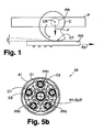
- the profile of the cam C is in contact at point CT with a horizontal plane PO, and the profile of the cam C is such to assure that the contact angle ⁇ (defined as the angle between the plane PO and the tangent to the same profile of the cam C at the contact point CT) be (preferably) substantially constant.
- the cam C is produced to have a profile such as to keep constant its contact angle with the plane PO, or more generally with a rotating part to which mechanical power and rotary motion is to be transferred. This way the optimal friction between cams and rotors is guaranteed, the friction being determined by the pressure on the same cam C and by the mutual friction coefficient.
- the constancy of the contact angle is however only a preferred embodiment. It might be useful to carry out cams which offer, during their rolling, a contact angle with a slightly increasing or decreasing pattern/trend. This to obtain a desired distribution of the thrust pressures on the (inner and/or outer) rotors.
- a cunning of this type has the advantage of designing the specific pressures that every part exerts, thereby increasing the efficiency thereof.
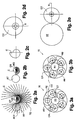
- Figures 2a-2c show a preferred geometrical construction for the cam C and the coupling by contact with a rotor (or shaft) RT. Given the constructional analogy, some numerals used in fig. 1 are retained.
- the cam C has an evolvent profile, preferably a logarithmic spiral profile. It is about a geometrical construction wherein the generation of the cam profile is carried out by maintaining a proportionality between the angular increment of the profile and the pitch of moving away from the rotation center CR.
- cams C can be exploited, and not only about 180°, replicating specularly the contact profile thereof (constructed for instance as in figures 2a-2c ) on the opposite side, see cams CD in figures 2d-2e .
- cams CD in figures 2d-2e .
- Figures 3a-3b show an application scheme of the concept just set out, repeated for five cams CD along a circumference to constitute a CVT according to the invention indicated by 10.
- the rotor R2 rotatably supports the five cams CD (the cams CD are pivoted on the rotor R2 by rolling bearings), all with their profile in contact with the rotor R1. It should be noted that the overall structure is that of a free wheel.
- each of the cams CD of the CVT 10 in turn pushes the rotor R1, rotating about it for roughly 180° of "satellite” rotation and at the same time rotating on itself, again for roughly 180° (non-slipping condition).
- the two rotary motions combined vectorially determine a TR > 1.
- the cams employed are indeed double-profile cams.
- the specular (or mirror) cam profile which does not contact the rotor R1 is used to always ensure the contact between each cam CD and the rotor R1.
- a containment ring AN is mounted concentrically to the rotor R1, (see figures 3a-3b ), such that it holds within it all the cams CD.
- the cams CD in fact, remain in direct contact with the ring AN without ever coming off. Owing to the geometry of the cams CD, for every contact point CT thereof with the rotor R1 there is another one on the ring AN, so the cams always move between the rotor R1 and the ring AN with contact on two sides, without leaving clearance.
- the ring AN is subject to the same thrusts imposed on the rotor R1.
- the system geometry is such that an angular velocity greater than that of the rotor R1 is imparted to the ring AN by the rotor R2.
- a solution is to mount the ring AN on bearings and let it rotate idle, or make it integral with the rotor R1, as described below.
- the structure of the CVT 10 (like for the others in the following) is bidirectional and reversible: the rotary motion can be transferred from the rotor R2 to the rotor R1 or vice versa, on condition that the cams be properly oriented.
- the resulting TR is always the same.
- Figures 4a-c show a possible embodiment 20 for a CVT.
- the cam-carrying rotor R2 described above in fig. 3a, 3b is constituted by two rings (or discs) A1, A2 mounted on the exterior and offsettably with respect both to an inner rotor/shaft R1-IN, which brings mechanical power to the input of the CVT 20, and to an independent rotor R1-OUT, coaxial to the rotor R1-IN and which brings mechanical power to the output of the CVT 20.
- the two discs A1, A2 are connected and made integral by pins PR1, on which two groups of cams are mounted with bearings (C1, C2 indicate respectively the cams for each group).
- the cams of each group are arranged with polar symmetry on the discs A1, A2 (like in fig. 3a ), and they are implemented as already described above.
- the pins PR1 act as rotation fulcrum for the cams C1, C2. Note that on every pin PR1 there are superimposed one cam C1 and one cam C2, with their tip pointing in opposite directions.
- the cams C1 of the first group are in contact on one side with the rotor R1-IN, on the other side - on the outside - with a containment ring AN1, according to the scheme and principles of fig. 3a, 3b .
- the cams C2 of the second group are in contact with the rotor R1-OUT.
- the second group of cams C2, too, is in contact, on the outside, with a containment ring of its own, called AN2 (see fig. 4b ).
- AN2 containment ring of its own
- the CVT 20 is formed by two equal cascaded stages (one following the other): the first stage is formed by the rotor R1-IN and the first group of cams C1, the second stage is formed by the second group of cams C2 and the rotor R1-OUT.
- the two equal stages are cinematically connected in cascade connection by a common member, i.e. the cam-carrying rotor R2.
- the rotor R1-IN When the discs A1, A2 are not concentric to the rotors R1-IN and R1-OUT, i.e. offset, the rotor R1-IN while rotating moves the disc A1 through the first group of cams C1 with a TR > 1.
- the disc A2, integral with the disc A1 then transfers with the same TR the rotary motion to the rotor R1-OUT, through the second group of cams C2.
- the TR between the rotors R1-IN and R1-OUT is the product of that of the two single stages, and for this reason much higher. Nonetheless, the compact structure of the CVT 20 may be appreciated.
- cams C1, C2 were all directed in the same way, there would be an interruption in the motion transfer for one of the two groups of cams, since such a stage would operate like an idle free wheel.
- Each group of cams is therefore mounted on a respective face of the disc 32a.
- the disc 32a is rotatably supported by a circular ring 36a which, through a fork 37a and mechanisms not shown, allows to move eccentrically the disc 32a with respect of an inner central shaft 38 (common to the symmetric parts of the CVT 30), which is integral in the middle with a double containment cage 40.
- the shaft 38 is coaxially inserted in the central hole of the disc 32a.
- the cage 40 shows two opposite annular seats SOa, SOb, which are separated by a wall 44.
- a group of cams COa of the disc 32a are housed with peripheral contact inside the seats SOa.
- the other group of cams COa is housed in a cover bell 42a of a tubular hollow rotor 41 a.
- the rotor 41 a is rotatably arranged about the shaft 38, the inside of the bell 42a housing, once mounted, said first group of cams CDa.
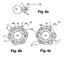
- Fig. 6a shows a variant CS of a cam rolling member, whose peculiar characteristic is to have two profiles (preferably evolvent profiles) F, B (forward and back) arranged on two parallel planes.
- the member CS may be produced with two integral and facing cams, one for each profile F, B.
- the advantage of the cam CS is to exploit for more than 180° of rotation its own contact profile during the thrust on a rotor (indicated by RT in fig. 6a ).
- the consequence is a greater TR, because the motion imparted to the rotor RT is, as already said, the sum of two rotation motions of the rolling member CS, of which one is the rotation motion about its own axis CR. If the latter motion is lengthened, for every "satellite" revolution of a rolling member CS about the rotor RT, said rolling member has made it rotate more.
- Figures 6b, 6c show an application scheme of the concept just illustrated, repeated for six cams CS along a circumference to constitute a CVT according to the invention denoted by 40.
- the rotor R1 rotatably supports the cams CS.
- the cams CS have the profile F in contact with the rotor R1 and the profile B in contact with an external ring AN, fixed or not. Again, the overall structure is that of a free wheel.
Landscapes
- Engineering & Computer Science (AREA)
- General Engineering & Computer Science (AREA)
- Mechanical Engineering (AREA)
- Friction Gearing (AREA)
Claims (14)
- Mechanisches Getriebe (10; 20; 30; 40) mit stufenlos veränderlicher Übersetzung, bestehend aus- einem Antriebsrotor (R2; R1-IN; 41a), und- einem vom Antriebsrotor angetriebenen Abtriebsrotor (R1; R1-OUT; 38),
wobei beide Rotoren ineinander angeordnet sind und derart montiert, dass sie außer Achse versetzt werden können, damit ihre relative Exzentrizität geändert werden kann;- mehreren rollenden Bauteilen (C; CD; C1, C2; CS), die zwischen den Rotoren angeordnet sind und ein ERSTES Kontaktprofil haben, entlang dem sie auf einem Rotor rollen können, um diesem eine Drehbewegung mit erhöhter Winkelgeschwindigkeit, in Funktion des Exzentrizitätsgrades zwischen den beiden Rotoren, zu erteilen, wobeidie rollenden Bauteile auf einem Rotor drehbar um eine Rotationsachse (CR) montiert sind und das Kontaktprofil einen geometrischen Aufbau mit einem variablen Abstand von der erwähnten Achse hat, wobei die rollenden Bauteile (CD; CDS) über ein zweites Kontaktprofil verfügen,
dadurch gekennzeichnet, dass es außerdem einen Schließring (AN) umfasst, der um die genannten Bauteile derart montiert ist, dass eines der beiden Profile immer mit ihm in Berührung ist. - Getriebe nach Anspruch 1, bei dem das ERSTE Kontaktprofil eine geometrische Struktur mit einem von der genannten Achse progressiv erhöhenden Abstand aufweist.
- Getriebe nach Anspruch 2, bei dem die rollenden Bauteile derart angeordnet sind, dass sie direkt auf einer Oberfläche eines Rotors rollen können, wobei das ERSTE Kontaktprofil einen derartigen Verlauf, vorzugsweise einen im Wesentlichen logarithmischen Spiralenverlauf hat, dass ein im Wesentlichen konstanter Kontaktwinkel (α) mit der genannten Oberfläche gewährleistet werden kann.
- Getriebe nach Anspruch 2, bei dem die rollenden Bauteile derart angeordnet sind, dass sie direkt auf einer Oberfläche eines Rotors rollen, wobei das ERSTE Kontaktprofil einen derartigen Verlauf hat, dass ein Kontaktwinkel (α) mit genannter Oberfläche bewahrt wird und einen zunehmenden bzw. abnehmenden Verlauf zwischen zwei vorgegebenen Werten hat.
- Getriebe nach Anspruch 1, bei dem beide genannte Kontaktprofile im Wesentlichen gleich sind und spiegelbildlich auf zwei gegenüberliegenden Seiten der rollenden Bauteile gewonnen werden.
- Getriebe nach Anspruch 1, bei dem beide genannte Kontaktprofile (F, B) mit einem bestimmten Abstand auf zwei parallelen Flächen angeordnet sind.
- Getriebe nach Anspruch 6, bei dem beide mit einem bestimmten Abstand angeordnete Kontaktprofile (F, B) mit zwei einteilig ausgebildeten und nebeneinander liegenden Nocken, einer je Profil, realisiert sind.
- Getriebe nach Anspruch 1, bei dem der Schließring (AN) so montiert ist, damit er lose oder fest an einem Rotor drehen kann.
- Getriebe nach einem der vorherigen Ansprüche, bei dem ein Rotor aus zwei koaxialen Halterungsringen (AN1, AN2) besteht, die intern durch strahlensymmetrisch um den anderen Rotor angeordneten Zapfen miteinander verbunden sind, wobei auf jedem Zapfen zwei unabhängig drehbare rollende Bauteile (CS) in entgegengesetzter Richtung montiert sind.
- Getriebe nach einem der vorherigen Ansprüche, bei dem ein Rotor aus einem Halterungsring (32a) besteht, wobei auf jeder Seite des Halterungsrings Zapfen (34a) strahlensymmetrisch um die Drehachse angeordnet sind, wobei auf jedem Zapfen zwei unabhängig drehbare rollende Bauteile (CD) in entgegengesetzter Richtung montiert sind.
- Getriebe nach Anspruch 9 und/oder 10, bestehend aus einem zentralen Rotor (38) an dem genannten Halterungsring bzw. Ringen (AN1, AN2; 32a), mit dem die rollenden Bauteile in Berührung sind, wobei dieser Halterungsring bzw. diese Halterungsringe drehbar auf einem weiteren Außenring (36a) montiert ist/sind, der rechtwinklig zum Zentralrotor mobil ist, damit die Exzentrizität zwischen dem genannten Halterungsring bzw. -Ringen und dem genannten Zentralrotor geändert werden kann.
- Getriebe nach Anspruch 11, bestehend aus einem Rotor (40), der in gleichzeitiger Berührung mit einer ersten und einer zweiten Gruppe von rollenden Bauteilen (CDa, CDb) montiert ist, wobei die zwei Gruppen auf gesonderten Rotoren (32a, 32b) montiert sind und der gemeinsame Rotor dazu dient, die Drehbewegung von der ersten Gruppe aufzunehmen, um diese an die zweite zu übertragen.
- Getriebe nach Anspruch 12, bei dem der genannte gemeinsame Rotor aus einer mit ihm einteiligen runden Struktur mit H-förmigem Querschnitt besteht, die dazu dient, auf den zwei entgegengesetzten Seiten zwei Gruppen von rollenden Bauteilen (CDa, CDb) aufzunehmen, die auf zwei gesonderten Rotoren (32a, 32b) drehbar angelenkt sind.
- Getriebe nach einem der vorherigen Ansprüche 5 bis 13, bei dem ein Rotor (41a) aus einer glockenförmigen Struktur (42a) besteht, die mit dem Außenrand in Berührung mit einem der beiden Kontaktprofilen einer Gruppe von rollenden Bauteilen (CDa) montiert ist, die drehbar auf einem anderen Rotor (32a) angelenkt sind.
Priority Applications (1)
| Application Number | Priority Date | Filing Date | Title |
|---|---|---|---|
| EP20080425387 EP2128494B1 (de) | 2008-05-29 | 2008-05-29 | Stufenlos verstellbares Getriebe |
Applications Claiming Priority (1)
| Application Number | Priority Date | Filing Date | Title |
|---|---|---|---|
| EP20080425387 EP2128494B1 (de) | 2008-05-29 | 2008-05-29 | Stufenlos verstellbares Getriebe |
Publications (2)
| Publication Number | Publication Date |
|---|---|
| EP2128494A1 EP2128494A1 (de) | 2009-12-02 |
| EP2128494B1 true EP2128494B1 (de) | 2012-05-23 |
Family
ID=39838148
Family Applications (1)
| Application Number | Title | Priority Date | Filing Date |
|---|---|---|---|
| EP20080425387 Not-in-force EP2128494B1 (de) | 2008-05-29 | 2008-05-29 | Stufenlos verstellbares Getriebe |
Country Status (1)
| Country | Link |
|---|---|
| EP (1) | EP2128494B1 (de) |
Families Citing this family (3)
| Publication number | Priority date | Publication date | Assignee | Title |
|---|---|---|---|---|
| JP6461969B2 (ja) * | 2013-09-05 | 2019-01-30 | ウーエムエス マシネンバウ ゲーエムベーハーU.M.S.−Maschinenbau GmbH | 無段変速機 |
| DE102016122845A1 (de) * | 2016-11-28 | 2018-05-30 | Tq-Systems Gmbh | Harmonisches Pinring-Getriebe, Drehmomentmessvorrichtung und Freilaufanordnung |
| WO2019166478A1 (de) * | 2018-02-27 | 2019-09-06 | Dieter Gerhard Fahrni | Stufenloses getriebe und verfahren zum betreiben eines stufenlosen getriebes |
Family Cites Families (3)
| Publication number | Priority date | Publication date | Assignee | Title |
|---|---|---|---|---|
| US3987682A (en) * | 1974-07-11 | 1976-10-26 | Cyclecentric Corporation | Variable speed transmission |
| JP2000230610A (ja) * | 1999-02-09 | 2000-08-22 | Kenji Mimura | 無段変速機 |
| ITTV20050018A1 (it) | 2005-02-03 | 2006-08-04 | Adriano Girotto | Trasmissione a rapporto di trasmissione variabile linearmente. |
-
2008
- 2008-05-29 EP EP20080425387 patent/EP2128494B1/de not_active Not-in-force
Also Published As
| Publication number | Publication date |
|---|---|
| EP2128494A1 (de) | 2009-12-02 |
Similar Documents
| Publication | Publication Date | Title |
|---|---|---|
| EP0365872B1 (de) | Stufenloses Reibrad-Getriebe | |
| CN104508327A (zh) | 无级变速装置 | |
| EP2128494B1 (de) | Stufenlos verstellbares Getriebe | |
| US4563915A (en) | Wobble type axial speed reducer apparatus | |
| JP2014513780A (ja) | トロイダル型変速トラクション駆動装置 | |
| EP1690023B1 (de) | Verbesserte stufenlose getriebevorrichtung | |
| JP2022190915A (ja) | 動力伝達装置 | |
| US20080234095A1 (en) | Planetary Gear | |
| KR20210095762A (ko) | 고 감속비 감속기 장치 | |
| JP3783626B2 (ja) | トロイダル型無段変速機 | |
| EP3864320B1 (de) | Stufenloses getriebe | |
| RU2484334C1 (ru) | Устройство для преобразования движения | |
| CN102252075A (zh) | 摩擦副行星传动无级变速器 | |
| CN112752913B (zh) | 减速装置 | |
| JP7829615B2 (ja) | 内接式回転運動伝達装置 | |
| JP2004169744A (ja) | 無段変速機 | |
| CN108443354B (zh) | 一种非接触式超越离合器 | |
| CN111895059B (zh) | 一种减速机的成型设计方法 | |
| JP5915174B2 (ja) | トロイダル型無段変速機 | |
| JP7021043B2 (ja) | 動力伝達装置 | |
| JP2022190914A (ja) | 動力伝達装置 | |
| CN114623221A (zh) | 一种新型推力式机械无级变速器方案 | |
| JPH11294546A (ja) | 無段変速機 | |
| JP4558534B2 (ja) | 変速機 | |
| JP6311452B2 (ja) | トロイダル型無段変速機 |
Legal Events
| Date | Code | Title | Description |
|---|---|---|---|
| PUAI | Public reference made under article 153(3) epc to a published international application that has entered the european phase |
Free format text: ORIGINAL CODE: 0009012 |
|
| AK | Designated contracting states |
Kind code of ref document: A1 Designated state(s): AT BE BG CH CY CZ DE DK EE ES FI FR GB GR HR HU IE IS IT LI LT LU LV MC MT NL NO PL PT RO SE SI SK TR |
|
| AX | Request for extension of the european patent |
Extension state: AL BA MK RS |
|
| 17P | Request for examination filed |
Effective date: 20100519 |
|
| 17Q | First examination report despatched |
Effective date: 20100623 |
|
| AKX | Designation fees paid |
Designated state(s): AT BE BG CH CY CZ DE DK EE ES FI FR GB GR HR HU IE IS IT LI LT LU LV MC MT NL NO PL PT RO SE SI SK TR |
|
| GRAP | Despatch of communication of intention to grant a patent |
Free format text: ORIGINAL CODE: EPIDOSNIGR1 |
|
| GRAC | Information related to communication of intention to grant a patent modified |
Free format text: ORIGINAL CODE: EPIDOSCIGR1 |
|
| RAP1 | Party data changed (applicant data changed or rights of an application transferred) |
Owner name: GIROTTO, ADRIANO |
|
| RIN1 | Information on inventor provided before grant (corrected) |
Inventor name: GIROTTO, ADRIANO |
|
| GRAS | Grant fee paid |
Free format text: ORIGINAL CODE: EPIDOSNIGR3 |
|
| GRAA | (expected) grant |
Free format text: ORIGINAL CODE: 0009210 |
|
| RAP1 | Party data changed (applicant data changed or rights of an application transferred) |
Owner name: GIROTTO BREVETTI S.R.L. |
|
| RIN1 | Information on inventor provided before grant (corrected) |
Inventor name: GIROTTO BREVETTI S.R.L. |
|
| RIN1 | Information on inventor provided before grant (corrected) |
Inventor name: GIROTTO, ADRIANO |
|
| AK | Designated contracting states |
Kind code of ref document: B1 Designated state(s): AT BE BG CH CY CZ DE DK EE ES FI FR GB GR HR HU IE IS IT LI LT LU LV MC MT NL NO PL PT RO SE SI SK TR |
|
| REG | Reference to a national code |
Ref country code: GB Ref legal event code: FG4D |
|
| REG | Reference to a national code |
Ref country code: CH Ref legal event code: EP |
|
| REG | Reference to a national code |
Ref country code: AT Ref legal event code: REF Ref document number: 559245 Country of ref document: AT Kind code of ref document: T Effective date: 20120615 |
|
| REG | Reference to a national code |
Ref country code: IE Ref legal event code: FG4D |
|
| REG | Reference to a national code |
Ref country code: DE Ref legal event code: R096 Ref document number: 602008015840 Country of ref document: DE Effective date: 20120719 |
|
| REG | Reference to a national code |
Ref country code: NL Ref legal event code: VDEP Effective date: 20120523 |
|
| REG | Reference to a national code |
Ref country code: LT Ref legal event code: MG4D Effective date: 20120516 |
|
| PG25 | Lapsed in a contracting state [announced via postgrant information from national office to epo] |
Ref country code: LT Free format text: LAPSE BECAUSE OF FAILURE TO SUBMIT A TRANSLATION OF THE DESCRIPTION OR TO PAY THE FEE WITHIN THE PRESCRIBED TIME-LIMIT Effective date: 20120523 Ref country code: NO Free format text: LAPSE BECAUSE OF FAILURE TO SUBMIT A TRANSLATION OF THE DESCRIPTION OR TO PAY THE FEE WITHIN THE PRESCRIBED TIME-LIMIT Effective date: 20120823 Ref country code: SE Free format text: LAPSE BECAUSE OF FAILURE TO SUBMIT A TRANSLATION OF THE DESCRIPTION OR TO PAY THE FEE WITHIN THE PRESCRIBED TIME-LIMIT Effective date: 20120523 Ref country code: FI Free format text: LAPSE BECAUSE OF FAILURE TO SUBMIT A TRANSLATION OF THE DESCRIPTION OR TO PAY THE FEE WITHIN THE PRESCRIBED TIME-LIMIT Effective date: 20120523 Ref country code: IS Free format text: LAPSE BECAUSE OF FAILURE TO SUBMIT A TRANSLATION OF THE DESCRIPTION OR TO PAY THE FEE WITHIN THE PRESCRIBED TIME-LIMIT Effective date: 20120923 Ref country code: CY Free format text: LAPSE BECAUSE OF FAILURE TO SUBMIT A TRANSLATION OF THE DESCRIPTION OR TO PAY THE FEE WITHIN THE PRESCRIBED TIME-LIMIT Effective date: 20120523 |
|
| REG | Reference to a national code |
Ref country code: AT Ref legal event code: MK05 Ref document number: 559245 Country of ref document: AT Kind code of ref document: T Effective date: 20120523 |
|
| PG25 | Lapsed in a contracting state [announced via postgrant information from national office to epo] |
Ref country code: HR Free format text: LAPSE BECAUSE OF FAILURE TO SUBMIT A TRANSLATION OF THE DESCRIPTION OR TO PAY THE FEE WITHIN THE PRESCRIBED TIME-LIMIT Effective date: 20120523 Ref country code: GR Free format text: LAPSE BECAUSE OF FAILURE TO SUBMIT A TRANSLATION OF THE DESCRIPTION OR TO PAY THE FEE WITHIN THE PRESCRIBED TIME-LIMIT Effective date: 20120824 Ref country code: LV Free format text: LAPSE BECAUSE OF FAILURE TO SUBMIT A TRANSLATION OF THE DESCRIPTION OR TO PAY THE FEE WITHIN THE PRESCRIBED TIME-LIMIT Effective date: 20120523 Ref country code: PT Free format text: LAPSE BECAUSE OF FAILURE TO SUBMIT A TRANSLATION OF THE DESCRIPTION OR TO PAY THE FEE WITHIN THE PRESCRIBED TIME-LIMIT Effective date: 20120924 Ref country code: SI Free format text: LAPSE BECAUSE OF FAILURE TO SUBMIT A TRANSLATION OF THE DESCRIPTION OR TO PAY THE FEE WITHIN THE PRESCRIBED TIME-LIMIT Effective date: 20120523 |
|
| PG25 | Lapsed in a contracting state [announced via postgrant information from national office to epo] |
Ref country code: MC Free format text: LAPSE BECAUSE OF NON-PAYMENT OF DUE FEES Effective date: 20120531 Ref country code: BE Free format text: LAPSE BECAUSE OF FAILURE TO SUBMIT A TRANSLATION OF THE DESCRIPTION OR TO PAY THE FEE WITHIN THE PRESCRIBED TIME-LIMIT Effective date: 20120523 |
|
| REG | Reference to a national code |
Ref country code: CH Ref legal event code: PL |
|
| PG25 | Lapsed in a contracting state [announced via postgrant information from national office to epo] |
Ref country code: LI Free format text: LAPSE BECAUSE OF NON-PAYMENT OF DUE FEES Effective date: 20120531 Ref country code: DK Free format text: LAPSE BECAUSE OF FAILURE TO SUBMIT A TRANSLATION OF THE DESCRIPTION OR TO PAY THE FEE WITHIN THE PRESCRIBED TIME-LIMIT Effective date: 20120523 Ref country code: RO Free format text: LAPSE BECAUSE OF FAILURE TO SUBMIT A TRANSLATION OF THE DESCRIPTION OR TO PAY THE FEE WITHIN THE PRESCRIBED TIME-LIMIT Effective date: 20120523 Ref country code: CZ Free format text: LAPSE BECAUSE OF FAILURE TO SUBMIT A TRANSLATION OF THE DESCRIPTION OR TO PAY THE FEE WITHIN THE PRESCRIBED TIME-LIMIT Effective date: 20120523 Ref country code: SK Free format text: LAPSE BECAUSE OF FAILURE TO SUBMIT A TRANSLATION OF THE DESCRIPTION OR TO PAY THE FEE WITHIN THE PRESCRIBED TIME-LIMIT Effective date: 20120523 Ref country code: NL Free format text: LAPSE BECAUSE OF FAILURE TO SUBMIT A TRANSLATION OF THE DESCRIPTION OR TO PAY THE FEE WITHIN THE PRESCRIBED TIME-LIMIT Effective date: 20120523 Ref country code: AT Free format text: LAPSE BECAUSE OF FAILURE TO SUBMIT A TRANSLATION OF THE DESCRIPTION OR TO PAY THE FEE WITHIN THE PRESCRIBED TIME-LIMIT Effective date: 20120523 Ref country code: EE Free format text: LAPSE BECAUSE OF FAILURE TO SUBMIT A TRANSLATION OF THE DESCRIPTION OR TO PAY THE FEE WITHIN THE PRESCRIBED TIME-LIMIT Effective date: 20120523 Ref country code: CH Free format text: LAPSE BECAUSE OF NON-PAYMENT OF DUE FEES Effective date: 20120531 |
|
| REG | Reference to a national code |
Ref country code: IE Ref legal event code: MM4A |
|
| PG25 | Lapsed in a contracting state [announced via postgrant information from national office to epo] |
Ref country code: PL Free format text: LAPSE BECAUSE OF FAILURE TO SUBMIT A TRANSLATION OF THE DESCRIPTION OR TO PAY THE FEE WITHIN THE PRESCRIBED TIME-LIMIT Effective date: 20120523 |
|
| PLBE | No opposition filed within time limit |
Free format text: ORIGINAL CODE: 0009261 |
|
| STAA | Information on the status of an ep patent application or granted ep patent |
Free format text: STATUS: NO OPPOSITION FILED WITHIN TIME LIMIT |
|
| PG25 | Lapsed in a contracting state [announced via postgrant information from national office to epo] |
Ref country code: ES Free format text: LAPSE BECAUSE OF FAILURE TO SUBMIT A TRANSLATION OF THE DESCRIPTION OR TO PAY THE FEE WITHIN THE PRESCRIBED TIME-LIMIT Effective date: 20120903 Ref country code: IE Free format text: LAPSE BECAUSE OF NON-PAYMENT OF DUE FEES Effective date: 20120529 |
|
| 26N | No opposition filed |
Effective date: 20130226 |
|
| REG | Reference to a national code |
Ref country code: DE Ref legal event code: R097 Ref document number: 602008015840 Country of ref document: DE Effective date: 20130226 |
|
| PG25 | Lapsed in a contracting state [announced via postgrant information from national office to epo] |
Ref country code: BG Free format text: LAPSE BECAUSE OF FAILURE TO SUBMIT A TRANSLATION OF THE DESCRIPTION OR TO PAY THE FEE WITHIN THE PRESCRIBED TIME-LIMIT Effective date: 20120823 Ref country code: MT Free format text: LAPSE BECAUSE OF FAILURE TO SUBMIT A TRANSLATION OF THE DESCRIPTION OR TO PAY THE FEE WITHIN THE PRESCRIBED TIME-LIMIT Effective date: 20120523 |
|
| PG25 | Lapsed in a contracting state [announced via postgrant information from national office to epo] |
Ref country code: TR Free format text: LAPSE BECAUSE OF FAILURE TO SUBMIT A TRANSLATION OF THE DESCRIPTION OR TO PAY THE FEE WITHIN THE PRESCRIBED TIME-LIMIT Effective date: 20120523 |
|
| PG25 | Lapsed in a contracting state [announced via postgrant information from national office to epo] |
Ref country code: LU Free format text: LAPSE BECAUSE OF NON-PAYMENT OF DUE FEES Effective date: 20120529 |
|
| PG25 | Lapsed in a contracting state [announced via postgrant information from national office to epo] |
Ref country code: HU Free format text: LAPSE BECAUSE OF FAILURE TO SUBMIT A TRANSLATION OF THE DESCRIPTION OR TO PAY THE FEE WITHIN THE PRESCRIBED TIME-LIMIT Effective date: 20080529 |
|
| PGFP | Annual fee paid to national office [announced via postgrant information from national office to epo] |
Ref country code: GB Payment date: 20140527 Year of fee payment: 7 |
|
| PGFP | Annual fee paid to national office [announced via postgrant information from national office to epo] |
Ref country code: IT Payment date: 20140320 Year of fee payment: 7 Ref country code: FR Payment date: 20140519 Year of fee payment: 7 Ref country code: DE Payment date: 20140529 Year of fee payment: 7 |
|
| REG | Reference to a national code |
Ref country code: DE Ref legal event code: R119 Ref document number: 602008015840 Country of ref document: DE |
|
| GBPC | Gb: european patent ceased through non-payment of renewal fee |
Effective date: 20150529 |
|
| PG25 | Lapsed in a contracting state [announced via postgrant information from national office to epo] |
Ref country code: IT Free format text: LAPSE BECAUSE OF NON-PAYMENT OF DUE FEES Effective date: 20150529 |
|
| REG | Reference to a national code |
Ref country code: FR Ref legal event code: ST Effective date: 20160129 |
|
| PG25 | Lapsed in a contracting state [announced via postgrant information from national office to epo] |
Ref country code: GB Free format text: LAPSE BECAUSE OF NON-PAYMENT OF DUE FEES Effective date: 20150529 Ref country code: DE Free format text: LAPSE BECAUSE OF NON-PAYMENT OF DUE FEES Effective date: 20151201 |
|
| PG25 | Lapsed in a contracting state [announced via postgrant information from national office to epo] |
Ref country code: FR Free format text: LAPSE BECAUSE OF NON-PAYMENT OF DUE FEES Effective date: 20150601 |