EP2128351A2 - Haltetank und Spültoilette damit - Google Patents
Haltetank und Spültoilette damit Download PDFInfo
- Publication number
- EP2128351A2 EP2128351A2 EP09161578A EP09161578A EP2128351A2 EP 2128351 A2 EP2128351 A2 EP 2128351A2 EP 09161578 A EP09161578 A EP 09161578A EP 09161578 A EP09161578 A EP 09161578A EP 2128351 A2 EP2128351 A2 EP 2128351A2
- Authority
- EP
- European Patent Office
- Prior art keywords
- affixing
- tank
- main body
- flush toilet
- water supply
- Prior art date
- Legal status (The legal status is an assumption and is not a legal conclusion. Google has not performed a legal analysis and makes no representation as to the accuracy of the status listed.)
- Granted
Links
Images

Classifications
-
- E—FIXED CONSTRUCTIONS
- E03—WATER SUPPLY; SEWERAGE
- E03D—WATER-CLOSETS OR URINALS WITH FLUSHING DEVICES; FLUSHING VALVES THEREFOR
- E03D1/00—Water flushing devices with cisterns ; Setting up a range of flushing devices or water-closets; Combinations of several flushing devices
- E03D1/24—Low-level flushing systems
- E03D1/26—Bowl with flushing cistern mounted on the rearwardly extending end of the bowl
-
- E—FIXED CONSTRUCTIONS
- E03—WATER SUPPLY; SEWERAGE
- E03D—WATER-CLOSETS OR URINALS WITH FLUSHING DEVICES; FLUSHING VALVES THEREFOR
- E03D1/00—Water flushing devices with cisterns ; Setting up a range of flushing devices or water-closets; Combinations of several flushing devices
- E03D1/01—Shape or selection of material for flushing cisterns
Definitions
- the present invention relates to a holding tank, and in particular to a holding tank for a flush toilet used by connecting it to a flush toilet main body, and to a flush toilet equipped therewith.
- Unexamined Utility Model H04-89168 sets forth a flush water holding tank affixing structure.
- this flush water holding tank affixing structure an engaging portion capable of detaching and attaching affixing bolts is provided on the bottom surface of the flush water tank.
- the affixing bolts are affixed so as to protrude downward from the bottom surface of the flush water tank. Affixing bolts protruding downward from the flush water tank are inserted into attaching holes provided on the toilet, and the flush water tank is affixed to the toilet by screwing nuts onto the affixing bolts.
- Patent Document 2 sets forth a structure for affixing the toilet and the tank.
- this affixing structure bolts are attached so as to protrude vertically upward from the toilet; the bolts penetrate holes formed in the bottom surface of the tank, and extend into the interior of the tank.
- the tank is affixed to the toiled by screwing nuts onto the bolts extending into the inside of the tank.
- the affixing bolts and the nuts can be screwed together without moving the toilet, so that workability is reasonable, but a problem arises in that the external appearance of the toilet is compromised by the external exposure of the ends of the affixing bolts.
- the nut can be screwed onto the bolt from above through the opening portion at the top of the tank, affording good workability.
- the bolt penetrates the tank and extends therein, a watertight seal must be secured between the bolt and the tank. This leads to the risk of water leaks due to poor installation, degradation of seals used to secure water tightness, and the like.
- an object of the present invention is providing a flush water holding tank and flush toilet equipped therewith which can be joined to a flush toilet main body without the risk of water leaks with good workability.
- the present invention is a holding tank for a flush toilet, mountable or mounted on a flush toilet main body and usable or used by joining to said flush toilet main body, comprising: a tank main body including a tank bottom surface having a tank drain port for causing flush water to flow into the flush toilet main body, and a tank side surface extending upward from the tank bottom surface; a tank affixing portion including a projecting portion extending outside an area defined by the vertical projection of a closed curve at the perimeter of the tank bottom surface; and an affixing means, disposed outside an area defined by the vertical projection of the closed curve, for affixing the projecting portion to the flush toilet main body so as to join the tank main body to the flush toilet main body via the tank affixing portion by an operation performed outside the
- an projecting portion projecting to the outside of a region defined by the vertical projection of the closed curve of the tank bottom surface perimeter is affixed to the flush toilet main body by an affixing means disposed on the outside of the region defined by the vertical projection of the closed curve.
- the tank main body is connected to the toilet main body via the tank affixing portion.
- the tank main body is connected to the flush toilet main body by operating an affixing means from outside the flush toilet main body and the tank main body, therefore the holding tank can be connected to the flush toilet main body with good workability.
- the projecting portion which protrudes further out than the region defined by vertically projecting the closed curve of the perimeter of the tank bottom surface is connected to the flush toilet main body by an affixing means, such that there is no need to provide through-holes on the tank main body for affixing to the holding tank, and water leaks can be reliably prevented.
- the tank main body and the tank affixing portion are preferably integrally formed.
- the tank main body and the tank affixing portion are formed as a single unit, therefore the number of parts can be reduced, and manufacturing costs can be controlled.
- the tank main body and the tank affixing portion are preferably separately formed. Therefore they can be formed of differing materials, and materials appropriate to the tank main body and the tank affixing portion can be selected.
- the tank main body is preferably formed of resin
- the tank affixing portion is preferably formed of metal.
- the use of resin to form the flush water-contacting tank main body prevents degradation of the tank main body by corrosion or the like
- the use of metal to form the tank affixing portion, on which a large force acts when affixing the holding tank prevents breakage of the tank affixing portion when affixing the holding tank.
- the tank main body preferably includes an affixing portion affixing bolt formed integrally therewith and extending downward from the tank bottom surface, the affixing portion affixing bolt extends so as to penetrate the tank affixing portion, and the tank affixing portion is affixed to the tank main body by screwing a connecting nut onto the affixing portion affixing bolt.
- the tank main body and tank affixing portion are affixed by the affixing portion affixing bolts integrally formed in the tank main body, therefore the tank main body and the tank affixing portion can be bolted together without forming a hole in the tank main body, and water leakage from the tank main body can be securely prevented.
- each of the affixing portion affixing bolts is disposed on an approximately diagonal line on the surface on which the tank main body and the tank affixing portions make contact.
- each of the affixing portion affixing bolts is disposed on an approximately diagonal line on the surface at which the tank main body and the tank affixing portion come in contact, therefore the tank main body can be strongly affixed to the tank affixing portion against the external force applied to the side wall of the tank main body.
- the tank affixing portion preferably includes an elastically deformable flexible portion enabling the projecting portion to move in a vertical direction.
- the tank affixing portion is provided with a flexible portion, therefore even if an excessive force from the affixing means acts on the projecting portion, movement of the projecting portion is permitted due to the elastic deformation of the flexible portion, and deformation of the tank affixing portion as a whole can be avoided. This allows for the prevention of problems caused by deformation of the entire tank affixing portion.
- the tank main body is preferably constituted to project out above the affixing means.
- the tank main body is constituted to protrude above the affixing means, thereby enabling operation of the affixing means from outside the tank main body, while also increasing the internal volume of the tank main body.
- the present invention further preferably comprises a water supply means for supplying flush water, wherein a water supply means affixing portion for affixing the water supply means is provided with the projecting portion of the tank affixing portion.
- the water supply means can be affixed to the tank main body without providing a through hole or the like for attaching the water supply means, therefore the risk of water leakage or the like associated with attaching a water supply means can be avoided.
- the water supply means is attached to the tank affixing portion, the water supply means can be detached together with the tank main body, and interference from the water supply means and the tank main body when attaching and detaching, as well as difficulties imposed in order to avoid such interference, can be avoided.
- the present invention further preferably comprises a water supply means affixing plate, and a water supply means affixing means for affixing the water supply means to the water supply means affixing plate, whereby the water supply means is affixed to the water supply means affixing portion via the water supply means affixing plate.
- the water supply means is affixed to the water supply means affixing portion via a water supply means affixing plate, therefore the water supply means can be easily affixed.
- various types of water supply means can be attached to the same water supply means affixing portion by changing the water supply means affixing plate.
- the water supply means affixing means preferably has a specified width, and is an affixing band for affixing the water supply means to the water supply means affixing plate by holding down the perimeter of the water supply means.
- the water supply means is affixed by the affixing band, therefore a general purpose product can be used as the affixing band.
- use of an affixing band affords better installability.
- the present invention further preferably comprises an affixing position adjustment means for adjusting the affixing position of the water supply means affixing plate relative to the water supply means affixing portion.
- an affixing position adjustment means for adjusting the affixing position of the water supply means affixing plate relative to the water supply means affixing portion.
- the flush toilet of an embodiment of the present invention comprises a flush toilet main body including a bowl portion, a drain trap pipe, and a tank mounting surface for mounting a holding tank; and the holding tank according to the present invention, mounted on a tank mounting surface.
- the flush toilet main body is formed of ceramic, and the holding tank is mounted on at least three support protuberances formed on the tank mounting surface.
- the holding tank is mounted on at least three support protuberances, therefore even when there are manufacturing variances in the flush toilet main body, the holding tank can be securely supported without looseness.
- the flush toilet holding tank and flush toilet provided therewith of the embodiment of the present invention permits the joining of the holding tank to the flush toilet main body without the risk of water leakage and with good workability.
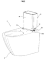
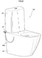
- Fig. 1 is a perspective view showing an entire flush toilet according to a first embodiment of the present invention.
- Fig. 2 is a perspective view showing a flush toilet according to a first embodiment of the present invention with the holding tank cover removed.
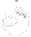
- Fig. 3 is a perspective view showing a flush toilet according to a first embodiment of the present invention with the holding tank removed.
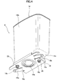
- Fig. 4 is a perspective view of a holding tank according to a first embodiment of the present invention.
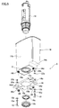
- Fig. 5 is an exploded perspective view of a holding tank according to a first embodiment of the present invention.
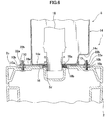
- Fig. 6 is a cross-section showing the attachment of a holding tank to a flush toilet.
- a flush toilet 1 has a flush toilet main body 2 and a holding tank 8 mounted on the flush toilet main body 2 ( Fig. 2 ).
- the holding tank 8 mounted on the flush toilet main body 2 is covered by a holding tank cover 4.
- the flush toilet main body 2 and the holding tank cover 4 are made of a ceramic. Because the inner holding tank 8 is covered by the holding tank cover 4, there is no external exposure of the bolt connecting to the holding tank 8 and the flush toilet main body 2, thereby improving the external appearance of the flush toilet 1. Removal of the holding tank cover 4, as described below, permits the holding tank 8 to be easily attached to and detached from the flush toilet main body 2.
- the flush toilet main body 2 has a bowl portion 2a for receiving waste, and a drain trap pipe 2b extending from the bottom portion of the bowl portion 2a.
- a cleaning switch 6 is provided on the top end surface of the slider , and flush water in the holding tank 8 is spouted into the bowl portion 2a by an operation of this cleaning switch 6, enabling the bowl portion 2a to be cleaned.
- removing the flush toilet 1 holding tank cover 4 exposes the holding tank 8 covered thereby.
- the holding tank 8 is mounted on a tank mounting surface 2c on the flush toilet main body 2.
- the top end surface of the flush toilet main body 2 is formed to be essentially planar, and the tank mounting surface 2c comprises the top end surface rear portion of the flush toilet main body 2. Note that the top end surface of the flush toilet main body 2 and the tank mounting surface 2c do not necessarily have to be coplanar.
- a tank connecting hole 2d for causing flush water to flow into the holding tank 8 is formed on the flush toilet main body 2 tank mounting surface 2c, and two stud bolts 10 as well as three support protuberances 12 for supporting the holding tank 8 are also provided thereon.
- the tank connecting hole 2d is a circular hole provided at approximately the center of the tank mounting surface 2c, and the holding tank 8 is connected to this tank connecting hole 2d.
- Flush water caused to flow from this tank connecting hole 2d into the flush toilet main body 2 is spouted from the rim spout opening (not shown) provided on the upper portion of the bowl portion 2a, and from the jet spout opening (not shown) provided so as to oppose the drain trap pipe 2b, thereby cleaning the bowl portion 2a.
- the stud bolts 10 are arranged in approximately laterally symmetrical positions on both sides of the tank connecting hole 2d, and are attached to the flush toilet main body 2 so as to project vertically upward from the tank mounting surface 2c.
- the support protuberances 12 are formed integrally with the flush toilet main body 2, and project upward from the tank mounting surface 2c. Of the three support protuberances 12, two are disposed in the forward vicinity of the stud bolts 10; the remaining one is formed in the rear vicinity of the tank connecting hole 2d. In the present embodiment, after the ceramic flush toilet main body 2 is formed, each of the support protuberances 12 are ground so that their respective top surfaces are positioned on the same horizontal plane. The holding tank 8 can thus be accurately supported in the horizontal direction, even if there are manufacturing variances in the shape of the flush toilet main body 2 as formed.
- the holding tank 8 has a tank main body 14, an affixing plate 16 serving as the tank affixing portion attached to the bottom portion of the tank main body 14, and a drain valve 18 ( Fig. 5 ) housed inside the tank main body 14.
- the tank main body 14 is a resin receptacle, open at the top end and furnished with a tank bottom surface 14a, a tank side surface 14b extending approximately vertically upward from the tank bottom surface 14a, and a tank shelf portion 14c extending approximately horizontally above the tank bottom surface 14a.
- a tank drain opening 14e for causing flush water to flow out is formed at approximately the center of the tank bottom surface 14a.
- Two plate affixing bolts 14d extending downward from the tank bottom surface 14a are also integrally formed on the tank bottom surface 14a. These two plate affixing bolts 14d are disposed on both sides of the tank drain opening 14e, on an approximately diagonal line on an approximately rectangular surface contacted by the tank main body 14 and the affixing plate 16.
- the affixing plate 16 is an approximately rectangular metal plate, on which are formed two arm portions 16a, which are projecting portions extending from the short sides on both sides; tank affixing holes 16b are respectively provided at the end portions of the arm portions 16a.
- these tank affixing holes 16b are provided in positions respectively corresponding to each of the stud bolts 10.
- the tank affixing holes 16b are disposed on the outside of the region defined by the vertical projection of the closed curve C on the outer perimeter of the tank bottom surface 14a (shown by the thick solid line in Fig. 5 ).
- a flexible portion 16c constituted to be able to easily narrow and elastically deform the width of the arm portions 16a is also disposed at the base portion of each of the arm portions 16a. This enables the arm portions 16a to be easily turned in the vertical direction, and the position of the tank affixing holes 16b to be moved vertically.
- the plate affixing holes 16d are respectively provided at positions corresponding to each of the plate affixing bolts 14d on the affixing plate 16.
- the affixing plate 16 can be affixed to the tank main body 14 by inserting each of the plate affixing bolts 14d respectively into the plate affixing holes 16d and screwing the connecting nuts 20 onto the plate affixing bolts 14d.
- Plate drain hole 16e ( Fig. 5 ) is provided at positions corresponding to the tank drain opening 14e on the affixing plate 16.
- the drain valve 18 is an approximately cylindrical on-off valve housed within the tank main body 14; it is left open for a specified time by an operation of the cleaning switch 6, causing flush water in the tank main body 14 to flow out to the flush toilet main body 2.
- the bottom end portion of the drain valve 18 penetrates the tank main body 14 tank drain opening 14e and the affixing plate 16 plate drain hole 16e, and projects downward from the affixing plate 16.
- a drain valve affixing nut 18a is screwed onto the bottom end portion projecting out from the drain valve 18, and the drain valve 18 is affixed to the tank main body 14. Furthermore, the drain valve 18 bottom end portion is fit into a packing 18b, so that water tightness is secured in conjunction with the flush toilet main body 2.
- stud bolts 10 are caused to project upward from the bottom side of the flush toilet main body 2 tank mounting surface 2c; washers 10a are passed over the stud bolts 10 from the top of the tank mounting surface 2c, and stud bolt affixing nuts 10b are screwed thereon.
- the stud bolts 10 are thus affixed so as to project upward from the tank mounting surface 2c.
- the affixing plate 16 is affixed to the tank bottom surface 14a on the tank main body 14 by connecting nuts 20.
- the drain valve 18 is affixed to the tank main body 14 by the drain valve affixing nut 18a.
- the holding tank 8 assembled in this way is disposed on the flush toilet main body 2 tank mounting surface 2c.
- the holding tank 8 is disposed so that the end portion of the drain valve 18 extending from the bottom of the holding tank 8 is inserted into the tank connecting hole 2d, and the end portion of the two stud bolts 10 extending from the flush toilet main body 2 are respectively inserted into the affixing plate 16 tank affixing holes 16b.
- the packing 18b disposed at the end portion of the drain valve 18 is sandwiched between the tank main body 14 tank bottom surface 14a and the perimeter portion of the tank connecting hole 2d, assuring water tightness between the holding tank 8 and the flush toilet main body 2.
- the holding tank 8 mounted on the tank mounting surface 2c is supported by three support protuberances 12 ( Fig. 3 ) formed on the tank mounting surface 2c.
- the three support protuberances 12 are made coplanar so as to be located on the same horizontal plane, therefore the holding tank 8 supported by each of the support protuberances 12 is accurately oriented on the horizontal.
- washers 22a are disposed on each stud bolt 10 projecting upward from the affixing plate 16 tank affixing holes 16b, and tank affixing nuts 22b are screwed thereon, joining the holding tank 8 to the flush toilet main body 2.
- the stud bolts 10 and the tank affixing nuts 22b thus comprise an affixing means.
- the tank main body is joined to the flush toilet main body by tightening tank affixing nuts from the outside of the flush toilet main body and the tank main body, therefore the holding tank can be joined to the flush toilet main body with good workability.
- the tank main body and the affixing plate are formed as separate units, therefore they can be formed of differing materials, and appropriate materials can be respectively selected for the tank main body and the tank affixing portion.
- the use of resin to form the flush water-contacting tank main body prevents degradation of the tank main body by rust and the like, and the use of metal to form the tank affixing portion, on which a large force acts when affixing the holding tank, prevents breakage of the affixing plate when affixing the holding tank.
- the tank main body and the affixing plate are affixed by plate affixing bolts integrally formed in the tank main body, therefore the tank main body and the affixing plate can be bolted together without forming a hole in the tank main body, and leakage of water from the tank main body can be securely prevented.
- each plate affixing bolt is disposed on approximately diagonal lines on an essentially rectangular plane contacted by the tank main body and the affixing plate, therefore the tank main body side surface can effectively resist an external force pressing in the direction of the short sides of said rectangle, and the tank main body can be strongly affixed to the affixing plate.
- the affixing plate is furnished with a flexible portion, therefore even when an excessive force operates on the arm portion due to the tank affixing nuts, elastic deformation of the flexible portion allows movement of the arm portion, thereby avoiding deformation of the entire affixing plate.
- This allows the prevention of problems such as plate affixing bolt damage caused by deformation of the entire affixing plate.
- the affixing plate is mounted on the tank mounting surface on the flush toilet main body or on the support protuberances, deformation of the entire affixing plate can be avoided by the elastic deformation of the flexible portion, even if there is dimensional variability in the vertical direction due to manufacturing variances or the like.
- a tank shelf portion is provided on the tank main body so as to protrude above the tank affixing nut, therefore the tank main body internal volume can be enlarged while enabling the tank affixing nut to be tightened from outside the tank main body.
- the holding tank is mounted on three support protuberances, therefore the holding tank can be securely supported without any looseness even when there are manufacturing variances in the shape of the flush toilet main body.
- the holding tank can be accurately horizontally supported.
- the affixing means for joining the affixing plate and the flush toilet main body comprised stud bolts and tank affixing nuts, but other means may also be used to effect this joining.
- the tank main body and the plate affixing bolts were comprised as a single integral unit, but the tank main body and the plate affixing bolts can also be separately comprised such that the plate affixing bolts can also be attached and removed on the outside of the bottom surface of the tank main body.
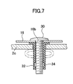
- Fig. 7 is a cross-section showing a variation of the affixing means.
- the affixing means comprises tank affixing bolt 30, a cylindrical elastically deforming member 32 through which the tank affixing bolt 30 passes, and an elastic deformation nut 34.
- the tank affixing bolts 30 are inserted from the top side of the affixing plate 16 tank affixing holes 16b.
- the outside perimeter of the elastic deformation nuts 34 are affixed to the inside wall surface at the lower portion of the cylindrical elastically deforming members 32.
- the elastically deforming members 32 are placed on top of the tank affixing bolts 30 projecting from the bottom side of the affixing plate 16, and the elastic deformation nuts 34 are screwed onto the tank affixing bolts 30.
- the elastically deforming members 32 are thus attached to the affixing plate 16.
- the elastically deforming members 32 attached to the affixing plate 16 are inserted into holes formed in the flush toilet main body 2 tank mounting surface 2c.
- the elastic deformation nuts 34 are pulled up by screw action.
- the elastically deforming member 32 deform as shown by the imaginary lines in Fig. 7 , and the tank affixing bolts 30 can no longer be pulled out from the flush toilet main body 2.
- the affixing plate 16 is thus affixed to the flush toilet main body 2.
- the elastically deforming members 32 were expanded on the back side of the tank mounting surface 2c to affix the tank affixing bolts 30, but when the tank mounting surface 2c is thick, the elastically deforming members 32 can also be caused to expand inside the holes in the tank mounting surface 2c. In that case, the tank affixing bolts 30 are affixed by friction between the expanded elastically deforming members 32 and the inner wall surface of the holes.
- the snap fasteners, split pins, or the like may be used as affixing means.
- a flush toilet according to second embodiment of the present invention.
- the attachment of a stop cock for stopping the supply of water to a bidet such as washlet® differs from the above-described first embodiment. Therefore we will here discuss only points of difference with the first embodiment.
- Fig. 8 is a perspective view showing an entire flush toilet according to a second embodiment of the present invention.
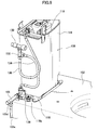
- Fig. 9 is a perspective view showing an expanded view of the holding tank with the holding tank cover removed in a flush toilet according to the present embodiment.
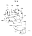
- Fig. 10 is a perspective view showing a water supply means affixing plate for attaching the stop cock to the affixing plate.
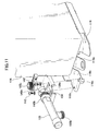
- Fig. 11 is a partial perspective view showing the attachment of the stop cock to the affixing plate.
- the flush toilet 100 comprises a flush toilet main body 102 and a holding tank 108 ( Fig. 9 ).
- the holding tank 108 is covered by a holding tank cover 104.
- a stop cock 105 serving as a water supply means is also attached so as to project out from the lower portion of the holding tank cover 104 side surface.
- the holding tank 108 has a tank main body 114, an affixing plate 116 serving as a tank affixing portion attached at the lower portion of the tank main body 114, and a drain valve 118 housed inside the tank main body 114.
- a water supply means affixing plate 138 for attaching the stop cock 105 is also attached to the affixing plate 116.
- the affixing plate 116 is essentially a rectangular metal plate, on which are formed two projecting portion or arm portions 116a (only one of which is shown in Fig. 9 ) extending from the short ends on both sides of the rectangle. These arm portions 116a are affixed to the flush toilet main body 102 by each of the stud bolts and nuts.
- a water supply means affixing portion 116b serving as a second projecting portion is formed on the affixing plate 116.
- the water supply means affixing portion 116b is formed to project as a single piece with the affixing plate 116 into the same plane as the arm portions 116a, behind one of the arm portions 116a.
- the water supply means affixing plate 138 is a metal plate bent into an approximately L shape; the long side of the L shape is screw-fastened to the water supply means affixing portion 116b to overlap the affixing plate 116.
- two long holes 138a serving as affixing position adjustment means are formed on the water supply means affixing plate 138 in order to attach the water supply means affixing plate 138 to the water supply means affixing portion 116b in a position-adjustable manner. These long holes 138a allow for adjustment of the position at which the water supply means affixing plate 138 is screw-fastened to the water supply means affixing portion 116b, in the horizontal direction of the flush toilet.
- the stop cock 105 is affixed at its base end to the short side of L-shaped water supply means affixing plate 138 by the affixing band 140a; the end portion thereof is affixed to the long side of the water supply means affixing plate 138 by the affixing band 140.
- These affixing bands 140a and 140b comprise a thin metal plate having a specified width, bent into an approximately U shape; tightening around the stop cock 105 affixes the stop cock 105 to the water supply means affixing plate 138.
- a general purpose product suited to the type of the stop cock 105 may be used for these affixing bands.
- mains water guided from a flush water guide portion 130 is branched by a T pipe 132; one of those branches is sent to the stop cock 105 via a water supply pipe 134; the other is guided into the tank main body 114 via a water supply pipe 136.
- Flush water sent to the stop cock 105 is supplied to a local flush device (not shown) via a flexible hose (105) connected to the stop cock 105.
- the stop cock 105 is left open during normal use, and is closed during maintenance of the local flush device or the like.
- the stop cock 105 is affixed to the water supply means affixing plate 138 by affixing bands 140a and 140b.
- two screws 142 are passed through each of the long holes 138a in the water supply means affixing plate 138 and screwed into each of the female screw holes 116c provided in the water supply means affixing portion 116b.
- the water supply means affixing plate 138 is thus temporarily affixed to the water supply means affixing portion 116b.
- each of the screws 142 is lightly tightened, and the water supply means affixing plate 138 is allowed to slide along the long holes 138a.
- a flexible hose 105a is connected to a flexible hose attaching portion 105b on the stop cock 105, and the water supply pipe 134 is connected to a water supply pipe attachment portion 105c thereon. Furthermore, the water supply means affixing plate 138 is slid along the long holes 138a to position the stop cock 105 at a specified position. Finally, each of the screws 142 is tightened, and the water supply means affixing plate 138 is affixed to the water supply means affixing portion 116b. Note that the process by which the flexible hose 105a is connected to the stop cock 105 may also be implemented after positioning the stop cock 105 at a specified position and fully tightening each of the screws 142.
- any dimensional manufacturing variances in the flush toilet main body 102 or the like can be absorbed, and the stop cock 105 can be positioned at the correct position. Also, the position of the stop cock 105 is adjusted after the flexible hose 105a has been connected to the stop cock 105, therefore the stop cock 105 can be positioned even in a location where the cap nut 105d ( Fig. 9 ) for affixing the flexible hose 105a to the stop cock 105 is extremely close to the side surface of the flush toilet main body 102, such that tightening the cap nut 105d is difficult.
- a stop cock is attached to an affixing plate, therefore the stop cock can be affixed without providing through holes or the like in the tank main body for attaching the stop cock, and the risk of leakage or the like associated with attaching the stop cock can be avoided.
- the stop cock is attached to an affixing plate, therefore the stop cock can be removed together with the tank main body, thus avoiding interference by the stop cock and the tank main body when attaching or removing same.
- the stop cock in the flush toilet of the present embodiment is affixed to a water supply means affixing portion via a water supply means affixing plate, therefore the stop cock can be easily affixed.
- stop cock and the like can be attached to the same water supply means affixing portion by changing the water supply means affixing plate.
- the stop cock is affixed by an affixing band, therefore a general purpose product can be used for this purpose.
- affixing using an affixing band can improve ease of installation compared to using a water supply means affixing means which covers and hides the water supply means from above.
- the position at which the water supply means plate is affixed is adjusted using long holes, therefore shape variances in the flush toilet main body and the like can be absorbed, and the stop cock can be affixed at the correct position.
- a stop cock was attached as a water supply means to the holding tank, but a valve unit such as a constant flow valve, water supply piping, or various water supply means can also be attached to the holding tank in lieu of a stop cock.
- the water supply means affixing plate was positionally adjustable on the side of the flush toilet, but it may also be constituted as a position adjustment means able to slide or rotate in any desired direction.
- a flush toilet holding tank (8) mounted on a flush toilet main body (2) and used by joining to the flush toilet main body, comprising: a tank bottom surface (14a) on which a tank drain opening is provided for causing flush water to flow to the flush toilet main body; a tank main body (14) furnished with a tank side surface (14b) extending upward from the tank bottom surface; a tank affixing portion (16) furnished with an projecting portion (16a) protruding outside of an area [defined by] vertically projecting a closed curve (C) at the outside perimeter of the tank bottom surface; and an affixing means (10, 22b) for joining the tank main body to the flush toilet main body via a tank affixing portion by affixing the projecting portion to the flush toilet main body by an operation
- the embodiments described above comprise a separate tank main body and affixing plate serving as a tank affixing portion, but these may also be constituted as a single piece.
Landscapes
- Health & Medical Sciences (AREA)
- Life Sciences & Earth Sciences (AREA)
- Engineering & Computer Science (AREA)
- Hydrology & Water Resources (AREA)
- Public Health (AREA)
- Water Supply & Treatment (AREA)
- Sanitary Device For Flush Toilet (AREA)
Applications Claiming Priority (2)
| Application Number | Priority Date | Filing Date | Title |
|---|---|---|---|
| JP2008142989 | 2008-05-30 | ||
| JP2009006782A JP5648267B2 (ja) | 2008-05-30 | 2009-01-15 | 貯水タンク及びそれを備えた水洗大便器 |
Publications (3)
| Publication Number | Publication Date |
|---|---|
| EP2128351A2 true EP2128351A2 (de) | 2009-12-02 |
| EP2128351A3 EP2128351A3 (de) | 2012-10-17 |
| EP2128351B1 EP2128351B1 (de) | 2013-11-06 |
Family
ID=41055564
Family Applications (1)
| Application Number | Title | Priority Date | Filing Date |
|---|---|---|---|
| EP20090161578 Not-in-force EP2128351B1 (de) | 2008-05-30 | 2009-05-29 | Haltetank und Spültoilette damit |
Country Status (3)
| Country | Link |
|---|---|
| EP (1) | EP2128351B1 (de) |
| JP (1) | JP5648267B2 (de) |
| CN (1) | CN101591931B (de) |
Cited By (7)
| Publication number | Priority date | Publication date | Assignee | Title |
|---|---|---|---|---|
| EP2868820A1 (de) * | 2013-10-31 | 2015-05-06 | Villeroy & Boch AG | Spülkastenanordnung |
| WO2016105292A3 (en) * | 2014-12-26 | 2016-07-28 | ECZACIBAŞI YAPI GEREÇLERi SANAYl VE TİCARET ANONİM SİRKETİ | Reservoir mounting kit and the mounting method thereof |
| EP3124710A1 (de) * | 2015-07-28 | 2017-02-01 | Oliveira & Irmao S.A. | Montagesystem für einen spültank, insbesondere für einen spültank aus keramik. |
| US20170037609A1 (en) * | 2012-05-23 | 2017-02-09 | Kohler Co. | Toilet coupling |
| US10214890B2 (en) | 2012-05-23 | 2019-02-26 | Kohler Co. | Toilet coupling |
| US10738448B2 (en) | 2017-12-04 | 2020-08-11 | Kohler Co. | Toilet coupling |
| US12497769B2 (en) | 2023-07-31 | 2025-12-16 | Toto Ltd. | Flush toilet apparatus |
Families Citing this family (6)
| Publication number | Priority date | Publication date | Assignee | Title |
|---|---|---|---|---|
| CN103201436A (zh) * | 2010-09-03 | 2013-07-10 | 埃克扎西巴西建筑材料工业有限公司 | 水箱安装系统 |
| CN107190825A (zh) * | 2017-07-12 | 2017-09-22 | 陈玩丽 | 一种分体式陶瓷马桶 |
| JP7255406B2 (ja) * | 2019-07-25 | 2023-04-11 | Toto株式会社 | 排水弁装置、洗浄水タンク装置および水洗大便器 |
| JP6993620B2 (ja) * | 2019-09-27 | 2022-01-13 | Toto株式会社 | 水洗大便器 |
| JP2023034308A (ja) * | 2021-08-30 | 2023-03-13 | Toto株式会社 | 水洗大便器 |
| IT202300014916A1 (it) * | 2023-07-17 | 2025-01-17 | Oli Sist Sanitarios S A | Dispositivo di fissaggio per fissare una cassetta di risciacquo su un vaso sanitario |
Citations (5)
| Publication number | Priority date | Publication date | Assignee | Title |
|---|---|---|---|---|
| US2108625A (en) | 1936-12-31 | 1938-02-15 | Bert O Tilden | Water closet combination |
| DE2724413A1 (de) | 1977-05-28 | 1978-12-07 | Abu Plast Kunststoff | Spuelkastenpodest |
| EP0187657A2 (de) | 1985-01-08 | 1986-07-16 | Kohler Co. | Dichtung an einem Toilettenspülkasten |
| US4924533A (en) | 1988-11-14 | 1990-05-15 | American Standard Inc. | Coupling means for toilet tank and bowl assembly |
| US6728976B1 (en) | 2003-01-20 | 2004-05-04 | Kohler Co. | Toilet tank attachment bracket with unitary spring arm |
Family Cites Families (9)
| Publication number | Priority date | Publication date | Assignee | Title |
|---|---|---|---|---|
| JPS57119861U (de) * | 1981-01-14 | 1982-07-26 | ||
| JPS60109435A (ja) * | 1983-11-18 | 1985-06-14 | 株式会社イナックス | ロ−タンク密結式便器 |
| JPS6216172U (de) * | 1985-07-12 | 1987-01-30 | ||
| JPH0995990A (ja) * | 1995-09-29 | 1997-04-08 | Toto Ltd | 便器装置 |
| CN2272462Y (zh) * | 1996-04-08 | 1998-01-14 | 梁国新 | 无污染气压式坐厕冲洗水箱 |
| JPH1161935A (ja) | 1997-08-25 | 1999-03-05 | Inax Corp | カバーボックスの設置構造 |
| JP3503532B2 (ja) * | 1999-06-23 | 2004-03-08 | 松下電工株式会社 | 便器用手摺りの取付構造 |
| JP2004285670A (ja) * | 2003-03-20 | 2004-10-14 | Toto Ltd | 水洗便器 |
| CN2769386Y (zh) * | 2005-01-31 | 2006-04-05 | 陶精(福建)实业有限公司 | 抽水马桶 |
-
2009
- 2009-01-15 JP JP2009006782A patent/JP5648267B2/ja not_active Expired - Fee Related
- 2009-05-25 CN CN2009102032415A patent/CN101591931B/zh active Active
- 2009-05-29 EP EP20090161578 patent/EP2128351B1/de not_active Not-in-force
Patent Citations (5)
| Publication number | Priority date | Publication date | Assignee | Title |
|---|---|---|---|---|
| US2108625A (en) | 1936-12-31 | 1938-02-15 | Bert O Tilden | Water closet combination |
| DE2724413A1 (de) | 1977-05-28 | 1978-12-07 | Abu Plast Kunststoff | Spuelkastenpodest |
| EP0187657A2 (de) | 1985-01-08 | 1986-07-16 | Kohler Co. | Dichtung an einem Toilettenspülkasten |
| US4924533A (en) | 1988-11-14 | 1990-05-15 | American Standard Inc. | Coupling means for toilet tank and bowl assembly |
| US6728976B1 (en) | 2003-01-20 | 2004-05-04 | Kohler Co. | Toilet tank attachment bracket with unitary spring arm |
Cited By (10)
| Publication number | Priority date | Publication date | Assignee | Title |
|---|---|---|---|---|
| US20170037609A1 (en) * | 2012-05-23 | 2017-02-09 | Kohler Co. | Toilet coupling |
| US10208471B2 (en) | 2012-05-23 | 2019-02-19 | Kohler Co. | Toilet coupling |
| US10214890B2 (en) | 2012-05-23 | 2019-02-26 | Kohler Co. | Toilet coupling |
| US10260221B2 (en) * | 2012-05-23 | 2019-04-16 | Kohler Co. | Toilet coupling |
| US10995482B2 (en) | 2012-05-23 | 2021-05-04 | Kohler Co. | Toilet coupling |
| EP2868820A1 (de) * | 2013-10-31 | 2015-05-06 | Villeroy & Boch AG | Spülkastenanordnung |
| WO2016105292A3 (en) * | 2014-12-26 | 2016-07-28 | ECZACIBAŞI YAPI GEREÇLERi SANAYl VE TİCARET ANONİM SİRKETİ | Reservoir mounting kit and the mounting method thereof |
| EP3124710A1 (de) * | 2015-07-28 | 2017-02-01 | Oliveira & Irmao S.A. | Montagesystem für einen spültank, insbesondere für einen spültank aus keramik. |
| US10738448B2 (en) | 2017-12-04 | 2020-08-11 | Kohler Co. | Toilet coupling |
| US12497769B2 (en) | 2023-07-31 | 2025-12-16 | Toto Ltd. | Flush toilet apparatus |
Also Published As
| Publication number | Publication date |
|---|---|
| CN101591931B (zh) | 2011-06-01 |
| JP5648267B2 (ja) | 2015-01-07 |
| CN101591931A (zh) | 2009-12-02 |
| EP2128351B1 (de) | 2013-11-06 |
| EP2128351A3 (de) | 2012-10-17 |
| JP2010007451A (ja) | 2010-01-14 |
Similar Documents
| Publication | Publication Date | Title |
|---|---|---|
| EP2128351B1 (de) | Haltetank und Spültoilette damit | |
| US11759011B2 (en) | Mounting system for sink | |
| US6073278A (en) | Snap on fluid overflow plate for bathtubs | |
| US8769736B2 (en) | Device for concealing a plate associated with overflow plumbing | |
| US7210493B1 (en) | Faucet assembly mounting apparatus | |
| CA2419891A1 (en) | Flush valve mounting assembly | |
| US9556600B2 (en) | Offsetting dual flush adapter | |
| US20100017957A1 (en) | Gasket for installing a sink in a counter and methods of using same | |
| JP2002000479A (ja) | 流し鉢の設置構造 | |
| JP2961502B2 (ja) | 点検口の蓋の取付方法とその方法に使用される取付具 | |
| US4459736A (en) | Shim for electrical receptacle or switch | |
| JP5228351B2 (ja) | 手洗装置 | |
| JP6785400B2 (ja) | 排水器の取付構造 | |
| US1922647A (en) | Plumbing device | |
| JPH0255570B2 (de) | ||
| JP4600274B2 (ja) | 浴室カウンタの構造 | |
| JPS6013915Y2 (ja) | 水槽装着装置 | |
| JPH0433033Y2 (de) | ||
| JPH069086Y2 (ja) | 浴室用給水栓取付装置 | |
| JPH09144083A (ja) | 水栓の取付構造 | |
| JPH0643264Y2 (ja) | 洗面器用ブラケット | |
| JP2002275965A (ja) | 湯水混合水栓用棚 | |
| JPH04107688U (ja) | バスエプロンの取付装置 | |
| JP2001070190A (ja) | カウンター取付部の構造 | |
| JPH11217857A (ja) | 配管ユニット |
Legal Events
| Date | Code | Title | Description |
|---|---|---|---|
| PUAI | Public reference made under article 153(3) epc to a published international application that has entered the european phase |
Free format text: ORIGINAL CODE: 0009012 |
|
| AK | Designated contracting states |
Kind code of ref document: A2 Designated state(s): AT BE BG CH CY CZ DE DK EE ES FI FR GB GR HR HU IE IS IT LI LT LU LV MC MK MT NL NO PL PT RO SE SI SK TR |
|
| PUAL | Search report despatched |
Free format text: ORIGINAL CODE: 0009013 |
|
| AK | Designated contracting states |
Kind code of ref document: A3 Designated state(s): AT BE BG CH CY CZ DE DK EE ES FI FR GB GR HR HU IE IS IT LI LT LU LV MC MK MT NL NO PL PT RO SE SI SK TR |
|
| AX | Request for extension of the european patent |
Extension state: AL BA RS |
|
| RIC1 | Information provided on ipc code assigned before grant |
Ipc: E03D 1/01 20060101ALI20120910BHEP Ipc: E03D 1/26 20060101AFI20120910BHEP |
|
| RAP1 | Party data changed (applicant data changed or rights of an application transferred) |
Owner name: TOTO LTD. |
|
| 17P | Request for examination filed |
Effective date: 20130411 |
|
| GRAP | Despatch of communication of intention to grant a patent |
Free format text: ORIGINAL CODE: EPIDOSNIGR1 |
|
| INTG | Intention to grant announced |
Effective date: 20130531 |
|
| RIN1 | Information on inventor provided before grant (corrected) |
Inventor name: MATSUDA, HARUKI Inventor name: SUEMATSU, MASAMICHI Inventor name: KIDO, TSUTOMU Inventor name: AGARIE, SHINJI |
|
| GRAS | Grant fee paid |
Free format text: ORIGINAL CODE: EPIDOSNIGR3 |
|
| GRAA | (expected) grant |
Free format text: ORIGINAL CODE: 0009210 |
|
| AK | Designated contracting states |
Kind code of ref document: B1 Designated state(s): AT BE BG CH CY CZ DE DK EE ES FI FR GB GR HR HU IE IS IT LI LT LU LV MC MK MT NL NO PL PT RO SE SI SK TR |
|
| REG | Reference to a national code |
Ref country code: GB Ref legal event code: FG4D |
|
| REG | Reference to a national code |
Ref country code: CH Ref legal event code: EP |
|
| REG | Reference to a national code |
Ref country code: AT Ref legal event code: REF Ref document number: 639608 Country of ref document: AT Kind code of ref document: T Effective date: 20131215 |
|
| REG | Reference to a national code |
Ref country code: IE Ref legal event code: FG4D |
|
| REG | Reference to a national code |
Ref country code: DE Ref legal event code: R096 Ref document number: 602009019841 Country of ref document: DE Effective date: 20140109 |
|
| REG | Reference to a national code |
Ref country code: NL Ref legal event code: VDEP Effective date: 20131106 |
|
| REG | Reference to a national code |
Ref country code: AT Ref legal event code: MK05 Ref document number: 639608 Country of ref document: AT Kind code of ref document: T Effective date: 20131106 |
|
| REG | Reference to a national code |
Ref country code: LT Ref legal event code: MG4D |
|
| PG25 | Lapsed in a contracting state [announced via postgrant information from national office to epo] |
Ref country code: LT Free format text: LAPSE BECAUSE OF FAILURE TO SUBMIT A TRANSLATION OF THE DESCRIPTION OR TO PAY THE FEE WITHIN THE PRESCRIBED TIME-LIMIT Effective date: 20131106 Ref country code: SE Free format text: LAPSE BECAUSE OF FAILURE TO SUBMIT A TRANSLATION OF THE DESCRIPTION OR TO PAY THE FEE WITHIN THE PRESCRIBED TIME-LIMIT Effective date: 20131106 Ref country code: HR Free format text: LAPSE BECAUSE OF FAILURE TO SUBMIT A TRANSLATION OF THE DESCRIPTION OR TO PAY THE FEE WITHIN THE PRESCRIBED TIME-LIMIT Effective date: 20131106 Ref country code: NL Free format text: LAPSE BECAUSE OF FAILURE TO SUBMIT A TRANSLATION OF THE DESCRIPTION OR TO PAY THE FEE WITHIN THE PRESCRIBED TIME-LIMIT Effective date: 20131106 Ref country code: FI Free format text: LAPSE BECAUSE OF FAILURE TO SUBMIT A TRANSLATION OF THE DESCRIPTION OR TO PAY THE FEE WITHIN THE PRESCRIBED TIME-LIMIT Effective date: 20131106 Ref country code: IS Free format text: LAPSE BECAUSE OF FAILURE TO SUBMIT A TRANSLATION OF THE DESCRIPTION OR TO PAY THE FEE WITHIN THE PRESCRIBED TIME-LIMIT Effective date: 20140306 Ref country code: NO Free format text: LAPSE BECAUSE OF FAILURE TO SUBMIT A TRANSLATION OF THE DESCRIPTION OR TO PAY THE FEE WITHIN THE PRESCRIBED TIME-LIMIT Effective date: 20140206 |
|
| PG25 | Lapsed in a contracting state [announced via postgrant information from national office to epo] |
Ref country code: ES Free format text: LAPSE BECAUSE OF FAILURE TO SUBMIT A TRANSLATION OF THE DESCRIPTION OR TO PAY THE FEE WITHIN THE PRESCRIBED TIME-LIMIT Effective date: 20131106 Ref country code: BE Free format text: LAPSE BECAUSE OF FAILURE TO SUBMIT A TRANSLATION OF THE DESCRIPTION OR TO PAY THE FEE WITHIN THE PRESCRIBED TIME-LIMIT Effective date: 20131106 Ref country code: AT Free format text: LAPSE BECAUSE OF FAILURE TO SUBMIT A TRANSLATION OF THE DESCRIPTION OR TO PAY THE FEE WITHIN THE PRESCRIBED TIME-LIMIT Effective date: 20131106 Ref country code: LV Free format text: LAPSE BECAUSE OF FAILURE TO SUBMIT A TRANSLATION OF THE DESCRIPTION OR TO PAY THE FEE WITHIN THE PRESCRIBED TIME-LIMIT Effective date: 20131106 |
|
| PG25 | Lapsed in a contracting state [announced via postgrant information from national office to epo] |
Ref country code: PT Free format text: LAPSE BECAUSE OF FAILURE TO SUBMIT A TRANSLATION OF THE DESCRIPTION OR TO PAY THE FEE WITHIN THE PRESCRIBED TIME-LIMIT Effective date: 20140306 |
|
| PG25 | Lapsed in a contracting state [announced via postgrant information from national office to epo] |
Ref country code: EE Free format text: LAPSE BECAUSE OF FAILURE TO SUBMIT A TRANSLATION OF THE DESCRIPTION OR TO PAY THE FEE WITHIN THE PRESCRIBED TIME-LIMIT Effective date: 20131106 |
|
| REG | Reference to a national code |
Ref country code: DE Ref legal event code: R097 Ref document number: 602009019841 Country of ref document: DE |
|
| PG25 | Lapsed in a contracting state [announced via postgrant information from national office to epo] |
Ref country code: SK Free format text: LAPSE BECAUSE OF FAILURE TO SUBMIT A TRANSLATION OF THE DESCRIPTION OR TO PAY THE FEE WITHIN THE PRESCRIBED TIME-LIMIT Effective date: 20131106 Ref country code: CZ Free format text: LAPSE BECAUSE OF FAILURE TO SUBMIT A TRANSLATION OF THE DESCRIPTION OR TO PAY THE FEE WITHIN THE PRESCRIBED TIME-LIMIT Effective date: 20131106 Ref country code: RO Free format text: LAPSE BECAUSE OF FAILURE TO SUBMIT A TRANSLATION OF THE DESCRIPTION OR TO PAY THE FEE WITHIN THE PRESCRIBED TIME-LIMIT Effective date: 20131106 Ref country code: PL Free format text: LAPSE BECAUSE OF FAILURE TO SUBMIT A TRANSLATION OF THE DESCRIPTION OR TO PAY THE FEE WITHIN THE PRESCRIBED TIME-LIMIT Effective date: 20131106 Ref country code: IT Free format text: LAPSE BECAUSE OF FAILURE TO SUBMIT A TRANSLATION OF THE DESCRIPTION OR TO PAY THE FEE WITHIN THE PRESCRIBED TIME-LIMIT Effective date: 20131106 |
|
| PLBE | No opposition filed within time limit |
Free format text: ORIGINAL CODE: 0009261 |
|
| STAA | Information on the status of an ep patent application or granted ep patent |
Free format text: STATUS: NO OPPOSITION FILED WITHIN TIME LIMIT |
|
| PG25 | Lapsed in a contracting state [announced via postgrant information from national office to epo] |
Ref country code: DK Free format text: LAPSE BECAUSE OF FAILURE TO SUBMIT A TRANSLATION OF THE DESCRIPTION OR TO PAY THE FEE WITHIN THE PRESCRIBED TIME-LIMIT Effective date: 20131106 |
|
| 26N | No opposition filed |
Effective date: 20140807 |
|
| REG | Reference to a national code |
Ref country code: DE Ref legal event code: R097 Ref document number: 602009019841 Country of ref document: DE Effective date: 20140807 |
|
| PG25 | Lapsed in a contracting state [announced via postgrant information from national office to epo] |
Ref country code: LU Free format text: LAPSE BECAUSE OF FAILURE TO SUBMIT A TRANSLATION OF THE DESCRIPTION OR TO PAY THE FEE WITHIN THE PRESCRIBED TIME-LIMIT Effective date: 20140529 |
|
| REG | Reference to a national code |
Ref country code: CH Ref legal event code: PL |
|
| GBPC | Gb: european patent ceased through non-payment of renewal fee |
Effective date: 20140529 |
|
| PG25 | Lapsed in a contracting state [announced via postgrant information from national office to epo] |
Ref country code: MC Free format text: LAPSE BECAUSE OF FAILURE TO SUBMIT A TRANSLATION OF THE DESCRIPTION OR TO PAY THE FEE WITHIN THE PRESCRIBED TIME-LIMIT Effective date: 20131106 Ref country code: LI Free format text: LAPSE BECAUSE OF NON-PAYMENT OF DUE FEES Effective date: 20140531 Ref country code: CH Free format text: LAPSE BECAUSE OF NON-PAYMENT OF DUE FEES Effective date: 20140531 |
|
| REG | Reference to a national code |
Ref country code: IE Ref legal event code: MM4A |
|
| PG25 | Lapsed in a contracting state [announced via postgrant information from national office to epo] |
Ref country code: SI Free format text: LAPSE BECAUSE OF FAILURE TO SUBMIT A TRANSLATION OF THE DESCRIPTION OR TO PAY THE FEE WITHIN THE PRESCRIBED TIME-LIMIT Effective date: 20131106 |
|
| REG | Reference to a national code |
Ref country code: FR Ref legal event code: ST Effective date: 20150130 |
|
| PG25 | Lapsed in a contracting state [announced via postgrant information from national office to epo] |
Ref country code: IE Free format text: LAPSE BECAUSE OF NON-PAYMENT OF DUE FEES Effective date: 20140529 |
|
| PG25 | Lapsed in a contracting state [announced via postgrant information from national office to epo] |
Ref country code: FR Free format text: LAPSE BECAUSE OF NON-PAYMENT OF DUE FEES Effective date: 20140602 Ref country code: GB Free format text: LAPSE BECAUSE OF NON-PAYMENT OF DUE FEES Effective date: 20140529 |
|
| PG25 | Lapsed in a contracting state [announced via postgrant information from national office to epo] |
Ref country code: MT Free format text: LAPSE BECAUSE OF FAILURE TO SUBMIT A TRANSLATION OF THE DESCRIPTION OR TO PAY THE FEE WITHIN THE PRESCRIBED TIME-LIMIT Effective date: 20131106 |
|
| PG25 | Lapsed in a contracting state [announced via postgrant information from national office to epo] |
Ref country code: BG Free format text: LAPSE BECAUSE OF FAILURE TO SUBMIT A TRANSLATION OF THE DESCRIPTION OR TO PAY THE FEE WITHIN THE PRESCRIBED TIME-LIMIT Effective date: 20131106 Ref country code: GR Free format text: LAPSE BECAUSE OF FAILURE TO SUBMIT A TRANSLATION OF THE DESCRIPTION OR TO PAY THE FEE WITHIN THE PRESCRIBED TIME-LIMIT Effective date: 20140207 Ref country code: CY Free format text: LAPSE BECAUSE OF FAILURE TO SUBMIT A TRANSLATION OF THE DESCRIPTION OR TO PAY THE FEE WITHIN THE PRESCRIBED TIME-LIMIT Effective date: 20131106 |
|
| PG25 | Lapsed in a contracting state [announced via postgrant information from national office to epo] |
Ref country code: HU Free format text: LAPSE BECAUSE OF FAILURE TO SUBMIT A TRANSLATION OF THE DESCRIPTION OR TO PAY THE FEE WITHIN THE PRESCRIBED TIME-LIMIT; INVALID AB INITIO Effective date: 20090529 Ref country code: TR Free format text: LAPSE BECAUSE OF FAILURE TO SUBMIT A TRANSLATION OF THE DESCRIPTION OR TO PAY THE FEE WITHIN THE PRESCRIBED TIME-LIMIT Effective date: 20131106 |
|
| PG25 | Lapsed in a contracting state [announced via postgrant information from national office to epo] |
Ref country code: MK Free format text: LAPSE BECAUSE OF FAILURE TO SUBMIT A TRANSLATION OF THE DESCRIPTION OR TO PAY THE FEE WITHIN THE PRESCRIBED TIME-LIMIT Effective date: 20131106 |
|
| PGFP | Annual fee paid to national office [announced via postgrant information from national office to epo] |
Ref country code: DE Payment date: 20240517 Year of fee payment: 16 |
|
| REG | Reference to a national code |
Ref country code: DE Ref legal event code: R119 Ref document number: 602009019841 Country of ref document: DE |