EP2127883A1 - Printer, ink circulation method and initial ink installation method - Google Patents
Printer, ink circulation method and initial ink installation method Download PDFInfo
- Publication number
- EP2127883A1 EP2127883A1 EP09006830A EP09006830A EP2127883A1 EP 2127883 A1 EP2127883 A1 EP 2127883A1 EP 09006830 A EP09006830 A EP 09006830A EP 09006830 A EP09006830 A EP 09006830A EP 2127883 A1 EP2127883 A1 EP 2127883A1
- Authority
- EP
- European Patent Office
- Prior art keywords
- ink
- ink tank
- head
- tank
- passage
- Prior art date
- Legal status (The legal status is an assumption and is not a legal conclusion. Google has not performed a legal analysis and makes no representation as to the accuracy of the status listed.)
- Withdrawn
Links
- 238000009434 installation Methods 0.000 title claims description 20
- 238000000034 method Methods 0.000 title claims description 18
- 238000007872 degassing Methods 0.000 claims abstract description 31
- 239000007788 liquid Substances 0.000 claims description 62
- 238000007639 printing Methods 0.000 claims description 26
- 238000007789 sealing Methods 0.000 claims description 6
- 230000007246 mechanism Effects 0.000 description 35
- 239000000463 material Substances 0.000 description 27
- 230000001105 regulatory effect Effects 0.000 description 20
- 238000010276 construction Methods 0.000 description 11
- 230000006837 decompression Effects 0.000 description 7
- 239000003086 colorant Substances 0.000 description 4
- 238000013461 design Methods 0.000 description 4
- 238000004519 manufacturing process Methods 0.000 description 4
- 238000005259 measurement Methods 0.000 description 4
- 238000013019 agitation Methods 0.000 description 3
- 230000000052 comparative effect Effects 0.000 description 3
- 230000007423 decrease Effects 0.000 description 3
- 238000004090 dissolution Methods 0.000 description 3
- 230000000694 effects Effects 0.000 description 3
- 230000005484 gravity Effects 0.000 description 3
- 230000005499 meniscus Effects 0.000 description 3
- 239000013307 optical fiber Substances 0.000 description 3
- 230000002159 abnormal effect Effects 0.000 description 2
- 238000001816 cooling Methods 0.000 description 2
- 238000012423 maintenance Methods 0.000 description 2
- 239000000126 substance Substances 0.000 description 2
- XLYOFNOQVPJJNP-UHFFFAOYSA-N water Substances O XLYOFNOQVPJJNP-UHFFFAOYSA-N 0.000 description 2
- 238000004804 winding Methods 0.000 description 2
- 230000015572 biosynthetic process Effects 0.000 description 1
- 239000003795 chemical substances by application Substances 0.000 description 1
- 239000000470 constituent Substances 0.000 description 1
- 230000003203 everyday effect Effects 0.000 description 1
- 238000010438 heat treatment Methods 0.000 description 1
- 238000012986 modification Methods 0.000 description 1
- 230000004048 modification Effects 0.000 description 1
- 230000010355 oscillation Effects 0.000 description 1
- 239000002245 particle Substances 0.000 description 1
- 239000000049 pigment Substances 0.000 description 1
- 238000001556 precipitation Methods 0.000 description 1
- 230000010349 pulsation Effects 0.000 description 1
- 238000010926 purge Methods 0.000 description 1
- 239000005871 repellent Substances 0.000 description 1
- 230000000717 retained effect Effects 0.000 description 1
- 230000003068 static effect Effects 0.000 description 1
Images


Classifications
-
- B—PERFORMING OPERATIONS; TRANSPORTING
- B41—PRINTING; LINING MACHINES; TYPEWRITERS; STAMPS
- B41J—TYPEWRITERS; SELECTIVE PRINTING MECHANISMS, i.e. MECHANISMS PRINTING OTHERWISE THAN FROM A FORME; CORRECTION OF TYPOGRAPHICAL ERRORS
- B41J2/00—Typewriters or selective printing mechanisms characterised by the printing or marking process for which they are designed
- B41J2/005—Typewriters or selective printing mechanisms characterised by the printing or marking process for which they are designed characterised by bringing liquid or particles selectively into contact with a printing material
- B41J2/01—Ink jet
- B41J2/17—Ink jet characterised by ink handling
- B41J2/18—Ink recirculation systems
-
- B—PERFORMING OPERATIONS; TRANSPORTING
- B41—PRINTING; LINING MACHINES; TYPEWRITERS; STAMPS
- B41J—TYPEWRITERS; SELECTIVE PRINTING MECHANISMS, i.e. MECHANISMS PRINTING OTHERWISE THAN FROM A FORME; CORRECTION OF TYPOGRAPHICAL ERRORS
- B41J2/00—Typewriters or selective printing mechanisms characterised by the printing or marking process for which they are designed
- B41J2/005—Typewriters or selective printing mechanisms characterised by the printing or marking process for which they are designed characterised by bringing liquid or particles selectively into contact with a printing material
- B41J2/01—Ink jet
- B41J2/17—Ink jet characterised by ink handling
- B41J2/1707—Conditioning of the inside of ink supply circuits, e.g. flushing during start-up or shut-down
-
- B—PERFORMING OPERATIONS; TRANSPORTING
- B41—PRINTING; LINING MACHINES; TYPEWRITERS; STAMPS
- B41J—TYPEWRITERS; SELECTIVE PRINTING MECHANISMS, i.e. MECHANISMS PRINTING OTHERWISE THAN FROM A FORME; CORRECTION OF TYPOGRAPHICAL ERRORS
- B41J2/00—Typewriters or selective printing mechanisms characterised by the printing or marking process for which they are designed
- B41J2/005—Typewriters or selective printing mechanisms characterised by the printing or marking process for which they are designed characterised by bringing liquid or particles selectively into contact with a printing material
- B41J2/01—Ink jet
- B41J2/17—Ink jet characterised by ink handling
- B41J2/175—Ink supply systems ; Circuit parts therefor
- B41J2/17566—Ink level or ink residue control
-
- B—PERFORMING OPERATIONS; TRANSPORTING
- B41—PRINTING; LINING MACHINES; TYPEWRITERS; STAMPS
- B41J—TYPEWRITERS; SELECTIVE PRINTING MECHANISMS, i.e. MECHANISMS PRINTING OTHERWISE THAN FROM A FORME; CORRECTION OF TYPOGRAPHICAL ERRORS
- B41J11/00—Devices or arrangements of selective printing mechanisms, e.g. ink-jet printers or thermal printers, for supporting or handling copy material in sheet or web form
- B41J11/0015—Devices or arrangements of selective printing mechanisms, e.g. ink-jet printers or thermal printers, for supporting or handling copy material in sheet or web form for treating before, during or after printing or for uniform coating or laminating the copy material before or after printing
- B41J11/002—Curing or drying the ink on the copy materials, e.g. by heating or irradiating
- B41J11/0021—Curing or drying the ink on the copy materials, e.g. by heating or irradiating using irradiation
Definitions
- the present invention relates to an inkjet printer and an ink circulation method and an initial ink installation method used in the printer.
- Inkjet printers have been conventionally used to each print on a printing medium by scanning the printing medium with its head in which a plurality of outlets for ejecting fine droplets of ink are arranged. Also well known are printers each of which prints while circulating ink between an ink tank storing ink and a head.
- a printing apparatus shown in Japanese Patent Application Laid Open No. 2006-289955 Document 1
- circulation of ink is performed where ink is fed from an ink tank to an inkjet head by pressure of a pump and the ink is returned from the inkjet head to the ink tank through another ink outlet passage.
- WO 00/38928 (Document 2), circulation of ink is performed where ink is supplied from a lower container positioned below a print head, being open to the air, to an upper container positioned above the print head, being open to the air, by a pump and the ink is returned from the upper container to the lower container through the print head.
- the present invention is intended for an inkjet printer, and it is an object of the present invention to provide a new technique to allow an appropriate circulation of ink while degassing the ink.
- the printer comprises a head for ejecting droplets of ink from a plurality of outlets arranged in an arrangement direction onto a printing medium which moves relatively to the plurality of outlets in a direction crossing the arrangement direction, a first ink tank storing ink in the vicinity of the head, being connected to the head, a second ink tank storing ink, being connected to the first ink tank through a supply line and connected to the head through a return line, a pump provided in the supply line, for supplying the first ink tank with ink stored in the second ink tank, and a decompressor for decompressing the inside of the second ink tank, to return ink from the first ink tank to the second ink tank through a passage which leads from the first ink tank to the second ink tank via the head, with the passage filled with ink.
- the printer of the present invention by using the negative pressure inside the second ink tank, it is possible to appropriately circulate ink while degassing the ink in the second ink tank.
- the printer further comprises another decompressor for decompressing the inside of the first ink tank, and in the printer of the present invention, menisci of ink are formed in the plurality of outlets in a state where the inside of the first ink tank is decompressed by the another decompressor. This makes the pressure of ink at the outlets negative pressure, thereby preventing a leak of ink from the outlets.
- the printer further comprises another head which has the same structure as the head, and in the printer of the present invention, the head and the another head are connected to the first ink tank in parallel and connected to the return line in parallel. This allows ink to be ejected from the plurality of heads under the same condition.
- a pressure inside the second ink tank is kept almost constant by the decompressor. This makes the pressure of ink at the outlets of the head constant, thereby suppressing the variation of the landing positions and the like of ink with respect to the outlets.
- the present invention is also intended for an ink circulation method used in an inkjet printer.
- the printer comprises a head for ejecting droplets of ink from a plurality of outlets arranged in an arrangement direction onto a printing medium which moves relatively to the plurality of outlets in a direction crossing the arrangement direction, a first ink tank storing ink in the vicinity of the head, being connected to the head, a second ink tank storing ink, being connected to the first ink tank through a supply line and connected to the head through a return line and a pump provided in the supply line, and the ink circulation method comprises the steps of a) supplying the first ink tank with ink stored in the second ink tank by driving the pump, and b) returning ink from the first ink tank to the second ink tank through a passage which leads from the first ink tank to the second ink tank via the head, with the passage filled with ink, by decompressing the inside of the second ink tank.
- the present invention is further intended for an initial ink installation method used in an inkjet printer.
- the printer comprises a head for ejecting droplets of ink from a plurality of outlets arranged in an arrangement direction onto a printing medium which moves relatively to the plurality of outlets in a direction crossing the arrangement direction, a first ink tank storing ink above and in the vicinity of the head, being connected to the head, a second ink tank storing ink, being connected to the first ink tank through a supply line and connected to the head through a return line, a pump provided in the supply line, for supplying the first ink tank with ink stored in the second ink tank, a decompressor for decompressing the inside of the second ink tank, to return ink from the first ink tank to the second ink tank through a passage which leads from the first ink tank to the second ink tank via the head, with the passage filled with ink, a flow limiting part provided in the return line, for limiting flow of ink, a valve provided between
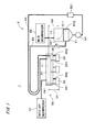
- FIG. 1 is a view showing a construction of part of a printer 1, illustrating a basic construction of a head unit 33 and an ink circulation mechanism 5. To the ink circulation mechanism in the printer 1, actually, a plurality of head units 33 are connected.
- the head unit 33 comprises a plurality of heads 32 each having a plurality of outlets on its lower surface, a first ink tank 34 storing ultraviolet curable ink above and in the vicinity of the plurality of heads 32, a plurality of ink inlet pipes 351 for causing flow of ink from the first ink tank 34 to the plurality of heads 32, respectively, a manifold main body 36 provided in two tiered structure with the first ink tank 34 above the plurality of heads 32, forming an internal space into which ink flows from the plurality of heads 32 and a plurality of ink outlet pipes 352 connecting the plurality of heads 32 and the manifold main body 36, respectively.
- the ink circulation mechanism 5 comprises a second ink tank 51 storing ink, and the second ink tank 51 is connected to the first ink tank 34 through a supply line 52 and also connected to the plurality of heads 32 through a return line 53, the manifold main body 36 in the head unit 33 and the plurality of ink outlet pipes 352.
- the supply line 52 is provided with a pump 54 and a filter 521, and with the pump 54, ink stored in the second ink tank 51 is supplied to the first ink tank 34 and stored therein while unnecessary substances in the ink are removed through the filter 521.
- the area of cross section in a horizontal plane of the internal space in the second ink tank 51 is almost constant in a vertical direction (the same applies to the first ink tank 34), and the cross-sectional area of the second ink tank 51 is larger than that of the first ink tank 34.
- Long supply line 52 and return line 53 are used to allow the head unit 33 to move in parallel toward the left side in Fig. 1 (the opposite side of the second ink tank 51) in maintenance and the like.
- a main decompressor 55 having a pump, a pressure regulating valve, a pressure gauge and the like is connected, and the main decompressor 55 reduces a pressure (of gas) inside the second ink tank 51 to become a pressure (hereinafter, referred to as a "normal circulation pressure") lower than the atmosphere pressure by several hundred millibar (mbar) (e.g., 500 mbar (i.e., 5 ⁇ 10 4 pascal (Pa))), to thereby return ink from the first ink tank 34 to the second ink tank 51 through a passage (hereinafter, referred to as a "return passage") leading from the first ink tank 34 to the second ink tank 51 via the plurality of ink inlet pipes 351, the plurality of heads 32, the plurality of ink outlet pipes 352, the manifold main body 36 and the return line 53, with the return passage filled with ink.
- mbar millibar
- a passage hereinafter, referred to as a "return passage" leading from
- the return line 53 is provided with a flow regulating valve 531 serving as a flow limiting part to limit the flow of ink from the first ink tank 34 to the second ink tank 51 in accordance with the area of an opening (hereinafter, referred to as a "passage opening") serving as a passage inside the flow regulating valve 531.
- a flow regulating valve 531 serving as a flow limiting part to limit the flow of ink from the first ink tank 34 to the second ink tank 51 in accordance with the area of an opening (hereinafter, referred to as a "passage opening" serving as a passage inside the flow regulating valve 531.
- the main decompressor 55 controls the pressure inside the second ink tank 51 to be almost constant, the flow rate of ink in the heads 32 is made almost constant with time. Further, depending on the design of the printer 1, a thin tube capable of causing the same pressure loss as the flow regulating valve 531 does may be provided as the flow limiting part instead of flow regulating valve 531.
- the flow rate of ink actually, also depends on the position of a liquid surface of ink in the first ink tank 34, since the specific gravity of ink used in the preferred embodiment is almost 1 and variation of the position of the liquid surface of ink is controlled to fall within the range of ⁇ several millimeter (mm) in the printer 1, the variation of the position of the liquid surface of ink corresponds to only pressure variation less than ⁇ 1 mbar. Therefore, the effect of the variation in the position of the liquid surface of ink in the first ink tank 34 on the flow rate of ink is very small, as compared with the pressure variation in the second ink tank 51, enough to be ignored.
- the first ink tank 34 and the second ink tank 51 are provided with ink level sensors 341 and 511, respectively, for each detecting the position of the liquid surface of ink (i.e., ink level).
- ink level sensors 341 and 511 respectively, for each detecting the position of the liquid surface of ink (i.e., ink level).
- set are predetermined preset ink levels (indicated by broken lines L1 and L2, respectively, in Fig. 1 ) and replenishment end levels indicating the upper limits and replenishment start levels indicating lower limits with the respective preset ink levels as center positions.
- ink when the position of the liquid surface of ink becomes equal to or lower than the replenishment start level, ink is replenished (supplied) from the second ink tank 51 by the pump 54, and in the second ink tank 51, when the position of the liquid surface of ink becomes equal to or lower than the replenishment start level, ink is replenished from a main ink tank 56 of Fig. 4 described later.
- the second ink tank 51 is provided with a heater 512 and a temperature sensor (not shown) for heating ink up to a predetermined temperature (e.g., 45 °C) so that the viscosity of ink is reduced to be lower than that in a room temperature.
- a predetermined temperature e.g. 45 °C
- the head 32 is provided with a driver circuit, and the driver circuit is cooled since ink whose temperature is controlled passes the head 32. This reduces the manufacturing cost of the printer 1, as compared with a case of providing a separate cooling mechanism.
- an auxiliary decompressor 37 having a pump, a pressure regulating valve, a pressure gauge and the like is connected, and the auxiliary decompressor 37 reduces a pressure (of gas) inside the first ink tank 34 to become a pressure (hereinafter, referred to as a "normal auxiliary-pressure") lower than the atmosphere pressure by several mbar (in other words, the pressure inside the first ink tank 34 becomes a slightly negative pressure).
- the pressure of ink at the plurality of outlets of each head 32 becomes negative pressure and menisci of ink are formed in the outlets to prevent a leak of ink from the outlets. Since the pressure loss (passage resistance) in the ink inlet pipe 351 which is a passage between the first ink tank 34 and the head 32 is much smaller than that of the passage between the head 32 and the second ink tank 51, the negative pressure in the second ink tank 51 has almost no effect on the pressure of ink at the outlets.
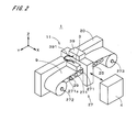
- Fig. 2 is a perspective view showing an appearance of the printer 1.
- the printer 1 performs color printing on a sheet-like liquid-repellent base material 9 such as film in an inkjet manner.
- the ink circulation mechanism 5 is not shown.
- the printer 1 of Fig. 2 comprises a main body 11 and a control part 4, and the main body 11 comprises a feeder 27 for moving the sheet-like base material 9 in the Y direction (hereinafter, referred to also as "scan direction") of Fig. 2 and an ejection part 3 for ejecting fine droplets of ink onto the base material 9 while the base material 9 is being moved by the feeder 27.
- a plurality of rollers 271 each of which is long in the X direction of Fig.
- a supplying part 272 for holding a roll-like base material 9 (feed roll) is provided and on the (-Y) side of the plurality of rollers 271, a winding part 273 for holding a roll-like base material 9 (wind-up roll) is provided.
- the base material 9 when simply referred to as the base material 9, it refers to a part of the base material 9 which is being moved (in other words, a part of the base material 9 which is positioned on the plurality of rollers 271).
- One of the rollers, 271a, in the feeder 27 is provided with an encoder 29 for detecting a movement speed of the base material 9 in the scan direction, and the control part 4 controls the rotation of a motor of the winding part 273 on the basis of an output of the encoder 29, to thereby move the base material 9 in the (-Y) direction at a constant speed.
- a motor of the supplying part 272 gives a load (tension) in a direction opposite to a moving direction (i.e., in the (+Y) direction) to the base material 9, to thereby smoothly move the base material 9 on the plurality of rollers 271 without waving.
- the ejection part 3 is disposed above the plurality of rollers 271 (on the (+Z) side of Fig. 2 ) and fixed onto a frame 25 provided on a base 20, being across the plurality of rollers 271.
- a light source 39 for emitting ultraviolet rays is provided and light emitted from the light source 39 is led into the ejection part 3 through a plurality of optical fibers (actually, the plurality of optical fibers are made into a bundle and indicated by one thick line with reference numeral 391 in Fig. 2 ).
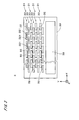
- Fig. 3 is a bottom plan view showing the ejection part 3.
- the ejection part 3 comprises a plurality of head groups 31 (four head groups 31 in Fig. 3 ) for ejecting ink of different colors, and the plurality of head groups 31 are arranged in the Y direction and fixed to a body 30 of the ejection part 3.
- the plurality of head groups 31 are arranged in the Y direction and fixed to a body 30 of the ejection part 3.
- the first head group 31 on the (+Y) side ejects ink of K (black), the head group 31 adjacent to the head group 31 of K on the (-Y) side ejects ink of C (cyan), the head group 31 adjacent to the head group 31 of C on the (-Y) side ejects ink of M (magenta) and the first head group 31 on the (-Y) side ejects ink of Y (yellow).
- the ink of each color includes an ultraviolet curing agent and is ultraviolet curable.
- the ejection part 3 may be further provided with head groups 31 of other colors, e.g., light cyan, light magenta, white and the like.
- the plurality of heads 32 are arranged in a staggered manner in the X direction (a direction orthogonal to the Y direction and the Z direction, and hereinafter, referred to as a "width direction") in Fig. 3 , and in each of the heads 32, the plurality of outlets (the outlets in some heads 32 are represented by dots with reference numeral 321) are formed and arranged in the width direction.
- a lot of outlets 321 are arranged at a constant pitch in the width direction which is an arrangement direction, to thereby allow formation of a plurality of dots aligned in the width direction at each position on the base material 9 in the scan direction.
- the plurality of outlets 321 in each of the head groups 31 are provided entirely in a printing area on the base material 9 with respect to the width direction (herein, almost entirely in the width in the width direction of the base material 9), and with only one pass of the base material 9 below the ejection part 3, printing of an image on the base material 9 is completed (so-called one-pass printing).
- a light emitting part 38 connected to the light source 39 is provided on the (-Y) side of the plurality of head groups 31.
- a plurality of optical fibers are arranged along the X direction and ultraviolet rays are emitted from the light emitting part 38 onto a linear area extending in the X direction on the base material 9.
- the plurality of heads 32 aligned in the width direction constitute one head unit 33 and the plurality of head units 33 (two head units 33 in Fig. 3 ) are arranged in the scan direction, to form an arrangement of heads 32 in each head group 31.
- the plurality of head units 33 are connected in parallel to the ink circulation mechanism 5 (see Fig. 4 discussed later), and with the ink circulation mechanism 5, ink is supplied to the plurality of heads 32 in each head unit 33 and returned from the head unit 33.
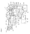
- Fig. 4 is a view showing a construction of the head units 33 and the ink circulation mechanism 5.
- the printer 1 is provided with the plurality of head units 33 (two head units 33 are shown in Fig. 4 , and one of the head units 33 is simply represented by a rectangle).
- the ink circulation mechanism 5 has the second ink tank 51 storing ink, to which the supply line 52 and the return line 53 are connected.
- One side of the supply line 52 opposite to the second ink tank 51 branches into a plurality of supply branch lines 520 which are connected to the first ink tanks 34 of the plurality of head units 33, respectively and each of the supply branch lines 520 is provided with a valve 523.
- a filter 521 and a deaerator 522 are provided between a branch point of the supply line 52 and the pump 54.
- one side of the return line 53 opposite to the second ink tank 51 also branches into a plurality of return branch lines 530 and the plurality of return branch lines 530 are connected to the respective manifold main bodies 36 of the plurality of head units 33.
- Each of the return branch lines 530 is provided with the flow regulating valve 531 and a flow measurement part 532 for measuring the flow rate of ink.
- the respective flow rates of ink in the plurality of return branch lines 530 are set equal.
- a valve hereinafter, referred to as a "return line valve” 533 is provided in the vicinity of the second ink tank 51.
- auxiliary passage 552 used for an initial installation of ink discussed later.
- the other end of the auxiliary passage 552 branches into a plurality of auxiliary branch passages 553 and the plurality of auxiliary branch passages 553 are connected to the plurality of return branch lines 530, respectively.
- an uppermost part of each of the return branch lines 530 is positioned upper than the liquid surface of ink stored in the first ink tank 34 and the auxiliary branch passage 553 is connected to the uppermost part or in the vicinity thereof.
- each of the auxiliary branch passage 553 is provided with a valve 554.
- the main ink tank 56 is further connected via a valve 561, and ink is replenished into the second ink tank 51 from the main ink tank 56 as necessary.
- auxiliary decompressor 37 To the auxiliary decompressor 37 connected is one end of a decompression pipe 371, and the other end of the decompression pipe 371 branches into a plurality of pipes which are connected to the respective first ink tanks 34 in the plurality of head units 33.
- a first switching valve 372 is provided between the auxiliary decompressor 37 and the branch point in the decompression pipe 371 and this makes the first ink tanks 34 connectable to either a passage connected to the auxiliary decompressor 37 or another passage.
- a second switching valve 373 In another passage, a second switching valve 373 is provided and this makes it possible to switch between a passage which is open to the air through a filter 374 and a passage connected to a compressed air source 376 through a regulator 375.
- the first ink tank 34 is in any one of the states where being connected to the auxiliary decompressor 37, the inside thereof is decompressed, where being connected to the filter 374, a pressure inside it is brought into the atmosphere pressure and where being connected to the compressed air source 376, the inside thereof is pressurized.
- the compressed air source 376 has a pump and a filter, and compressed air from the compressed air source 376 is regulated by the regulator 375 to such a pressure as not to damage the outlets of the heads 32.
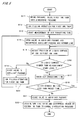
- Fig. 5 is a flowchart showing an operation flow of initially installing ink into the printer 1.
- Step S11 a pressure inside the first ink tanks 34 is brought into the atmosphere pressure (Step S11) and subsequently performed is an operation of filling the first ink tanks 34 with ink (Step S12).
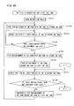
- Figs. 6A and 6B are flowcharts showing a flow of ink filling operation for the first ink tanks 34, which is the operation performed in Step S12 of Fig. 5 .
- the return line valve 533 provided between the flow regulating valve 531 and the second ink tank 51 in the return line 53 is closed (Step S121), and subsequently, the main decompressor 55 decompresses the inside of the second ink tank 51 to a predetermined pressure (e.g., the normal circulation pressure) and a valve 561 provided between the main ink tank 56 and the second ink tank 51 is opened.
- a predetermined pressure e.g., the normal circulation pressure
- Step S122 ink stored in the main ink tank 56 moves to the second ink tank 51 and replenishment of ink from the main ink tank 56 to the second ink tank 51 is started (Step S122).
- the return line valve 533 is provided in the vicinity of the second ink tank 51, a part of the return line 53 which is positioned between the return line valve 533 and the second ink tank 51 is filled with ink. In other words, the air existing in this part moves into the second ink tank 51.
- the position of the liquid surface of ink in the second ink tank 51 is repeatedly detected on the basis of an output from the ink level sensor 511 of the second ink tank 51 (Steps S123 and S124), and when it is found that the liquid surface of ink reaches the replenishment end level higher than the preset ink level L2 (Step S124), the valve 561 is closed, decompression of the second ink tank 51 by the main decompressor 55 is stopped, and then the pressure inside the second ink tank 51 is made the atmosphere pressure. With this, replenishment of ink from the main ink tank 56 to the second ink tank 51 is finished (Step S125).
- Step S126 the respective valves 523 of the plurality of supply branch lines 520 are opened and driving of the pump 54 is started.
- the ink stored in the second ink tank 51 moves to the respective first ink tanks 34 of the plurality of head units 33 through the supply line 52 and replenishment of ink from the second ink tank 51 to the first ink tanks 34 is started (Step S126).
- the respective valves 554 of the plurality of auxiliary branch passages 553 are opened, the ink in the first ink tank 34 of each head unit 33 is filled through the plurality of ink inlet pipes 351 (in Fig.
- reference numeral 351 is given only to one ink inlet pipe and reference numeral 352 is given only to one ink outlet pipe
- the plurality of heads 32, the plurality of ink outlet pipes 352 up to the manifold main body 36 and a liquid surface of ink is formed at the same level as the liquid surface of ink in the first ink tank 34 at a part of the return branch line 530 extending upward from the manifold main body 36 in the vertical direction.
- a dedicated receiver is provided below the head unit 33 and therefore no problem arises even if ink runs from the outlets.
- Step S127 the position of the liquid surface of ink in the second ink tank 51 provided below is detected on the basis of an output from the ink level sensor 511 (Step S127), and when it is found that the liquid surface of ink is higher than the replenishment start level which is positioned lower than the preset ink level L2 (Step S128), the position of the liquid surface of ink in the first ink tank 34 provided above is detected on the basis of an output from the ink level sensor 341 of the first ink tank 34 (Step S129).
- Step S130 When it is found that the liquid surface of ink is lower than the replenishment end level which is positioned higher than the preset ink level L1 (Step S130), the position of the liquid surface of ink in the second ink tank 51 is detected again (Step S127). Thus, while the replenishment of ink to the first ink tank 34 is performed, the operations of Steps S127 to S130 are repeated.
- Step S127 and S1208 when it is found that the height of the liquid surface of ink in the second ink tank 51 becomes equal to or lower than the replenishment start level by the movement (flow) of ink from the second ink tank 51 to the first ink tank 34 (Steps S127 and S128), the valves 523 of the plurality of supply branch lines 520 are temporarily closed and the pump 54 is stopped and this temporarily stops the replenishment of ink from the second ink tank 51 to the first ink tank 34 (Step S131).
- Step S122 to S125 ink is replenished from the main ink tank 56 to the second ink tank 51 and after that, the supply of ink from the second ink tank 51 to the first ink tank 34 is resumed (Step S126) and the operations of Steps S127 to S130 are repeated.
- Step S129 and S130 when it is found that the liquid surface of ink in the first ink tank 34 of each head unit 33 reaches the replenishment end level (Step S129 and S130), the valves 523 of the plurality of supply branch lines 520 are closed and the pump 54 is stopped and this stops the replenishment of ink from the second ink tank 51 to the first ink tank 34 (Step S132).
- Step S13 the control part 4 starts to measure the time (the air exhausting time discussed later) (Step S13), and at the same time, the valves 554 of the plurality of auxiliary branch passages 553 are opened and the main decompressor 55 starts decompression.
- the inside of the auxiliary passage 552 including the auxiliary branch passages 553 and the inside of the return line 53 including the return branch lines 530 are decompressed and ink flows into the return line 53 (Step S14).
- the plurality of auxiliary branch passages 553 are provided so as to extend upward from respective uppermost parts of the plurality of return branch lines 530 in the vertical direction, and the plurality of valves 554 are disposed at the same level, and the main decompressor 55 decompresses the inside of the second ink tank 51 and the auxiliary passage 552 to an initial installation pressure so that the liquid surface of ink may be formed above the open/close position of the valve 554 in each auxiliary branch passage 553 (in other words, the position to open or close a passage inside the valve 554).
- the specific gravity of the ink used in this preferred embodiment is almost 1 and the pressure in the first ink tank 34 is brought into the atmosphere pressure by the operation of Step S11, when the difference in height in the vertical direction between the position of liquid surface formed in the auxiliary branch passage 553 and the position of the liquid surface in the first ink tank 34 (indicated by an arrow D3 in Fig. 4 ) is ⁇ cm, the initial installation pressure in the auxiliary passage 552 is lower than the atmosphere pressure by ⁇ mbar. Further, the initial installation pressure is sufficiently higher than the normal circulation pressure.
- Step S15 When the position of the liquid surface of ink in the first ink tank 34 is detected (Step S15) and it is found that the liquid surface of ink is higher than the replenishment start level lower than the preset ink level L1 (Step S16), the control part 4 checks the time period after the time measurement is started in Step S13 (in other words, the time period after the decompression of the auxiliary passage 552 and the return line 53 is started and hereinafter, referred to as "air exhausting time") (Step S17), and if the air exhausting time is shorter than a preset time which is set in advance (Step S18), back to Step S15, the position of the liquid surface of ink in the first ink tank 34 is detected.
- the check of the position of the liquid surface of ink in the first ink tank 34 and the comparison between the air exhausting time and the preset time are repeatedly performed (Steps S15 to S18).
- Step S15 and S16 the valves 554 of the plurality of auxiliary branch passages 553 are temporarily closed (Step S19) and the ink filling operation for the first ink tank 34 like in Step S12 is performed (Step S20) (unnecessary operations, however, may be omitted as appropriate). Then, when the first ink tank 34 is filled with ink, the valves 554 of the plurality of auxiliary branch passages 553 are opened again and the inside of the auxiliary passage 552 and the inside of the return line 53 are decompressed (Step S14), and the operations of Steps S15 to S18 are repeated. Further, while the valves 554 of the auxiliary branch passages 553 are closed, the measurement of the air exhausting time is temporarily stopped.
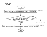
- Step S21 when the air exhausting time equals or exceeds the preset time (Steps S17 and S18), the valves 554 of the plurality of auxiliary branch passages 553 are closed (Step S21).
- the inside of the auxiliary passage 552 is decompressed to the initial installation pressure and the state where the liquid surface of ink is formed in each auxiliary branch passage 553 continues for some time, and this evacuates air from the part of the return line 53 which leads from the first ink tank 34 to the return line valve 533 so that the part is filled with ink.
- the initial installation pressure is slightly lower than the atmosphere pressure (in other words, a low negative pressure)
- meniscus of ink is formed at each outlet of the head 32 and no air flows from the outlet into the head 32.
- Step S22 the movement (flow) of ink into the second ink tank 51 from the first ink tanks 34 of the head units 33 starts and the initial installation of ink is completed.
- Step S22 even if air remains in the part of the return line 53 which is positioned between the return line valve 533 and the second ink tank 51, this air flows into the second ink tank 51 together with the ink.
- the auxiliary decompressor 37 decompresses the inside of each first ink tank 34 to the normal auxiliary-pressure.
- Fig. 7 is a flowchart showing an operation flow of ink circulation in the printer 1.
- Step S31 the auxiliary decompressor 37 brings the pressure inside each first ink tank 34 into the normal auxiliary-pressure.
- Step S32 and S33 the position of the liquid surface of ink in the first ink tank 34 is repeatedly detected on the basis of the output from the ink level sensor 341 (Steps S32 and S33). Then, when it is found that the liquid surface of ink becomes equal to or lower than the replenishment start level by the movement of ink from the first ink tank 34 to the second ink tank 51 (Step S33), the driving of the pump 54 is started in a state where the valves 523 of the plurality of supply branch lines 520 are opened, and the ink stored in the second ink tank 51 is supplied to the first ink tanks 34 of the plurality of head units 33 through the supply line 52.
- Step S35 and S36 the position of the liquid surface of ink in the first ink tank 34 is repeatedly detected and when it is found that the liquid surface of ink reaches the replenishment end level (Step S36), the pump 54 is stopped and the replenishment of ink to the first ink tank 34 is completed (Step S37).
- the pump 54 is driven to replenish ink to the first ink tank 34 (Steps S34 to S37) every time when the liquid surface of ink in the first ink tank 34 becomes equal to or lower than the replenishment start level (Steps S38, S32 and S33). Further, in the printer 1, concurrently with the repeated execution of Steps S32 to S37 (Step S38), while the base material 9 is moved in the scan direction, ejection of ink from the plurality of head units 33 is controlled, to perform printing.
- the position of the liquid surface of ink is detected on the basis of the output from the ink level sensor 511, and when the liquid surface of ink becomes equal to or lower than the replenishment start level, ink is replenished from the main ink tank 56 to the second ink tank 51.
- Step S38 if it is intended to stop the ink circulation (Step S38), by closing the return line valve 533 and making the inside of the second ink tank 51 open to the air, the movement of ink from the first ink tank 34 to the second ink tank 51 is stopped (Step S39). Further, when it is intended to drive the printer 1 again after the printer 1 is stopped, the initial installation of ink shown in Fig. 5 may be performed in the state where the first ink tanks 34, the second ink tank 51 and the heads 32 are filled with ink, to remove the air bubbles and the like caused in the return line 53 while the printer 1 is stopped.
- ink stored in the second ink tank 51 is supplied to the first ink tank 34 through the supply line 52, and with the inside of the second ink tank 51 decompressed to the negative pressure, the ink is returned from the first ink tank 34 to the second ink tank 51 through the return line 53.
- the negative pressure inside the second ink tank 51 is used to efficiently degas the ink in the second ink tank 51 and this prevents a trouble in ejection of ink, such as ejection failure caused by the presence of air bubbles in ink in the heads 32.
- the pressure inside the second ink tank 51 is kept almost constant, it is possible to keep the flow rate of ink flowing in the heads 32 (almost) constant, and this suppresses the variation in loss of pressure in the passage leading from the first ink tank 34, in which the pressure is made the normal auxiliary-pressure, to the vicinity of the outlets of the heads 32, to thereby allow the pressure (static pressure) of ink at the outlets of the heads 32 to be kept constant.
- the state of menisci of ink at the outlets becomes stable, to suppress the variation of the landing positions on the base material 9 and the like of ink with respect to the outlets, and it is thereby possible to realize printing of an image on the base material 9 with high precision.
- the ink circulation mechanism 5 of Fig. 4 since the plurality of head units having the same construction are connected in parallel to the supply line 52 and the return line 53, the flow rates of ink are almost equalized in the heads 32 in all the head units 33 to print an image with high precision, and as compared with the comparative example of printer, it is possible to simplify the construction of the printer 1, increase the availability of the printer 1 and reduce the manufacturing cost of the printer 1.
- the printer 1 since the area of the liquid surface in the second ink tank 51 is made larger than that of the liquid surface in the first ink tank 34, it is possible to efficiently perform degassing of ink in the second ink tank 51 with a great negative pressure (a pressure sufficiently lower than the atmosphere pressure) and to suppress dissolution of air into ink in the first ink tank 34.
- a great negative pressure a pressure sufficiently lower than the atmosphere pressure
- the first ink tank(s) 34 gets connected to the compressed air source 376 with the first and second switching valves 372 and 373 and the inside of the first ink tank 34 is thereby pressurized to forcedly eject ink from the outlets in the plurality of heads 32.
- Fig. 8 is a view showing the vicinity of the first ink tank 34.
- an end portion of the supply line 52 on one side opposite to the second ink tank 51 is disposed in the vicinity of a bottom surface (lower surface) inside the first ink tank 34 so that ink flowing into the first ink tank 34 from the second ink tank 51 may remain at a position away from the liquid surface.
- an end portion of the ink inlet pipe 351 (only one ink inlet pipe 351 is shown in Fig. 8 ) on one side opposite to the head 32 is connected to the bottom surface of the first ink tank 34.
- Fig. 9 is a view showing the vicinity of the second ink tank 51.
- an end portion of the return line 53 on one side opposite to the head 32 is open upward so as to face the liquid surface in ink inside the second ink tank 51 and this causes the ink flowing into the second ink tank 51 from the head 32 to go toward the liquid surface and to be agitated in the second ink tank 51.
- the flow of ink in the second ink tank 51 is indicated by a broken arrow with reference sign A2.
- the second ink tank 51 is provided with the heater 512 and the temperature sensor 513, and with the agitation of ink, the temperature of ink in the second ink tank 51 is equalized. Further, with the agitation of ink, it is possible to efficiently perform degassing of ink with the great negative pressure (i.e., the pressure sufficiently lower than the atmosphere pressure) in the second ink tank 51, as compared with the case where ink remains in the vicinity of the liquid surface in the second ink tank 51.
- An end portion of the supply line 52 on one side opposite to the first ink tank 34 is connected to the bottom surface of the second ink tank 51.
- the first ink tank 34 of Fig. 8 causes the ink containing relatively much air to remain in the vicinity of the liquid surface, to thereby suppress the dissolution of air into ink
- the second ink tank 51 of Fig. 9 promotes the degassing of ink with the agitation of ink. Therefore, in cooperation with the technique where the area of the liquid surface of ink in the second ink tank 51 is made larger than that of the liquid surface of ink in the first ink tank 34, it is possible to further suppress the dissolution of air into ink in the first ink tank 34 and to further promote the degassing of ink in the second ink tank 51.
- the negative pressure in the second ink tank 51 is made larger (i.e., the pressure in the second ink tank 51 is made lower) in the normal operation to thereby always perform active degassing of ink in the second ink tank 51
- th negative pressure in the second ink tank 51 is made relatively small in the normal operation and the negative pressure in the second ink tank 51 is made larger regularly or nonregularly, to thereby perform active degassing.
- Fig. 10 is a flowchart showing an operation flow of degassing in the printer 1.
- the pressure inside the second ink tank 51 of Fig. 4 is made higher than that in the above exemplary normal operation (e.g., a pressure lower than the atmosphere pressure by 100 mbar), to thereby return ink from the first ink tank 34 to the second ink tank 51 through the return passage, and the area of the passage opening in the flow regulating valve 531 (the area of a surface perpendicular to the passage) is made larger, to thereby ensure the same flow of ink as that in the above exemplary operation.
- the control part 4 checks if an instruction of degassing given by an operator through an input part is received (Step S41) while performing the normal operation to circulate ink, and if the instruction is not received (Step S42), the number of operations performed to replenish ink from the main ink tank 56 to the second ink tank 51 after the immediately preceding degassing (hereinafter, referred to as "the number of replenishment operations after degassing") is checked (Step S43).
- Step S44 If the number of replenishment operations after degassing is less than a preset number which is set in advance (Step S44), the elapsed time from the immediately preceding degassing (hereinafter, referred to as "the elapsed time after degassing") is checked (Step S45) and if the elapsed time after degassing is less than a predetermined preset time (Step S46), back to Step S41, it is checked whether the instruction by the operator is given or not.
- the elapsed time after degassing the elapsed time after degassing
- Step S42 the operations of Steps S41 to S46 are repeated concurrently with the normal operation, and if the instruction of degassing given by the operator is received (Step S42), if the number of replenishment operations after degassing is equal to or more than the preset number (Step S44) and if the elapsed time after degassing is equal to or more than the preset time (Step S46), the inside of the second ink tank 51 is decompressed to a pressure lower than the atmosphere pressure by e.g., 500 mbar (Step S47). At that time, by narrowing the passage opening in the flow regulating valve 531 (in other words, making the area of the passage opening smaller), the same flow rate as that in the normal operation can be ensured.
- Step S48 the pressure inside the second ink tank 51 is returned to a pressure in the normal operation and the area of the passage opening in the flow regulating valve 531 is also returned to an area in the normal operation. Then, the number of replenishment operations after degassing is reset to 0 and the elapsed time after degassing is also reset to 0 (Step S49). In the printer 1, the operations of Steps S41 to S49 are repeated concurrently with the normal operation and the degassing in the second ink tank 51 (i.e., the operation of Step S47) is performed regularly or nonregularly.
- the main decompressor 55 to decompress the inside of the second ink tank 51 to a pressure lower than that in the normal operation and further narrowing the opening serving as a passage inside the flow regulating valve 531, it is possible to keep the flow rate of ink from the first ink tank 34 to the second ink tank 51 almost constant in the normal operation and the degassing operation while efficiently degassing ink in the second ink tank 51 in the degassing operation and the temperature of the heads 32 and that of ink in the heads 32 can be kept constant, to appropriately perform ejection of ink.
- the flow of ink is kept constant by narrowing the area of the opening of the return line valve 533 in the degassing operation to be smaller than that in the normal operation, and in this case, it can be thought that the return line valve 533 serves as a flow limiting part.
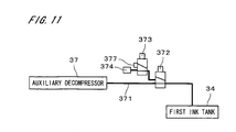
- Fig. 11 is a view showing part of another exemplary printer, i.e., a mechanism relating to the change of the pressure in the first ink tank 34.
- a sealing member 377 is provided, instead of the compressed air source 376, in the passage which is connected to the compressed air source 376 in the printer 1 of Fig. 4 .
- Constituent elements in the printer of Fig. 11 other than those shown in Fig. 11 are identical to those of the printer 1 of Fig. 4 and represented by the same reference signs.
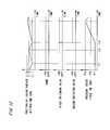
- the pump 54 For forced ejection of ink from the outlets, at the time T3 when the position of the liquid surface of ink in the first ink tank 34 next becomes equal to or lower than the replenishment start level L11, the pump 54 is turned on and both the first and second switching valves 372 and 373 are turned on to seal the first ink tank 34 (except the supply line 52 and the plurality of ink inlet pipes 351) (see Fig. 4 ). Then, the driving of the pump 54 continues until the position of the liquid surface of ink in the first ink tank 34 reaches a predetermined level L 13 higher than the replenishment end level L12.
- both the first and second switching valves 372 and 373 are turned off to connect the first ink tank 34 to the auxiliary decompressor 37 and the on/off of the pump 54 is controlled in accordance with the position of the liquid surface of ink, whether the replenishment start level L11 or the replenishment end level L12.
- the first and second switching valves 372 and 373 and the sealing member 377 serve as a sealing part to seal the first ink tank(s) 34 and ink is supplied into the first ink tank 34 by the pump 54 so that the amount of ink in the first ink tank 34 increases as compared with the normal operation.
- this operation it is possible to easily perform the forced ejection of ink from the plurality of outlets without the compressed air source 376 and the regulator 375 shown in Fig. 4 and to reduce the manufacturing cost for the printer.
- the pump 54 is turned on from the time when the position of the liquid surface of ink in the first ink tank 34 becomes equal to or lower than the replenishment start level L11, to thereby supply ink into the first ink tank 34 up to the level L13 for the forced ejection of ink from the outlets, naturally, the pump 54 may be driven from the state where the ink level is higher than the replenishment start level L11, to forcedly eject ink.
- the second ink tank 51 is disposed at a position lower than the first ink tank 34 in the printer 1 of Fig. 4 (see the second ink tank 51 indicated by the two-dot chain line in Fig. 13 ), the second ink tank 51 may be disposed at a position higher than the first ink tank 34, like in an ink circulation mechanism 5a of Fig. 13 . Also in the ink circulation mechanism 5a of Fig. 13 , an uppermost part of the return line 53 is positioned upper than the liquid surface of ink in the first ink tank 34 and between the heads 32 and the return line valve 533 in the return line 53 and one end of the auxiliary passage 552 is connected to the uppermost part (or in the vicinity of the uppermost part).
- the ink circulation mechanism 5a of Fig. 13 in filling the return passage leading from the first ink tank 34 to the second ink tank 51 via the heads 32 with ink, like in the ink circulation mechanism 5 of Fig. 4 , after the first ink tank 34 is filled with ink, with the return line valve 533 closed, the inside of the auxiliary passage 552 is decompressed so that the liquid surface of ink may be formed upper than the open/close position of the valve 554 in the auxiliary passage 552 (in other words, so that the liquid surface of ink may be formed at a position upper than the position of the liquid surface of ink in the first ink tank 34 by the height indicated by an arrow D4 of Fig.
- the passage filling part is activated with the return line valve 533 closed and ink is caused to flow into the auxiliary passage 552, to thereby fill a part of the return passage which leads from the first ink tank 34 to the return line valve 533 with ink, and after that, the passage filling part is inactivated to close the auxiliary passage 552 at the position where the ink exists, and the return line valve 533 is opened and the main decompressor 55 is driven, to thereby fill the whole of the return passage with ink.
- An ink circulation performed in the ink circulation mechanism 5a is the same as that performed in the ink circulation mechanism 5 of Fig. 4 .
- the pump 54 is driven to supply the first ink tank 34 with ink stored in the second ink tank 51, and the inside of the second ink tank 51 is decompressed to the negative pressure and ink is returned from the first ink tank 34 to the second ink tank 51.
- the pump 54 is driven to supply the first ink tank 34 with ink stored in the second ink tank 51, and the inside of the second ink tank 51 is decompressed to the negative pressure and ink is returned from the first ink tank 34 to the second ink tank 51.
- a mechanism for moving the ejection part 3 in the scan direction may be provided in the printer 1.
- a stage 21 for holding the rectangular base material 9 and a stage moving mechanism 22 for moving the stage 21 in the scan direction may be provided.
- a scan mechanism for moving the base material 9 relatively to the ejection part 3 in the scan direction can be realized.
- the position of the stage 21 relative to the base 20 can be detected by a position detecting module 23 provided on the base 20.
- Photocurable ink used in the printer may be one having the curability to light in a wavelength range other than the ultraviolet rays. In such a case, the light emitted from the light emitting part 38 includes this wavelength range.
- the printing medium used in the printer 1 may be a plate-like member which is formed of plastic, printing paper and the like, other than the sheet-like base material 9.
Landscapes
- Ink Jet (AREA)
Applications Claiming Priority (1)
| Application Number | Priority Date | Filing Date | Title |
|---|---|---|---|
| JP2008137482A JP2009285837A (ja) | 2008-05-27 | 2008-05-27 | 印刷装置、インク循環方法およびインク初期導入方法 |
Publications (1)
| Publication Number | Publication Date |
|---|---|
| EP2127883A1 true EP2127883A1 (en) | 2009-12-02 |
Family
ID=40943874
Family Applications (1)
| Application Number | Title | Priority Date | Filing Date |
|---|---|---|---|
| EP09006830A Withdrawn EP2127883A1 (en) | 2008-05-27 | 2009-05-20 | Printer, ink circulation method and initial ink installation method |
Country Status (3)
| Country | Link |
|---|---|
| US (1) | US20090295881A1 (enExample) |
| EP (1) | EP2127883A1 (enExample) |
| JP (1) | JP2009285837A (enExample) |
Cited By (8)
| Publication number | Priority date | Publication date | Assignee | Title |
|---|---|---|---|---|
| EP2138239A4 (en) * | 2007-04-11 | 2010-06-02 | Musashi Engineering Inc | INK JET HEAD AND INK JET DEVICE |
| EP2468512A1 (en) * | 2010-12-27 | 2012-06-27 | Fuji Xerox Co., Ltd. | Liquid circulating apparatus, computer-readable medium, and liquid discharging apparatus |
| ITMI20111034A1 (it) * | 2011-06-08 | 2012-12-09 | Telecom Italia Spa | Dispositivo per la stampa a getto d'inchiostro di una superficie |
| ITUD20130154A1 (it) * | 2013-11-20 | 2015-05-21 | Neolt S P A In Concordato Preventi Vo | Apparato di stampa e relativo procedimento |
| EP2905142A3 (en) * | 2014-02-07 | 2015-12-16 | Seiko Epson Corporation | Liquid ejecting apparatus |
| DE102016106011A1 (de) * | 2016-04-01 | 2017-10-05 | Till Gmbh | Vorrichtung und Verfahren zur Tintenversorgung beim Digitaldruck |
| EP3424726A1 (en) * | 2017-07-07 | 2019-01-09 | Canon Kabushiki Kaisha | Inkjet printing apparatus and control method of the inkjet printing apparatus |
| EP4000934A1 (en) * | 2020-11-20 | 2022-05-25 | Canon Kabushiki Kaisha | Recording apparatus and method of controlling the same |
Families Citing this family (21)
| Publication number | Priority date | Publication date | Assignee | Title |
|---|---|---|---|---|
| JP5350820B2 (ja) * | 2009-01-30 | 2013-11-27 | 理想科学工業株式会社 | インクジェットプリンタ、及びインク循環方法 |
| JP4869373B2 (ja) * | 2009-03-25 | 2012-02-08 | 株式会社東芝 | 液体循環ユニット、液体循環装置、液滴噴射塗布装置、及び塗布体の形成方法 |
| JP5443287B2 (ja) * | 2010-06-30 | 2014-03-19 | 株式会社ミヤコシ | インクジェット記録装置のインク供給装置 |
| JP5624812B2 (ja) * | 2010-06-30 | 2014-11-12 | 理想科学工業株式会社 | 画像記録装置 |
| JP5707752B2 (ja) * | 2010-07-06 | 2015-04-30 | セイコーエプソン株式会社 | 液体吐出装置 |
| US8371684B2 (en) * | 2011-01-31 | 2013-02-12 | Videojet Technologies Inc. | Ink mixing system |
| JP5857526B2 (ja) * | 2011-08-23 | 2016-02-10 | セイコーエプソン株式会社 | 液体噴射装置、及び、液体噴射装置のメンテナンス方法 |
| DE102012105423A1 (de) * | 2012-06-22 | 2013-12-24 | Océ Printing Systems GmbH & Co. KG | Anordnung und Verfahren zur Versorgung mindestens eines Druckkopfes mit Tinte bei einem Tintendruckgerät |
| DE202013003547U1 (de) * | 2013-04-16 | 2013-05-15 | Jan Franck | Tintennachfülleinrichtung für eine Druckvorrichtung |
| US20150165782A1 (en) * | 2013-10-21 | 2015-06-18 | Aps Engineering | Digital printing system having a modular and reliable ink delivery system |
| JP6447803B2 (ja) * | 2014-03-19 | 2019-01-09 | セイコーエプソン株式会社 | インクジェット方法、インクジェット装置、及びインクジェット組成物収容体 |
| JP6322101B2 (ja) * | 2014-09-16 | 2018-05-09 | 理想科学工業株式会社 | インクジェット印刷装置 |
| JP6397294B2 (ja) * | 2014-09-29 | 2018-09-26 | 理想科学工業株式会社 | インクジェット印刷装置 |
| WO2016066208A1 (en) | 2014-10-30 | 2016-05-06 | Hewlett-Packard Development Company, L.P. | Inkjet printer with primary and secondary ink tanks |
| CN107107620B (zh) | 2015-04-23 | 2019-03-08 | 惠普发展公司有限责任合伙企业 | 液体容器 |
| JP6593256B2 (ja) * | 2016-06-08 | 2019-10-23 | 株式会社村田製作所 | インクジェット印刷装置 |
| JP6798805B2 (ja) * | 2016-06-29 | 2020-12-09 | セーレン株式会社 | インクジェット記録装置 |
| JP7059041B2 (ja) | 2018-02-23 | 2022-04-25 | キヤノン株式会社 | インクジェット記録装置 |
| CN109940996B (zh) * | 2019-03-23 | 2020-06-12 | 福建长信纸业包装有限公司 | 一种循环墨量提供控制方法 |
| WO2022102058A1 (ja) * | 2020-11-12 | 2022-05-19 | コニカミノルタ株式会社 | インクジェット記録方法及びインクジェット記録装置 |
| WO2024102749A1 (en) * | 2022-11-07 | 2024-05-16 | Heat Source Energy Corp. | Organic rankine cycle decompression heat engine |
Citations (3)
| Publication number | Priority date | Publication date | Assignee | Title |
|---|---|---|---|---|
| WO2000038928A1 (en) | 1998-12-24 | 2000-07-06 | Xaar Technology Limited | Droplet deposition apparatus |
| WO2006064036A1 (en) * | 2004-12-17 | 2006-06-22 | Agfa Graphics Nv | Ink circulation system for inkjet printing |
| JP2006289955A (ja) | 2005-03-15 | 2006-10-26 | Konica Minolta Holdings Inc | インクジェット記録装置 |
Family Cites Families (3)
| Publication number | Priority date | Publication date | Assignee | Title |
|---|---|---|---|---|
| US6343857B1 (en) * | 1994-02-04 | 2002-02-05 | Hewlett-Packard Company | Ink circulation in ink-jet pens |
| JP2005144954A (ja) * | 2003-11-18 | 2005-06-09 | Toshiba Tec Corp | インクジェット装置 |
| KR101306005B1 (ko) * | 2006-09-29 | 2013-09-12 | 삼성전자주식회사 | 잉크순환시스템과 잉크젯 기록장치 및 잉크 순환방법 |
-
2008
- 2008-05-27 JP JP2008137482A patent/JP2009285837A/ja not_active Abandoned
-
2009
- 2009-05-19 US US12/468,322 patent/US20090295881A1/en not_active Abandoned
- 2009-05-20 EP EP09006830A patent/EP2127883A1/en not_active Withdrawn
Patent Citations (3)
| Publication number | Priority date | Publication date | Assignee | Title |
|---|---|---|---|---|
| WO2000038928A1 (en) | 1998-12-24 | 2000-07-06 | Xaar Technology Limited | Droplet deposition apparatus |
| WO2006064036A1 (en) * | 2004-12-17 | 2006-06-22 | Agfa Graphics Nv | Ink circulation system for inkjet printing |
| JP2006289955A (ja) | 2005-03-15 | 2006-10-26 | Konica Minolta Holdings Inc | インクジェット記録装置 |
Cited By (22)
| Publication number | Priority date | Publication date | Assignee | Title |
|---|---|---|---|---|
| US8262207B2 (en) | 2007-04-11 | 2012-09-11 | Musashi Engineering, Inc. | Ink-jet head and ink-jet device |
| EP2138239A4 (en) * | 2007-04-11 | 2010-06-02 | Musashi Engineering Inc | INK JET HEAD AND INK JET DEVICE |
| EP2468512A1 (en) * | 2010-12-27 | 2012-06-27 | Fuji Xerox Co., Ltd. | Liquid circulating apparatus, computer-readable medium, and liquid discharging apparatus |
| US8449087B2 (en) | 2010-12-27 | 2013-05-28 | Fuji Xerox Co., Ltd. | Liquid circulating apparatus, computer-readable medium, and liquid discharging apparatus |
| CN103826862B (zh) * | 2011-06-08 | 2016-06-08 | 锡克拜控股有限公司 | 喷墨打印装置 |
| ITMI20111034A1 (it) * | 2011-06-08 | 2012-12-09 | Telecom Italia Spa | Dispositivo per la stampa a getto d'inchiostro di una superficie |
| WO2012168913A1 (en) * | 2011-06-08 | 2012-12-13 | Olivetti S.P.A. | Ink- jet printing device |
| CN103826862A (zh) * | 2011-06-08 | 2014-05-28 | 锡克拜控股有限公司 | 喷墨打印装置 |
| US10076907B2 (en) | 2011-06-08 | 2018-09-18 | Sicpa Holding Sa | Device for ink-jet printing a surface |
| US9346305B2 (en) | 2011-06-08 | 2016-05-24 | Sicpa Holding Sa | Device for ink-jet printing a surface |
| ITUD20130154A1 (it) * | 2013-11-20 | 2015-05-21 | Neolt S P A In Concordato Preventi Vo | Apparato di stampa e relativo procedimento |
| EP2875956A1 (en) * | 2013-11-20 | 2015-05-27 | Jet-Set Srl | Printing apparatus and corresponding method |
| US9242475B2 (en) | 2014-02-07 | 2016-01-26 | Seiko Epson Corporation | Liquid ejecting apparatus |
| EP2905142A3 (en) * | 2014-02-07 | 2015-12-16 | Seiko Epson Corporation | Liquid ejecting apparatus |
| DE102016106011A1 (de) * | 2016-04-01 | 2017-10-05 | Till Gmbh | Vorrichtung und Verfahren zur Tintenversorgung beim Digitaldruck |
| US10611171B2 (en) | 2016-04-01 | 2020-04-07 | Dekron Gmbh | Device and method for ink supply in digital printing |
| EP3424726A1 (en) * | 2017-07-07 | 2019-01-09 | Canon Kabushiki Kaisha | Inkjet printing apparatus and control method of the inkjet printing apparatus |
| US10759181B2 (en) | 2017-07-07 | 2020-09-01 | Canon Kabushiki Kaisha | Inkjet printing apparatus and control method of the inkjet printing apparatus |
| US11577522B2 (en) | 2017-07-07 | 2023-02-14 | Canon Kabushiki Kaisha | Inkjet printing apparatus and control method of the inkjet printing apparatus |
| US12083804B2 (en) | 2017-07-07 | 2024-09-10 | Canon Kabushiki Kaisha | Inkjet printing apparatus and control method of the inkjet printing apparatus |
| EP4000934A1 (en) * | 2020-11-20 | 2022-05-25 | Canon Kabushiki Kaisha | Recording apparatus and method of controlling the same |
| US11840078B2 (en) | 2020-11-20 | 2023-12-12 | Canon Kabushiki Kaisha | Recording apparatus and method of controlling the same |
Also Published As
| Publication number | Publication date |
|---|---|
| US20090295881A1 (en) | 2009-12-03 |
| JP2009285837A (ja) | 2009-12-10 |
Similar Documents
| Publication | Publication Date | Title |
|---|---|---|
| EP2127883A1 (en) | Printer, ink circulation method and initial ink installation method | |
| JP5614095B2 (ja) | 液体噴射装置 | |
| JP5163286B2 (ja) | 液体吐出装置及び画像投射装置 | |
| JP5299179B2 (ja) | 画像形成装置 | |
| JP5257139B2 (ja) | 画像形成装置 | |
| CN104441978B (zh) | 液体喷射装置及加减压方法 | |
| JP5471599B2 (ja) | 画像形成装置 | |
| JP7095243B2 (ja) | 液体吐出装置および液体吐出装置の制御方法 | |
| US20140132656A1 (en) | Printhead assembly priming | |
| US20130235100A1 (en) | Liquid-discharging device, liquid stirring method, and liquid filling method | |
| JP5272947B2 (ja) | 画像形成装置 | |
| JP2009285845A (ja) | 印刷装置および印刷方法 | |
| JP5636823B2 (ja) | 画像形成装置 | |
| CN104441998A (zh) | 液体喷射装置以及该液体喷射装置的加减压方法 | |
| US8240832B2 (en) | Head unit and printer | |
| JP2011201176A (ja) | 記録装置および記録方法 | |
| JP2017001342A (ja) | 液体吐出装置及び画像形成装置 | |
| JP2010030206A (ja) | 液体供給装置、液体吐出装置、及び液体吐出装置の制御方法 | |
| JP2010201810A (ja) | 印刷装置および印刷方法 | |
| JP6690380B2 (ja) | 液滴吐出装置及び液滴吐出装置の制御方法 | |
| US20180194143A1 (en) | Liquid supply system and inkjet recording apparatus having the same | |
| JP7116917B2 (ja) | 液体を吐出する装置 | |
| JP5278251B2 (ja) | 画像形成装置 | |
| JP7330832B2 (ja) | 印刷装置および印刷装置における液体循環方法 | |
| JP6897463B2 (ja) | インクジェット記録装置、粘度推定方法、及び、記憶媒体 |
Legal Events
| Date | Code | Title | Description |
|---|---|---|---|
| PUAI | Public reference made under article 153(3) epc to a published international application that has entered the european phase |
Free format text: ORIGINAL CODE: 0009012 |
|
| AK | Designated contracting states |
Kind code of ref document: A1 Designated state(s): AT BE BG CH CY CZ DE DK EE ES FI FR GB GR HR HU IE IS IT LI LT LU LV MC MK MT NL NO PL PT RO SE SI SK TR |
|
| 17P | Request for examination filed |
Effective date: 20100215 |
|
| GRAP | Despatch of communication of intention to grant a patent |
Free format text: ORIGINAL CODE: EPIDOSNIGR1 |
|
| STAA | Information on the status of an ep patent application or granted ep patent |
Free format text: STATUS: THE APPLICATION IS DEEMED TO BE WITHDRAWN |
|
| 18D | Application deemed to be withdrawn |
Effective date: 20130709 |