EP2127498B1 - Auswertevorrichtung für die zündenergie einer entladungslampe - Google Patents
Auswertevorrichtung für die zündenergie einer entladungslampe Download PDFInfo
- Publication number
- EP2127498B1 EP2127498B1 EP08716843A EP08716843A EP2127498B1 EP 2127498 B1 EP2127498 B1 EP 2127498B1 EP 08716843 A EP08716843 A EP 08716843A EP 08716843 A EP08716843 A EP 08716843A EP 2127498 B1 EP2127498 B1 EP 2127498B1
- Authority
- EP
- European Patent Office
- Prior art keywords
- evaluation device
- voltage
- switch
- signal
- discharge lamp
- Prior art date
- Legal status (The legal status is an assumption and is not a legal conclusion. Google has not performed a legal analysis and makes no representation as to the accuracy of the status listed.)
- Not-in-force
Links
- 238000011156 evaluation Methods 0.000 title claims abstract description 23
- 230000010354 integration Effects 0.000 claims description 6
- 238000005259 measurement Methods 0.000 claims description 4
- 238000001514 detection method Methods 0.000 claims description 3
- 239000003990 capacitor Substances 0.000 description 4
- 230000036962 time dependent Effects 0.000 description 4
- 230000015556 catabolic process Effects 0.000 description 2
- DGAQECJNVWCQMB-PUAWFVPOSA-M Ilexoside XXIX Chemical compound C[C@@H]1CC[C@@]2(CC[C@@]3(C(=CC[C@H]4[C@]3(CC[C@@H]5[C@@]4(CC[C@@H](C5(C)C)OS(=O)(=O)[O-])C)C)[C@@H]2[C@]1(C)O)C)C(=O)O[C@H]6[C@@H]([C@H]([C@@H]([C@H](O6)CO)O)O)O.[Na+] DGAQECJNVWCQMB-PUAWFVPOSA-M 0.000 description 1
- 230000001186 cumulative effect Effects 0.000 description 1
- 238000006073 displacement reaction Methods 0.000 description 1
- 238000000034 method Methods 0.000 description 1
- 230000003134 recirculating effect Effects 0.000 description 1
- 230000003252 repetitive effect Effects 0.000 description 1
- 239000000523 sample Substances 0.000 description 1
- 229910052708 sodium Inorganic materials 0.000 description 1
- 239000011734 sodium Substances 0.000 description 1
- 239000007858 starting material Substances 0.000 description 1
Images



Classifications
-
- H—ELECTRICITY
- H05—ELECTRIC TECHNIQUES NOT OTHERWISE PROVIDED FOR
- H05B—ELECTRIC HEATING; ELECTRIC LIGHT SOURCES NOT OTHERWISE PROVIDED FOR; CIRCUIT ARRANGEMENTS FOR ELECTRIC LIGHT SOURCES, IN GENERAL
- H05B41/00—Circuit arrangements or apparatus for igniting or operating discharge lamps
- H05B41/14—Circuit arrangements
- H05B41/26—Circuit arrangements in which the lamp is fed by power derived from DC by means of a converter, e.g. by high-voltage DC
- H05B41/28—Circuit arrangements in which the lamp is fed by power derived from DC by means of a converter, e.g. by high-voltage DC using static converters
- H05B41/288—Circuit arrangements in which the lamp is fed by power derived from DC by means of a converter, e.g. by high-voltage DC using static converters with semiconductor devices and specially adapted for lamps without preheating electrodes, e.g. for high-intensity discharge lamps, high-pressure mercury or sodium lamps or low-pressure sodium lamps
-
- H—ELECTRICITY
- H05—ELECTRIC TECHNIQUES NOT OTHERWISE PROVIDED FOR
- H05B—ELECTRIC HEATING; ELECTRIC LIGHT SOURCES NOT OTHERWISE PROVIDED FOR; CIRCUIT ARRANGEMENTS FOR ELECTRIC LIGHT SOURCES, IN GENERAL
- H05B41/00—Circuit arrangements or apparatus for igniting or operating discharge lamps
- H05B41/02—Details
- H05B41/04—Starting switches
- H05B41/042—Starting switches using semiconductor devices
Definitions
- the invention relates to a device for evaluating the ignition energy of a discharge lamp from a signal which is proportional to the voltage applied to the discharge lamp and a signal which is proportional to the current flowing through the discharge lamp during the ignition process.
- a starter is connected to discharge lamps, in particular high-pressure discharge lamps, for ignition, which generates one or a series of high-voltage pulses in order to ignite the discharge lamp.
- the high voltage pulses must have a certain deviszündbeginnu U Z.
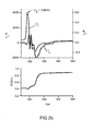
- FIG. 1 shows the time dependent voltage U L (t) generated on a high pressure 400 W sodium vapor lamp with a first ignitor.
- Fig. 2a represents the current and voltage curve of the discharge lamp and the cumulative energy introduced over a wide time range
- the ignition voltage can also be used with a peak voltage detector in be measured in a simple and cost-effective manner.
- FIG. 1 shows the time dependent voltage U L (t) generated on a high pressure 400 W sodium vapor lamp with a first ignitor.
- Fig. 2a represents the current and voltage curve of the discharge lamp and the cumulative energy introduced over a wide time range
- FIG. 2b is shown
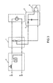
- a peak voltage detector is shown for the evaluation of the positive maximum value of the voltage.
- An analogue-to-digital converter is used for measuring the measurement. If the peak values of each pulse are to be measured for repetitive pulses, it is necessary to recharge the capacitor between the individual pulses, which can be done for example by a high-impedance resistor.
- the knife detection system must also have a sufficiently large acquisition rate. It is possible to use the signals of the peak voltage detector to control an igniter.
- the energy can be used, which is coupled into the discharge during the voltage breakdown.
- the oscilloscope together with the voltage, measures a signal that is proportional to the current.
- I L (t) the current flowing through the lamp current I L (t), in which the displacement current has been compensated, also registered.
- This evaluation device should be suitable that it can be integrated in electronic ballasts or ignitors.
- the object of the invention is to provide a device that meets these requirements.
- the device consists of a voltage measuring circuit (1), a current measuring circuit (2) and an evaluation circuit (4).
- the evaluation circuit the current and voltage signals are multiplied together, and the resulting power signal is then integrated to obtain a measure of the ignition energy.
- This voltage which represents the ignition energy, is measured by a fast analog-to-digital converter.
- Fig. 4 shows the structure of the evaluation device according to the invention.
- the mains voltage is connected to the discharge lamp via a choke (D) and an ignition device (ZG).
- a suitable voltage divider (1) a signal voltage U U is generated.
- a suitable current-voltage converter (2) preferably in the recirculating Line is looped, a signal U I is generated in proportion to the current flowing through the lamp.
- the voltage U U and the current signal U I are connected together with a voltage supply U S to the energy evaluation device (4).
- the voltage signal is connected to an amplifier which drives the input of the threshold detector and the multiplier with a sufficient bandwidth.
- the threshold detector or comparator provides a signal when the applied voltage exceeds a certain threshold.
- the threshold value can be set by means of an adjustable resistor.
- the threshold detector gives the state to a logic board.
- the current signal At the input of the multiplier along with the increased voltage signal U U U I is the current signal connected.
- the output is connected to a load resistor and connected via a fast switch and a resistor to an integration capacitor.
- the logic board after the voltage has exceeded a threshold, turns the fast switch on and off again after a specified time. During this time, the applied power signal is integrated, so that a signal U EZ proportional to the ignition energy is applied to the integration capacitor.
- This signal can be measured by a voltmeter. Since ignitors usually generate a train of pulses with pulse intervals, it is necessary to measure the energies of the individual pulses to use a measuring system that has a sufficiently large Has collection rate.
- the integration capacitor must also be reset, which can be realized by a short-circuit switch.
- This switch may receive its drive signal from the logic board or from the blade detection system.
- the logic subassembly gives a signal with a short time duration to this short-circuit switch after a defined time after which the voltage has exceeded the threshold value.
- This device works independently and can be set up as a separate working system. It is also possible to integrate this evaluation device in an ignitor or in an electronic ballast. For these applications, it is necessary to adapt the times of the logic module to the requirements.
Landscapes
- Circuit Arrangements For Discharge Lamps (AREA)
- Ignition Installations For Internal Combustion Engines (AREA)
Abstract
Description
- Die Erfindung betrifft eine Vorrichtung für die Auswertung der Zündenergie einer Entladungslampe aus einem Signal das proportional der an der Entladungslampe anliegenden Spannung und einem Signal das proportional dem durch die Entladungslampe fließenden Stromes während des Zündvorganges ist.
- An Entladungslampen, insbesondere Hochdruckentladungslampen wird zur Zündung ein Zündgerät angeschlossen, dass ein oder eine Folge von Hochspannungsimpulsen erzeugt, um die Entladungslampe zu zünden. Für eine erfolgreiche Zündung müssen die Hochspannungsimpulse eine gewisse Mindestzündspannung UZ haben.
- Für die Messung der der Hochspannungsimpulses wird üblicherweise ein Hochspannungstastkopf und ein Oszilloskop verwendet. In
Figur 1 wird die an einer 400 W Natriumdampf-Hochdrucklampe mit einem ersten Zündgerät erzeugte zeitabhängige Spannung UL(t) gezeigt. Die Zündspannung UZ ist der Maximalwert der Spannung (UZ = 3.55 kV).Fig. 2a stellt den Strom- und Spannungsverlauf der Entladungslampe und die kumulierte eingebrachte Energie in einem weiten Zeitbereich dar. InFigur 2b ist für ein zweites Zündgerät die zeitabhängige Spannung UL(t) und die ausgewertete Zündspannung UZ (UZ = 3.96 kV) gezeigt. Die Zündspannung kann auch mit einem Spitzenspannungsdetektor in einfacher und kostengünstiger Art und Weise gemessen werden. InFigur 3 ist ein Spitzenspannungsdetektor für die Auswertung des positiven Maximalwertes der Spannung gezeigt. Zur Messerfassung wird ein Analog-Digital-Wandler eingesetzt. Sollen die Spitzenwerte der eines jeden Impulses für wiederholende Impulse gemessen werden, so ist es erforderlich den Kondensator zwischen den einzelnen Impulsen wieder zu entladen, was z.B. durch einen hochohmigen Widerstand erfolgen kann. Das Messerfassungssystem muss zudem eine ausreichend große Erfassungsrate haben. Es ist möglich die Signale des Spitzenspannungsdetektors zur Regelung einer Zündvorrichtung zu benutzen. - Als zweite Messgröße zur Beschreibung der Zündung kann die Energie benutzt werden, die während des Spannungszusammenbruches in die Entladung eingekoppelt wird. Hierzu wird mit dem Oszilloskop zusammen mit der Spannung ein Signal, das proportional des Stromes ist, gemessen. In
Figur 1 undFigur 2a undb ist der durch die Lampe fließende Strom IL(t), bei dem der Verschiebungsstrom kompensiert wurde, ebenfalls mit eingetragen. Als Produkt aus Lampenspannung UL(t) und Strom IL(t) wird die Leistung berechnet:
- Die zeitabhängige Energie wird dann durch die Integration der Leistung PL(t) für die die Zeit t berechnet:
- In
Figur 1 undFigur 2 a ,b sind die Leistung PL(t) und die berechnete zeitabhängige Energie E(t) mit eingetragen. Es ist erkennbar, dass die Energie E (t) nach dem Spannungszusammenbruch und wenn der Strom auf Null zurückgegangen ist auf einen konstanten Wert verbleibt. Da die Hochspannungsimpulse in der Regel innerhalb einer bestimmten Zeit abklingen, ist die Energie die während dieser Zeit eingekoppelt wird die Zündenergie EZ. - Für die Auswertung der Zündenergie beliebiger Entladungslampen soll ein kostengünstiges Messsystem geschaffen werden. Diese Auswertevorrichtung soll geeignet sein, dass es in elektronischen Vorschaltgeräten oder in Zündgeräten integriert werden kann. Die erfindungsgemäße Aufgabe besteht darin eine Vorrichtung zur schaffen, die diesen Anforderungen genügt.
- Die Vorrichtung besteht aus einer Spannungsmesschaltung (1), aus einer Strommessschaltung (2) und aus einer Auswerteschaltung (4). In der Auswerteschaltung werden das Strom- und das Spannungssignal miteinander multipliziert, und das resultierende Leistungssignal dann integriert, um ein Maß für die Zündenergie zu erhalten. Diese Spannung, die die Zündenergie repräsentiert, wird von einem schnellen Analog/Digitalwandler gemessen.
-
- Fig. 1
- Spannung und Strom und die ausgewertete Leistung und Energie eines Hochspannungsimpulses für die Zündung einer Entladungslampe in einer hohen Zeitauflösung.
- Fig. 2a
- Spannung und Strom und die ausgewertete Leistung und Energie eines Hochspannungsimpulses für die Zündung einer Entladungslampe in einer geringeren Zeitauflösung.
- Fig. 2b
- Spannung und Strom und die ausgewertete Leistung und Energie eines Hochspannungsimpulses für die Zündung einer Entladungslampe in einer höheren Zeitauflösung dargestellt in einem bestimmten Bereich.
- Fig. 3
- Aufbau zur Auswertung der positiven Spitzenspannung bei der Zündung einer Entladungslampe.
- Fig. 4
- Aufbau zur Messung der Zündenergie einer Entladungslampe.
-
Fig. 4 zeigt den erfindungsgemäßen Aufbau der Auswertevorrichtung. Die Netzspannung wird über eine Drossel (D) und ein Zündgerät (ZG) an die Entladungslampe angeschlossen. Mit einem geeigneten Spannungsteiler (1) wird eine Signalspannung UU erzeugt. Mit einem geeigneten Strom-Spannungs-Wandler (2), der vorzugsweise in die rückführende Leitung eingeschleift wird, wird ein Signal UI proportional dem durch die Lampe fließenden Stromes erzeugt. - Das Spannungs- UU und das Stromsignal UI werden zusammen mit einer Spannungsversorgung US an die Energieauswertevorrichtung (4) angeschlossen. Das Spannungssignal wird an einem Verstärker angeschlossen, der den Eingang des Schwellenwertdetektors und den Multiplizierer mit einer ausreichenden Bandbreite treibt. Der Schwellenwertdetektor oder Komparator liefert ein Signal wenn die anliegende Spannung einen gewissen Schwellenwert überschreitet. Durch einen einstellbaren Widerstand kann der Schwellenwert eingestellt werden. Der Schwellenwertdetektor gibt den Zustand an eine Logikbaugruppe.
- Am Eingang des Multiplizierers wird neben dem verstärkten Spannungssignal UU das Stromsignal UI angeschlossen. Der Ausgang ist an einen Lastwiderstand angeschlossen und über einen schnellen Schalter und einen Widerstand an einen Integrationskondensator angeschlossen. Die Logikbaugruppe schaltet, nachdem die Spannung einen Schwellenwert überschritten hat, den schnellen Schalter ein und nach einer festgelegten Zeit wieder aus. In dieser Zeit wird das anliegende Leistungssignal integriert, womit am Integrationskondensator ein Signal UEZ proportional der Zündenergie anliegt. Dieses Signal kann von einem Spannungsmesser gemessen werden. Da Zündgeräte in der Regel eine Folge von Pulsen mit Pulsabständen erzeugen, ist es erforderlich, um die Energien der Einzelpulse zu messen, ein Meßsystem einzusetzen, dass eine ausreichend große Erfassungsrate hat. Zudem muss der Integrationskondensator auch zurückgesetzt werden, was durch einen Kurzschlussschalter realisiert werden kann. Dieser Schalter kann sein Ansteuersignal von der Logikbaugruppe oder von dem Messerfassungssystem erhalten. Die Logikbaugruppe gibt hierzu eine festgelegte Zeit nach dem die Spannung den Schwellenwert überschritten hat ein Signal mit einer kurzen Zeitdauer an diesen Kurzschlussschalter.
- Diese Vorrichtung arbeitet selbstständig und kann als separat arbeitendes System aufgebaut werden. Es ist ebenso möglich diese Auswertevorrichtung in ein Zündgerät oder in ein elektronisches Vorschaltgerät zu integrieren. Für diese Anwendungen ist es erforderlich die Zeiten der Logikbaugruppe an die Erfordernisse anzupassen.
Claims (13)
- Auswertevorrichtung für die Messung der Zündenergie einer Entladungslampe, die mittels eines Überlagerungszündgerätes gezündet wird, mit einem Messsignal, das proportional der Spannung an der Entladung ist und einem Messsignal, das proportional dem durch die Lampe fließenden Strom ist, dadurch gekennzeichnet, dass die Energie die während eines Hochspannungsimpulses in eine Entladungslampe eingekoppelt wird, mittels einer Kombination aus einer analogen (4) und einer digitalen (5) Schaltung geeignet ausgewertet wird.
- Auswertevorrichtung nach Anspruch 1, dadurch gekennzeichnet, dass sie eine Schaltungsanordnung zur Auswertung der Leistung aus dem Spannungs- und Stromsignal enthält.
- Auswertevorrichtung nach Anspruch 1 oder 2, dadurch gekennzeichnet, dass sie eine Schaltungsanordnung für die Integration des Leistungssignals enthält.
- Auswertevorrichtung nach Anspruch 1, 2 oder 3, dadurch gekennzeichnet, dass sie einen ersten Schalter zwischen der Schaltungsanordnung zur Auswertung der Leistung und der Schaltungsanordnung für die Integration enthält.
- Auswertevorrichtung nach einem der vorhergehenden Ansprüche, dadurch gekennzeichnet, dass sie einen zweiten Schalter am Ausgang der Schaltungsanordnung für die Integration des Leistungssignals zum Zurücksetzen desselben enthält.
- Auswertevorrichtung nach einem der vorhergehenden Ansprüche, dadurch gekennzeichnet, dass sie eine Vorrichtung enthält, die das Anliegen des Hochspannungspulses detektiert.
- Auswertevorrichtung nach einem der vorhergehenden Ansprüche 2-6, dadurch gekennzeichnet, dass sie einem Komparator enthält, der an das Spannungssignal angeschlossen ist, und ab einer einstellbaren Schwellenspannung ein Signal ausgibt.
- Auswertevorrichtung nach Anspruch 6 oder 7, dadurch gekennzeichnet, dass sie eine Logikbaugruppe enthält, die an die Vorrichtung zur Detektion des Hochspannungspulses und an dem ersten Schalter und an dem zweiten Schalter angeschlossen ist.
- Auswertevorrichtung nach Anspruch 8, dadurch gekennzeichnet, dass die Logikbaugruppe den ersten Schalter, sofort nach der Detektion des Hochspannungspulses einschaltet und nach einer festgelegten Zeit wieder ausschaltet.
- Auswertevorrichtung nach einem der Ansprüche 8 oder 9, dadurch gekennzeichnet, dass die Logikbaugruppe den zweiten Schalter nach einer festgelegten Zeit nach Öffnen des ersten Schalters für eine bestimmte Zeit schließt.
- Auswertevorrichtung einem der vorhergehenden Ansprüche, dadurch gekennzeichnet, dass ein Messerfassungssystem angeschlossen wird, dass die anliegenden Spannungswerte in der zeitlichen Abfolge messen kann.
- Auswertevorrichtung einem der vorhergehenden Ansprüche, dadurch gekennzeichnet, dass sie insbesondere für die Zündung von Hochdruckentladungslampen eingesetzt wird.
- Auswertevorrichtung nach einem der vorhergehenden Ansprüche, dadurch gekennzeichnet, dass parallel zu dieser Vorrichtung ein Spitzenspannungsdetektor eingesetzt wird, dessen Signale von einem Messerfassungssystem gemessen werden.
Priority Applications (1)
| Application Number | Priority Date | Filing Date | Title |
|---|---|---|---|
| PL08716843T PL2127498T3 (pl) | 2007-03-01 | 2008-02-14 | Urządzenie analizujące energię zapłonu lampy wyładowczej |
Applications Claiming Priority (2)
| Application Number | Priority Date | Filing Date | Title |
|---|---|---|---|
| DE202007003032U DE202007003032U1 (de) | 2007-03-01 | 2007-03-01 | Auswertevorrichtung für die Zündenergie einer Entladungslampe |
| PCT/EP2008/051773 WO2008104461A1 (de) | 2007-03-01 | 2008-02-14 | Auswertevorrichtung für die zündenergie einer entladungslampe |
Publications (2)
| Publication Number | Publication Date |
|---|---|
| EP2127498A1 EP2127498A1 (de) | 2009-12-02 |
| EP2127498B1 true EP2127498B1 (de) | 2012-05-30 |
Family
ID=38268558
Family Applications (1)
| Application Number | Title | Priority Date | Filing Date |
|---|---|---|---|
| EP08716843A Not-in-force EP2127498B1 (de) | 2007-03-01 | 2008-02-14 | Auswertevorrichtung für die zündenergie einer entladungslampe |
Country Status (7)
| Country | Link |
|---|---|
| US (1) | US8278836B2 (de) |
| EP (1) | EP2127498B1 (de) |
| JP (1) | JP2010520583A (de) |
| CN (1) | CN101584251B (de) |
| DE (1) | DE202007003032U1 (de) |
| PL (1) | PL2127498T3 (de) |
| WO (1) | WO2008104461A1 (de) |
Families Citing this family (3)
| Publication number | Priority date | Publication date | Assignee | Title |
|---|---|---|---|---|
| EP2249626B1 (de) * | 2008-01-28 | 2019-07-03 | Panasonic Intellectual Property Management Co., Ltd. | Hochspannungsentladungslampen-lichterzeugungseinrichtung und beleuchtungseinrichtung damit |
| JP2009238382A (ja) * | 2008-03-25 | 2009-10-15 | Panasonic Electric Works Co Ltd | 高圧放電灯点灯装置、照明器具 |
| US9167675B2 (en) * | 2012-06-22 | 2015-10-20 | Sergio Alejandro Ortiz-Gavin | High frequency programmable pulse generator lighting apparatus, systems and methods |
Family Cites Families (20)
| Publication number | Priority date | Publication date | Assignee | Title |
|---|---|---|---|---|
| JP3244859B2 (ja) * | 1993-04-12 | 2002-01-07 | 池田デンソー株式会社 | 放電灯点灯装置 |
| JPH0794292A (ja) * | 1993-09-27 | 1995-04-07 | Matsushita Electric Works Ltd | 放電灯点灯装置 |
| JPH07220887A (ja) | 1994-01-28 | 1995-08-18 | Eye Lighting Syst Corp | 放電灯点灯装置 |
| DE4421736C2 (de) * | 1994-06-22 | 1998-06-18 | Wolfgang Nuetzel | Steuerbare Lichtanlage |
| US6127789A (en) * | 1997-04-30 | 2000-10-03 | Toshiba Lighting & Technology Corp. | Apparatus for controlling the lighting of a discharge lamp by controlling the input power of the lamp |
| US5969482A (en) * | 1998-11-30 | 1999-10-19 | Philips Electronics North America Corporation | Circuit arrangement for operating a discharge lamp including real power sensing using a single quadrant multiplier |
| GB2352342B (en) | 1999-04-06 | 2003-09-10 | Zetex Plc | Discharge lamp driver circuit |
| JP3890885B2 (ja) * | 2000-12-15 | 2007-03-07 | 松下電工株式会社 | 放電灯点灯装置 |
| US6624600B1 (en) * | 2002-03-13 | 2003-09-23 | Nicollet Technologies Corporation | Lamp power measurement circuit |
| JP4062980B2 (ja) * | 2002-06-10 | 2008-03-19 | 岩崎電気株式会社 | 高圧放電ランプ装置 |
| JP4066758B2 (ja) * | 2002-09-25 | 2008-03-26 | 松下電工株式会社 | 放電ランプ点灯装置 |
| JP4308603B2 (ja) * | 2003-08-13 | 2009-08-05 | 株式会社小糸製作所 | 放電灯点灯回路 |
| JP2005093138A (ja) | 2003-09-12 | 2005-04-07 | Matsushita Electric Works Ltd | 高圧放電灯点灯装置及びこれを用いた照明器具 |
| EP1740022A4 (de) * | 2004-04-23 | 2012-11-07 | Panasonic Corp | Entladungslampen-betriebseinrichtung, beleuchtungseinrichtung und beleuchtungssystem |
| JP2006072817A (ja) * | 2004-09-03 | 2006-03-16 | Koito Mfg Co Ltd | ピーク検出回路及び放電灯点灯装置 |
| DE102004045834A1 (de) * | 2004-09-22 | 2006-03-23 | Bag Electronics Gmbh | Zündgerät |
| DE102004051536A1 (de) * | 2004-10-21 | 2006-05-04 | Patent-Treuhand-Gesellschaft für elektrische Glühlampen mbH | Lampenbetriebsschaltung und Betriebsverfahren für eine Lampe mit Wirkstrommessung |
| WO2006056918A1 (en) * | 2004-11-24 | 2006-06-01 | Koninklijke Philips Electronics N.V. | High intensity discharge lamp driver with voltage feedback controller |
| US7271365B2 (en) * | 2005-04-11 | 2007-09-18 | Lincoln Global, Inc. | System and method for pulse welding |
| DE102005045569A1 (de) * | 2005-05-31 | 2006-12-07 | Fraunhofer-Gesellschaft zur Förderung der angewandten Forschung e.V. | Ladevorrichtung für einen Ladekondensator, insbesondere zur Speisung von Entladungslampen |
-
2007
- 2007-03-01 DE DE202007003032U patent/DE202007003032U1/de not_active Expired - Lifetime
-
2008
- 2008-02-14 CN CN200880002575XA patent/CN101584251B/zh not_active Expired - Fee Related
- 2008-02-14 PL PL08716843T patent/PL2127498T3/pl unknown
- 2008-02-14 JP JP2009551162A patent/JP2010520583A/ja not_active Ceased
- 2008-02-14 EP EP08716843A patent/EP2127498B1/de not_active Not-in-force
- 2008-02-14 WO PCT/EP2008/051773 patent/WO2008104461A1/de not_active Ceased
- 2008-02-14 US US12/529,343 patent/US8278836B2/en not_active Expired - Fee Related
Also Published As
| Publication number | Publication date |
|---|---|
| US8278836B2 (en) | 2012-10-02 |
| EP2127498A1 (de) | 2009-12-02 |
| US20100097011A1 (en) | 2010-04-22 |
| WO2008104461A1 (de) | 2008-09-04 |
| CN101584251A (zh) | 2009-11-18 |
| JP2010520583A (ja) | 2010-06-10 |
| PL2127498T3 (pl) | 2012-10-31 |
| CN101584251B (zh) | 2013-06-05 |
| DE202007003032U1 (de) | 2007-06-28 |
Similar Documents
| Publication | Publication Date | Title |
|---|---|---|
| EP1719947B1 (de) | Verfahren und Vorrichtung zur Flammenüberwachung | |
| DE4303030A1 (de) | ||
| DE102014105719A1 (de) | Schaltungsvorrichtung mit einer Thyristorschaltung sowie ein Verfahren zum Prüfen der Thyristorschaltung | |
| DE2917319A1 (de) | Verfahren und vorrichtung zum pruefen des zustandes einer batterie | |
| DE2542816A1 (de) | Taucherinformationsanlage | |
| DE4109586A1 (de) | Schaltungsanordnung zur isolationsueberwachung ungeerdeter niederspannungsnetze | |
| DE112018005695T5 (de) | Adc-selbsttest unter verwendung von zeitbasis und stromquelle | |
| EP2127498A1 (de) | Auswertevorrichtung für die zündenergie einer entladungslampe | |
| DE102011078694B4 (de) | Verfahren zum Betreiben eines piezokeramischen Sensors und Schaltung zur Durchführung des Verfahrens | |
| DE4417129B4 (de) | Verfahren und Vorrichtung zur Überprüfung von Überspannungsschutzanlagen | |
| DE102012102081B3 (de) | Integrierender A/D-Wandler | |
| DE866139C (de) | Pruefeinrichtung fuer Blitzlichtgeraete mit Batterie-Kondensator-Schaltung | |
| AT504988B1 (de) | Schaltung und verfahren zur spannungsversorgung von elektrolumineszenz-folien | |
| DE102017118103B3 (de) | Sicherheitsrelevantes Sensorsystem zum Selbsttest und Überwachung dieses Sensorsystems durch Überwachung einer Signalsymmetrie | |
| DE10118299A1 (de) | Verfahren zur Funktionsprüfung eines Kondensators, zur Bestimmung dessen ohmschen Anteils des Innenwiderstands sowie geeignete Schaltungsanordnung | |
| JP2010520583A5 (de) | ||
| DE102011000382B3 (de) | Verfahren und Vorrichtung zur Messung einer Beleuchtungsstärke und damit versehener Dämmerungsschalter | |
| EP4293915B1 (de) | Spannungsmessanordnung mit einem mikrocontroller | |
| DE19836050B4 (de) | Elektroweidezaungerät | |
| DE102019104742A1 (de) | Vorrichtung und Verfahren zum automatischen Erfassen einer Teilentladung | |
| DE3213301A1 (de) | Pruefschaltung fuer eine digitale sichtanzeige | |
| DE102006020086A1 (de) | Verfahren und Vorrichtung zur Prüfung von Stromwandlern mittels Hochstromimpuls | |
| AT218105B (de) | Einrichtung zur Aussteuerung eines Gleichstrom-Meß- oder Registrierinstrumentes, mit einem im Mittel einer pro Zeiteinheit eintreffenden Anzahl von Impulsen proportionalen Strom | |
| DE102009020341B4 (de) | Integrierte elektronische Vorrichtung und Verfahren zum Detektieren einer kapazitiven Last | |
| DD142924A1 (de) | Schaltungsanordnung zur messung der summenladung von teilentladungen |
Legal Events
| Date | Code | Title | Description |
|---|---|---|---|
| PUAI | Public reference made under article 153(3) epc to a published international application that has entered the european phase |
Free format text: ORIGINAL CODE: 0009012 |
|
| 17P | Request for examination filed |
Effective date: 20090624 |
|
| AK | Designated contracting states |
Kind code of ref document: A1 Designated state(s): AT BE BG CH CY CZ DE DK EE ES FI FR GB GR HR HU IE IS IT LI LT LU LV MC MT NL NO PL PT RO SE SI SK TR |
|
| DAX | Request for extension of the european patent (deleted) | ||
| GRAP | Despatch of communication of intention to grant a patent |
Free format text: ORIGINAL CODE: EPIDOSNIGR1 |
|
| GRAS | Grant fee paid |
Free format text: ORIGINAL CODE: EPIDOSNIGR3 |
|
| GRAA | (expected) grant |
Free format text: ORIGINAL CODE: 0009210 |
|
| RAP1 | Party data changed (applicant data changed or rights of an application transferred) |
Owner name: OSRAM AG |
|
| AK | Designated contracting states |
Kind code of ref document: B1 Designated state(s): AT BE BG CH CY CZ DE DK EE ES FI FR GB GR HR HU IE IS IT LI LT LU LV MC MT NL NO PL PT RO SE SI SK TR |
|
| REG | Reference to a national code |
Ref country code: GB Ref legal event code: FG4D Free format text: NOT ENGLISH |
|
| REG | Reference to a national code |
Ref country code: CH Ref legal event code: EP |
|
| REG | Reference to a national code |
Ref country code: AT Ref legal event code: REF Ref document number: 560568 Country of ref document: AT Kind code of ref document: T Effective date: 20120615 |
|
| REG | Reference to a national code |
Ref country code: IE Ref legal event code: FG4D Free format text: LANGUAGE OF EP DOCUMENT: GERMAN |
|
| REG | Reference to a national code |
Ref country code: DE Ref legal event code: R096 Ref document number: 502008007316 Country of ref document: DE Effective date: 20120726 |
|
| REG | Reference to a national code |
Ref country code: NL Ref legal event code: VDEP Effective date: 20120530 |
|
| REG | Reference to a national code |
Ref country code: LT Ref legal event code: MG4D Effective date: 20120502 |
|
| PG25 | Lapsed in a contracting state [announced via postgrant information from national office to epo] |
Ref country code: LT Free format text: LAPSE BECAUSE OF FAILURE TO SUBMIT A TRANSLATION OF THE DESCRIPTION OR TO PAY THE FEE WITHIN THE PRESCRIBED TIME-LIMIT Effective date: 20120530 Ref country code: CY Free format text: LAPSE BECAUSE OF FAILURE TO SUBMIT A TRANSLATION OF THE DESCRIPTION OR TO PAY THE FEE WITHIN THE PRESCRIBED TIME-LIMIT Effective date: 20120530 Ref country code: NO Free format text: LAPSE BECAUSE OF FAILURE TO SUBMIT A TRANSLATION OF THE DESCRIPTION OR TO PAY THE FEE WITHIN THE PRESCRIBED TIME-LIMIT Effective date: 20120830 Ref country code: SE Free format text: LAPSE BECAUSE OF FAILURE TO SUBMIT A TRANSLATION OF THE DESCRIPTION OR TO PAY THE FEE WITHIN THE PRESCRIBED TIME-LIMIT Effective date: 20120530 Ref country code: FI Free format text: LAPSE BECAUSE OF FAILURE TO SUBMIT A TRANSLATION OF THE DESCRIPTION OR TO PAY THE FEE WITHIN THE PRESCRIBED TIME-LIMIT Effective date: 20120530 Ref country code: IS Free format text: LAPSE BECAUSE OF FAILURE TO SUBMIT A TRANSLATION OF THE DESCRIPTION OR TO PAY THE FEE WITHIN THE PRESCRIBED TIME-LIMIT Effective date: 20120930 |
|
| REG | Reference to a national code |
Ref country code: PL Ref legal event code: T3 |
|
| PG25 | Lapsed in a contracting state [announced via postgrant information from national office to epo] |
Ref country code: LV Free format text: LAPSE BECAUSE OF FAILURE TO SUBMIT A TRANSLATION OF THE DESCRIPTION OR TO PAY THE FEE WITHIN THE PRESCRIBED TIME-LIMIT Effective date: 20120530 Ref country code: SI Free format text: LAPSE BECAUSE OF FAILURE TO SUBMIT A TRANSLATION OF THE DESCRIPTION OR TO PAY THE FEE WITHIN THE PRESCRIBED TIME-LIMIT Effective date: 20120530 Ref country code: HR Free format text: LAPSE BECAUSE OF FAILURE TO SUBMIT A TRANSLATION OF THE DESCRIPTION OR TO PAY THE FEE WITHIN THE PRESCRIBED TIME-LIMIT Effective date: 20120530 Ref country code: GR Free format text: LAPSE BECAUSE OF FAILURE TO SUBMIT A TRANSLATION OF THE DESCRIPTION OR TO PAY THE FEE WITHIN THE PRESCRIBED TIME-LIMIT Effective date: 20120831 |
|
| PG25 | Lapsed in a contracting state [announced via postgrant information from national office to epo] |
Ref country code: CZ Free format text: LAPSE BECAUSE OF FAILURE TO SUBMIT A TRANSLATION OF THE DESCRIPTION OR TO PAY THE FEE WITHIN THE PRESCRIBED TIME-LIMIT Effective date: 20120530 Ref country code: RO Free format text: LAPSE BECAUSE OF FAILURE TO SUBMIT A TRANSLATION OF THE DESCRIPTION OR TO PAY THE FEE WITHIN THE PRESCRIBED TIME-LIMIT Effective date: 20120530 Ref country code: NL Free format text: LAPSE BECAUSE OF FAILURE TO SUBMIT A TRANSLATION OF THE DESCRIPTION OR TO PAY THE FEE WITHIN THE PRESCRIBED TIME-LIMIT Effective date: 20120530 Ref country code: SK Free format text: LAPSE BECAUSE OF FAILURE TO SUBMIT A TRANSLATION OF THE DESCRIPTION OR TO PAY THE FEE WITHIN THE PRESCRIBED TIME-LIMIT Effective date: 20120530 Ref country code: DK Free format text: LAPSE BECAUSE OF FAILURE TO SUBMIT A TRANSLATION OF THE DESCRIPTION OR TO PAY THE FEE WITHIN THE PRESCRIBED TIME-LIMIT Effective date: 20120530 Ref country code: EE Free format text: LAPSE BECAUSE OF FAILURE TO SUBMIT A TRANSLATION OF THE DESCRIPTION OR TO PAY THE FEE WITHIN THE PRESCRIBED TIME-LIMIT Effective date: 20120530 |
|
| RAP2 | Party data changed (patent owner data changed or rights of a patent transferred) |
Owner name: OSRAM GMBH |
|
| PG25 | Lapsed in a contracting state [announced via postgrant information from national office to epo] |
Ref country code: PT Free format text: LAPSE BECAUSE OF FAILURE TO SUBMIT A TRANSLATION OF THE DESCRIPTION OR TO PAY THE FEE WITHIN THE PRESCRIBED TIME-LIMIT Effective date: 20121001 Ref country code: IT Free format text: LAPSE BECAUSE OF FAILURE TO SUBMIT A TRANSLATION OF THE DESCRIPTION OR TO PAY THE FEE WITHIN THE PRESCRIBED TIME-LIMIT Effective date: 20120530 |
|
| REG | Reference to a national code |
Ref country code: DE Ref legal event code: R081 Ref document number: 502008007316 Country of ref document: DE Owner name: OSRAM GMBH, DE Free format text: FORMER OWNER: OSRAM AG, 81543 MUENCHEN, DE Effective date: 20130205 |
|
| PLBE | No opposition filed within time limit |
Free format text: ORIGINAL CODE: 0009261 |
|
| STAA | Information on the status of an ep patent application or granted ep patent |
Free format text: STATUS: NO OPPOSITION FILED WITHIN TIME LIMIT |
|
| RAP2 | Party data changed (patent owner data changed or rights of a patent transferred) |
Owner name: OSRAM GMBH |
|
| PG25 | Lapsed in a contracting state [announced via postgrant information from national office to epo] |
Ref country code: ES Free format text: LAPSE BECAUSE OF FAILURE TO SUBMIT A TRANSLATION OF THE DESCRIPTION OR TO PAY THE FEE WITHIN THE PRESCRIBED TIME-LIMIT Effective date: 20120910 |
|
| PGFP | Annual fee paid to national office [announced via postgrant information from national office to epo] |
Ref country code: DE Payment date: 20130219 Year of fee payment: 6 Ref country code: FR Payment date: 20130301 Year of fee payment: 6 Ref country code: GB Payment date: 20130218 Year of fee payment: 6 |
|
| 26N | No opposition filed |
Effective date: 20130301 |
|
| PGFP | Annual fee paid to national office [announced via postgrant information from national office to epo] |
Ref country code: PL Payment date: 20130128 Year of fee payment: 6 |
|
| REG | Reference to a national code |
Ref country code: DE Ref legal event code: R097 Ref document number: 502008007316 Country of ref document: DE Effective date: 20130301 |
|
| PG25 | Lapsed in a contracting state [announced via postgrant information from national office to epo] |
Ref country code: BG Free format text: LAPSE BECAUSE OF FAILURE TO SUBMIT A TRANSLATION OF THE DESCRIPTION OR TO PAY THE FEE WITHIN THE PRESCRIBED TIME-LIMIT Effective date: 20120830 |
|
| BERE | Be: lapsed |
Owner name: OSRAM A.G. Effective date: 20130228 |
|
| PG25 | Lapsed in a contracting state [announced via postgrant information from national office to epo] |
Ref country code: MC Free format text: LAPSE BECAUSE OF NON-PAYMENT OF DUE FEES Effective date: 20130228 |
|
| REG | Reference to a national code |
Ref country code: CH Ref legal event code: PL |
|
| REG | Reference to a national code |
Ref country code: DE Ref legal event code: R081 Ref document number: 502008007316 Country of ref document: DE Owner name: OSRAM GMBH, DE Free format text: FORMER OWNER: OSRAM GMBH, 81543 MUENCHEN, DE Effective date: 20130823 |
|
| PG25 | Lapsed in a contracting state [announced via postgrant information from national office to epo] |
Ref country code: LI Free format text: LAPSE BECAUSE OF NON-PAYMENT OF DUE FEES Effective date: 20130228 Ref country code: CH Free format text: LAPSE BECAUSE OF NON-PAYMENT OF DUE FEES Effective date: 20130228 |
|
| REG | Reference to a national code |
Ref country code: IE Ref legal event code: MM4A |
|
| PG25 | Lapsed in a contracting state [announced via postgrant information from national office to epo] |
Ref country code: BE Free format text: LAPSE BECAUSE OF NON-PAYMENT OF DUE FEES Effective date: 20130228 Ref country code: IE Free format text: LAPSE BECAUSE OF NON-PAYMENT OF DUE FEES Effective date: 20130214 |
|
| REG | Reference to a national code |
Ref country code: AT Ref legal event code: MM01 Ref document number: 560568 Country of ref document: AT Kind code of ref document: T Effective date: 20130214 |
|
| PG25 | Lapsed in a contracting state [announced via postgrant information from national office to epo] |
Ref country code: AT Free format text: LAPSE BECAUSE OF NON-PAYMENT OF DUE FEES Effective date: 20130214 |
|
| PG25 | Lapsed in a contracting state [announced via postgrant information from national office to epo] |
Ref country code: MT Free format text: LAPSE BECAUSE OF FAILURE TO SUBMIT A TRANSLATION OF THE DESCRIPTION OR TO PAY THE FEE WITHIN THE PRESCRIBED TIME-LIMIT Effective date: 20120530 |
|
| REG | Reference to a national code |
Ref country code: DE Ref legal event code: R119 Ref document number: 502008007316 Country of ref document: DE |
|
| GBPC | Gb: european patent ceased through non-payment of renewal fee |
Effective date: 20140214 |
|
| REG | Reference to a national code |
Ref country code: FR Ref legal event code: ST Effective date: 20141031 |
|
| REG | Reference to a national code |
Ref country code: DE Ref legal event code: R119 Ref document number: 502008007316 Country of ref document: DE Effective date: 20140902 |
|
| PG25 | Lapsed in a contracting state [announced via postgrant information from national office to epo] |
Ref country code: FR Free format text: LAPSE BECAUSE OF NON-PAYMENT OF DUE FEES Effective date: 20140228 Ref country code: GB Free format text: LAPSE BECAUSE OF NON-PAYMENT OF DUE FEES Effective date: 20140214 Ref country code: DE Free format text: LAPSE BECAUSE OF NON-PAYMENT OF DUE FEES Effective date: 20140902 |
|
| PG25 | Lapsed in a contracting state [announced via postgrant information from national office to epo] |
Ref country code: PL Free format text: LAPSE BECAUSE OF NON-PAYMENT OF DUE FEES Effective date: 20140214 |
|
| REG | Reference to a national code |
Ref country code: PL Ref legal event code: LAPE |
|
| PG25 | Lapsed in a contracting state [announced via postgrant information from national office to epo] |
Ref country code: TR Free format text: LAPSE BECAUSE OF FAILURE TO SUBMIT A TRANSLATION OF THE DESCRIPTION OR TO PAY THE FEE WITHIN THE PRESCRIBED TIME-LIMIT Effective date: 20120530 |
|
| PG25 | Lapsed in a contracting state [announced via postgrant information from national office to epo] |
Ref country code: LU Free format text: LAPSE BECAUSE OF NON-PAYMENT OF DUE FEES Effective date: 20130214 Ref country code: HU Free format text: LAPSE BECAUSE OF FAILURE TO SUBMIT A TRANSLATION OF THE DESCRIPTION OR TO PAY THE FEE WITHIN THE PRESCRIBED TIME-LIMIT; INVALID AB INITIO Effective date: 20080214 |