EP2126885B1 - Verfahren zum antrieb elektrophoretischer anzeigen über dielektrophoretische kräfte - Google Patents
Verfahren zum antrieb elektrophoretischer anzeigen über dielektrophoretische kräfte Download PDFInfo
- Publication number
- EP2126885B1 EP2126885B1 EP08728187A EP08728187A EP2126885B1 EP 2126885 B1 EP2126885 B1 EP 2126885B1 EP 08728187 A EP08728187 A EP 08728187A EP 08728187 A EP08728187 A EP 08728187A EP 2126885 B1 EP2126885 B1 EP 2126885B1
- Authority
- EP
- European Patent Office
- Prior art keywords
- frequency
- display
- dielectrophoretic
- electric field
- particles
- Prior art date
- Legal status (The legal status is an assumption and is not a legal conclusion. Google has not performed a legal analysis and makes no representation as to the accuracy of the status listed.)
- Active
Links
Images


Classifications
-
- G—PHYSICS
- G09—EDUCATION; CRYPTOGRAPHY; DISPLAY; ADVERTISING; SEALS
- G09G—ARRANGEMENTS OR CIRCUITS FOR CONTROL OF INDICATING DEVICES USING STATIC MEANS TO PRESENT VARIABLE INFORMATION
- G09G3/00—Control arrangements or circuits, of interest only in connection with visual indicators other than cathode-ray tubes
- G09G3/20—Control arrangements or circuits, of interest only in connection with visual indicators other than cathode-ray tubes for presentation of an assembly of a number of characters, e.g. a page, by composing the assembly by combination of individual elements arranged in a matrix no fixed position being assigned to or needed to be assigned to the individual characters or partial characters
- G09G3/34—Control arrangements or circuits, of interest only in connection with visual indicators other than cathode-ray tubes for presentation of an assembly of a number of characters, e.g. a page, by composing the assembly by combination of individual elements arranged in a matrix no fixed position being assigned to or needed to be assigned to the individual characters or partial characters by control of light from an independent source
- G09G3/3433—Control arrangements or circuits, of interest only in connection with visual indicators other than cathode-ray tubes for presentation of an assembly of a number of characters, e.g. a page, by composing the assembly by combination of individual elements arranged in a matrix no fixed position being assigned to or needed to be assigned to the individual characters or partial characters by control of light from an independent source using light modulating elements actuated by an electric field and being other than liquid crystal devices and electrochromic devices
- G09G3/344—Control arrangements or circuits, of interest only in connection with visual indicators other than cathode-ray tubes for presentation of an assembly of a number of characters, e.g. a page, by composing the assembly by combination of individual elements arranged in a matrix no fixed position being assigned to or needed to be assigned to the individual characters or partial characters by control of light from an independent source using light modulating elements actuated by an electric field and being other than liquid crystal devices and electrochromic devices based on particles moving in a fluid or in a gas, e.g. electrophoretic devices
-
- G—PHYSICS
- G02—OPTICS
- G02F—OPTICAL DEVICES OR ARRANGEMENTS FOR THE CONTROL OF LIGHT BY MODIFICATION OF THE OPTICAL PROPERTIES OF THE MEDIA OF THE ELEMENTS INVOLVED THEREIN; NON-LINEAR OPTICS; FREQUENCY-CHANGING OF LIGHT; OPTICAL LOGIC ELEMENTS; OPTICAL ANALOGUE/DIGITAL CONVERTERS
- G02F1/00—Devices or arrangements for the control of the intensity, colour, phase, polarisation or direction of light arriving from an independent light source, e.g. switching, gating or modulating; Non-linear optics
- G02F1/01—Devices or arrangements for the control of the intensity, colour, phase, polarisation or direction of light arriving from an independent light source, e.g. switching, gating or modulating; Non-linear optics for the control of the intensity, phase, polarisation or colour
- G02F1/13—Devices or arrangements for the control of the intensity, colour, phase, polarisation or direction of light arriving from an independent light source, e.g. switching, gating or modulating; Non-linear optics for the control of the intensity, phase, polarisation or colour based on liquid crystals, e.g. single liquid crystal display cells
- G02F1/133—Constructional arrangements; Operation of liquid crystal cells; Circuit arrangements
- G02F1/13306—Circuit arrangements or driving methods for the control of single liquid crystal cells
-
- G—PHYSICS
- G02—OPTICS
- G02F—OPTICAL DEVICES OR ARRANGEMENTS FOR THE CONTROL OF LIGHT BY MODIFICATION OF THE OPTICAL PROPERTIES OF THE MEDIA OF THE ELEMENTS INVOLVED THEREIN; NON-LINEAR OPTICS; FREQUENCY-CHANGING OF LIGHT; OPTICAL LOGIC ELEMENTS; OPTICAL ANALOGUE/DIGITAL CONVERTERS
- G02F1/00—Devices or arrangements for the control of the intensity, colour, phase, polarisation or direction of light arriving from an independent light source, e.g. switching, gating or modulating; Non-linear optics
- G02F1/01—Devices or arrangements for the control of the intensity, colour, phase, polarisation or direction of light arriving from an independent light source, e.g. switching, gating or modulating; Non-linear optics for the control of the intensity, phase, polarisation or colour
- G02F1/13—Devices or arrangements for the control of the intensity, colour, phase, polarisation or direction of light arriving from an independent light source, e.g. switching, gating or modulating; Non-linear optics for the control of the intensity, phase, polarisation or colour based on liquid crystals, e.g. single liquid crystal display cells
- G02F1/133—Constructional arrangements; Operation of liquid crystal cells; Circuit arrangements
- G02F1/1333—Constructional arrangements; Manufacturing methods
- G02F1/1345—Conductors connecting electrodes to cell terminals
-
- G—PHYSICS
- G02—OPTICS
- G02F—OPTICAL DEVICES OR ARRANGEMENTS FOR THE CONTROL OF LIGHT BY MODIFICATION OF THE OPTICAL PROPERTIES OF THE MEDIA OF THE ELEMENTS INVOLVED THEREIN; NON-LINEAR OPTICS; FREQUENCY-CHANGING OF LIGHT; OPTICAL LOGIC ELEMENTS; OPTICAL ANALOGUE/DIGITAL CONVERTERS
- G02F1/00—Devices or arrangements for the control of the intensity, colour, phase, polarisation or direction of light arriving from an independent light source, e.g. switching, gating or modulating; Non-linear optics
- G02F1/01—Devices or arrangements for the control of the intensity, colour, phase, polarisation or direction of light arriving from an independent light source, e.g. switching, gating or modulating; Non-linear optics for the control of the intensity, phase, polarisation or colour
- G02F1/165—Devices or arrangements for the control of the intensity, colour, phase, polarisation or direction of light arriving from an independent light source, e.g. switching, gating or modulating; Non-linear optics for the control of the intensity, phase, polarisation or colour based on translational movement of particles in a fluid under the influence of an applied field
- G02F1/166—Devices or arrangements for the control of the intensity, colour, phase, polarisation or direction of light arriving from an independent light source, e.g. switching, gating or modulating; Non-linear optics for the control of the intensity, phase, polarisation or colour based on translational movement of particles in a fluid under the influence of an applied field characterised by the electro-optical or magneto-optical effect
- G02F1/167—Devices or arrangements for the control of the intensity, colour, phase, polarisation or direction of light arriving from an independent light source, e.g. switching, gating or modulating; Non-linear optics for the control of the intensity, phase, polarisation or colour based on translational movement of particles in a fluid under the influence of an applied field characterised by the electro-optical or magneto-optical effect by electrophoresis
-
- G—PHYSICS
- G09—EDUCATION; CRYPTOGRAPHY; DISPLAY; ADVERTISING; SEALS
- G09G—ARRANGEMENTS OR CIRCUITS FOR CONTROL OF INDICATING DEVICES USING STATIC MEANS TO PRESENT VARIABLE INFORMATION
- G09G3/00—Control arrangements or circuits, of interest only in connection with visual indicators other than cathode-ray tubes
- G09G3/20—Control arrangements or circuits, of interest only in connection with visual indicators other than cathode-ray tubes for presentation of an assembly of a number of characters, e.g. a page, by composing the assembly by combination of individual elements arranged in a matrix no fixed position being assigned to or needed to be assigned to the individual characters or partial characters
- G09G3/2007—Display of intermediate tones
-
- G—PHYSICS
- G02—OPTICS
- G02F—OPTICAL DEVICES OR ARRANGEMENTS FOR THE CONTROL OF LIGHT BY MODIFICATION OF THE OPTICAL PROPERTIES OF THE MEDIA OF THE ELEMENTS INVOLVED THEREIN; NON-LINEAR OPTICS; FREQUENCY-CHANGING OF LIGHT; OPTICAL LOGIC ELEMENTS; OPTICAL ANALOGUE/DIGITAL CONVERTERS
- G02F1/00—Devices or arrangements for the control of the intensity, colour, phase, polarisation or direction of light arriving from an independent light source, e.g. switching, gating or modulating; Non-linear optics
- G02F1/01—Devices or arrangements for the control of the intensity, colour, phase, polarisation or direction of light arriving from an independent light source, e.g. switching, gating or modulating; Non-linear optics for the control of the intensity, phase, polarisation or colour
- G02F1/165—Devices or arrangements for the control of the intensity, colour, phase, polarisation or direction of light arriving from an independent light source, e.g. switching, gating or modulating; Non-linear optics for the control of the intensity, phase, polarisation or colour based on translational movement of particles in a fluid under the influence of an applied field
- G02F1/1675—Constructional details
- G02F1/1676—Electrodes
-
- G—PHYSICS
- G02—OPTICS
- G02F—OPTICAL DEVICES OR ARRANGEMENTS FOR THE CONTROL OF LIGHT BY MODIFICATION OF THE OPTICAL PROPERTIES OF THE MEDIA OF THE ELEMENTS INVOLVED THEREIN; NON-LINEAR OPTICS; FREQUENCY-CHANGING OF LIGHT; OPTICAL LOGIC ELEMENTS; OPTICAL ANALOGUE/DIGITAL CONVERTERS
- G02F2202/00—Materials and properties
- G02F2202/42—Materials having a particular dielectric constant
-
- G—PHYSICS
- G09—EDUCATION; CRYPTOGRAPHY; DISPLAY; ADVERTISING; SEALS
- G09G—ARRANGEMENTS OR CIRCUITS FOR CONTROL OF INDICATING DEVICES USING STATIC MEANS TO PRESENT VARIABLE INFORMATION
- G09G2310/00—Command of the display device
- G09G2310/06—Details of flat display driving waveforms
-
- G—PHYSICS
- G09—EDUCATION; CRYPTOGRAPHY; DISPLAY; ADVERTISING; SEALS
- G09G—ARRANGEMENTS OR CIRCUITS FOR CONTROL OF INDICATING DEVICES USING STATIC MEANS TO PRESENT VARIABLE INFORMATION
- G09G2320/00—Control of display operating conditions
- G09G2320/02—Improving the quality of display appearance
- G09G2320/0223—Compensation for problems related to R-C delay and attenuation in electrodes of matrix panels, e.g. in gate electrodes or on-substrate video signal electrodes
-
- G—PHYSICS
- G09—EDUCATION; CRYPTOGRAPHY; DISPLAY; ADVERTISING; SEALS
- G09G—ARRANGEMENTS OR CIRCUITS FOR CONTROL OF INDICATING DEVICES USING STATIC MEANS TO PRESENT VARIABLE INFORMATION
- G09G2320/00—Control of display operating conditions
- G09G2320/02—Improving the quality of display appearance
- G09G2320/0247—Flicker reduction other than flicker reduction circuits used for single beam cathode-ray tubes
Definitions
- This application is related to:
- This invention relates to methods for driving electrophoretic displays using dielectrophoretic forces. More specifically, this invention relates to driving methods for switching particle-based electrophoretic displays between various optical states using electrophoretic and dielectrophoretic forces.
- the displays of the present invention may either be shutter mode displays (as the term is defined below) or light modulators, that is to say to variable transmission windows, mirrors and similar devices designed to modulate the amount of light or other electro-magnetic radiation passing therethrough; for convenience, the term "light” will normally be used herein, but this term should be understood in a broad sense to include electro-magnetic radiation at non-visible wavelengths.
- the present invention may be applied to provide windows which can modulate infra-red radiation for controlling temperatures within buildings. More specifically, this invention relates to electro-optic displays and light modulators which use particle-based electrophoretic media to control light modulation.
- gray state is used herein in its conventional meaning in the imaging art to refer to a state intermediate two extreme optical states of a pixel, and does not necessarily imply a black-white transition between these two extreme states.
- the transition between the two extreme states may not be a color change at all, but may be a change in some other optical characteristic of the display, such as optical transmission, reflectance, luminescence or, in the case of displays intended for machine reading, pseudo-color in the sense of a change in reflectance of electromagnetic wavelengths outside the visible range.
- bistable and “bistability” are used herein in their conventional meaning in the art to refer to displays comprising display elements having first and second display states differing in at least one optical property, and such that after any given element has been driven, by means of an addressing pulse of finite duration, to assume either its first or second display state, after the addressing pulse has terminated, that state will persist for at least several times, for example at least four times, the minimum duration of the addressing pulse required to change the state of the display element.
- addressing pulse of finite duration
- some particle-based electrophoretic displays capable of gray scale are stable not only in their extreme black and white states but also in their intermediate gray states, and the same is true of some other types of electro-optic displays.
- This type of display is properly called “multi-stable” rather than bistable, although for convenience the term “bistable” may be used herein to cover both bistable and multi-stable displays.
- impulse is used herein in its conventional meaning of the integral of voltage with respect to time.
- bistable electro-optic media act as charge transducers, and with such media an alternative definition of impulse, namely the integral of current over time (which is equal to the total charge applied) may be used.
- the appropriate definition of impulse should be used, depending on whether the medium acts as a voltage-time impulse transducer or a charge impulse transducer.
- Electrophoretic displays in which a plurality of charged particles move through a fluid under the influence of an electric field, have been the subject of intense research and development for a number of years.
- Electrophoretic displays can have attributes of good brightness and contrast, wide viewing angles, state bistability, and low power consumption when compared with liquid crystal displays. Nevertheless, problems with the long-term image quality of these displays have prevented their widespread usage. For example, particles that make up electrophoretic displays tend to settle, resulting in inadequate service-life for these displays.
- electrophoretic media require the presence of a fluid.
- this fluid is a liquid, but electrophoretic media can be produced using gaseous fluids; see, for example, Kitamura, T., et al., "Electrical toner movement for electronic paper-like display", IDW Japan, 2001, Paper HCS1-1 , and Yamaguchi, Y., et al., "Toner display using insulative particles charged triboelectrically", IDW Japan, 2001, Paper AMD4-4 ). See also U.S. Patent Publication No.
- gas-based electrophoretic media appear to be susceptible to the same types of problems due to particle settling as liquid-based electrophoretic media, when the media are used in an orientation which permits such settling, for example in a sign where the medium is disposed in a vertical plane. Indeed, particle settling appears to be a more serious problem in gas-based electrophoretic media than in liquid-based ones, since the lower viscosity of gaseous suspending fluids as compared with liquid ones allows more rapid settling of the electrophoretic particles.
- encapsulated electrophoretic media comprise numerous small capsules, each of which itself comprises an internal phase containing electrophoretically-mobile particles suspended in a liquid suspending medium, and a capsule wall surrounding the internal phase.
- the capsules are themselves held within a polymeric binder to form a coherent layer positioned between two electrodes.
- Encapsulated media of this type are described, for example, in U.S. Patents Nos.
- Known electrophoretic media both encapsulated and unencapsulated, can be divided into two main types, referred to hereinafter for convenience as “single particle” and “dual particle” respectively. A full description of both types may be found in International Application Publication No. WO 02/093245 .
- a single particle medium has only a single type of electrophoretic particle suspended in a suspending medium, at least one optical characteristic of which differs from that of the particles, while a dual particle medium has two different types of particles differing in at least one optical characteristic and a suspending fluid which may be uncolored or colored, but which is typically uncolored.
- the two types of particles differ in electrophoretic mobility.
- Both single and dual particle electrophoretic displays may be capable of intermediate gray states having optical characteristics intermediate the two extreme optical states of the displays.
- polymer-dispersed electrophoretic display in which the electrophoretic medium comprises a plurality of discrete droplets of an electrophoretic fluid and a continuous phase of a polymeric material, and that the discrete droplets of electrophoretic fluid within such a polymer-dispersed electrophoretic display may be regarded as capsules or microcapsules even though no discrete capsule membrane is associated with each individual droplet; see for example, the aforementioned U.S. Patent No. 6,866,760 . Accordingly, for purposes of the present application, such polymer-dispersed electrophoretic media are regarded as sub-species of encapsulated electrophoretic media.
- microcell electrophoretic display A related type of electrophoretic display is a so-called "microcell electrophoretic display".
- the charged particles and the fluid are not encapsulated within microcapsules but instead are retained within a plurality of cavities formed within a carrier medium, typically a polymeric film.
- a carrier medium typically a polymeric film.
- electrophoretic media are often opaque (since, for example, in many electrophoretic media, the particles substantially block transmission of visible light through the display) and operate in a reflective mode
- many electrophoretic displays can be made to operate in a so-called "shutter mode" in which one display state is substantially opaque and one is light-transmissive. See, for example, the aforementioned U.S. Patents Nos. 6,130,774 and 6,172,798 , and U.S. Patents Nos. 5,872,552 ; 6,144,361 ; 6,271,823 ; 6,225,971 ; and 6,184,856 .
- Dielectrophoretic displays which are similar to electrophoretic displays but rely upon variations in electric field strength, can operate in a similar mode; see U.S. Patent No. 4,418,346 .
- Other types of electro-optic displays may also be capable of operating in shutter mode.
- An encapsulated electrophoretic display typically does not suffer from the clustering and settling failure mode of traditional electrophoretic devices and provides further advantages, such as the ability to print or coat the display on a wide variety of flexible and rigid substrates.
- printing is intended to include all forms of printing and coating, including, but without limitation: pre-metered coatings such as patch die coating, slot or extrusion coating, slide or cascade coating, curtain coating; roll coating such as knife over roll coating, forward and reverse roll coating; gravure coating; dip coating; spray coating; meniscus coating; spin coating; brush coating; air knife coating; silk screen printing processes; electrostatic printing processes; thermal printing processes; ink jet printing processes; electrophoretic deposition (See US Patent Publication No. 2004/0226820 ); and other similar techniques.)
- pre-metered coatings such as patch die coating, slot or extrusion coating, slide or cascade coating, curtain coating
- roll coating such as knife over roll coating, forward and reverse roll coating
- gravure coating dip coating
- spray coating meniscus coating
- spin coating brush coating
- shutter mode displays are as light modulators, that is to say to variable transmission windows, mirrors and similar devices designed to modulate the amount of light or other electro-magnetic radiation passing therethrough.
- the present invention may be applied to provide windows which can modulate infra-red radiation for controlling temperatures within buildings.
- electrophoretic media As discussed in the aforementioned 2005/0213191 , one potentially important market for electrophoretic media is windows with variable light transmission. As the energy performance of buildings and vehicles becomes increasingly important, electrophoretic media could be used as coatings on windows to enable the proportion of incident radiation transmitted through the windows to be electronically controlled by varying the optical state of the electrophoretic media. Such electronic control can supersede "mechanical" control of incident radiation by, for example, the use of window blinds.
- VT electronic "variable-transmissivity”
- Effective implementation of such electronic "variable-transmissivity" (“VT") technology in buildings is expected to provide (1) reduction of unwanted heating effects during hot weather, thus reducing the amount of energy needed for cooling, the size of air conditioning plants, and peak electricity demand; (2) increased use of natural daylight, thus reducing energy used for lighting and peak electricity demand; and (3) increased occupant comfort by increasing both thermal and visual comfort.
- Even greater benefits would be expected to accrue in an automobile, where the ratio of glazed surface to enclosed volume is significantly larger than in a typical building.
- effective implementation of VT technology in automobiles is expected to provide not only the aforementioned benefits but also (1) increased motoring safety, (2) reduced glare, (3) enhanced mirror performance (by using an electro-optic coating on the mirror), and (4) increased ability to use heads-up displays.
- Other potential applications include ofVT technology include privacy glass and glare-guards in electronic devices.
- This invention seeks to provide improved drive schemes for electrophoretic displays using electrophoretic and dielectrophoretic forces.
- This invention is particularly, although not exclusively, intended for use in such displays used as light modulators.
- the open state is brought about by field dependent aggregation of the electrophoretic particles; such field dependent aggregation may take the form of dielectrophoretic movement of electrophoretic particles to the lateral walls of a capsule or microcell, or "chaining", i.e., formation of strands of electrophoretic particles within the capsule or microcell, or possibly in other ways.
- such field dependent aggregation of the electrophoretic particles causes the particles to occupy only a small proportion of the viewable area of each capsule or microcell, as seen looking perpendicular to the viewing surface through which an observer views the medium.
- the major part of the viewable area of each capsule or microcell is free from electrophoretic particles and light can pass freely therethrough.
- the electrophoretic particles are distributed throughout the whole viewable area of each capsule or microcell (the particles may be uniformly distributed throughout the volume of the suspending fluid or concentrated in a layer adjacent one major surface of the electrophoretic layer), so that no light can pass therethrough.
- the aforementioned 2006/0038772 describes various methods for driving dielectrophoretic displays.
- this publication describes a method for operating a dielectrophoretic display, the method comprising providing a substrate having walls defining at least one cavity, the cavity having a viewing surface; a fluid contained within the cavity; and a plurality of at least one type of particle within the fluid; and applying to the substrate an electric field effective to cause dielectrophoretic movement of the particles so that the particles occupy only a minor proportion of the viewing surface.
- This publication also describes a method for operating a dielectrophoretic display, the method comprising providing a dielectrophoretic medium comprising a fluid and a plurality of at least one type of particle within the fluid; applying to the medium an electric field having a first frequency, thereby causing the particles to undergo electrophoretic motion and producing a first optical state; and applying to the medium an electric field having a second frequency higher than the first frequency, thereby causing the particles to undergo dielectrophoretic motion and producing a second optical state different from the first optical state.
- This method is referred to as the "varying frequency" method.
- the first frequency may be not greater than about 10 Hz and the second frequency may be at least about 100 Hz.
- the electric fields have substantially the form of square waves or sine waves, though other waveforms can of course be used. It may be advantageous for the second frequency electric field to have a larger magnitude than the first frequency electric field.
- the application of the second frequency electric field is effected by: applying the second frequency electric field for a first period; thereafter applying zero electric field for a period; and thereafter applying the second frequency electric field for a second period.
- the application of the second frequency electric field is effected by: applying the second frequency electric field for a first period at a first amplitude; thereafter applying the second frequency electric field for a period at a second amplitude less than the first amplitude; and thereafter applying the second frequency electric field for a second period at the first amplitude.
- the application of the second frequency electric field is effected by: applying the second frequency electric field for a first period; thereafter applying for a period an electric field having a frequency less than the second frequency; and thereafter applying the second frequency electric field for a second period.
- This publication also describes a method for operating a dielectrophoretic display, the method comprising: providing a dielectrophoretic medium comprising a fluid and a plurality of at least one type of particle within the fluid; applying to the medium an electric field having a high amplitude, low frequency component and a low amplitude, high frequency component, thereby causing the particles to undergo electrophoretic motion and producing a first optical state; and applying to the medium an electric field having a low amplitude, low frequency component and a high amplitude, high frequency component, thereby causing the particles to undergo dielectrophoretic motion and producing a second optical state different from the first optical state.
- This method is referred to as the "varying amplitude" method.
- low frequency components may have frequencies not greater than about 10 Hz and the high frequency components may have frequencies of at least about 100 Hz.
- the components may have substantially the form of square waves or sine waves.
- variable transmission windows with the broadest possible optical transmission range, since this gives the consumer maximum freedom to vary the light level controlled by the variable transmission windows, or conversely the degree of privacy provided by such windows. Since there is usually little difficulty in providing a sufficiently non-transmissive "closed" state of the window (electrophoretic media can readily be formulated to be essentially opaque in this closed state), maximizing the optical transmission range usually amounts to maximizing "open" state transmission for any desired degree of opacity in the closed state. Factors influencing open state transmission include the materials, display construction and production processes used for form the windows, and the methods used to drive the windows to their open and closed states.
- the aforementioned 2006/0038772 describes varying frequency drive methods for dielectrophoretic displays in which the display is driven at a first, low frequency, which causes electrophoretic movement of electrophoretic particles, and a second, higher frequency, which causes dielectrophoretic movement of the electrophoretic particles.
- Such drive methods can cause the electrophoretic particles to form aggregates adjacent capsule, droplet or microcell walls, and/or the formation of chains of electrophoretic particles within the dielectrophoretic medium. It has been found that driving a display to its open state using a constant high drive frequency tends to produce loosely packed aggregates and consequently a less than optimum open state optical transmission.
- an electrophoretic display comprising: an electrophoretic medium having a plurality of charged particles suspended in a suspending fluid, and two electrodes disposed on opposed sides of the electrophoretic medium, at least one of the electrodes being light-transmissive and forming a viewing surface through which an observer can view the display, the display having a closed optical state in which the charged particles are spread over substantially the entire viewing surface so that light cannot pass through the electrophoretic medium, and an open optical state in which the electrophoretic particles form chains extending between the electrodes so that light can pass through the electrophoretic medium, the display further comprising insulating layers disposed between the electrodes and the electrophoretic medium.
- the display may comprising voltage supply means for applying voltages to the two electrodes, the voltage supply means being arranged to supply both a high frequency alternating current voltage effective to drive the display to its open optical state and a low frequency alternating or direct current voltage effective to drive the display to its closed optical state; the voltage supply means may be arranged to supply at least one intermediate frequency alternating current voltage having a frequency intermediate those of the high frequency alternating current voltage and the low frequency alternating or
- the intermediate frequency alternating current voltage being effective to drive the display to a gray state intermediate the open and closed optical states of the display.
- the present invention provides a modification of the variable frequency drive method, described in the aforementioned U.S. Patent No. 7,116,466 , which reduces or eliminates flicker.
- the modified drive method of the present invention can also improve optical transmission in the open state.
- this invention provides a method for operating a dielectrophoretic display as defined in claim 1.
- This method of the invention may for convenience hereinafter be called the "frequency step method".
- this frequency step method makes use of multiple second or intermediate frequencies between the first, low frequency (which can be direct current) electric field used to produce electrophoretic motion of the particles and the third, high frequency used to produce dielectrophoretic motion.
- the frequency step method involves at least three "frequency steps" when moving from the low frequency (closed) state of the display to the high frequency (open) state. However, more than three frequency steps are often desirable.
- VT windows are typically large area displays, and the VT media used are relatively thin, with the electrodes on each side of the media being (say) 100 ⁇ m apart, there is a significant capacitance between the electrodes, and considerable power can be dissipated charging and discharging this capacitance, especially during high frequency operation. Since the power dissipation is proportional to the square of the operating voltage, it is desirable to keep the operating voltage as low as possible consistent with good open and closed states.
- an optimal drive voltage which is the minimum drive voltage required to achieve open and closed states differing by not more than 1 per cent from the maximum and minimum open and closed state transmissions capable of being achieved by a higher drive voltage.
- the optimal drive voltage is usually found to be about 100-150 Volts.
- a VT display was found to given a closed state transmission of 10 per cent at 60 Volts and a low frequency and an open state transmission of 60 per cent at the same voltage and high frequency.
- the optimal drive voltage is 120 Volts.
- VT display transitions between the open and closed states of a VT display are often highly asymmetric, such that closing of the display can be effected using a substantially lower voltage than opening the same display.
- optimal drive voltage refers to the higher of the opening and closing optimal drive voltages.
- optimal closed state frequency refers to the optimal closed state frequency measured at the optimal drive voltage, as defined above.
- optimal closed state frequency is between 15 and 100 Hz, and most often between 20 and 40 Hz.
- an optimal open state frequency as the minimum frequency which, when applied at the optimal drive voltage, as defined above, produces an optical transmission within 1 per cent of the maximum optical transmission which can be achieved at higher frequency and the same optimal drive voltage. Keeping the optimal open state frequency as low as possible is, of course, desirable to minimize energy consumption during operation, for the reasons noted above.
- the open state achieved is typically insensitive to the variation of frequency with time within a range of from the optimal closed state frequency to twice this frequency, and within a range of from one-half the optimal open state frequency to the open state frequency itself.
- a transition range which can be defined empirically as from twice the optimal closed state frequency to one-half of the optimal open state frequency, the open state obtained in dependent upon the variation of frequency with time.
- frequency steps should be kept small, less than about 10 per cent, preferably less than about 5 per cent, and most desirably less than about 1 per cent, of the total frequency difference between the optimal closed and open state frequencies used.
- the various frequencies used may be in either an arithmetic or geometric series.
- the frequency steps can be relatively large without substantially affecting the open state produced. For example, in some cases, jumping from the optimal closed state frequency to twice this frequency (the beginning of the transition range) in a single step and jumping from one-half the optimal open state frequency (the end of the transition range) to the optimal open state frequency in a single step does not adversely affect the open state produced.
- the transitions between the open and closed states of a dielectrophoretic display are asymmetric, and the effect of frequency stepping differs depending upon the direction of the transition; the transmission of the open state is typically highly sensitive to the frequency steps used during the closed-to-open transition, whereas the quality of the closed state is relatively insensitive to the frequency steps used during the open-to-closed transition.
- the closed state of a dielectrophoretic display requires only that the electrophoretic particles be substantially uniformly dispersed in the fluid which surrounds them, and the necessary dispersion is effected by electrophoretic forces, which predominate at the low frequencies used to produce the closed state. Closing the display simply requires that whatever aggregates are present in the open state be broken up so that the particles become uniformly dispersed in the closed state, and such breaking up of aggregates would not be expected to be sensitive to the voltage against time curve used, provided substantially uniform particle dispersion is achieved.
- opening of the display is different. Essentially, opening of the display requires that the particles be moved from a uniform dispersion to a number of separate aggregates, and to provide a good open state the aggregates should occupy as small a proportion as possible of the display area. In practice, this means that it is desirable to form a few large aggregates, and, in the case of microcavity displays (a term which is used herein to mean displays in the which the particles and the surrounding fluid are confined within a plurality of discrete cavities within a continuous phase; the term thus covers capsule-based, microcell and polymer-dispersed displays) that the particles should as far as possible be moved to the sidewalls of the cavities rather than forming aggregates spaced from the walls. Forming such large aggregates depends upon particle-particle interactions, as well as the interactions of individual particles with the electric field, and it is thus not surprising that the quality of the open state may be affected by frequency against time curve used in opening the display.
- the frequency step method of the present invention it is not necessary that the same frequency against time curve be used for the two transitions. Indeed, at least in some cases it may not be necessary to use the frequency step method when closing the display, since shifting directly from the open optimal frequency to the closed optimal frequency may give satisfactory results.
- each intermediate frequency may be applied for a very brief time, say about 0.05 seconds, to simulate a continuous frequency change. In other cases, it may be useful to maintain a specific frequency for a longer period. For example, if the driving circuitry used does not permit fine variation of frequency, so that only a limited number of intermediate frequencies are available, it may be desirable to step rapidly through intermediate frequencies outside the transition range in (say) 0.05 second intervals, while maintaining intermediate frequencies within the transition range for longer periods of (say) 0.5 or 1 seconds.
- the first, second and third frequency electric fields may all be applied at substantially the same amplitude, or higher frequency fields may be applied at larger amplitudes than lower frequency fields, so that, for example, the third frequency field may be applied at a larger amplitude than the first frequency field.
- This invention also provides a dielectrophoretic display as defined in claim 7.
- This invention extends to a variable transmission window, light modulator, electronic book reader, portable computer, tablet computer, cellular telephone, smart card, sign, watch, shelf label or flash drive comprising a display of the present invention.
- dielectrophoretic display not falling within the scope of the invention and comprising:
- This type of display may hereinafter for convenience be called a "multi-point contact" display.
- the dielectrophoretic medium and the light-transmissive electrode are rectangular and the conductor is arranged to contact the light-transmissive electrode substantially at the mid-point of each edge of the electrode.
- This dielectrophoretic display is especially useful when the dielectrophoretic medium and the light-transmissive electrode are sufficiently large that, if the conductor was connected to the light-transmissive electrode at only a single point, there would be at least one point on the dielectrophoretic medium which was at least 200 mm from this single connection point.
- the conductor may have the form of a conductive trace which extends around substantially the entire periphery of the light-transmissive electrode. For reasons explained below, the conductivity of the conductor is important and in many cases the conductor should have a resistivity not greater than 1 ohms/square.
- the light-transmissive electrode may comprise indium tin oxide.
- the dielectrophoretic display may have the form of a variable transmission window having light-transmissive electrodes on both sides of the dielectrophoretic medium. Use of the dielectrophoretic display is not, however, confined to variable transmission windows; the dielectrophoretic displays can be used in any application in which dielectrophoretic and electrophoretic displays have previously been used. Thus, for example, this invention also provides an electronic book reader, portable computer, tablet computer, cellular telephone, smart card, sign, watch, shelf label or flash drive comprising a display of the present invention.
- Figure 1 of the accompanying drawings is a schematic voltage against time curve for a prior art frequency step method which uses only a single intermediate frequency.
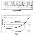
- Figures 2 and 3 show two different frequency against time curves for two frequency step methods of the present invention.
- Figure 4 illustrates an equivalent circuit and a voltage against position curve during low frequency driving of a prior art display.
- Figure 5 illustrates an equivalent circuit and a voltage against position curve similar to those of Figure 4 but showing the situation during high frequency driving of the same prior art display as in Figure 4 .
- Figure 6 illustrates an equivalent circuit and a voltage against position curve similar to those of Figure 5 but showing the situation during high frequency driving of a multi-point contact display.
- the present invention provides a frequency step method for driving dielectrophoretic displays (and a corresponding display using this method) and describes a multi-point contact display which does not fall within the scope of the invention.
- the frequency step method of the present invention is a method for operating a dielectrophoretic display which is a variation of the varying frequency drive method of the aforementioned U.S. Patent No. 7,116,466 .
- the display is driven using not only a low frequency which causes the particles to undergo electrophoretic motion and produce a first optical state, and a high frequency which causes the particles to undergo dielectrophoretic motion and produce a second optical state different from the first optical state, but also at least multiple intermediate frequencies.
- the increase in frequency needed to bring about a change from electrophoretic to dielectrophoretic movement of the particles, is effected in a series of steps rather than in only two steps as in the prior art method.
- the frequency step method can be practiced using only a few frequency steps, it is desirable that a large number of frequency steps be used, since (the present inventors have found) the smaller the individual frequency steps the less likely is flicker to be perceived by an observer.
- continuous frequency variation is typically not practicable with the types of drive circuits normally used to drive electro-optic displays.
- the frequency step method will normally be practiced using discrete frequencies applied in succession, but it is still desirable that the individual frequency steps be kept small, so that in effect the dielectrophoretic medium undergoes a gradual increase in drive frequency.
- the period for which each frequency is applied is also significant although the optimum period for application of each frequency will vary with the characteristics of the drive circuitry and the specific dielectrophoretic medium used. It is desired to give an observer an impression of a smooth continuous change in optical transmission rather than a series of discrete steps.
- the amplitude i.e., the voltage applied across the display
- use of a constant amplitude is typically preferred since it allows the use of simpler drive circuitry.
- the low frequency steps often perform well at lower voltages, use of lower voltages in the low frequency steps will reduce the overall power consumption of the display.
- Figure 1 of the accompanying drawings shows schematically a voltage against time curve for one prior art frequency step method.
- the display is driven, using a square wave alternating voltage, at frequency f 1 for a time t 1 , then at a higher frequency f 2 for a time t 2 , and thereafter at a still higher frequency f 3 for a time t 3 .
- Table below shows a more typical waveform of the present invention for driving a dielectrophoretic display from its closed to its open state.
- this preferred waveform steps from 100 Hz to 500 Hz in 16 separate steps of 25 Hz each, with a period of 0.2 seconds between each step. It has been found that such a gradual increase in drive frequency results in improved (increased) transmission in the open state of the display. Based upon microscopic observation, it is believed (although the invention is in no way limited by this belief) that this improved transmission is due to improved pigment packing at the wall of the capsule or droplet.
- Figures 2 and 3 illustrate frequency against time curves for two different frequency step methods of the present invention, both of which operate at constant voltage.
- the dielectrophoretic medium is assumed to have an optimal closed frequency of 30 Hz and an optimal open frequency of 1000 Hz, these being typical of those obtained in practice.
- the transition range is 60-500 Hz.
- 277 different frequencies are each applied for 0.05 seconds, with the frequency increasing exponentially with time. It will be seen that the display spends approximately 8 seconds out of the total 14 second of the opening transition within the transition range, and it has been found that this dwell time within the transition range is sufficient to provide a good open state.
- Figure 3 illustrate a frequency against time curve which may be easier to implement with simple circuitry than the exponential frequency curve of Figure 2 .
- the frequency is rapidly increased from the optimal closed frequency of 30 Hz to the 60 Hz lower end of the transition range in three steps, with each frequency being applied for 0.2 seconds. Within the transition region, the frequency is linearly increased in a number of very small frequency steps, conveniently 1 Hz, with each frequency being applied for a minimal period of 0.03 seconds. Once the frequency reaches the 500 Hz upper limit of the transition region, the frequency is then raised in 50 Hz steps, with each frequency being applied for 0.2 seconds.
- This frequency against time curve permits the display to spend more than 13 seconds of the 16 second total transition time within the transition range, and produces an open state which is very close to optimal.
- the frequency step method of the present invention can include any of the optional features of the drive methods described in the aforementioned U.S. Patent No. 7,116,466 and 2006/0038772 .
- the frequency step method may include periods of zero voltage and changes in the amplitude of the drive voltage.
- a display may be provided with insulating layers disposed between the electrodes and the dielectrophoretic medium. Such an insulating layer may have a volume resistivity of about 10 9 to about 10 11 ohm cm. In some cases, the insulating layer remote from the viewing surface may be formed by an adhesive layer.
- the fluid surrounding the particles may have dissolved or dispersed therein a polymer having an intrinsic viscosity of ⁇ in the suspending fluid and being substantially free from ionic or ionizable groups in the suspending fluid, the polymer being present in the suspending fluid in a concentration of from about 0.5 ⁇ -1 to about 2.0 ⁇ -1 .
- the polymer may be polyisobutylene.
- the display may comprise a color array adjacent the display so as to be visible to the observer, such that the color of the display perceived by the observer can be varied by changing the open and closed optical states of the various pixels of the display.
- the frequency step method of the present invention can produce a smooth and fast transition to a fully open, highly transmissive state, and may also be used to drive the display to mid-gray levels, i.e., to optical states intermediate the fully open and fully closed states.
- electrophoretic media typically have high volume resistivities of about 10 10 ohm cm, so that when a DC field is applied across the medium, the current draw is very low and results only from electrical leakage through the medium.
- the electrophoretic medium acts as a capacitor, which is charged and discharged in each alternating current half-cycle.
- the impedance of the electrophoretic medium is inversely proportional to the drive frequency, and the current flowing during high frequency operation is much larger than that flowing during DC driving.
- the materials normally used to form light-transmissive electrodes (which are typically single electrodes extending across the entire display) in electrophoretic and dielectrophoretic displays are of moderate conductivity; for example, indium tin oxide (ITO) has a conductivity of about 300 ohms/square. Accordingly, when a large display (for example, 11 by 14 inches or 279 by 355 mm) is being driven at high frequency, a substantial voltage drop can occur within the light-transmissive electrode between a point at which a conductor used to connect the light-transmissive electrode to a voltage source contacts the light-transmissive electrode, and a point on the light-transmissive electrode remote from this conductor. (The conductor, which does not need to be light transmissive and is typically a metal trace, will normally have a conductivity much greater than that of the light-transmissive electrode.)
- Figure 4 illustrates the situation during DC (or very low frequency AC) driving.
- the electrophoretic medium in effect acts as a series of capacitors (strictly speaking, as a series of capacitors in parallel with very high resistance resistors, but this makes essentially no difference for present purposes), and there is essentially no voltage drop within the light-transmissive layer.
- Figure 5 illustrates the situation during high frequency AC driving.
- the electrophoretic medium acts as a series of resistors in series with the inherent resistance of the light-transmissive electrode, and a substantial voltage drop takes place within the light-transmissive electrode, so that the voltage on the electrode varies depending upon the distance from the conductor.
- Variations in electrode voltage within the light-transmissive electrode are undesirable because they produce differing electric fields in different parts of the same display which are intended to be subject to the same electrical field, and thus causing different parts of the display to switch at different rates. For example, if a display were to be rewritten from (say) black text on a white background to solid black, variations in electrode voltage within the light-transmissive electrode could cause a visible "wave" whereby portions of the white background closest to the conductor would switch first and portions further from the conductor would switch later. Such a wave artifact is normally objectionable to the user of the display.
- the conductor is connected to the light-transmissive electrode at a plurality of spaced points.
- the conductor could be arranged to contact the light-transmissive electrode at the mid-point of each edge of the electrode. This may be especially useful in displays sufficiently large that at least one point on the display is 200 mm or more from a single conductor connection point. In practice, most variable transmission windows used in buildings will be at least this large.
- the conductor has the form of a conductive trace which extends around the entire periphery, or substantially the entire periphery, of the light-transmissive electrode.
- Such a conductive trace should have as high a conductivity as possible; for example, screen printed silver paint, with a conductivity of about 0.02 ohms/square, has been found to produce uniform switching on displays up to 11 by 14 inches (279 by 355 mm), whereas screen printed carbon paint, with a conductivity of about 15 ohms/square, has been unsatisfactory on such large displays.
- the present invention not only provides more uniform switching in large displays but also improves the reliability and durability of the displays due to reduced resistive heating within the light-transmissive electrode. It will be appreciated that variable transmission windows have two light-transmissive electrodes on opposed sides of the electrophoretic medium, and in such windows it will normally be desirable to apply the present invention to both light-transmissive electrodes, although we do not absolutely exclude the possibility that the invention might be applied to only one of two light-transmissive electrodes.
- the utility of the present invention is not, however, confined to variable transmission windows; the invention can be applied to displays having one light-transmissive electrode and one or more opaque electrodes, such as the displays used in electronic book readers and similar devices, to improve switching uniformity in such displays when it is necessary or desirable to use drive schemes which require high frequency driving.
Landscapes
- Physics & Mathematics (AREA)
- Nonlinear Science (AREA)
- General Physics & Mathematics (AREA)
- Engineering & Computer Science (AREA)
- Chemical & Material Sciences (AREA)
- Optics & Photonics (AREA)
- Theoretical Computer Science (AREA)
- Crystallography & Structural Chemistry (AREA)
- Mathematical Physics (AREA)
- Computer Hardware Design (AREA)
- Health & Medical Sciences (AREA)
- Life Sciences & Earth Sciences (AREA)
- Chemical Kinetics & Catalysis (AREA)
- Electrochemistry (AREA)
- Molecular Biology (AREA)
- Electrochromic Elements, Electrophoresis, Or Variable Reflection Or Absorption Elements (AREA)
- Control Of Indicators Other Than Cathode Ray Tubes (AREA)
Claims (8)
- Verfahren zum Betreiben einer dielektrophoretischen Anzeigevorrichtung, wobei das Verfahren folgende Schritte umfasst:Bereitstellen eines dielektrophoretischen Mediums, das ein Fluid und eine Vielzahl von mindestens einer Teilchenart innerhalb des Fluids umfasst;Anlegen an das Medium eines elektrischen Feldes, das eine erste Frequenz aufweist, wodurch die Teilchen dazu veranlasst werden, eine elektrophoretische Bewegung zu erfahren, und ein erster optischer Zustand erzeugt wird;Anlegen an das Medium mindestens eines elektrischen Feldes, das eine zweite Zwischenfrequenz aufweist, die höher als die erste Frequenz ist, wodurch die Teilchen dazu veranlasst werden, eine dielektrophoretische Bewegung zu erfahren; undAnlegen an das Medium eines elektrischen Feldes, das eine dritte Frequenz aufweist, die höher als die zweite Zwischenfrequenz ist, wodurch die Teilchen dazu veranlasst werden, eine dielektrophoretische Bewegung zu erfahren, und ein zweiter optischer Zustand erzeugt wird, der anders als der erste optische Zustand ist; wobei das Verfahren dadurch gekennzeichnet ist, dass mehrere elektrische Felder mit Zwischenfrequenzen zwischen den Feldern mit ersten und dritten Frequenzen verwendet werden, so dass innerhalb des Übergangsbereichs, der als von zweimal der optimalen Frequenz des geschlossenen Zustandes bis zur Hälfte der optimalen Frequenz des offenen Zustandes reichend definiert ist, wobei die optimale Frequenz des geschlossenen Zustandes die Frequenz ist, auf der eine minimale optische Übertragung ohne störendes Flimmern erzeugt wird, und die optimale Frequenz des offenen Zustandes die Mindestfrequenz ist, die eine optische Übertragung innerhalb von 1 Prozent der optischen Höchstübertragung erzeugt, die auf einer höheren Frequenz und der gleichen Steuerspannung erreicht werden kann, kein Frequenzschritt zwischen aufeinanderfolgenden angelegten elektrischen Feldern 10 Prozent des Gesamtfrequenzunterschiedes zwischen den ersten und dritten Frequenzen übersteigt.
- Verfahren nach Anspruch 1, wobei kein Frequenzschritt innerhalb des Übergangsbereichs zwischen aufeinanderfolgenden angelegten elektrischen Feldern 5 Prozent des Gesamtfrequenzunterschieds zwischen den ersten und dritten Frequenzen übersteigt.
- Verfahren nach Anspruch 2, wobei kein Frequenzschritt innerhalb des Übergangsbereichs zwischen aufeinanderfolgenden angelegten elektrischen Feldern 1 Prozent des Gesamtfrequenzunterschieds zwischen den ersten und dritten Frequenzen übersteigt.
- Verfahren nach Anspruch 1, wobei die Frequenzschritte innerhalb des Übergangsbereichs kleiner sind als die Frequenzschritte außerhalb des Übergangsbereichs.
- Verfahren nach Anspruch 1, wobei die elektrischen Felder der ersten, der Zwischen- und der dritten Frequenz alle mit im Wesentlichen der gleichen Amplitude angelegt werden.
- Verfahren nach Anspruch 1, wobei das elektrische Feld der dritten Frequenz mit einer größeren Amplitude als das elektrische Feld der ersten Frequenz angelegt wird.
- Dielektrophoretische Anzeigevorrichtung, umfassend;
ein dielektrophoretisches Medium, das ein Fluid und eine Vielzahl von mindestens einer Teilchenart innerhalb des Fluids umfasst;
mindestens eine Elektrode, die angeordnet ist, um ein elektrisches Feld an das dielektrophoretische Medium anzulegen; und
Feldsteuermittel zum Steuern des elektrischen Feldes, das von der mindestens einen Elektrode angelegt wird, wobei die Feldsteuermittel angeordnet sind, um ein elektrisches Feld anzulegen, das eine erste Frequenz aufweist, das die Teilchen dazu veranlasst, eine elektrophoretische Bewegung zu erfahren, und einen ersten optischen Zustand zu erzeugen; wobei mindestens ein elektrisches Feld eine zweite Zwischenfrequenz aufweist, die höher als die erste Frequenz ist, wodurch die Teilchen dazu veranlasst werden, eine dielektrophoretische Bewegung zu erfahren, und ein elektrisches Feld eine dritte Frequenz aufweist, die höher als die zweite Zwischenfrequenz ist, wodurch die Teilchen dazu veranlasst werden, eine dielektrophoretische Bewegung zu erfahren, und ein zweiter optischer Zustand erzeugt wird, der anders als der erste optische Zustand ist;
wobei die Anzeigevorrichtung dadurch gekennzeichnet ist, dass die Feldsteuermittel angeordnet sind, um mehrere elektrische Felder mit Zwischenfrequenz zwischen den Feldern mit der ersten und dritten Frequenz anzulegen, so dass innerhalb des Übergangsbereichs, der als von zweimal der optimalen Frequenz des geschlossenen Zustandes bis zur Hälfte der optimalen Frequenz des offenen Zustandes reichend definiert ist, wobei die optimale Frequenz des geschlossenen Zustandes die Frequenz ist, auf der eine minimale optische Übertragung ohne störendes Flimmern erzeugt wird, und die optimale Frequenz des offenen Zustandes die Mindestfrequenz ist, die eine optische Übertragung innerhalb von 1 Prozent der optischen Höchstübertragung erzeugt, die auf einer höheren Frequenz und der gleichen Steuerspannung erreicht werden kann, kein Frequenzschritt zwischen aufeinanderfolgenden angelegten elektrischen Feldern 10 Prozent des Gesamtfrequenzunterschiedes zwischen den ersten und dritten Frequenzen übersteigt. - Variables Übertragungsfenster, Lichtmodulator, elektronisches Buchlesegerät, tragbarer Computer, Tablet-Computer, Mobiltelefon, Smart-Card, Symbol, Uhr, Regaletikett oder Flash-Laufwerk, umfassend eine Anzeigevorrichtung nach Anspruch 7.
Priority Applications (1)
| Application Number | Priority Date | Filing Date | Title |
|---|---|---|---|
| EP12007387A EP2555182A1 (de) | 2007-02-02 | 2008-01-24 | Elektrophoretische Anzeige mit transparenter Elektrode und damit verbundenem Leite |
Applications Claiming Priority (3)
| Application Number | Priority Date | Filing Date | Title |
|---|---|---|---|
| US88787607P | 2007-02-02 | 2007-02-02 | |
| US11/949,316 US20080136774A1 (en) | 2004-07-27 | 2007-12-03 | Methods for driving electrophoretic displays using dielectrophoretic forces |
| PCT/US2008/051885 WO2008097721A1 (en) | 2007-02-02 | 2008-01-24 | Methods for driving electrophoretic displays using dielectrophoretic forces |
Related Child Applications (1)
| Application Number | Title | Priority Date | Filing Date |
|---|---|---|---|
| EP12007387.9 Division-Into | 2012-10-26 |
Publications (3)
| Publication Number | Publication Date |
|---|---|
| EP2126885A1 EP2126885A1 (de) | 2009-12-02 |
| EP2126885A4 EP2126885A4 (de) | 2011-04-13 |
| EP2126885B1 true EP2126885B1 (de) | 2013-01-02 |
Family
ID=39497400
Family Applications (2)
| Application Number | Title | Priority Date | Filing Date |
|---|---|---|---|
| EP08728187A Active EP2126885B1 (de) | 2007-02-02 | 2008-01-24 | Verfahren zum antrieb elektrophoretischer anzeigen über dielektrophoretische kräfte |
| EP12007387A Ceased EP2555182A1 (de) | 2007-02-02 | 2008-01-24 | Elektrophoretische Anzeige mit transparenter Elektrode und damit verbundenem Leite |
Family Applications After (1)
| Application Number | Title | Priority Date | Filing Date |
|---|---|---|---|
| EP12007387A Ceased EP2555182A1 (de) | 2007-02-02 | 2008-01-24 | Elektrophoretische Anzeige mit transparenter Elektrode und damit verbundenem Leite |
Country Status (5)
| Country | Link |
|---|---|
| US (1) | US20080136774A1 (de) |
| EP (2) | EP2126885B1 (de) |
| JP (3) | JP5632164B2 (de) |
| CN (1) | CN101601080B (de) |
| WO (1) | WO2008097721A1 (de) |
Families Citing this family (160)
| Publication number | Priority date | Publication date | Assignee | Title |
|---|---|---|---|---|
| US7583251B2 (en) | 1995-07-20 | 2009-09-01 | E Ink Corporation | Dielectrophoretic displays |
| US7848006B2 (en) | 1995-07-20 | 2010-12-07 | E Ink Corporation | Electrophoretic displays with controlled amounts of pigment |
| US7999787B2 (en) | 1995-07-20 | 2011-08-16 | E Ink Corporation | Methods for driving electrophoretic displays using dielectrophoretic forces |
| US8040594B2 (en) | 1997-08-28 | 2011-10-18 | E Ink Corporation | Multi-color electrophoretic displays |
| DE69920228T2 (de) | 1998-07-08 | 2005-01-27 | E-Ink Corp., Cambridge | Verfahren zur verbesserung der farbwiedergabe in elektrophoretischen vorrichtungen, welche mikrokapseln verwenden |
| US7030854B2 (en) | 2001-03-13 | 2006-04-18 | E Ink Corporation | Apparatus for displaying drawings |
| US7679814B2 (en) | 2001-04-02 | 2010-03-16 | E Ink Corporation | Materials for use in electrophoretic displays |
| US8390918B2 (en) | 2001-04-02 | 2013-03-05 | E Ink Corporation | Electrophoretic displays with controlled amounts of pigment |
| US9530363B2 (en) | 2001-11-20 | 2016-12-27 | E Ink Corporation | Methods and apparatus for driving electro-optic displays |
| US7223672B2 (en) | 2002-04-24 | 2007-05-29 | E Ink Corporation | Processes for forming backplanes for electro-optic displays |
| US7843621B2 (en) | 2002-06-10 | 2010-11-30 | E Ink Corporation | Components and testing methods for use in the production of electro-optic displays |
| US8363299B2 (en) | 2002-06-10 | 2013-01-29 | E Ink Corporation | Electro-optic displays, and processes for the production thereof |
| US7839564B2 (en) | 2002-09-03 | 2010-11-23 | E Ink Corporation | Components and methods for use in electro-optic displays |
| US20130063333A1 (en) | 2002-10-16 | 2013-03-14 | E Ink Corporation | Electrophoretic displays |
| US10726798B2 (en) | 2003-03-31 | 2020-07-28 | E Ink Corporation | Methods for operating electro-optic displays |
| US9230492B2 (en) | 2003-03-31 | 2016-01-05 | E Ink Corporation | Methods for driving electro-optic displays |
| US20110164301A1 (en) | 2003-11-05 | 2011-07-07 | E Ink Corporation | Electro-optic displays, and materials for use therein |
| US8177942B2 (en) | 2003-11-05 | 2012-05-15 | E Ink Corporation | Electro-optic displays, and materials for use therein |
| US11250794B2 (en) | 2004-07-27 | 2022-02-15 | E Ink Corporation | Methods for driving electrophoretic displays using dielectrophoretic forces |
| US7843624B2 (en) | 2006-03-08 | 2010-11-30 | E Ink Corporation | Electro-optic displays, and materials and methods for production thereof |
| US8390301B2 (en) | 2006-03-08 | 2013-03-05 | E Ink Corporation | Electro-optic displays, and materials and methods for production thereof |
| US7649666B2 (en) | 2006-12-07 | 2010-01-19 | E Ink Corporation | Components and methods for use in electro-optic displays |
| US7688497B2 (en) * | 2007-01-22 | 2010-03-30 | E Ink Corporation | Multi-layer sheet for use in electro-optic displays |
| CN101836167B (zh) | 2007-01-22 | 2013-11-06 | 伊英克公司 | 用在电光显示器中的多层板 |
| US7826129B2 (en) | 2007-03-06 | 2010-11-02 | E Ink Corporation | Materials for use in electrophoretic displays |
| US9199441B2 (en) | 2007-06-28 | 2015-12-01 | E Ink Corporation | Processes for the production of electro-optic displays, and color filters for use therein |
| US8034209B2 (en) | 2007-06-29 | 2011-10-11 | E Ink Corporation | Electro-optic displays, and materials and methods for production thereof |
| US20090122389A1 (en) | 2007-11-14 | 2009-05-14 | E Ink Corporation | Electro-optic assemblies, and adhesives and binders for use therein |
| WO2009117730A1 (en) | 2008-03-21 | 2009-09-24 | E Ink Corporation | Electro-optic displays and color filters |
| KR101214877B1 (ko) | 2008-04-11 | 2012-12-24 | 이 잉크 코포레이션 | 전기-광학 디스플레이들을 구동시키기 위한 방법 |
| WO2009129217A2 (en) | 2008-04-14 | 2009-10-22 | E Ink Corporation | Methods for driving electro-optic displays |
| TWI484273B (zh) | 2009-02-09 | 2015-05-11 | E Ink Corp | 電泳粒子 |
| US8098418B2 (en) | 2009-03-03 | 2012-01-17 | E. Ink Corporation | Electro-optic displays, and color filters for use therein |
| US9390661B2 (en) | 2009-09-15 | 2016-07-12 | E Ink California, Llc | Display controller system |
| US8654436B1 (en) | 2009-10-30 | 2014-02-18 | E Ink Corporation | Particles for use in electrophoretic displays |
| WO2011097228A2 (en) | 2010-02-02 | 2011-08-11 | E Ink Corporation | Method for driving electro-optic displays |
| EP2553522B1 (de) | 2010-04-02 | 2016-03-23 | E-Ink Corporation | Elektrophoretische medien |
| TWI484275B (zh) | 2010-05-21 | 2015-05-11 | E Ink Corp | 光電顯示器及其驅動方法、微型空腔電泳顯示器 |
| JP5660853B2 (ja) * | 2010-11-05 | 2015-01-28 | 三菱鉛筆株式会社 | 電気泳動表示媒体用シート及びこれを用いた電気泳動表示媒体 |
| CN106448574B (zh) | 2012-02-01 | 2019-07-12 | 伊英克公司 | 用于驱动电光显示器的方法 |
| US11030936B2 (en) | 2012-02-01 | 2021-06-08 | E Ink Corporation | Methods and apparatus for operating an electro-optic display in white mode |
| JP2015143725A (ja) * | 2012-05-17 | 2015-08-06 | シャープ株式会社 | 表示装置 |
| US9513743B2 (en) | 2012-06-01 | 2016-12-06 | E Ink Corporation | Methods for driving electro-optic displays |
| US10282033B2 (en) | 2012-06-01 | 2019-05-07 | E Ink Corporation | Methods for updating electro-optic displays when drawing or writing on the display |
| US10037735B2 (en) | 2012-11-16 | 2018-07-31 | E Ink Corporation | Active matrix display with dual driving modes |
| US9721495B2 (en) | 2013-02-27 | 2017-08-01 | E Ink Corporation | Methods for driving electro-optic displays |
| CN106782353B (zh) | 2013-03-01 | 2020-01-10 | 伊英克公司 | 用于驱动电光显示器的方法 |
| CN105378554B (zh) | 2013-05-14 | 2019-01-22 | 伊英克公司 | 彩色电泳显示器 |
| US9620048B2 (en) | 2013-07-30 | 2017-04-11 | E Ink Corporation | Methods for driving electro-optic displays |
| EP4156165A3 (de) | 2013-07-31 | 2023-06-21 | E Ink Corporation | Verfahren zur ansteuerung elektrooptischer anzeigen |
| TWI550332B (zh) | 2013-10-07 | 2016-09-21 | 電子墨水加利福尼亞有限責任公司 | 用於彩色顯示裝置的驅動方法 |
| US10380931B2 (en) | 2013-10-07 | 2019-08-13 | E Ink California, Llc | Driving methods for color display device |
| US10726760B2 (en) | 2013-10-07 | 2020-07-28 | E Ink California, Llc | Driving methods to produce a mixed color state for an electrophoretic display |
| US10657869B2 (en) | 2014-09-10 | 2020-05-19 | E Ink Corporation | Methods for driving color electrophoretic displays |
| EP3191892B1 (de) | 2014-09-10 | 2020-01-01 | E Ink Corporation | Gefärbte elektrophoretische anzeigen |
| JP6634080B2 (ja) | 2014-11-07 | 2020-01-22 | イー インク コーポレイション | 電気光学ディスプレイの用途 |
| US10197883B2 (en) | 2015-01-05 | 2019-02-05 | E Ink Corporation | Electro-optic displays, and methods for driving same |
| TWI699605B (zh) | 2015-01-05 | 2020-07-21 | 美商電子墨水股份有限公司 | 用於驅動顯示器之方法 |
| CN107111990B (zh) | 2015-01-30 | 2020-03-17 | 伊英克公司 | 用于电光显示器的字体控制以及相关设备和方法 |
| WO2016126963A1 (en) | 2015-02-04 | 2016-08-11 | E Ink Corporation | Electro-optic displays displaying in dark mode and light mode, and related apparatus and methods |
| EP3289561A4 (de) | 2015-04-27 | 2018-11-21 | E Ink Corporation | Verfahren und vorrichtungen zur ansteuerung von anzeigesystemen |
| US10997930B2 (en) | 2015-05-27 | 2021-05-04 | E Ink Corporation | Methods and circuitry for driving display devices |
| US10040954B2 (en) | 2015-05-28 | 2018-08-07 | E Ink California, Llc | Electrophoretic medium comprising a mixture of charge control agents |
| US11087644B2 (en) | 2015-08-19 | 2021-08-10 | E Ink Corporation | Displays intended for use in architectural applications |
| US10388233B2 (en) | 2015-08-31 | 2019-08-20 | E Ink Corporation | Devices and techniques for electronically erasing a drawing device |
| US11657774B2 (en) | 2015-09-16 | 2023-05-23 | E Ink Corporation | Apparatus and methods for driving displays |
| WO2017049020A1 (en) | 2015-09-16 | 2017-03-23 | E Ink Corporation | Apparatus and methods for driving displays |
| US10803813B2 (en) | 2015-09-16 | 2020-10-13 | E Ink Corporation | Apparatus and methods for driving displays |
| WO2017059179A1 (en) | 2015-10-01 | 2017-04-06 | E Ink Corporation | Variable color and transmission coverings |
| EP3359622B1 (de) | 2015-10-06 | 2021-01-13 | E Ink Corporation | Verbesserte elektrophoretische medien für niedrige temperaturen |
| WO2017066152A1 (en) | 2015-10-12 | 2017-04-20 | E Ink California, Llc | Electrophoretic display device |
| CN108350279B (zh) | 2015-11-11 | 2020-03-17 | 伊英克公司 | 官能化的喹吖啶酮颜料 |
| TWI631542B (zh) | 2015-11-18 | 2018-08-01 | 美商電子墨水股份有限公司 | 電光顯示器 |
| TWI658312B (zh) | 2016-02-08 | 2019-05-01 | 美商電子墨水股份有限公司 | 用於在白模式中操作電光顯示器的方法及設備 |
| US10572707B2 (en) * | 2016-02-09 | 2020-02-25 | Synaptics Incorporated | Transparent fingerprint sensor pattern |
| EP3427254A4 (de) | 2016-03-09 | 2020-02-26 | E Ink Corporation | Verfahren zur ansteuerung elektro-optischer anzeigen |
| US10593272B2 (en) | 2016-03-09 | 2020-03-17 | E Ink Corporation | Drivers providing DC-balanced refresh sequences for color electrophoretic displays |
| EP3465628B1 (de) | 2016-05-24 | 2020-07-08 | E Ink Corporation | Verfahren zur darstellung von farbbildern |
| CN109154758A (zh) | 2016-05-31 | 2019-01-04 | 伊英克公司 | 用于电光显示器的背板 |
| CN110383370B (zh) | 2017-03-03 | 2022-07-12 | 伊英克公司 | 电光显示器及驱动方法 |
| CA3200340A1 (en) | 2017-03-06 | 2018-09-13 | E Ink Corporation | Method and apparatus for rendering color images |
| US10444592B2 (en) | 2017-03-09 | 2019-10-15 | E Ink Corporation | Methods and systems for transforming RGB image data to a reduced color set for electro-optic displays |
| RU2742928C1 (ru) | 2017-04-04 | 2021-02-11 | Е Инк Корпорэйшн | Способы управления электрооптическими дисплеями |
| US11404013B2 (en) | 2017-05-30 | 2022-08-02 | E Ink Corporation | Electro-optic displays with resistors for discharging remnant charges |
| CN110709766B (zh) | 2017-05-30 | 2023-03-10 | 伊英克公司 | 电光显示器 |
| JP7079845B2 (ja) | 2017-09-12 | 2022-06-02 | イー インク コーポレイション | 電気光学ディスプレイを駆動する方法 |
| US11721295B2 (en) | 2017-09-12 | 2023-08-08 | E Ink Corporation | Electro-optic displays, and methods for driving same |
| KR102417289B1 (ko) | 2017-10-18 | 2022-07-06 | 뉴클라 뉴클레익스 리미티드 | 박막 트랜지스터들 및 용량성 센싱을 갖는 듀얼 기판들을 포함하는 디지털 미세유체 디바이스들 |
| KR102184385B1 (ko) | 2017-11-03 | 2020-11-30 | 주식회사 엘지화학 | 투과도 가변 장치 |
| CN116243504A (zh) | 2017-12-19 | 2023-06-09 | 伊英克公司 | 电光显示器的应用 |
| EP3729191B1 (de) | 2017-12-22 | 2023-06-07 | E Ink Corporation | Elektrooptische anzeigen und verfahren zur ansteuerung davon |
| WO2019144097A1 (en) | 2018-01-22 | 2019-07-25 | E Ink Corporation | Electro-optic displays, and methods for driving same |
| CN112313572B (zh) * | 2018-06-28 | 2024-08-16 | 伊英克公司 | 用于可变透射电泳介质的驱动方法 |
| EP3824346A4 (de) | 2018-07-17 | 2022-04-13 | E Ink California, LLC | Elektro-optische anzeigen und ansteuerungsverfahren |
| CN112470067B (zh) | 2018-08-10 | 2025-04-18 | 伊英克公司 | 具有反射器的可切换的光准直层 |
| CN112470066A (zh) | 2018-08-10 | 2021-03-09 | 伊英克加利福尼亚有限责任公司 | 用于包括双稳态电泳流体的可切换的光准直层的驱动波形 |
| US11397366B2 (en) | 2018-08-10 | 2022-07-26 | E Ink California, Llc | Switchable light-collimating layer including bistable electrophoretic fluid |
| US11353759B2 (en) | 2018-09-17 | 2022-06-07 | Nuclera Nucleics Ltd. | Backplanes with hexagonal and triangular electrodes |
| KR102577837B1 (ko) | 2018-10-15 | 2023-09-12 | 이 잉크 코포레이션 | 디지털 미세유체 전달 디바이스 |
| CN113016024B (zh) | 2018-11-30 | 2023-09-05 | 伊英克加利福尼亚有限责任公司 | 电光显示器和驱动方法 |
| WO2020122917A1 (en) * | 2018-12-13 | 2020-06-18 | E Ink Corporation | Illumination systems for reflective displays |
| EP3966628B1 (de) * | 2019-05-07 | 2025-04-23 | E Ink Corporation | Ansteuerverfahren für eine variable lichtübertragungsvorrichtung |
| US11460722B2 (en) | 2019-05-10 | 2022-10-04 | E Ink Corporation | Colored electrophoretic displays |
| CN114641820B (zh) | 2019-11-14 | 2024-01-05 | 伊英克公司 | 用于驱动电光显示器的方法 |
| US11257445B2 (en) | 2019-11-18 | 2022-02-22 | E Ink Corporation | Methods for driving electro-optic displays |
| KR102720289B1 (ko) | 2020-05-31 | 2024-10-21 | 이 잉크 코포레이션 | 전기 광학 디스플레이들, 및 이를 구동하기 위한 방법들 |
| US11520202B2 (en) | 2020-06-11 | 2022-12-06 | E Ink Corporation | Electro-optic displays, and methods for driving same |
| KR102725786B1 (ko) | 2020-08-04 | 2024-11-05 | 삼성전자주식회사 | 디스플레이를 포함하는 전자 장치 및 그의 동작 방법 |
| US12027129B2 (en) | 2020-08-31 | 2024-07-02 | E Ink Corporation | Electro-optic displays and driving methods |
| CA3189174A1 (en) | 2020-09-15 | 2022-03-24 | Stephen J. Telfer | Improved driving voltages for advanced color electrophoretic displays and displays with improved driving voltages |
| US11846863B2 (en) | 2020-09-15 | 2023-12-19 | E Ink Corporation | Coordinated top electrode—drive electrode voltages for switching optical state of electrophoretic displays using positive and negative voltages of different magnitudes |
| US12181767B2 (en) | 2020-09-15 | 2024-12-31 | E Ink Corporation | Five-particle electrophoretic medium with improved black optical state |
| JP7542140B2 (ja) | 2020-09-15 | 2024-08-29 | イー インク コーポレイション | 高速かつ高コントラストな光学状態切替を提供する4粒子電気泳動媒体 |
| KR102742380B1 (ko) | 2020-10-01 | 2024-12-12 | 이 잉크 코포레이션 | 전기 광학 디스플레이, 및 그것을 구동하는 방법 |
| JP2023544208A (ja) | 2020-11-02 | 2023-10-20 | イー インク コーポレイション | カラー画像をレンダリングするための方法および装置 |
| EP4237909A4 (de) | 2020-11-02 | 2024-05-22 | E Ink Corporation | Steuerungssequenzen zur entfernung von vorherigen zustandsinformationen aus elektrophoretischen farbanzeigen |
| CN116490913A (zh) | 2020-11-02 | 2023-07-25 | 伊英克公司 | 用于在多色电泳显示器中实现原色集的增强型推挽(epp)波形 |
| WO2022125500A1 (en) | 2020-12-08 | 2022-06-16 | E Ink Corporation | Methods for driving electro-optic displays |
| EP4292075A4 (de) | 2021-02-09 | 2025-01-15 | E Ink Corporation | Kontinuierliche wellenformansteuerung in elektrophoretischen mehrfarbenanzeigen |
| JP7688154B2 (ja) | 2021-04-16 | 2025-06-03 | イー インク コーポレイション | 薄型縁シールを伴う電気泳動ディスプレイ |
| KR102815301B1 (ko) | 2021-07-29 | 2025-05-29 | 이 잉크 코포레이션 | 잔류 전압들을 방전시키기 위한 오믹 전도성 저장 커패시터들을 갖는 전기-광학 디스플레이들 |
| EP4388370A4 (de) | 2021-08-18 | 2025-07-02 | E Ink Corp | Verfahren zur ansteuerung elektrooptischer anzeigen |
| WO2023043714A1 (en) | 2021-09-14 | 2023-03-23 | E Ink Corporation | Coordinated top electrode - drive electrode voltages for switching optical state of electrophoretic displays using positive and negative voltages of different magnitudes |
| CN117957490A (zh) | 2021-09-16 | 2024-04-30 | 伊英克公司 | 具有改进透射率的可切换光准直层 |
| US11830448B2 (en) | 2021-11-04 | 2023-11-28 | E Ink Corporation | Methods for driving electro-optic displays |
| TWI830484B (zh) | 2021-11-05 | 2024-01-21 | 美商電子墨水股份有限公司 | 一種用於驅動在陣列中具有複數個顯示像素的彩色電泳顯示器之方法及執行此方法之電泳顯示器 |
| US12339559B1 (en) | 2021-12-09 | 2025-06-24 | E Ink Corporation | Electro-optic displays and methods for discharging remnant voltage using backlight |
| EP4453649A1 (de) | 2021-12-22 | 2024-10-30 | E Ink Corporation | Hochspannungsansteuerung unter verwendung von top-plane-umschaltung mit nullspannungsrahmen zwischen ansteuerungsrahmen |
| WO2023122142A1 (en) | 2021-12-22 | 2023-06-29 | E Ink Corporation | Methods for driving electro-optic displays |
| CN119920209B (zh) | 2021-12-27 | 2025-08-26 | 伊英克公司 | 用于驱动电光显示器的方法 |
| EP4457797A1 (de) | 2021-12-30 | 2024-11-06 | E Ink Corporation | Verfahren zur ansteuerung elektrooptischer anzeigen |
| EP4460725A1 (de) | 2022-01-04 | 2024-11-13 | E Ink Corporation | Elektrophoretische medien mit elektrophoretischen partikeln und einer kombination von ladungssteuermitteln |
| WO2023164099A1 (en) | 2022-02-28 | 2023-08-31 | E Ink Corporation | Parking space management system |
| EP4515522A1 (de) | 2022-04-27 | 2025-03-05 | E Ink Corporation | Farbanzeigen mit konfiguration zur umwandlung von rgb-bilddaten zur anzeige auf erweitertem elektronischem farbpapier |
| JP2025528088A (ja) | 2022-08-25 | 2025-08-26 | イー インク コーポレイション | 電気泳動ディスプレイのための大域的色モードと直接更新モードとの間で切り替えるときのインパルス平衡のための遷移駆動モード |
| US12548529B2 (en) | 2022-10-25 | 2026-02-10 | E Ink Corporation | Methods for driving electro-optic displays |
| US12190836B2 (en) | 2023-01-27 | 2025-01-07 | E Ink Corporation | Multi-element pixel electrode circuits for electro-optic displays and methods for driving the same |
| EP4673938A1 (de) | 2023-02-28 | 2026-01-07 | E Ink Corporation | Ansteuerungsschema für verbesserte farbskala in elektrophoretischen farbanzeigen |
| US12451049B2 (en) | 2023-03-24 | 2025-10-21 | E Ink Corporation | Methods for driving electro-optic displays |
| US20240402562A1 (en) | 2023-06-05 | 2024-12-05 | E Ink Corporation | Color electrophoretic medium having four pigment particle system addressable by waveforms having four voltage levels |
| WO2025006476A1 (en) | 2023-06-27 | 2025-01-02 | E Ink Corporation | Multi-particle electrophoretic display having low-flash image updates |
| WO2025006130A1 (en) | 2023-06-27 | 2025-01-02 | E Ink Corporation | Electrophoretic device with ambient light sensor and adaptive whiteness restoring and color balancing frontlight |
| AU2024307676A1 (en) | 2023-06-27 | 2025-09-04 | E Ink Corporation | Time-shifted waveforms for multi-particle electrophoretic displays providing low-flash image updates |
| US20250053058A1 (en) | 2023-08-08 | 2025-02-13 | E Ink Corporation | Backplanes for segmented electro-optic displays and methods of manufacturing same |
| US12456436B2 (en) | 2023-10-05 | 2025-10-28 | E Ink Corporation | Staged gate voltage control |
| US20250138382A1 (en) | 2023-10-31 | 2025-05-01 | E Ink Corporation | Reflective display and projected capacitive touch sensor with shared transparent electrode |
| US20250191547A1 (en) | 2023-12-06 | 2025-06-12 | E Ink Corporation | Method of driving a color electophoretic display to form images without dithering |
| WO2025128843A1 (en) | 2023-12-15 | 2025-06-19 | E Ink Corporation | Fast response color waveforms for multiparticle electrophoretic displays |
| WO2025136446A1 (en) | 2023-12-22 | 2025-06-26 | E Ink Corporation | Five-particle electrophoretic medium with improved black optical state |
| US20250216737A1 (en) | 2024-01-02 | 2025-07-03 | E Ink Corporation | Electrophoretic media comprising a cationic charge control agent |
| WO2025147504A1 (en) | 2024-01-05 | 2025-07-10 | E Ink Corporation | An electrophoretic medium comprising particles having a pigment core and a polymeric shell |
| US20250237922A1 (en) | 2024-01-19 | 2025-07-24 | E Ink Corporation | Flexible segmented electro-optic displays and methods of manufacture |
| US20250239231A1 (en) | 2024-01-20 | 2025-07-24 | E Ink Corporation | Methods for delivering low-ghosting partial updates in color electrophoretic displays |
| US20250239232A1 (en) | 2024-01-24 | 2025-07-24 | E Ink Corporation | Methods for producing full-color epaper images with low grain |
| WO2025230802A1 (en) | 2024-04-30 | 2025-11-06 | E Ink Corporation | A variable light transmission device comprising microcells |
| US20250370306A1 (en) | 2024-05-30 | 2025-12-04 | E Ink Corporation | Chemically-Resistant Multi-Layered Electro-Optic Device and a Method of Making the Same |
| WO2026006119A1 (en) | 2024-06-26 | 2026-01-02 | E Ink Corporation | A variable light transmission device comprising microcells |
| WO2026006117A1 (en) | 2024-06-26 | 2026-01-02 | E Ink Corporation | A variable light transmission device comprising microcells |
| WO2026006234A1 (en) | 2024-06-26 | 2026-01-02 | E Ink Corporation | A variable light transmission device comprising microcells |
| WO2026055042A1 (en) | 2024-09-03 | 2026-03-12 | E Ink Corporation | Methods for removing color shifts after electrophoretic display updates |
Family Cites Families (186)
| Publication number | Priority date | Publication date | Assignee | Title |
|---|---|---|---|---|
| US3385927A (en) * | 1964-08-26 | 1968-05-28 | Stromberg Carlson Corp | Display device utilizing a medium that alters the degree of refraction of light |
| JPS5788173U (de) * | 1980-11-19 | 1982-05-31 | ||
| US4418346A (en) | 1981-05-20 | 1983-11-29 | Batchelder J Samuel | Method and apparatus for providing a dielectrophoretic display of visual information |
| JPH0518737Y2 (de) * | 1985-06-19 | 1993-05-18 | ||
| JPS638636A (ja) * | 1986-06-28 | 1988-01-14 | Nippon Denso Co Ltd | 液晶防眩型反射鏡 |
| FR2664058B1 (fr) | 1990-06-27 | 1996-09-20 | Fondis Sa | Detecteur de matieres volatiles imbrulees, notamment pour appareil de chauffage. |
| US5745094A (en) | 1994-12-28 | 1998-04-28 | International Business Machines Corporation | Electrophoretic display |
| US6639578B1 (en) | 1995-07-20 | 2003-10-28 | E Ink Corporation | Flexible displays |
| US7259744B2 (en) | 1995-07-20 | 2007-08-21 | E Ink Corporation | Dielectrophoretic displays |
| US6124851A (en) | 1995-07-20 | 2000-09-26 | E Ink Corporation | Electronic book with multiple page displays |
| US6727881B1 (en) | 1995-07-20 | 2004-04-27 | E Ink Corporation | Encapsulated electrophoretic displays and methods and materials for making the same |
| US6017584A (en) | 1995-07-20 | 2000-01-25 | E Ink Corporation | Multi-color electrophoretic displays and materials for making the same |
| US7411719B2 (en) | 1995-07-20 | 2008-08-12 | E Ink Corporation | Electrophoretic medium and process for the production thereof |
| US6515649B1 (en) | 1995-07-20 | 2003-02-04 | E Ink Corporation | Suspended particle displays and materials for making the same |
| US7167155B1 (en) | 1995-07-20 | 2007-01-23 | E Ink Corporation | Color electrophoretic displays |
| US6262706B1 (en) | 1995-07-20 | 2001-07-17 | E Ink Corporation | Retroreflective electrophoretic displays and materials for making the same |
| US7106296B1 (en) | 1995-07-20 | 2006-09-12 | E Ink Corporation | Electronic book with multiple page displays |
| US7109968B2 (en) | 1995-07-20 | 2006-09-19 | E Ink Corporation | Non-spherical cavity electrophoretic displays and methods and materials for making the same |
| US6118426A (en) | 1995-07-20 | 2000-09-12 | E Ink Corporation | Transducers and indicators having printed displays |
| US6710540B1 (en) | 1995-07-20 | 2004-03-23 | E Ink Corporation | Electrostatically-addressable electrophoretic display |
| US7079305B2 (en) | 2001-03-19 | 2006-07-18 | E Ink Corporation | Electrophoretic medium and process for the production thereof |
| US6459418B1 (en) | 1995-07-20 | 2002-10-01 | E Ink Corporation | Displays combining active and non-active inks |
| US6866760B2 (en) | 1998-08-27 | 2005-03-15 | E Ink Corporation | Electrophoretic medium and process for the production thereof |
| US6120588A (en) | 1996-07-19 | 2000-09-19 | E Ink Corporation | Electronically addressable microencapsulated ink and display thereof |
| US7071913B2 (en) | 1995-07-20 | 2006-07-04 | E Ink Corporation | Retroreflective electrophoretic displays and materials for making the same |
| US7327511B2 (en) * | 2004-03-23 | 2008-02-05 | E Ink Corporation | Light modulators |
| US7999787B2 (en) * | 1995-07-20 | 2011-08-16 | E Ink Corporation | Methods for driving electrophoretic displays using dielectrophoretic forces |
| US7193625B2 (en) | 1999-04-30 | 2007-03-20 | E Ink Corporation | Methods for driving electro-optic displays, and apparatus for use therein |
| US6664944B1 (en) | 1995-07-20 | 2003-12-16 | E-Ink Corporation | Rear electrode structures for electrophoretic displays |
| US6120839A (en) | 1995-07-20 | 2000-09-19 | E Ink Corporation | Electro-osmotic displays and materials for making the same |
| US8139050B2 (en) | 1995-07-20 | 2012-03-20 | E Ink Corporation | Addressing schemes for electronic displays |
| US6641708B1 (en) * | 1996-01-31 | 2003-11-04 | Board Of Regents, The University Of Texas System | Method and apparatus for fractionation using conventional dielectrophoresis and field flow fractionation |
| US6538801B2 (en) | 1996-07-19 | 2003-03-25 | E Ink Corporation | Electrophoretic displays using nanoparticles |
| US6721083B2 (en) | 1996-07-19 | 2004-04-13 | E Ink Corporation | Electrophoretic displays using nanoparticles |
| EP1231500B1 (de) | 1996-07-19 | 2007-03-07 | E-Ink Corporation | Elektronisch adressierbare mikroverkapselte Tinte |
| US6323989B1 (en) | 1996-07-19 | 2001-11-27 | E Ink Corporation | Electrophoretic displays using nanoparticles |
| US5930026A (en) | 1996-10-25 | 1999-07-27 | Massachusetts Institute Of Technology | Nonemissive displays and piezoelectric power supplies therefor |
| US5961804A (en) | 1997-03-18 | 1999-10-05 | Massachusetts Institute Of Technology | Microencapsulated electrophoretic display |
| US6980196B1 (en) | 1997-03-18 | 2005-12-27 | Massachusetts Institute Of Technology | Printable electronic display |
| US6839158B2 (en) | 1997-08-28 | 2005-01-04 | E Ink Corporation | Encapsulated electrophoretic displays having a monolayer of capsules and materials and methods for making the same |
| US6252564B1 (en) | 1997-08-28 | 2001-06-26 | E Ink Corporation | Tiled displays |
| US6177921B1 (en) | 1997-08-28 | 2001-01-23 | E Ink Corporation | Printable electrode structures for displays |
| US6232950B1 (en) | 1997-08-28 | 2001-05-15 | E Ink Corporation | Rear electrode structures for displays |
| US6300932B1 (en) | 1997-08-28 | 2001-10-09 | E Ink Corporation | Electrophoretic displays with luminescent particles and materials for making the same |
| WO1999010768A1 (en) * | 1997-08-28 | 1999-03-04 | E-Ink Corporation | Novel addressing schemes for electrophoretic displays |
| US6825829B1 (en) | 1997-08-28 | 2004-11-30 | E Ink Corporation | Adhesive backed displays |
| US7247379B2 (en) | 1997-08-28 | 2007-07-24 | E Ink Corporation | Electrophoretic particles, and processes for the production thereof |
| US7002728B2 (en) | 1997-08-28 | 2006-02-21 | E Ink Corporation | Electrophoretic particles, and processes for the production thereof |
| US6067185A (en) | 1997-08-28 | 2000-05-23 | E Ink Corporation | Process for creating an encapsulated electrophoretic display |
| CA2273981C (en) | 1997-12-10 | 2003-07-08 | Mitsubishi Denki Kabushiki Kaisha | Mobile communication system |
| WO1999047970A1 (en) | 1998-03-18 | 1999-09-23 | E-Ink Corporation | Electrophoretic displays and systems for addressing such displays |
| US6753999B2 (en) | 1998-03-18 | 2004-06-22 | E Ink Corporation | Electrophoretic displays in portable devices and systems for addressing such displays |
| US6704133B2 (en) | 1998-03-18 | 2004-03-09 | E-Ink Corporation | Electro-optic display overlays and systems for addressing such displays |
| US7075502B1 (en) | 1998-04-10 | 2006-07-11 | E Ink Corporation | Full color reflective display with multichromatic sub-pixels |
| US6518949B2 (en) | 1998-04-10 | 2003-02-11 | E Ink Corporation | Electronic displays using organic-based field effect transistors |
| AU3767899A (en) | 1998-04-27 | 1999-11-16 | E-Ink Corporation | Shutter mode microencapsulated electrophoretic display |
| CA2330950A1 (en) | 1998-05-12 | 1999-11-18 | E Ink Corporation | Microencapsulated electrophoretic electrostatically-addressed media for drawing device applications |
| CA2333358A1 (en) | 1998-06-22 | 1999-12-29 | E Ink Corporation | Means of addressing microencapsulated display media |
| ATE228681T1 (de) | 1998-07-08 | 2002-12-15 | E Ink Corp | Verfahren und vorrichtung zum messen des zustandes einer elektrophoretischen anzeigevorrichtung |
| DE69920228T2 (de) | 1998-07-08 | 2005-01-27 | E-Ink Corp., Cambridge | Verfahren zur verbesserung der farbwiedergabe in elektrophoretischen vorrichtungen, welche mikrokapseln verwenden |
| US20030102858A1 (en) | 1998-07-08 | 2003-06-05 | E Ink Corporation | Method and apparatus for determining properties of an electrophoretic display |
| CA2336744A1 (en) | 1998-07-22 | 2000-02-03 | Jonathan D. Albert | Electronic display |
| US7256766B2 (en) | 1998-08-27 | 2007-08-14 | E Ink Corporation | Electrophoretic display comprising optical biasing element |
| US6271823B1 (en) | 1998-09-16 | 2001-08-07 | International Business Machines Corporation | Reflective electrophoretic display with laterally adjacent color cells using a reflective panel |
| US6225971B1 (en) | 1998-09-16 | 2001-05-01 | International Business Machines Corporation | Reflective electrophoretic display with laterally adjacent color cells using an absorbing panel |
| US6144361A (en) | 1998-09-16 | 2000-11-07 | International Business Machines Corporation | Transmissive electrophoretic display with vertical electrodes |
| US6184856B1 (en) | 1998-09-16 | 2001-02-06 | International Business Machines Corporation | Transmissive electrophoretic display with laterally adjacent color cells |
| US6376828B1 (en) | 1998-10-07 | 2002-04-23 | E Ink Corporation | Illumination system for nonemissive electronic displays |
| US6262833B1 (en) | 1998-10-07 | 2001-07-17 | E Ink Corporation | Capsules for electrophoretic displays and methods for making the same |
| CA2347866A1 (en) | 1998-11-02 | 2000-05-11 | Russell J. Wilcox | Broadcast system for display devices made of electronic ink |
| US6312304B1 (en) | 1998-12-15 | 2001-11-06 | E Ink Corporation | Assembly of microencapsulated electronic displays |
| US6506438B2 (en) | 1998-12-15 | 2003-01-14 | E Ink Corporation | Method for printing of transistor arrays on plastic substrates |
| EP1141889A1 (de) | 1998-12-18 | 2001-10-10 | E Ink Corporation | Anzeigemedium mit elektronischer tinte zur sicherung und authentifizierung |
| US6724519B1 (en) | 1998-12-21 | 2004-04-20 | E-Ink Corporation | Protective electrodes for electrophoretic displays |
| AU2591400A (en) | 1998-12-22 | 2000-07-12 | E-Ink Corporation | Method of manufacturing of a discrete electronic device |
| AU4205400A (en) | 1999-04-06 | 2000-10-23 | E-Ink Corporation | Microcell electrophoretic displays |
| CA2365847A1 (en) | 1999-04-06 | 2000-10-12 | Gregg M. Duthaler | Methods for producing droplets for use in capsule-based electrophoretic displays |
| US6498114B1 (en) | 1999-04-09 | 2002-12-24 | E Ink Corporation | Method for forming a patterned semiconductor film |
| US6842657B1 (en) | 1999-04-09 | 2005-01-11 | E Ink Corporation | Reactive formation of dielectric layers and protection of organic layers in organic semiconductor device fabrication |
| US6504524B1 (en) | 2000-03-08 | 2003-01-07 | E Ink Corporation | Addressing methods for displays having zero time-average field |
| US7119772B2 (en) | 1999-04-30 | 2006-10-10 | E Ink Corporation | Methods for driving bistable electro-optic displays, and apparatus for use therein |
| US6531997B1 (en) | 1999-04-30 | 2003-03-11 | E Ink Corporation | Methods for addressing electrophoretic displays |
| US7012600B2 (en) | 1999-04-30 | 2006-03-14 | E Ink Corporation | Methods for driving bistable electro-optic displays, and apparatus for use therein |
| US8115729B2 (en) | 1999-05-03 | 2012-02-14 | E Ink Corporation | Electrophoretic display element with filler particles |
| AU4816300A (en) | 1999-05-03 | 2000-11-17 | E-Ink Corporation | Display unit for electronic shelf price label system |
| US7038655B2 (en) | 1999-05-03 | 2006-05-02 | E Ink Corporation | Electrophoretic ink composed of particles with field dependent mobilities |
| US7119759B2 (en) | 1999-05-03 | 2006-10-10 | E Ink Corporation | Machine-readable displays |
| US8009348B2 (en) | 1999-05-03 | 2011-08-30 | E Ink Corporation | Machine-readable displays |
| US7030412B1 (en) | 1999-05-05 | 2006-04-18 | E Ink Corporation | Minimally-patterned semiconductor devices for display applications |
| JP5394601B2 (ja) | 1999-07-01 | 2014-01-22 | イー インク コーポレイション | スペーサが提供された電気泳動媒体 |
| AU6365900A (en) | 1999-07-21 | 2001-02-13 | E-Ink Corporation | Use of a storage capacitor to enhance the performance of an active matrix drivenelectronic display |
| WO2001008242A1 (en) | 1999-07-21 | 2001-02-01 | E Ink Corporation | Preferred methods for producing electrical circuit elements used to control an electronic display |
| AU7094400A (en) | 1999-08-31 | 2001-03-26 | E-Ink Corporation | A solvent annealing process for forming a thin semiconductor film with advantageous properties |
| US6545291B1 (en) | 1999-08-31 | 2003-04-08 | E Ink Corporation | Transistor design for use in the construction of an electronically driven display |
| JP4114288B2 (ja) | 1999-10-18 | 2008-07-09 | コニカミノルタビジネステクノロジーズ株式会社 | 画像データ出力装置および画像データの出力方法 |
| US6672921B1 (en) | 2000-03-03 | 2004-01-06 | Sipix Imaging, Inc. | Manufacturing process for electrophoretic display |
| US6788449B2 (en) | 2000-03-03 | 2004-09-07 | Sipix Imaging, Inc. | Electrophoretic display and novel process for its manufacture |
| US7893435B2 (en) | 2000-04-18 | 2011-02-22 | E Ink Corporation | Flexible electronic circuits and displays including a backplane comprising a patterned metal foil having a plurality of apertures extending therethrough |
| JP2003531487A (ja) | 2000-04-18 | 2003-10-21 | イー−インク コーポレイション | 薄膜トランジスタを製造するためのプロセス |
| AU2001259451A1 (en) * | 2000-05-04 | 2001-11-12 | Schott Donnelly Llc | Chromogenic glazing |
| US6683333B2 (en) | 2000-07-14 | 2004-01-27 | E Ink Corporation | Fabrication of electronic circuit elements using unpatterned semiconductor layers |
| US6816147B2 (en) | 2000-08-17 | 2004-11-09 | E Ink Corporation | Bistable electro-optic display, and method for addressing same |
| WO2002045061A2 (en) | 2000-11-29 | 2002-06-06 | E Ink Corporation | Addressing circuitry for large electronic displays |
| AU2002230610A1 (en) | 2000-12-05 | 2002-06-18 | E-Ink Corporation | Portable eclectronic apparatus with additional electro-optical display |
| US7030854B2 (en) | 2001-03-13 | 2006-04-18 | E Ink Corporation | Apparatus for displaying drawings |
| US7679814B2 (en) | 2001-04-02 | 2010-03-16 | E Ink Corporation | Materials for use in electrophoretic displays |
| US20050156340A1 (en) | 2004-01-20 | 2005-07-21 | E Ink Corporation | Preparation of capsules |
| US7230750B2 (en) | 2001-05-15 | 2007-06-12 | E Ink Corporation | Electrophoretic media and processes for the production thereof |
| DE60210949T2 (de) | 2001-04-02 | 2006-09-21 | E-Ink Corp., Cambridge | Elektrophoresemedium mit verbesserter Bildstabilität |
| US6580545B2 (en) | 2001-04-19 | 2003-06-17 | E Ink Corporation | Electrochromic-nanoparticle displays |
| JP4188091B2 (ja) | 2001-05-15 | 2008-11-26 | イー インク コーポレイション | 電気泳動粒子 |
| WO2002093245A1 (en) | 2001-05-15 | 2002-11-21 | E Ink Corporation | Electrophoretic displays containing magnetic particles |
| JP4061863B2 (ja) * | 2001-06-20 | 2008-03-19 | 富士ゼロックス株式会社 | 画像表示装置及び表示駆動方法 |
| EP1415193B1 (de) | 2001-07-09 | 2012-03-14 | E Ink Corporation | Elektro-optische anzeigeeinrichtung mit laminierklebstoffschicht |
| US6982178B2 (en) | 2002-06-10 | 2006-01-03 | E Ink Corporation | Components and methods for use in electro-optic displays |
| JP2004535599A (ja) | 2001-07-09 | 2004-11-25 | イー−インク コーポレイション | 電気光学ディスプレイおよび接着組成物 |
| US7535624B2 (en) | 2001-07-09 | 2009-05-19 | E Ink Corporation | Electro-optic display and materials for use therein |
| US7110163B2 (en) | 2001-07-09 | 2006-09-19 | E Ink Corporation | Electro-optic display and lamination adhesive for use therein |
| US6967640B2 (en) | 2001-07-27 | 2005-11-22 | E Ink Corporation | Microencapsulated electrophoretic display with integrated driver |
| US6819471B2 (en) | 2001-08-16 | 2004-11-16 | E Ink Corporation | Light modulation by frustration of total internal reflection |
| US6825970B2 (en) | 2001-09-14 | 2004-11-30 | E Ink Corporation | Methods for addressing electro-optic materials |
| KR100914574B1 (ko) | 2001-09-19 | 2009-08-31 | 가부시키가이샤 브리지스톤 | 화상 표시용 입자 및 화상 표시 장치 |
| GB0124247D0 (en) * | 2001-10-10 | 2001-11-28 | Koninkl Philips Electronics Nv | Colour display device |
| US7202847B2 (en) | 2002-06-28 | 2007-04-10 | E Ink Corporation | Voltage modulated driver circuits for electro-optic displays |
| US7952557B2 (en) | 2001-11-20 | 2011-05-31 | E Ink Corporation | Methods and apparatus for driving electro-optic displays |
| US7528822B2 (en) | 2001-11-20 | 2009-05-05 | E Ink Corporation | Methods for driving electro-optic displays |
| US8558783B2 (en) | 2001-11-20 | 2013-10-15 | E Ink Corporation | Electro-optic displays with reduced remnant voltage |
| CN102789764B (zh) * | 2001-11-20 | 2015-05-27 | 伊英克公司 | 驱动双稳态电光显示器的方法 |
| EP2363745A1 (de) | 2001-12-10 | 2011-09-07 | Bridgestone Corporation | Bildanzeige |
| AU2002357842A1 (en) | 2001-12-13 | 2003-06-23 | E Ink Corporation | Electrophoretic electronic displays with films having a low index of refraction |
| US6900851B2 (en) | 2002-02-08 | 2005-05-31 | E Ink Corporation | Electro-optic displays and optical systems for addressing such displays |
| AU2003207186A1 (en) | 2002-02-15 | 2003-09-04 | Bridgestone Corporation | Image display unit |
| DE60320640T2 (de) | 2002-03-06 | 2009-06-10 | Bridgestone Corp. | Bildanzeigevorrichtung und verfahren |
| US6950220B2 (en) | 2002-03-18 | 2005-09-27 | E Ink Corporation | Electro-optic displays, and methods for driving same |
| AU2003235217A1 (en) | 2002-04-17 | 2003-10-27 | Bridgestone Corporation | Image display unit |
| WO2003092077A2 (en) | 2002-04-24 | 2003-11-06 | E Ink Corporation | Electronic displays |
| US7223672B2 (en) | 2002-04-24 | 2007-05-29 | E Ink Corporation | Processes for forming backplanes for electro-optic displays |
| US7190008B2 (en) | 2002-04-24 | 2007-03-13 | E Ink Corporation | Electro-optic displays, and components for use therein |
| EP1500971B1 (de) | 2002-04-26 | 2010-01-13 | Bridgestone Corporation | Methode zur Herstellung eines sphärischen Partikels zur Bildanzeige |
| US6958848B2 (en) | 2002-05-23 | 2005-10-25 | E Ink Corporation | Capsules, materials for use therein and electrophoretic media and displays containing such capsules |
| US7110164B2 (en) | 2002-06-10 | 2006-09-19 | E Ink Corporation | Electro-optic displays, and processes for the production thereof |
| US7554712B2 (en) | 2005-06-23 | 2009-06-30 | E Ink Corporation | Edge seals for, and processes for assembly of, electro-optic displays |
| CN100437714C (zh) * | 2002-06-13 | 2008-11-26 | 伊英克公司 | 用于驱动电光显示器的方法 |
| EP1536271A4 (de) | 2002-06-21 | 2008-02-13 | Bridgestone Corp | Bildanzeige und verfahren zur herstellung einer bildanzeige |
| US6842279B2 (en) | 2002-06-27 | 2005-01-11 | E Ink Corporation | Illumination system for nonemissive electronic displays |
| AU2003252656A1 (en) | 2002-07-17 | 2004-02-02 | Bridgestone Corporation | Image display |
| FR2842916B1 (fr) * | 2002-07-25 | 2004-12-03 | Genewave | Vitrage optiquement actif |
| WO2004017135A2 (en) | 2002-08-06 | 2004-02-26 | E Ink Corporation | Protection of electro-optic displays against thermal effects |
| US7312916B2 (en) | 2002-08-07 | 2007-12-25 | E Ink Corporation | Electrophoretic media containing specularly reflective particles |
| WO2004023202A1 (en) | 2002-09-03 | 2004-03-18 | E Ink Corporation | Electrophoretic medium with gaseous suspending fluid |
| CN101109885B (zh) | 2002-09-03 | 2012-06-13 | 伊英克公司 | 电光显示器 |
| US7839564B2 (en) | 2002-09-03 | 2010-11-23 | E Ink Corporation | Components and methods for use in electro-optic displays |
| CN101118362A (zh) | 2002-12-16 | 2008-02-06 | 伊英克公司 | 电光显示器的底板 |
| WO2004055586A1 (ja) | 2002-12-17 | 2004-07-01 | Bridgestone Corporation | 画像表示パネルの製造方法,画像表示装置の製造方法,及び,画像表示装置 |
| US6922276B2 (en) | 2002-12-23 | 2005-07-26 | E Ink Corporation | Flexible electro-optic displays |
| AU2003289452A1 (en) | 2002-12-24 | 2004-07-22 | Bridgestone Corporation | Image display |
| US6987603B2 (en) | 2003-01-31 | 2006-01-17 | E Ink Corporation | Construction of electrophoretic displays |
| EP1598694A4 (de) | 2003-02-25 | 2008-10-15 | Bridgestone Corp | Bildanzeigetafel und bildanzeigeeinheit |
| JPWO2004079442A1 (ja) | 2003-03-06 | 2006-06-08 | 株式会社ブリヂストン | 画像表示装置の製造方法及び画像表示装置 |
| US7339715B2 (en) | 2003-03-25 | 2008-03-04 | E Ink Corporation | Processes for the production of electrophoretic displays |
| US7012735B2 (en) | 2003-03-27 | 2006-03-14 | E Ink Corporaiton | Electro-optic assemblies, and materials for use therein |
| JP4579823B2 (ja) | 2003-04-02 | 2010-11-10 | 株式会社ブリヂストン | 画像表示媒体に用いる粒子、それを用いた画像表示用パネル及び画像表示装置 |
| WO2004099862A2 (en) | 2003-05-02 | 2004-11-18 | E Ink Corporation | Electrophoretic displays |
| US20050122563A1 (en) | 2003-07-24 | 2005-06-09 | E Ink Corporation | Electro-optic displays |
| JP4076222B2 (ja) * | 2003-07-25 | 2008-04-16 | 株式会社東芝 | 電気泳動表示装置 |
| EP2698784B1 (de) | 2003-08-19 | 2017-11-01 | E Ink Corporation | Elektrooptischer Bildschirm |
| JP5506137B2 (ja) | 2003-09-19 | 2014-05-28 | イー インク コーポレイション | 電子光学式ディスプレイにおけるエッジ効果を低減する方法 |
| CN101930118B (zh) | 2003-10-08 | 2013-05-29 | 伊英克公司 | 电润湿显示器 |
| US20050122306A1 (en) | 2003-10-29 | 2005-06-09 | E Ink Corporation | Electro-optic displays with single edge addressing and removable driver circuitry |
| EP1680774B9 (de) | 2003-11-05 | 2018-05-16 | E Ink Corporation | Elektrophoretisches medium für elektro-optische bildschirme |
| US8928562B2 (en) | 2003-11-25 | 2015-01-06 | E Ink Corporation | Electro-optic displays, and methods for driving same |
| US7206119B2 (en) | 2003-12-31 | 2007-04-17 | E Ink Corporation | Electro-optic displays, and method for driving same |
| US7075703B2 (en) | 2004-01-16 | 2006-07-11 | E Ink Corporation | Process for sealing electro-optic displays |
| US7388572B2 (en) | 2004-02-27 | 2008-06-17 | E Ink Corporation | Backplanes for electro-optic displays |
| US7492339B2 (en) | 2004-03-26 | 2009-02-17 | E Ink Corporation | Methods for driving bistable electro-optic displays |
| US20050253777A1 (en) | 2004-05-12 | 2005-11-17 | E Ink Corporation | Tiled displays and methods for driving same |
| US7236790B2 (en) | 2004-06-03 | 2007-06-26 | Intel Corporation | Distributed radar detection for WLAN |
| KR100601696B1 (ko) | 2004-07-27 | 2006-07-14 | 삼성전자주식회사 | 다이렉트 이미지 처리 방법 및 장치 |
| EP1779174A4 (de) | 2004-07-27 | 2010-05-05 | E Ink Corp | Elektrooptische anzeigen |
| US7453445B2 (en) | 2004-08-13 | 2008-11-18 | E Ink Corproation | Methods for driving electro-optic displays |
| JP2006154664A (ja) * | 2004-12-01 | 2006-06-15 | Bridgestone Corp | 情報表示用パネル及び情報表示装置 |
| JP4902956B2 (ja) * | 2004-12-03 | 2012-03-21 | 株式会社ブリヂストン | 情報表示用パネル及び情報表示装置 |
| US7230751B2 (en) | 2005-01-26 | 2007-06-12 | E Ink Corporation | Electrophoretic displays using gaseous fluids |
| JP4718859B2 (ja) | 2005-02-17 | 2011-07-06 | セイコーエプソン株式会社 | 電気泳動装置とその駆動方法、及び電子機器 |
| JP4690079B2 (ja) | 2005-03-04 | 2011-06-01 | セイコーエプソン株式会社 | 電気泳動装置とその駆動方法、及び電子機器 |
| US20070091417A1 (en) | 2005-10-25 | 2007-04-26 | E Ink Corporation | Electrophoretic media and displays with improved binder |
-
2007
- 2007-12-03 US US11/949,316 patent/US20080136774A1/en not_active Abandoned
-
2008
- 2008-01-24 EP EP08728187A patent/EP2126885B1/de active Active
- 2008-01-24 CN CN2008800039521A patent/CN101601080B/zh active Active
- 2008-01-24 WO PCT/US2008/051885 patent/WO2008097721A1/en not_active Ceased
- 2008-01-24 EP EP12007387A patent/EP2555182A1/de not_active Ceased
- 2008-01-24 JP JP2009548364A patent/JP5632164B2/ja active Active
-
2012
- 2012-09-04 JP JP2012194141A patent/JP2012238032A/ja not_active Withdrawn
-
2014
- 2014-07-07 JP JP2014139375A patent/JP2014186357A/ja active Pending
Also Published As
| Publication number | Publication date |
|---|---|
| EP2126885A4 (de) | 2011-04-13 |
| CN101601080B (zh) | 2013-10-23 |
| JP5632164B2 (ja) | 2014-11-26 |
| EP2555182A1 (de) | 2013-02-06 |
| JP2014186357A (ja) | 2014-10-02 |
| CN101601080A (zh) | 2009-12-09 |
| JP2012238032A (ja) | 2012-12-06 |
| US20080136774A1 (en) | 2008-06-12 |
| WO2008097721A1 (en) | 2008-08-14 |
| JP2010517115A (ja) | 2010-05-20 |
| HK1136901A1 (en) | 2010-07-09 |
| CN103474034A (zh) | 2013-12-25 |
| EP2126885A1 (de) | 2009-12-02 |
Similar Documents
| Publication | Publication Date | Title |
|---|---|---|
| EP2126885B1 (de) | Verfahren zum antrieb elektrophoretischer anzeigen über dielektrophoretische kräfte | |
| EP1735652B1 (de) | Verfahren zur herstellung eines elektrophoretischen mediums | |
| US7492497B2 (en) | Multi-layer light modulator | |
| US20080130092A1 (en) | Light modulators | |
| US20170168370A1 (en) | Methods for driving electrophoretic displays using dielectrophoretic forces | |
| JP7190515B2 (ja) | 可変透過電気泳動媒質の駆動方法 | |
| US11250794B2 (en) | Methods for driving electrophoretic displays using dielectrophoretic forces | |
| HK1188643B (en) | Methods for driving electrophoretic displays using dielectrophoretic forces | |
| HK1188643A (en) | Methods for driving electrophoretic displays using dielectrophoretic forces | |
| HK1136901B (en) | Methods for driving electrophoretic displays using dielectrophoretic forces | |
| HK40036104A (en) | Driving methods for variable transmission electro-phoretic media | |
| HK40036104B (zh) | 用於可变透射电泳介质的驱动方法 |
Legal Events
| Date | Code | Title | Description |
|---|---|---|---|
| PUAI | Public reference made under article 153(3) epc to a published international application that has entered the european phase |
Free format text: ORIGINAL CODE: 0009012 |
|
| 17P | Request for examination filed |
Effective date: 20090713 |
|
| AK | Designated contracting states |
Kind code of ref document: A1 Designated state(s): AT BE BG CH CY CZ DE DK EE ES FI FR GB GR HR HU IE IS IT LI LT LU LV MC MT NL NO PL PT RO SE SI SK TR |
|
| DAX | Request for extension of the european patent (deleted) | ||
| A4 | Supplementary search report drawn up and despatched |
Effective date: 20110316 |
|
| GRAP | Despatch of communication of intention to grant a patent |
Free format text: ORIGINAL CODE: EPIDOSNIGR1 |
|
| RIC1 | Information provided on ipc code assigned before grant |
Ipc: G09G 3/34 20060101AFI20120521BHEP Ipc: G02F 1/167 20060101ALI20120521BHEP |
|
| GRAS | Grant fee paid |
Free format text: ORIGINAL CODE: EPIDOSNIGR3 |
|
| GRAA | (expected) grant |
Free format text: ORIGINAL CODE: 0009210 |
|
| AK | Designated contracting states |
Kind code of ref document: B1 Designated state(s): AT BE BG CH CY CZ DE DK EE ES FI FR GB GR HR HU IE IS IT LI LT LU LV MC MT NL NO PL PT RO SE SI SK TR |
|
| REG | Reference to a national code |
Ref country code: GB Ref legal event code: FG4D |
|
| REG | Reference to a national code |
Ref country code: CH Ref legal event code: EP Ref country code: AT Ref legal event code: REF Ref document number: 591987 Country of ref document: AT Kind code of ref document: T Effective date: 20130115 |
|
| REG | Reference to a national code |
Ref country code: IE Ref legal event code: FG4D |
|
| REG | Reference to a national code |
Ref country code: DE Ref legal event code: R096 Ref document number: 602008021350 Country of ref document: DE Effective date: 20130228 |
|
| REG | Reference to a national code |
Ref country code: AT Ref legal event code: MK05 Ref document number: 591987 Country of ref document: AT Kind code of ref document: T Effective date: 20130102 |
|
| REG | Reference to a national code |
Ref country code: NL Ref legal event code: VDEP Effective date: 20130102 |
|
| PG25 | Lapsed in a contracting state [announced via postgrant information from national office to epo] |
Ref country code: SI Free format text: LAPSE BECAUSE OF FAILURE TO SUBMIT A TRANSLATION OF THE DESCRIPTION OR TO PAY THE FEE WITHIN THE PRESCRIBED TIME-LIMIT Effective date: 20130102 |
|
| REG | Reference to a national code |
Ref country code: LT Ref legal event code: MG4D |
|
| PG25 | Lapsed in a contracting state [announced via postgrant information from national office to epo] |
Ref country code: IS Free format text: LAPSE BECAUSE OF FAILURE TO SUBMIT A TRANSLATION OF THE DESCRIPTION OR TO PAY THE FEE WITHIN THE PRESCRIBED TIME-LIMIT Effective date: 20130502 Ref country code: NO Free format text: LAPSE BECAUSE OF FAILURE TO SUBMIT A TRANSLATION OF THE DESCRIPTION OR TO PAY THE FEE WITHIN THE PRESCRIBED TIME-LIMIT Effective date: 20130402 Ref country code: CZ Free format text: LAPSE BECAUSE OF FAILURE TO SUBMIT A TRANSLATION OF THE DESCRIPTION OR TO PAY THE FEE WITHIN THE PRESCRIBED TIME-LIMIT Effective date: 20130102 Ref country code: ES Free format text: LAPSE BECAUSE OF FAILURE TO SUBMIT A TRANSLATION OF THE DESCRIPTION OR TO PAY THE FEE WITHIN THE PRESCRIBED TIME-LIMIT Effective date: 20130413 Ref country code: LT Free format text: LAPSE BECAUSE OF FAILURE TO SUBMIT A TRANSLATION OF THE DESCRIPTION OR TO PAY THE FEE WITHIN THE PRESCRIBED TIME-LIMIT Effective date: 20130102 Ref country code: AT Free format text: LAPSE BECAUSE OF FAILURE TO SUBMIT A TRANSLATION OF THE DESCRIPTION OR TO PAY THE FEE WITHIN THE PRESCRIBED TIME-LIMIT Effective date: 20130102 Ref country code: BG Free format text: LAPSE BECAUSE OF FAILURE TO SUBMIT A TRANSLATION OF THE DESCRIPTION OR TO PAY THE FEE WITHIN THE PRESCRIBED TIME-LIMIT Effective date: 20130402 Ref country code: BE Free format text: LAPSE BECAUSE OF FAILURE TO SUBMIT A TRANSLATION OF THE DESCRIPTION OR TO PAY THE FEE WITHIN THE PRESCRIBED TIME-LIMIT Effective date: 20130102 Ref country code: SE Free format text: LAPSE BECAUSE OF FAILURE TO SUBMIT A TRANSLATION OF THE DESCRIPTION OR TO PAY THE FEE WITHIN THE PRESCRIBED TIME-LIMIT Effective date: 20130102 |
|
| PGFP | Annual fee paid to national office [announced via postgrant information from national office to epo] |
Ref country code: DE Payment date: 20130402 Year of fee payment: 6 |
|
| PG25 | Lapsed in a contracting state [announced via postgrant information from national office to epo] |
Ref country code: MC Free format text: LAPSE BECAUSE OF NON-PAYMENT OF DUE FEES Effective date: 20130131 Ref country code: LV Free format text: LAPSE BECAUSE OF FAILURE TO SUBMIT A TRANSLATION OF THE DESCRIPTION OR TO PAY THE FEE WITHIN THE PRESCRIBED TIME-LIMIT Effective date: 20130102 Ref country code: PL Free format text: LAPSE BECAUSE OF FAILURE TO SUBMIT A TRANSLATION OF THE DESCRIPTION OR TO PAY THE FEE WITHIN THE PRESCRIBED TIME-LIMIT Effective date: 20130102 Ref country code: NL Free format text: LAPSE BECAUSE OF FAILURE TO SUBMIT A TRANSLATION OF THE DESCRIPTION OR TO PAY THE FEE WITHIN THE PRESCRIBED TIME-LIMIT Effective date: 20130102 Ref country code: GR Free format text: LAPSE BECAUSE OF FAILURE TO SUBMIT A TRANSLATION OF THE DESCRIPTION OR TO PAY THE FEE WITHIN THE PRESCRIBED TIME-LIMIT Effective date: 20130403 Ref country code: PT Free format text: LAPSE BECAUSE OF FAILURE TO SUBMIT A TRANSLATION OF THE DESCRIPTION OR TO PAY THE FEE WITHIN THE PRESCRIBED TIME-LIMIT Effective date: 20130502 Ref country code: FI Free format text: LAPSE BECAUSE OF FAILURE TO SUBMIT A TRANSLATION OF THE DESCRIPTION OR TO PAY THE FEE WITHIN THE PRESCRIBED TIME-LIMIT Effective date: 20130102 |
|
| REG | Reference to a national code |
Ref country code: CH Ref legal event code: PL |
|
| PG25 | Lapsed in a contracting state [announced via postgrant information from national office to epo] |
Ref country code: HR Free format text: LAPSE BECAUSE OF FAILURE TO SUBMIT A TRANSLATION OF THE DESCRIPTION OR TO PAY THE FEE WITHIN THE PRESCRIBED TIME-LIMIT Effective date: 20130102 |
|
| REG | Reference to a national code |
Ref country code: IE Ref legal event code: MM4A |
|
| PG25 | Lapsed in a contracting state [announced via postgrant information from national office to epo] |
Ref country code: EE Free format text: LAPSE BECAUSE OF FAILURE TO SUBMIT A TRANSLATION OF THE DESCRIPTION OR TO PAY THE FEE WITHIN THE PRESCRIBED TIME-LIMIT Effective date: 20130102 Ref country code: RO Free format text: LAPSE BECAUSE OF FAILURE TO SUBMIT A TRANSLATION OF THE DESCRIPTION OR TO PAY THE FEE WITHIN THE PRESCRIBED TIME-LIMIT Effective date: 20130102 Ref country code: SK Free format text: LAPSE BECAUSE OF FAILURE TO SUBMIT A TRANSLATION OF THE DESCRIPTION OR TO PAY THE FEE WITHIN THE PRESCRIBED TIME-LIMIT Effective date: 20130102 Ref country code: CH Free format text: LAPSE BECAUSE OF NON-PAYMENT OF DUE FEES Effective date: 20130131 Ref country code: LI Free format text: LAPSE BECAUSE OF NON-PAYMENT OF DUE FEES Effective date: 20130131 Ref country code: DK Free format text: LAPSE BECAUSE OF FAILURE TO SUBMIT A TRANSLATION OF THE DESCRIPTION OR TO PAY THE FEE WITHIN THE PRESCRIBED TIME-LIMIT Effective date: 20130102 |
|
| PLBE | No opposition filed within time limit |
Free format text: ORIGINAL CODE: 0009261 |
|
| STAA | Information on the status of an ep patent application or granted ep patent |
Free format text: STATUS: NO OPPOSITION FILED WITHIN TIME LIMIT |
|
| PG25 | Lapsed in a contracting state [announced via postgrant information from national office to epo] |
Ref country code: CY Free format text: LAPSE BECAUSE OF FAILURE TO SUBMIT A TRANSLATION OF THE DESCRIPTION OR TO PAY THE FEE WITHIN THE PRESCRIBED TIME-LIMIT Effective date: 20130102 |
|
| 26N | No opposition filed |
Effective date: 20131003 |
|
| PG25 | Lapsed in a contracting state [announced via postgrant information from national office to epo] |
Ref country code: IT Free format text: LAPSE BECAUSE OF FAILURE TO SUBMIT A TRANSLATION OF THE DESCRIPTION OR TO PAY THE FEE WITHIN THE PRESCRIBED TIME-LIMIT Effective date: 20130102 |
|
| REG | Reference to a national code |
Ref country code: DE Ref legal event code: R097 Ref document number: 602008021350 Country of ref document: DE Effective date: 20131003 |
|
| PG25 | Lapsed in a contracting state [announced via postgrant information from national office to epo] |
Ref country code: IE Free format text: LAPSE BECAUSE OF NON-PAYMENT OF DUE FEES Effective date: 20130124 |
|
| PG25 | Lapsed in a contracting state [announced via postgrant information from national office to epo] |
Ref country code: MT Free format text: LAPSE BECAUSE OF FAILURE TO SUBMIT A TRANSLATION OF THE DESCRIPTION OR TO PAY THE FEE WITHIN THE PRESCRIBED TIME-LIMIT Effective date: 20130102 |
|
| REG | Reference to a national code |
Ref country code: DE Ref legal event code: R119 Ref document number: 602008021350 Country of ref document: DE |
|
| REG | Reference to a national code |
Ref country code: DE Ref legal event code: R119 Ref document number: 602008021350 Country of ref document: DE Effective date: 20140801 |
|
| PG25 | Lapsed in a contracting state [announced via postgrant information from national office to epo] |
Ref country code: DE Free format text: LAPSE BECAUSE OF NON-PAYMENT OF DUE FEES Effective date: 20140801 |
|
| PG25 | Lapsed in a contracting state [announced via postgrant information from national office to epo] |
Ref country code: TR Free format text: LAPSE BECAUSE OF FAILURE TO SUBMIT A TRANSLATION OF THE DESCRIPTION OR TO PAY THE FEE WITHIN THE PRESCRIBED TIME-LIMIT Effective date: 20130102 |
|
| PG25 | Lapsed in a contracting state [announced via postgrant information from national office to epo] |
Ref country code: HU Free format text: LAPSE BECAUSE OF FAILURE TO SUBMIT A TRANSLATION OF THE DESCRIPTION OR TO PAY THE FEE WITHIN THE PRESCRIBED TIME-LIMIT; INVALID AB INITIO Effective date: 20080124 Ref country code: LU Free format text: LAPSE BECAUSE OF NON-PAYMENT OF DUE FEES Effective date: 20130124 |
|
| REG | Reference to a national code |
Ref country code: FR Ref legal event code: PLFP Year of fee payment: 9 |
|
| REG | Reference to a national code |
Ref country code: FR Ref legal event code: PLFP Year of fee payment: 10 |
|
| REG | Reference to a national code |
Ref country code: FR Ref legal event code: PLFP Year of fee payment: 11 |
|
| PGFP | Annual fee paid to national office [announced via postgrant information from national office to epo] |
Ref country code: GB Payment date: 20251220 Year of fee payment: 19 |
|
| PGFP | Annual fee paid to national office [announced via postgrant information from national office to epo] |
Ref country code: FR Payment date: 20251217 Year of fee payment: 19 |