EP2125179B1 - Agitateur horizontal et procédé pour produire un courant dans un bassin de décantation avec l'agitateur horizontal - Google Patents
Agitateur horizontal et procédé pour produire un courant dans un bassin de décantation avec l'agitateur horizontal Download PDFInfo
- Publication number
- EP2125179B1 EP2125179B1 EP20080715766 EP08715766A EP2125179B1 EP 2125179 B1 EP2125179 B1 EP 2125179B1 EP 20080715766 EP20080715766 EP 20080715766 EP 08715766 A EP08715766 A EP 08715766A EP 2125179 B1 EP2125179 B1 EP 2125179B1
- Authority
- EP
- European Patent Office
- Prior art keywords
- horizontal agitator
- propeller
- submersible motor
- flow
- horizontal
- Prior art date
- Legal status (The legal status is an assumption and is not a legal conclusion. Google has not performed a legal analysis and makes no representation as to the accuracy of the status listed.)
- Active
Links
- 238000004519 manufacturing process Methods 0.000 title claims description 5
- 239000000835 fiber Substances 0.000 claims description 12
- 230000005489 elastic deformation Effects 0.000 claims description 10
- 239000002131 composite material Substances 0.000 claims description 9
- 239000000463 material Substances 0.000 claims description 4
- 239000002351 wastewater Substances 0.000 claims description 4
- OKTJSMMVPCPJKN-UHFFFAOYSA-N Carbon Chemical compound [C] OKTJSMMVPCPJKN-UHFFFAOYSA-N 0.000 claims description 3
- 239000004698 Polyethylene Substances 0.000 claims description 3
- 239000004760 aramid Substances 0.000 claims description 3
- 229920003235 aromatic polyamide Polymers 0.000 claims description 3
- 229910052799 carbon Inorganic materials 0.000 claims description 3
- 239000011159 matrix material Substances 0.000 claims description 3
- 239000004033 plastic Substances 0.000 claims description 3
- 229920003023 plastic Polymers 0.000 claims description 3
- -1 polyethylene Polymers 0.000 claims description 3
- 229920000573 polyethylene Polymers 0.000 claims description 3
- 229920002430 Fibre-reinforced plastic Polymers 0.000 claims description 2
- 239000011151 fibre-reinforced plastic Substances 0.000 claims description 2
- 239000002184 metal Substances 0.000 claims description 2
- 239000012530 fluid Substances 0.000 description 5
- 239000007788 liquid Substances 0.000 description 5
- 238000005452 bending Methods 0.000 description 4
- 238000000034 method Methods 0.000 description 4
- 230000005540 biological transmission Effects 0.000 description 2
- 230000015572 biosynthetic process Effects 0.000 description 2
- 239000012535 impurity Substances 0.000 description 2
- 230000006978 adaptation Effects 0.000 description 1
- 238000009954 braiding Methods 0.000 description 1
- 239000000356 contaminant Substances 0.000 description 1
- 239000003822 epoxy resin Substances 0.000 description 1
- 239000003733 fiber-reinforced composite Substances 0.000 description 1
- LNEPOXFFQSENCJ-UHFFFAOYSA-N haloperidol Chemical compound C1CC(O)(C=2C=CC(Cl)=CC=2)CCN1CCCC(=O)C1=CC=C(F)C=C1 LNEPOXFFQSENCJ-UHFFFAOYSA-N 0.000 description 1
- 239000013528 metallic particle Substances 0.000 description 1
- 229920000647 polyepoxide Polymers 0.000 description 1
- 229920005989 resin Polymers 0.000 description 1
- 239000011347 resin Substances 0.000 description 1
- XLYOFNOQVPJJNP-UHFFFAOYSA-N water Substances O XLYOFNOQVPJJNP-UHFFFAOYSA-N 0.000 description 1
Images


Classifications
-
- C—CHEMISTRY; METALLURGY
- C02—TREATMENT OF WATER, WASTE WATER, SEWAGE, OR SLUDGE
- C02F—TREATMENT OF WATER, WASTE WATER, SEWAGE, OR SLUDGE
- C02F3/00—Biological treatment of water, waste water, or sewage
- C02F3/02—Aerobic processes
- C02F3/12—Activated sludge processes
- C02F3/1278—Provisions for mixing or aeration of the mixed liquor
- C02F3/1284—Mixing devices
-
- B—PERFORMING OPERATIONS; TRANSPORTING
- B01—PHYSICAL OR CHEMICAL PROCESSES OR APPARATUS IN GENERAL
- B01F—MIXING, e.g. DISSOLVING, EMULSIFYING OR DISPERSING
- B01F27/00—Mixers with rotary stirring devices in fixed receptacles; Kneaders
- B01F27/05—Stirrers
- B01F27/051—Stirrers characterised by their elements, materials or mechanical properties
- B01F27/054—Deformable stirrers, e.g. deformed by a centrifugal force applied during operation
-
- B—PERFORMING OPERATIONS; TRANSPORTING
- B01—PHYSICAL OR CHEMICAL PROCESSES OR APPARATUS IN GENERAL
- B01F—MIXING, e.g. DISSOLVING, EMULSIFYING OR DISPERSING
- B01F27/00—Mixers with rotary stirring devices in fixed receptacles; Kneaders
- B01F27/25—Mixers with both stirrer and drive unit submerged in the material being mixed
-
- B—PERFORMING OPERATIONS; TRANSPORTING
- B01—PHYSICAL OR CHEMICAL PROCESSES OR APPARATUS IN GENERAL
- B01F—MIXING, e.g. DISSOLVING, EMULSIFYING OR DISPERSING
- B01F27/00—Mixers with rotary stirring devices in fixed receptacles; Kneaders
- B01F27/60—Mixers with rotary stirring devices in fixed receptacles; Kneaders with stirrers rotating about a horizontal or inclined axis
- B01F27/71—Mixers with rotary stirring devices in fixed receptacles; Kneaders with stirrers rotating about a horizontal or inclined axis with propellers
- B01F27/711—Mixers with rotary stirring devices in fixed receptacles; Kneaders with stirrers rotating about a horizontal or inclined axis with propellers co-operating with stationary guiding means, e.g. baffles
-
- B—PERFORMING OPERATIONS; TRANSPORTING
- B01—PHYSICAL OR CHEMICAL PROCESSES OR APPARATUS IN GENERAL
- B01F—MIXING, e.g. DISSOLVING, EMULSIFYING OR DISPERSING
- B01F35/00—Accessories for mixers; Auxiliary operations or auxiliary devices; Parts or details of general application
- B01F35/55—Baffles; Flow breakers
-
- B—PERFORMING OPERATIONS; TRANSPORTING
- B01—PHYSICAL OR CHEMICAL PROCESSES OR APPARATUS IN GENERAL
- B01F—MIXING, e.g. DISSOLVING, EMULSIFYING OR DISPERSING
- B01F2101/00—Mixing characterised by the nature of the mixed materials or by the application field
- B01F2101/305—Treatment of water, waste water or sewage
-
- Y—GENERAL TAGGING OF NEW TECHNOLOGICAL DEVELOPMENTS; GENERAL TAGGING OF CROSS-SECTIONAL TECHNOLOGIES SPANNING OVER SEVERAL SECTIONS OF THE IPC; TECHNICAL SUBJECTS COVERED BY FORMER USPC CROSS-REFERENCE ART COLLECTIONS [XRACs] AND DIGESTS
- Y02—TECHNOLOGIES OR APPLICATIONS FOR MITIGATION OR ADAPTATION AGAINST CLIMATE CHANGE
- Y02W—CLIMATE CHANGE MITIGATION TECHNOLOGIES RELATED TO WASTEWATER TREATMENT OR WASTE MANAGEMENT
- Y02W10/00—Technologies for wastewater treatment
- Y02W10/10—Biological treatment of water, waste water, or sewage
Definitions
- the invention relates to a horizontal agitator according to the preamble of claim 1. It further relates to a method for generating a flow in a clarifier according to the preamble of claim 21.
- a propeller is connected to a drive device.
- the drive device comprises a submersible motor, which usually drives the propeller via a gearbox.
- the submersible motor is arranged axially to the propeller, that is, a drive shaft of the submersible motor extends substantially parallel to a rotational axis of the propeller.
- horizontal agitators are known in which the submersible motor, although axially offset from the propeller, but not arranged in a plane passing through an axis of rotation of the propeller horizontal plane. Ie. In this case, the submersible motor is arranged either below or above the horizontal plane passing through the axis of rotation of the propeller.
- Conventional horizontal agitators are mounted on a rack which is mounted near the wall of a clarifier or on a bridge. By the action of the propeller, a directed from the submersible motor or from the frame to the propeller horizontal flow is generated.
- object of the invention is to eliminate the disadvantages of the prior art.
- a horizontal agitator and a method are to be specified with which a horizontal flow in a clarifier can be produced with improved efficiency.
- a universally applicable horizontal agitator is to be provided.
- the propeller and the submersible motor are designed such that during operation of the submersible motor directed from the propeller to the submersible flow is generated.
- the efficiency of a horizontal agitator can be significantly improved in a surprisingly simple manner.
- the reason for the improvement of the efficiency is essentially that after the subject invention on the suction side of the propeller there are no flow obstacles, especially the submersible motor and a frame for receiving the submersible motor. As a result, it can be a larger amount of liquid per unit time be sucked and accelerated in a horizontal direction.
- an elastic change in shape of the blades made of an elastically deformable material is adjusted so that their Profileanstellwinkel increases at least in the region of a radially outer portion with increasing rotational speed in a predetermined manner.
- profile setting angle is understood to mean an angle at which the sheets are set or inclined relative to a radial plane running perpendicular to the axis of rotation of the propeller. Due to the set in a defined manner predetermined elastic deformation of the leaves can be achieved that the propeller can be operated not only at a certain rotational speed but in a rotational speed or speed range with a high efficiency. As the rotational speed increases, the fluid pressure on the blades increases.
- the proposed horizontal agitator can thus be used universally in clarifiers of different sizes, without the need to provide a different propeller. This manufacturing costs can be saved.
- the propeller can have two, three, four, five or more blades.
- the propeller may be a left or right hand propeller.
- the blades are made of a fiber reinforced composite material produced.
- the matrix of the composite material is expediently made of plastic.
- These may be conventionally known resins which are suitable for the production of composite materials, for. Epoxy resins and the like.
- the composite may contain as fibers carbon and / or aramid and / or highly drawn polyethylene fibers.
- the adjustment of the elastic deformation of the sheets can be done by the selection, the amount and the arrangement of the fibers. Furthermore, the elastic deformation, in particular the elastic change of the Profilanstellwinkels be adjusted by the thickness of the profile.
- a surface of the sheet can be divided into surface elements and a modulus of elasticity assigned to each surface element. Then, in the production by varying the type, amount and arrangement of the fibers and the thickness of the profile of the respective modulus of elasticity can be adjusted.
- the propeller has a density in the range of 0.9 to 1.1 g / cm 3 .
- the density thus substantially corresponds to the density of the liquid medium surrounding the propeller, in particular to wastewaters to be clarified.
- the proposed adaptation of the density of the propeller to the surrounding liquid medium avoids a radial force due to density differences on the propeller axis. This increases the durability of bearings receiving the propeller shaft.
- Radially outboard end portions of the blades are bent in a direction opposite the major axial flow direction produced by the propeller. This can prevent unwanted radial and axial movement in the area of the blade ends Mainstream form opposing side flows. Such sidestreams reduce the efficiency of the propeller.
- the proposed bending of the blade ends is used in particular in the case of stiff blades whose profile pitch does not change significantly with increasing rotational speed.
- end section is understood to mean a radially outer region of the blade which contains the tip of the blade.
- the "end portion” usually has a smaller radial length than the "radially outer portion” on. But it may also be that the "radially outward section” is the same length as the "end section”.
- the bent-over end sections have, in a radial plane, a curvature opposite to the direction of rotation of the propeller. This can be prevented in a simple manner that so-called “braiding impurities", such as threads, cords, hair and the like., Are caught by the bent end portion.
- a length of the end section is at most 1/5 of the radius of the blade. Such a length of the end portion has already been found to be sufficient to effectively counteract unwanted sidestreams.
- the submersible motor is mounted axially to the propeller. Ie. the submersible motor is downstream of the propeller in the region of a hub of the same.
- the drive shaft of the submersible motor and the axis of rotation of the propeller are parallel or on one and the same axis.
- two propellers rotating in opposite directions about the same axis of rotation are provided. It is in which one propeller is a right-handed and the other propeller to a left-handed propeller, so that both propellers in the sense of the present invention produce a directed towards the submersible flow.
- double propeller can be counteracted in a particularly efficient and simple way the formation of a spiral or so-called “Zopfströmung”.
- plate-shaped flow-guiding elements extending in at least one axial plane are provided downstream of the at least one propeller.
- axial plane is understood to mean a plane which runs parallel to the axis of rotation of the propeller or contains the axis of rotation.
- the flow guide elements are expediently made of sheet metal or fiber-reinforced plastic. They can extend in a vertical plane and / or a horizontal plane.
- the flow guide elements can be attached to a submount motor receiving frame or at the bottom of a Klärbeckens be attached. However, it may also be that the flow guide elements are attached to the submersible motor or to a drive device comprising the submersible motor.
- the drive device may comprise, for example, a transmission in addition to the submersible motor.
- the submersible motor or the drive device can be fastened to a vertical movement device provided on the frame. This allows lifting or lowering of the horizontal agitator in the clarifier.
- an inflow edge of the flow guide elements has an inclination or curvature pointing in the main flow direction with increasing radial distance. This ensures that no pest-forming impurities can accumulate on the flow guide. Rather, they are conditionally moved by the flow along the inclined or curved leading edge until they are flushed away from the flow guide.
- a device for clarifying wastewater with a clarifier and at least one horizontal stirrer according to the invention received therein is provided.
- the invention provides a method for generating a flow in a clarifier with a horizontal agitator, in which a multi-blades propeller is connected to an axially arranged submersible motor, wherein the propeller is rotated with the submersible motor such that one from the propeller to the submersible motor out directed flow is generated.
- the prescribed horizontal agitator according to the invention is used.
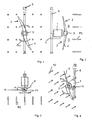
- first horizontal agitator is a submersible motor 1 in an axial arrangement with a propeller 2 drivingly connected.
- the propeller 2 has two blades 4 extending radially from a hub 3.
- the submersible motor 1 is accommodated on a carriage 5 which can be moved vertically on a column-like frame 6 by means of a vertical movement device (not shown here).
- a vertical movement device is, for. B. in the DE 40 15 478 C1 described.
- second horizontal agitator radially outboard end portions 7 of the blades 4 are bent in a direction opposite to the direction indicated by the second arrows P2 main flow direction.
- the aforementioned horizontal main flow direction P2 extends substantially parallel to the likewise horizontally extending axis of rotation of the propeller 2.
- a bending angle ⁇ with respect to a radial plane R here is about 55 °.
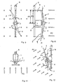
- the bending angle ⁇ can also be larger or smaller, and preferably in a range between 30 and 90 °.
- the end portions 7 have a length which corresponds to at most one fifth of the radius of the blades 4.
- the end sections 7 extend only over a tenth of the radial length of the blades 4.
- end sections 7 have a curvature running opposite to the direction of rotation of the rotor 2 indicated by the arrows P1.
- the proposed curvature counteracts trapping of braid-forming contaminants.
- the Fig. 9 to 12 show a third horizontal agitator, in which the propeller 2 is formed as in the second horizontal agitator.
- the propeller 2 in turn has bent end sections 7.
- third horizontal agitator are downstream of the propeller 2 in a plane extending through the axis of rotation of the propeller 2 axial plane extending plate-shaped flow guide elements 8 are provided.
- the flow guide elements 8 are mounted on the columnar frame 6 in the embodiment shown. Of course, it is also possible to attach the flow guide elements 8 on the submersible motor 1 or on the carriage 5.
- the flow guide elements 8 extend from the submersible motor 1 in the radial direction to a first radius R1, which is greater than or equal to a second radius R2 of the propeller 2.
- the first radius R1 may preferably be 1.0 to 1.3 times the second radius R2.
- leading edges 9 are inclined relative to the radial plane R.
- An inclination angle ⁇ opens radially outwards and is preferably 5 to 25 °.
- a curved leading edge 9 may be provided, whose curvature is directed in the main flow direction P2.
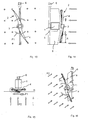
- a drive device may be provided, which in addition to the submersible motor 1 comprises a transmission.
- FIGS. 13 to 17 show views of a fourth horizontal agitator.
- the blades 4 of the propeller 2 are made of a composite material, in which fibers are accommodated in a plastic matrix.
- the elasticity of the blades 4 is set so that, in particular, an outer portion A elastically deforms under the influence of a fluid pressure.
- suitable Material design is the elastic deformation so that a Profilanstellwinkel the outer portion A relative to the perpendicular through the axis of rotation extending radial plane R with increasing fluid pressure is greater.
- an outer portion A of the blades 4 entrenches with increasing fluid pressure or with increasing speed.
- a first angle ⁇ 1 represents the shape of the blades at a low speed
- a second angle ⁇ 2 the shape of the blades at a medium speed
- a third angle ⁇ 3 at a high speed again.
- different fibers for example carbon and / or aramid and / or highly stretched polyethylene fibers, can be combined with one another.
- the desired elastic properties can also be influenced by the orientation and the number of fiber layers as well as by the thickness of the profile.
- the propeller has a total weight, which corresponds to the volume of water or wastewater displaced by its volume. Ie.
- the propeller is so heavy that it does not buoy in the submerged state.
- the composite material may be provided with metallic particles or metallic inserts, which are made of lead, for example.
Claims (21)
- Agitateur horizontal pour produire un courant dans un bassin de décantation, selon lequel une hélice (2) présentant plusieurs pales (4) est reliée à un moteur submersible (1) disposé avec un décalage axial par rapport à elle, l'hélice (2) et le moteur submersible (1) étant conçus de telle sorte qu'un courant (P2) dirigé de l'hélice (2) vers le moteur submersible (1) est produit lors du fonctionnement du moteur submersible (1),
caractérisé en ce que
des segments d'extrémité (7) extérieurs radiaux des pales (4) sont recourbés dans une direction opposée au sens du courant principal axial (P2) produit par l'hélice. - Agitateur horizontal selon la revendication 1, où une déformation élastique des pales (4) réalisées en un matériau élastique déformable est définie de façon telle que leur angle d'attaque de profil (α1, α2, α3) tout au moins dans la zone d'un segment extérieur radial (A) s'agrandit de manière prédéfinie à une vitesse de rotation croissante.
- Agitateur horizontal selon l'une des revendications précédentes, où les pales (4) sont réalisées en un matériau composite renforcé de fibres.
- Agitateur horizontal selon la revendication 3, où une matrice du matériau composite est réalisée en matière plastique.
- Agitateur horizontal selon l'une de la revendication 3 ou 4, où le matériau composite contient comme fibres des fibres de carbone et/ou d'aramide et/ou des fibres de polyéthylène très étirées.
- Agitateur horizontal selon l'une des revendications 3 à 5, où une déformation élastique des pales (4) est définie par le choix, la quantité et la disposition des fibres.
- Agitateur horizontal selon l'une des revendications 2 ou 6, où la déformation élastique est définie par l'épaisseur du profilé.
- Agitateur horizontal selon l'une des revendications précédentes, où l'hélice (2) présente une densité dans la zone comprise entre 0,9 et 1,1 g/cm3.
- Agitateur horizontal selon l'une des revendications précédentes, où les segments d'extrémité (7) recourbés présentent une courbure opposée au sens de rotation (P1) de l'hélice (2) dans un plan radial (R).
- Agitateur horizontal selon l'une des revendications précédentes, où une longueur du segment d'extrémité (7) est égale au maximum à 1/5 du rayon (R2) de la pale (4).
- Agitateur horizontal selon l'une des revendications précédentes, où le moteur submersible (1) est monté axialement par rapport à l'hélice (2).
- Agitateur horizontal selon l'une des revendications précédentes, où deux hélices (2) tournant en sens opposé autour du même axe de rotation sont prévues pour la production du courant (P2) dirigé vers le moteur submersible (1).
- Agitateur horizontal selon l'une des revendications précédentes, où en aval d'au moins une hélice (2) des éléments de guidage de courant (8) de forme plate s'étendant dans au moins un plan axial sont prévus.
- Agitateur horizontal selon la revendication 13, où les éléments de guidage de courant (8) sont réalisés à partir d'une tôle ou en matière plastique renforcée de fibres.
- Agitateur horizontal selon l'une des revendications 13 ou 14, où les éléments de guidage de courant (8) s'étendent dans un plan vertical et/ou dans un plan horizontal.
- Agitateur horizontal selon l'une des revendications 13 à 15, où les éléments de guidage de courant (8) sont montés sur le moteur submersible (1) ou sur un dispositif d'entraînement comprenant le moteur submersible (1).
- Agitateur horizontal selon l'une des revendications précédentes, où le moteur submersible (1) ou le dispositif d'entraînement est fixé sur un dispositif de déplacement vertical (5) prévu sur un bâti (6).
- Agitateur horizontal selon la revendication 17, où les éléments de guidage de courant (8) sont montés sur le bâti (6) logeant le moteur submersible (1).
- Agitateur horizontal selon l'une des revendications 13 à 16 ou 18, où un bord d'attaque (9) des éléments de guidage de courant (8) présente une inclinaison (γ) ou courbure dirigée dans le sens du courant principal (P2) à une distance radiale croissante.
- Dispositif pour la décantation d'eaux usées avec un bassin de décantation et au moins un agitateur horizontal logé à l'intérieur de ce dernier selon l'une des revendications précédentes.
- Procédé pour produire un courant dans un bassin de décantation avec un agitateur horizontal, selon lequel une hélice (2) présentant plusieurs pales (4) est reliée à un moteur submersible (1) disposé axialement par rapport à elle, l'hélice (2) tournant avec le moteur submersible (1) de façon telle qu'un courant (P2) dirigé de l'hélice (2) vers le moteur submersible (1) est produit,
caractérisé en ce que
un agitateur horizontal pour la production du courant (P2) est utilisé selon l'une des revendications 1 à 19.
Priority Applications (1)
| Application Number | Priority Date | Filing Date | Title |
|---|---|---|---|
| PL08715766T PL2125179T3 (pl) | 2007-02-19 | 2008-02-14 | Mieszalnik poziomy i sposób wytwarzania przepływu w zbiorniku osadnikowym z mieszalnikiem poziomym |
Applications Claiming Priority (2)
| Application Number | Priority Date | Filing Date | Title |
|---|---|---|---|
| DE102007008134A DE102007008134A1 (de) | 2007-02-19 | 2007-02-19 | Horizontalrührwerk und Verfahren zum Erzeugen einer Strömung in einem Klärbecken mit dem Horizontalrührwerk |
| PCT/EP2008/001128 WO2008101632A1 (fr) | 2007-02-19 | 2008-02-14 | Agitateur horizontal et procédé pour produire un courant dans un bassin de décantation avec l'agitateur horizontal |
Publications (2)
| Publication Number | Publication Date |
|---|---|
| EP2125179A1 EP2125179A1 (fr) | 2009-12-02 |
| EP2125179B1 true EP2125179B1 (fr) | 2011-01-12 |
Family
ID=39415107
Family Applications (1)
| Application Number | Title | Priority Date | Filing Date |
|---|---|---|---|
| EP20080715766 Active EP2125179B1 (fr) | 2007-02-19 | 2008-02-14 | Agitateur horizontal et procédé pour produire un courant dans un bassin de décantation avec l'agitateur horizontal |
Country Status (10)
| Country | Link |
|---|---|
| US (1) | US8210738B2 (fr) |
| EP (1) | EP2125179B1 (fr) |
| JP (1) | JP2010519021A (fr) |
| CN (1) | CN101616728B (fr) |
| AT (1) | ATE494950T1 (fr) |
| DE (2) | DE102007008134A1 (fr) |
| DK (1) | DK2125179T3 (fr) |
| ES (1) | ES2358630T3 (fr) |
| PL (1) | PL2125179T3 (fr) |
| WO (1) | WO2008101632A1 (fr) |
Families Citing this family (10)
| Publication number | Priority date | Publication date | Assignee | Title |
|---|---|---|---|---|
| DE502008002387D1 (de) * | 2007-02-19 | 2011-03-03 | Invent Umwelt & Verfahrenstech | Horizontalrührwerk und einrichtung zum erzeugen einer strömung in einem klärbecken mit dem horizontalrührwerk |
| DE102007008134A1 (de) * | 2007-02-19 | 2008-08-21 | Invent Umwelt- Und Verfahrenstechnik Ag | Horizontalrührwerk und Verfahren zum Erzeugen einer Strömung in einem Klärbecken mit dem Horizontalrührwerk |
| BRPI0812160A2 (pt) * | 2007-05-23 | 2014-12-16 | Nestec Sa | Equipamento para o condicionamento de um líquido a base de leite |
| SE531903C2 (sv) * | 2008-01-11 | 2009-09-08 | Itt Mfg Enterprises Inc | Omrörarsammansättning och metod för flödesstyrning i en omrörarsammansättning |
| DE102012204724A1 (de) * | 2012-03-23 | 2013-09-26 | Invent Umwelt-Und Verfahrenstechnik Ag | Anordnung und Verfahren zum Erzeugen einer Strömung in einem Abwasserbehandlungsbecken |
| DE102012205269A1 (de) | 2012-03-30 | 2013-10-02 | Invent Umwelt- Und Verfahrenstechnik Ag | Horizontalrührwerk |
| DE102012205579A1 (de) | 2012-04-04 | 2013-10-10 | Invent Umwelt-Und Verfahrenstechnik Ag | Horizontalrührwerk |
| DE102012205577B3 (de) | 2012-04-04 | 2013-06-06 | Invent Umwelt-Und Verfahrenstechnik Ag | Horizontalrührwerk |
| EP2689830B1 (fr) * | 2012-07-26 | 2016-04-20 | Michael Niederbacher | Installation de biogaz |
| US10618629B2 (en) | 2016-08-09 | 2020-04-14 | Gopro, Inc. | Automated variable pitch propeller blade |
Family Cites Families (18)
| Publication number | Priority date | Publication date | Assignee | Title |
|---|---|---|---|---|
| US3108146A (en) * | 1959-09-16 | 1963-10-22 | George E Gross | Fluid handling device |
| NL184075B (nl) * | 1978-06-30 | 1988-11-01 | Hva Water Contractors B V | Werkwijze voor het bedrijven van een om een draaiingsas draaibare rotor, alsmede rotor bestemd voor het uitvoeren van een dergelijke werkwijze. |
| US4627791A (en) | 1982-11-10 | 1986-12-09 | Marshall Andrew C | Aeroelastically responsive composite propeller |
| JPS6015149A (ja) * | 1983-07-07 | 1985-01-25 | 三菱重工業株式会社 | 海洋構造体とその製造方法 |
| US4566801A (en) | 1984-10-18 | 1986-01-28 | General Signal Corporation | Submersible mixer alignable in a horizontal or vertical mode |
| US4722608A (en) * | 1985-07-30 | 1988-02-02 | General Signal Corp. | Mixing apparatus |
| SE8600369D0 (sv) * | 1986-01-28 | 1986-01-28 | Stromberg Karl Otto | Propeller jemte sett att framstella en sadan |
| US4671872A (en) * | 1986-03-18 | 1987-06-09 | Air-O-Lator Corporation | Aerator mast with azimuth lock and bottom stop |
| DE3931918A1 (de) * | 1989-06-19 | 1991-01-03 | Streisal Tauchmotor Gmbh | Tauchruehrwerk |
| DE4015478C1 (fr) | 1990-05-14 | 1991-09-12 | Abs Pumpen Ag, 5204 Lohmar, De | |
| US5993158A (en) | 1997-10-17 | 1999-11-30 | Dbs Manufacturing, Inc. | Method and apparatus for aeration using flexible blade impeller |
| JPH11197687A (ja) * | 1998-01-13 | 1999-07-27 | Mitsubishi Heavy Ind Ltd | 水流発生装置 |
| US6231268B1 (en) * | 1999-04-19 | 2001-05-15 | Limnetics Corporation | Apparatus and method for treatment of large water bodies by directed circulation |
| JP2002346359A (ja) * | 2001-05-29 | 2002-12-03 | Shin Meiwa Ind Co Ltd | プロペラ及び水中ミキサ |
| JP4316175B2 (ja) * | 2001-12-20 | 2009-08-19 | 株式会社鶴見製作所 | 汚水処理槽内の攪拌装置 |
| JP2003327196A (ja) * | 2002-05-15 | 2003-11-19 | Hiroboo Kk | 模型ボート用のアウトドライブ装置 |
| DE502008002387D1 (de) * | 2007-02-19 | 2011-03-03 | Invent Umwelt & Verfahrenstech | Horizontalrührwerk und einrichtung zum erzeugen einer strömung in einem klärbecken mit dem horizontalrührwerk |
| DE102007008134A1 (de) * | 2007-02-19 | 2008-08-21 | Invent Umwelt- Und Verfahrenstechnik Ag | Horizontalrührwerk und Verfahren zum Erzeugen einer Strömung in einem Klärbecken mit dem Horizontalrührwerk |
-
2007
- 2007-02-19 DE DE102007008134A patent/DE102007008134A1/de not_active Ceased
-
2008
- 2008-02-14 WO PCT/EP2008/001128 patent/WO2008101632A1/fr active Application Filing
- 2008-02-14 AT AT08715766T patent/ATE494950T1/de active
- 2008-02-14 DE DE200850002285 patent/DE502008002285D1/de active Active
- 2008-02-14 CN CN2008800054485A patent/CN101616728B/zh active Active
- 2008-02-14 DK DK08715766T patent/DK2125179T3/da active
- 2008-02-14 JP JP2009550233A patent/JP2010519021A/ja active Pending
- 2008-02-14 ES ES08715766T patent/ES2358630T3/es active Active
- 2008-02-14 US US12/449,325 patent/US8210738B2/en active Active
- 2008-02-14 EP EP20080715766 patent/EP2125179B1/fr active Active
- 2008-02-14 PL PL08715766T patent/PL2125179T3/pl unknown
Also Published As
| Publication number | Publication date |
|---|---|
| DE502008002285D1 (de) | 2011-02-24 |
| EP2125179A1 (fr) | 2009-12-02 |
| JP2010519021A (ja) | 2010-06-03 |
| CN101616728A (zh) | 2009-12-30 |
| US20100096343A1 (en) | 2010-04-22 |
| DE102007008134A1 (de) | 2008-08-21 |
| DK2125179T3 (da) | 2011-04-26 |
| WO2008101632A1 (fr) | 2008-08-28 |
| ES2358630T3 (es) | 2011-05-12 |
| PL2125179T3 (pl) | 2011-10-31 |
| ATE494950T1 (de) | 2011-01-15 |
| CN101616728B (zh) | 2013-06-12 |
| US8210738B2 (en) | 2012-07-03 |
Similar Documents
| Publication | Publication Date | Title |
|---|---|---|
| EP2125179B1 (fr) | Agitateur horizontal et procédé pour produire un courant dans un bassin de décantation avec l'agitateur horizontal | |
| EP2125180B1 (fr) | Agitateur horizontal et dispositif pour produire un courant dans un bassin de décantation avec l'agitateur horizontal | |
| DE2458841C2 (de) | Rührwerksmühle | |
| DE102011118844B3 (de) | Vertikalwindturbine und Rotorblatt hierfür | |
| DE202010004056U1 (de) | Schneckenkörper für eine Wasserkraftanlage | |
| DE102007008136B4 (de) | Horizontalrührwerk zum Erzeugen einer Strömung in einem Klärbecken und dessen Verwendung | |
| DE102005049794A1 (de) | Propeller | |
| EP2372163A1 (fr) | Roue de ventilateur | |
| EP2480321B1 (fr) | Élément de malaxage à effet axial | |
| DE2334304A1 (de) | Ventilatorschaufel fuer tangentiale geblaeselueftung | |
| EP2830750B1 (fr) | Agitateur horizontal | |
| EP1847337B1 (fr) | Système d'entraînement d'un rotor d'une machine à dresser pour le dressage des fils métalliques | |
| DE10340112A1 (de) | Windkraftanlage | |
| DE3111505A1 (de) | Verfahren zur herstellung eines schraubengewindes, insbesondere fuer ein schneckengetriebe und nach diesem verfahren hergestellte schraube | |
| DE202017007195U1 (de) | Lüfterrad | |
| DE102010022070A1 (de) | Antriebseinheit | |
| DE102012205577B3 (de) | Horizontalrührwerk | |
| DE897470C (de) | Laeufer fuer Schleuderverdichter mit diagonalem Stroemungsverlauf | |
| DE102017203525A1 (de) | Lüfterrad | |
| DE112014006805T5 (de) | Rotor für eine Abluftventilatoranordnung einer Landwirtschaftsmaschine | |
| DE102015219331A1 (de) | Radiales Laufrad | |
| CH350935A (de) | Verfahren zum Belüften von Flüssigkeiten und Belüftungsrotor zur Durchführung des Verfahrens | |
| DE202017007196U1 (de) | Lüfterrad | |
| DE202023106188U1 (de) | Impeller mit Außenantrieb für ein Luftfahrzeug | |
| DE102022111409A1 (de) | Schneckenwelle für einen Schneckenabscheider |
Legal Events
| Date | Code | Title | Description |
|---|---|---|---|
| PUAI | Public reference made under article 153(3) epc to a published international application that has entered the european phase |
Free format text: ORIGINAL CODE: 0009012 |
|
| 17P | Request for examination filed |
Effective date: 20090821 |
|
| AK | Designated contracting states |
Kind code of ref document: A1 Designated state(s): AT BE BG CH CY CZ DE DK EE ES FI FR GB GR HR HU IE IS IT LI LT LU LV MC MT NL NO PL PT RO SE SI SK TR |
|
| DAX | Request for extension of the european patent (deleted) | ||
| GRAP | Despatch of communication of intention to grant a patent |
Free format text: ORIGINAL CODE: EPIDOSNIGR1 |
|
| GRAS | Grant fee paid |
Free format text: ORIGINAL CODE: EPIDOSNIGR3 |
|
| GRAA | (expected) grant |
Free format text: ORIGINAL CODE: 0009210 |
|
| RIN1 | Information on inventor provided before grant (corrected) |
Inventor name: HOEFKEN, MARCUS |
|
| AK | Designated contracting states |
Kind code of ref document: B1 Designated state(s): AT BE BG CH CY CZ DE DK EE ES FI FR GB GR HR HU IE IS IT LI LT LU LV MC MT NL NO PL PT RO SE SI SK TR |
|
| REG | Reference to a national code |
Ref country code: GB Ref legal event code: FG4D Free format text: NOT ENGLISH |
|
| REG | Reference to a national code |
Ref country code: CH Ref legal event code: EP |
|
| REG | Reference to a national code |
Ref country code: IE Ref legal event code: FG4D Free format text: LANGUAGE OF EP DOCUMENT: GERMAN |
|
| REF | Corresponds to: |
Ref document number: 502008002285 Country of ref document: DE Date of ref document: 20110224 Kind code of ref document: P |
|
| REG | Reference to a national code |
Ref country code: DE Ref legal event code: R096 Ref document number: 502008002285 Country of ref document: DE Effective date: 20110224 |
|
| REG | Reference to a national code |
Ref country code: SE Ref legal event code: TRGR Ref country code: DK Ref legal event code: T3 |
|
| REG | Reference to a national code |
Ref country code: NL Ref legal event code: T3 |
|
| REG | Reference to a national code |
Ref country code: ES Ref legal event code: FG2A Ref document number: 2358630 Country of ref document: ES Kind code of ref document: T3 Effective date: 20110429 |
|
| LTIE | Lt: invalidation of european patent or patent extension |
Effective date: 20110112 |
|
| PG25 | Lapsed in a contracting state [announced via postgrant information from national office to epo] |
Ref country code: LT Free format text: LAPSE BECAUSE OF FAILURE TO SUBMIT A TRANSLATION OF THE DESCRIPTION OR TO PAY THE FEE WITHIN THE PRESCRIBED TIME-LIMIT Effective date: 20110112 Ref country code: GR Free format text: LAPSE BECAUSE OF FAILURE TO SUBMIT A TRANSLATION OF THE DESCRIPTION OR TO PAY THE FEE WITHIN THE PRESCRIBED TIME-LIMIT Effective date: 20110413 Ref country code: NO Free format text: LAPSE BECAUSE OF FAILURE TO SUBMIT A TRANSLATION OF THE DESCRIPTION OR TO PAY THE FEE WITHIN THE PRESCRIBED TIME-LIMIT Effective date: 20110412 Ref country code: PT Free format text: LAPSE BECAUSE OF FAILURE TO SUBMIT A TRANSLATION OF THE DESCRIPTION OR TO PAY THE FEE WITHIN THE PRESCRIBED TIME-LIMIT Effective date: 20110512 Ref country code: IS Free format text: LAPSE BECAUSE OF FAILURE TO SUBMIT A TRANSLATION OF THE DESCRIPTION OR TO PAY THE FEE WITHIN THE PRESCRIBED TIME-LIMIT Effective date: 20110512 Ref country code: LV Free format text: LAPSE BECAUSE OF FAILURE TO SUBMIT A TRANSLATION OF THE DESCRIPTION OR TO PAY THE FEE WITHIN THE PRESCRIBED TIME-LIMIT Effective date: 20110112 Ref country code: HR Free format text: LAPSE BECAUSE OF FAILURE TO SUBMIT A TRANSLATION OF THE DESCRIPTION OR TO PAY THE FEE WITHIN THE PRESCRIBED TIME-LIMIT Effective date: 20110112 |
|
| REG | Reference to a national code |
Ref country code: HU Ref legal event code: AG4A Ref document number: E010795 Country of ref document: HU |
|
| PG25 | Lapsed in a contracting state [announced via postgrant information from national office to epo] |
Ref country code: CY Free format text: LAPSE BECAUSE OF FAILURE TO SUBMIT A TRANSLATION OF THE DESCRIPTION OR TO PAY THE FEE WITHIN THE PRESCRIBED TIME-LIMIT Effective date: 20110112 Ref country code: BG Free format text: LAPSE BECAUSE OF FAILURE TO SUBMIT A TRANSLATION OF THE DESCRIPTION OR TO PAY THE FEE WITHIN THE PRESCRIBED TIME-LIMIT Effective date: 20110412 Ref country code: SI Free format text: LAPSE BECAUSE OF FAILURE TO SUBMIT A TRANSLATION OF THE DESCRIPTION OR TO PAY THE FEE WITHIN THE PRESCRIBED TIME-LIMIT Effective date: 20110112 |
|
| PG25 | Lapsed in a contracting state [announced via postgrant information from national office to epo] |
Ref country code: MC Free format text: LAPSE BECAUSE OF NON-PAYMENT OF DUE FEES Effective date: 20110228 |
|
| PG25 | Lapsed in a contracting state [announced via postgrant information from national office to epo] |
Ref country code: EE Free format text: LAPSE BECAUSE OF FAILURE TO SUBMIT A TRANSLATION OF THE DESCRIPTION OR TO PAY THE FEE WITHIN THE PRESCRIBED TIME-LIMIT Effective date: 20110112 |
|
| REG | Reference to a national code |
Ref country code: PL Ref legal event code: T3 |
|
| PLBE | No opposition filed within time limit |
Free format text: ORIGINAL CODE: 0009261 |
|
| STAA | Information on the status of an ep patent application or granted ep patent |
Free format text: STATUS: NO OPPOSITION FILED WITHIN TIME LIMIT |
|
| PG25 | Lapsed in a contracting state [announced via postgrant information from national office to epo] |
Ref country code: SK Free format text: LAPSE BECAUSE OF FAILURE TO SUBMIT A TRANSLATION OF THE DESCRIPTION OR TO PAY THE FEE WITHIN THE PRESCRIBED TIME-LIMIT Effective date: 20110112 Ref country code: RO Free format text: LAPSE BECAUSE OF FAILURE TO SUBMIT A TRANSLATION OF THE DESCRIPTION OR TO PAY THE FEE WITHIN THE PRESCRIBED TIME-LIMIT Effective date: 20110112 |
|
| 26N | No opposition filed |
Effective date: 20111013 |
|
| PG25 | Lapsed in a contracting state [announced via postgrant information from national office to epo] |
Ref country code: MT Free format text: LAPSE BECAUSE OF FAILURE TO SUBMIT A TRANSLATION OF THE DESCRIPTION OR TO PAY THE FEE WITHIN THE PRESCRIBED TIME-LIMIT Effective date: 20110112 |
|
| REG | Reference to a national code |
Ref country code: DE Ref legal event code: R097 Ref document number: 502008002285 Country of ref document: DE Effective date: 20111013 |
|
| PG25 | Lapsed in a contracting state [announced via postgrant information from national office to epo] |
Ref country code: LU Free format text: LAPSE BECAUSE OF NON-PAYMENT OF DUE FEES Effective date: 20110214 |
|
| PG25 | Lapsed in a contracting state [announced via postgrant information from national office to epo] |
Ref country code: TR Free format text: LAPSE BECAUSE OF FAILURE TO SUBMIT A TRANSLATION OF THE DESCRIPTION OR TO PAY THE FEE WITHIN THE PRESCRIBED TIME-LIMIT Effective date: 20110112 |
|
| REG | Reference to a national code |
Ref country code: FR Ref legal event code: PLFP Year of fee payment: 9 |
|
| REG | Reference to a national code |
Ref country code: FR Ref legal event code: PLFP Year of fee payment: 10 |
|
| REG | Reference to a national code |
Ref country code: FR Ref legal event code: PLFP Year of fee payment: 11 |
|
| REG | Reference to a national code |
Ref country code: DE Ref legal event code: R079 Ref document number: 502008002285 Country of ref document: DE Free format text: PREVIOUS MAIN CLASS: B01F0007000000 Ipc: B01F0027000000 |
|
| PGFP | Annual fee paid to national office [announced via postgrant information from national office to epo] |
Ref country code: IE Payment date: 20230215 Year of fee payment: 16 Ref country code: FR Payment date: 20230217 Year of fee payment: 16 Ref country code: FI Payment date: 20230222 Year of fee payment: 16 Ref country code: ES Payment date: 20230317 Year of fee payment: 16 Ref country code: DK Payment date: 20230220 Year of fee payment: 16 Ref country code: CZ Payment date: 20230202 Year of fee payment: 16 Ref country code: CH Payment date: 20230307 Year of fee payment: 16 Ref country code: AT Payment date: 20230215 Year of fee payment: 16 |
|
| PGFP | Annual fee paid to national office [announced via postgrant information from national office to epo] |
Ref country code: SE Payment date: 20230220 Year of fee payment: 16 Ref country code: PL Payment date: 20230207 Year of fee payment: 16 Ref country code: IT Payment date: 20230228 Year of fee payment: 16 Ref country code: BE Payment date: 20230220 Year of fee payment: 16 |
|
| PGFP | Annual fee paid to national office [announced via postgrant information from national office to epo] |
Ref country code: NL Payment date: 20240220 Year of fee payment: 17 Ref country code: ES Payment date: 20240319 Year of fee payment: 17 Ref country code: IE Payment date: 20240216 Year of fee payment: 17 |
|
| PGFP | Annual fee paid to national office [announced via postgrant information from national office to epo] |
Ref country code: AT Payment date: 20240216 Year of fee payment: 17 |
|
| PGFP | Annual fee paid to national office [announced via postgrant information from national office to epo] |
Ref country code: HU Payment date: 20240207 Year of fee payment: 17 Ref country code: FI Payment date: 20240219 Year of fee payment: 17 Ref country code: DE Payment date: 20240216 Year of fee payment: 17 Ref country code: CZ Payment date: 20240201 Year of fee payment: 17 Ref country code: GB Payment date: 20240222 Year of fee payment: 17 Ref country code: CH Payment date: 20240301 Year of fee payment: 17 |