EP2480321B1 - Élément de malaxage à effet axial - Google Patents
Élément de malaxage à effet axial Download PDFInfo
- Publication number
- EP2480321B1 EP2480321B1 EP10755165.7A EP10755165A EP2480321B1 EP 2480321 B1 EP2480321 B1 EP 2480321B1 EP 10755165 A EP10755165 A EP 10755165A EP 2480321 B1 EP2480321 B1 EP 2480321B1
- Authority
- EP
- European Patent Office
- Prior art keywords
- propeller
- blades
- stirring element
- axially operating
- blade
- Prior art date
- Legal status (The legal status is an assumption and is not a legal conclusion. Google has not performed a legal analysis and makes no representation as to the accuracy of the status listed.)
- Active
Links
- 238000003756 stirring Methods 0.000 title claims description 32
- 229910052751 metal Inorganic materials 0.000 claims description 11
- 239000002184 metal Substances 0.000 claims description 11
- 230000008719 thickening Effects 0.000 claims description 3
- 238000010276 construction Methods 0.000 description 5
- 239000000463 material Substances 0.000 description 4
- 230000008901 benefit Effects 0.000 description 3
- 238000004519 manufacturing process Methods 0.000 description 3
- 239000012530 fluid Substances 0.000 description 2
- 230000002787 reinforcement Effects 0.000 description 2
- 229910000831 Steel Inorganic materials 0.000 description 1
- 239000000956 alloy Substances 0.000 description 1
- 229910045601 alloy Inorganic materials 0.000 description 1
- 229910052782 aluminium Inorganic materials 0.000 description 1
- XAGFODPZIPBFFR-UHFFFAOYSA-N aluminium Chemical compound [Al] XAGFODPZIPBFFR-UHFFFAOYSA-N 0.000 description 1
- 230000015572 biosynthetic process Effects 0.000 description 1
- 238000005260 corrosion Methods 0.000 description 1
- 230000007797 corrosion Effects 0.000 description 1
- 238000000227 grinding Methods 0.000 description 1
- 239000003295 industrial effluent Substances 0.000 description 1
- 239000010842 industrial wastewater Substances 0.000 description 1
- 150000002739 metals Chemical class 0.000 description 1
- 238000000034 method Methods 0.000 description 1
- 238000003801 milling Methods 0.000 description 1
- 239000010841 municipal wastewater Substances 0.000 description 1
- 230000008092 positive effect Effects 0.000 description 1
- 230000008569 process Effects 0.000 description 1
- 230000009467 reduction Effects 0.000 description 1
- 239000010959 steel Substances 0.000 description 1
- 238000011144 upstream manufacturing Methods 0.000 description 1
Images


Classifications
-
- B—PERFORMING OPERATIONS; TRANSPORTING
- B21—MECHANICAL METAL-WORKING WITHOUT ESSENTIALLY REMOVING MATERIAL; PUNCHING METAL
- B21D—WORKING OR PROCESSING OF SHEET METAL OR METAL TUBES, RODS OR PROFILES WITHOUT ESSENTIALLY REMOVING MATERIAL; PUNCHING METAL
- B21D53/00—Making other particular articles
- B21D53/78—Making other particular articles propeller blades; turbine blades
-
- B—PERFORMING OPERATIONS; TRANSPORTING
- B01—PHYSICAL OR CHEMICAL PROCESSES OR APPARATUS IN GENERAL
- B01F—MIXING, e.g. DISSOLVING, EMULSIFYING OR DISPERSING
- B01F27/00—Mixers with rotary stirring devices in fixed receptacles; Kneaders
- B01F27/05—Stirrers
- B01F27/11—Stirrers characterised by the configuration of the stirrers
- B01F27/113—Propeller-shaped stirrers for producing an axial flow, e.g. shaped like a ship or aircraft propeller
-
- Y—GENERAL TAGGING OF NEW TECHNOLOGICAL DEVELOPMENTS; GENERAL TAGGING OF CROSS-SECTIONAL TECHNOLOGIES SPANNING OVER SEVERAL SECTIONS OF THE IPC; TECHNICAL SUBJECTS COVERED BY FORMER USPC CROSS-REFERENCE ART COLLECTIONS [XRACs] AND DIGESTS
- Y10—TECHNICAL SUBJECTS COVERED BY FORMER USPC
- Y10T—TECHNICAL SUBJECTS COVERED BY FORMER US CLASSIFICATION
- Y10T29/00—Metal working
- Y10T29/49—Method of mechanical manufacture
- Y10T29/49316—Impeller making
- Y10T29/49327—Axial blower or fan
Definitions
- the present invention relates to an axially acting stirring element according to claim 1.
- Axial-acting propellers are known in numerous designs from the prior art.
- the propellers used are particularly suitable for the production of from the conveyor fluid resistant, in particular corrosion-resistant, sheet materials therefor.
- propellers which have a constant or nearly constant plate or blade thickness, occur in the partially viscous media to be stirred on rotation higher power losses at the trailing edge, as with propellers with profiled blades, but the latter are much more expensive to produce. Thus, more energy must be expended to rotate the propeller at a constant, high speed through the viscous medium. It is known in the art to skew and sharpen the blades on their entry side (front) to reduce endurance losses.
- the object of the present invention is to further reduce the rotational resistance of a propeller. It can also be achieved a significant saving of the energy required for the stirring process.
- a further object of the invention is therefore to achieve an improved stirring result with constant expenditure of energy, a constant stirring result with less expenditure of energy or an improved stirring result with less expenditure of energy when using a stirring element according to the invention.
- An axially acting stirrer preferably a propeller, with blades arranged radially about an axis should therefore only have a part, preferably the outer half, particularly preferably the outer two thirds of the edge on the outlet side of the sharpened edge.
- axial stirring means are understood here Rhackorgane on which the blades are arranged radially and mostly obliquely adjusted about an axis of rotation.
- the primary flow of the stirred medium during operation of such an axial stirring element is always directed axially.
- the entry side or front side is to be understood as that edge of the blade which leads in the intended direction of rotation during operation of the stirring element.
- the outlet side or rear side is that edge of the blade which lags in the intended direction of rotation during operation of the stirring element.
- one or more blades are also sharpened at the entrance side.
- the thrust / power ratio can be improved.
- the improvements that result from a reinforcement only at the front or the back can be significantly exceeded.
- An agitator yarn according to the invention has at least one blade with the aforementioned properties.
- the increase on the inlet and / or outlet side individually has an angle of attack of between about 5 ° to about 30 °, preferably between about 10 ° to about 15 °.
- This angle of attack may have a constant angle across all blades when there are multiple blades that are sharpened on the exit side. The same applies if there are several blades which have been sharpened on the inlet side.
- the ground joint is attached to the suction side of the blades.
- the agitated medium flows through the agitator, i. the upstream side of the blades.
- the entire edge is sharpened, but only one area.
- This may preferably be the outer, i. the area further away from the axis of rotation, since here the absolute speed of the edges through the medium at the same speed is higher than in the inner area.
- the blades are treated only in the outer two-thirds or only the outer half.
- such an agitator is used with an overall diameter of between about 20 cm and about 1 m, preferably between about 30 cm and about 60 cm, and more preferably between about 30 cm and about 40 cm. In another embodiment, the overall diameter is between about 40 cm and about 80 cm.
- agitator orbital diameters greater than 1 m are also suitable for use in corresponding agitators and should justify a noticeable gain in the thrust / power ratio.
- One or more blades are made of sheet metal.
- sheet metal is to be understood as meaning a flat or nearly flat sheet of metal.
- Many metals, and especially alloys, are useful as base materials for the present application, however, in one embodiment, resistant steel sheets and aluminum sheets are particularly notable over the production fluids.
- one or more blades outside the sharpened locations has a constant thickness. This is also advantageous in terms of price, justifies a moderate weight of the propeller stirrer and has the advantage of a low rotational resistance. Sheets usually have a constant thickness over their surface.
- the blades or the material underlying the blades, preferably sheet metal are between 3 and 15 mm, preferably between 3 and 8 mm thick. These values also vary, of course, depending on the application and R
- one or more blades are arched.
- This construction is advantageous in the case of a propeller stirrer in order to justify an axial axis which is as large as possible in the direction of flow of the stirred medium.
- the curvature of the curvature at each point of the blade has a uniform sign or is 0.
- the curvature is such that the blades, at the location of attachment to the shaft, are angled in relation to the direction of rotation and at the outer ends have a position along the direction of rotation.
- the sheet used for the construction of the propeller is bent to the shape of a blade and welded to a propeller hub.
- One or more blades are sickle-shaped.
- This crescent-shaped shape can be formed both from the shape of the non-arched material, preferably the sheet yield, or in the plan view of the blades along the axis of rotation.
- the blades do not converge on the outside in a pointed manner, but are rounded off or obliquely or tangentially cut off. Such a design results in a high stability of the blades into their end region and less turbulence formation.
- At least two blades are designed such that their size, their distance and / or their shape that superimpose individual blades in a plan view in the direction of the axis of rotation.
- all blades Preferably, all blades have the same distance, but at least a regular distance pattern to each other.
- the preferred number of blades of a propeller according to the invention is generally between 2 and about 10 blades, preferably between 2 and 5 blades and more preferably with exactly 3 blades.
- the blades have a width of between about 5 cm and about 30 cm, preferably between about 10 cm and about 25 cm, over their length (about D / 2), which is determined closer above the diameter. This size can relate both to the width of the sheet before the bend and to the width of the propeller when viewed from the axial direction.
- propellers can be introduced centrically or eccentrically into a medium to be mixed or stirred. Several such propellers within a medium are also conceivable.
- the propeller can be introduced along an axis perpendicular from above or from below into the target area or laterally, obliquely or angled.
- a further aspect of the invention is the use of a stirring element just described.
- a stirring element is used in an agitator for stirring and / or mixing.
- the use is preferably provided in a mixer or a submersible mixer, particularly preferably for mixing, homogenizing and thickening of preferably municipal and / or industrial wastewaters or sludges.
- the propeller is between about 100 and about 1500 Experiments revolutions per minute, preferably between about 500 and about 1000 revolutions per minute.
- An exemplary maximum drive power for industrial use should be about 5 kW.
- Such a propeller is preferably operated with an electric motor.
- the invention also includes such agitators, which are suitable for the just mentioned application and have an inventive stirring element.
- FIG. 1 shows a propeller mixer with a propeller according to the invention.
- the propeller 1 is attached to the propeller hub 2 along an axis A.
- the blades 3 are curved. They show an inlet side 4 and an outlet side 5, and are cut off at their outer ends 6. Both the edge on the inlet side 4 and the edge on the outlet side 5 are sharpened.
- FIG. 1a wherein the same propeller is shown without an increase at the trailing edge.
- Such a propeller corresponds to the prior art.
- FIG. 2 shows a representation of a section of a propeller according to the invention.
- This prototype was fabricated by milling the exit side based on the Amamix 300 model of KSB Aktiengesellschaft. Particularly blade 3a is clearly visible. Blade 3a in this illustration is a blade from a second inverted propeller FIG. 1a hung up.
- the propeller hub 2 and the propeller hub 2.1 of the prior art propeller are adjacent to each other.
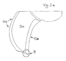
- FIG. 2a shows a representation of a section of a propeller according to the invention in the form of a single blade 3a.
- the convexly curved part 4a of the sickle-shaped blade 3a represents the entrance side and the concavely curved part 5a the exit side. It can be clearly seen that the blade was chamfered on the exit side (emphasis B). The two-sided increase the stirring resistance is significantly reduced and achieved an improved thrust / power ratio.
- FIG. 3 shows the cross section of a blade of a propeller according to the invention.
- the blade 3 is for simplicity's sake in cross section straight, that is not shown curved.
- the inlet side 4 and the outlet side 5 are sharpened according to the angles ⁇ and ⁇ . These angles may be individually in the general part of the application issued range for the cutting angle.
- the top 7 and the bottom 8 are parallel to each other and the blade 3 has over its entire width a uniform thickness d. It is also contemplated in this embodiment that the blade over its entire surface has a uniform thickness d.
- the strength is in FIG. 3 as the size d, and preferably moves within the range given in the general part of the description.
- FIG. 3a shows the cross section of a blade of the prior art.
- the angle ⁇ is about 90 ° herein.
- the edge on the exit side is not sharpened.
Landscapes
- Engineering & Computer Science (AREA)
- Aviation & Aerospace Engineering (AREA)
- Chemical & Material Sciences (AREA)
- Chemical Kinetics & Catalysis (AREA)
- Mechanical Engineering (AREA)
- Mixers Of The Rotary Stirring Type (AREA)
- Structures Of Non-Positive Displacement Pumps (AREA)
Claims (9)
- Organe d'agitation à effet axial, de préférence hélice en tôle (1) comprenant des pales d'hélice (3) disposées radialement autour d'un axe (A), une ou plusieurs pales d'hélice (3) étant formées en tôle, la tôle étant cintrée à la forme des pales et étant soudée au niveau d'un moyeu d'hélice (2), une ou plusieurs pales étant formées en forme de croissant et étant arrondies de préférence au niveau des extrémités extérieures (6) ou étant découpées obliquement ou tangentiellement, au moins deux pales individuelles étant superposées en vue de dessus dans la direction de l'axe, l'organe d'agitation présentant au moins une pale d'hélice possédant au niveau du côté de sortie (5) une arête vive,
caractérisé en ce que
seulement une partie, de préférence la moitié extérieure, particulièrement préférablement les deux tiers extérieurs de l'arête au niveau du côté de sortie présentent l'arête vive. - Organe d'agitation à effet axial, de préférence hélice, selon la revendication 1, dans lequel l'au moins une pale d'hélice possède également une arête vive au niveau du côté d'entrée (4).
- Organe d'agitation à effet axial, de préférence hélice, selon l'une quelconque des revendications précédentes, dans lequel plusieurs et de préférence la totalité des pales d'hélice de l'organe d'agitation présentent des arêtes vives au niveau du côté d'entrée et/ou du côté de sortie.
- Organe d'agitation à effet axial, de préférence hélice, selon l'une quelconque des revendications précédentes, dans lequel la partie acérée au niveau du côté d'entrée et/ou de sortie présente individuellement un angle d'attaque compris entre 5° et 30°, de préférence entre 10° et 15°.
- Organe d'agitation à effet axial, de préférence hélice, selon l'une quelconque des revendications 3 ou 4, dans lequel la partie acérée au niveau du côté d'entrée et/ou de sortie présente un angle constant sur toutes les pales d'hélice.
- Organe d'agitation à effet axial, de préférence hélice, selon l'une quelconque des revendications précédentes, dans lequel une ou plusieurs pales sont fabriquées en tôle.
- Organe d'agitation à effet axial, de préférence hélice, selon l'une quelconque des revendications précédentes, dans lequel une ou plusieurs pales à l'extérieur des zones acérées présentent une épaisseur constante.
- Mécanisme d'agitation pour agiter et/ou malaxer, de préférence malaxeur ou mécanisme d'agitation à moteur immergé comprenant un organe d'agitation selon l'une quelconque des revendications précédentes.
- Mécanisme d'agitation selon la revendication 8, pour malaxer, homogénéiser et épaissir des eaux usées ou des boues de préférence communales et/ou industrielles.
Priority Applications (1)
| Application Number | Priority Date | Filing Date | Title |
|---|---|---|---|
| PL10755165T PL2480321T3 (pl) | 2009-09-24 | 2010-09-20 | Element mieszający, działający osiowo |
Applications Claiming Priority (3)
| Application Number | Priority Date | Filing Date | Title |
|---|---|---|---|
| DE102009042843 | 2009-09-24 | ||
| DE102010044423A DE102010044423A1 (de) | 2009-09-24 | 2010-09-04 | Axialwirkendes Rührorgan, vorzugsweise ein aus Blech gefertigter Propeller |
| PCT/EP2010/063777 WO2011036113A2 (fr) | 2009-09-24 | 2010-09-20 | Élément de malaxage à effet axial, en particulier hélice fabriquée en tôle |
Publications (2)
| Publication Number | Publication Date |
|---|---|
| EP2480321A2 EP2480321A2 (fr) | 2012-08-01 |
| EP2480321B1 true EP2480321B1 (fr) | 2015-04-15 |
Family
ID=43705865
Family Applications (1)
| Application Number | Title | Priority Date | Filing Date |
|---|---|---|---|
| EP10755165.7A Active EP2480321B1 (fr) | 2009-09-24 | 2010-09-20 | Élément de malaxage à effet axial |
Country Status (12)
| Country | Link |
|---|---|
| US (1) | US20120188843A1 (fr) |
| EP (1) | EP2480321B1 (fr) |
| CN (1) | CN102510773A (fr) |
| AU (1) | AU2010299998B2 (fr) |
| BR (1) | BR112012006425A2 (fr) |
| CA (1) | CA2775123C (fr) |
| DE (1) | DE102010044423A1 (fr) |
| DK (1) | DK2480321T3 (fr) |
| ES (1) | ES2541599T3 (fr) |
| PL (1) | PL2480321T3 (fr) |
| RU (1) | RU2559501C2 (fr) |
| WO (1) | WO2011036113A2 (fr) |
Families Citing this family (2)
| Publication number | Priority date | Publication date | Assignee | Title |
|---|---|---|---|---|
| US9962665B2 (en) | 2012-06-20 | 2018-05-08 | Philadelphia Mixing Solutions, Ltd. | High efficiency, non-ragging, formed axial impeller |
| US11596907B1 (en) | 2019-06-14 | 2023-03-07 | Aeration Industries International, Llc | Apparatus for treating fluids having improved aeration efficiency and operational durability |
Family Cites Families (19)
| Publication number | Priority date | Publication date | Assignee | Title |
|---|---|---|---|---|
| US2293183A (en) * | 1939-04-03 | 1942-08-18 | American Well Works | Mixing turbine |
| US2336303A (en) * | 1941-08-04 | 1943-12-07 | Frank H Schubert | Method of making fans |
| US2799919A (en) * | 1951-11-01 | 1957-07-23 | Gen Motors Corp | Sheet metal blade and manufacture |
| GB786727A (en) * | 1954-05-11 | 1957-11-27 | Edward Archibald Stalker | Method and apparatus for making hollow blades for compressors and gas turbines |
| US3184833A (en) * | 1956-02-01 | 1965-05-25 | Borg Warner | Method of making vanes for hydraulic couplings |
| US4240990A (en) * | 1979-04-10 | 1980-12-23 | Aeration Industries, Inc. | Aeration propeller and apparatus |
| SU1197717A1 (ru) * | 1984-01-13 | 1985-12-15 | Государственный научно-исследовательский и проектный институт по обогащению руд цветных металлов "Казмеханобр" | Диспергатор |
| GB8617569D0 (en) * | 1986-07-18 | 1986-08-28 | Davidson J F | Impellers |
| US5211924A (en) * | 1988-02-29 | 1993-05-18 | Amoco Corporation | Method and apparatus for increasing conversion efficiency and reducing power costs for oxidation of an aromatic alkyl to an aromatic carboxylic acid |
| US5052892A (en) * | 1990-01-29 | 1991-10-01 | Chemineer, Inc. | High efficiency mixer impeller |
| US5297938A (en) * | 1990-03-26 | 1994-03-29 | Philadelphia Mixers Corporation | Hydrofoil impeller |
| US5100240A (en) * | 1990-05-11 | 1992-03-31 | Alterio Joseph C D | High-speed continuous mixer for solids and liquids |
| SU1761244A1 (ru) * | 1990-07-02 | 1992-09-15 | Днепропетровский инженерно-строительный институт | Устройство дл получени пенного аэрозол |
| US5158434A (en) * | 1990-07-26 | 1992-10-27 | General Signal Corporation | Mixing impellers and impeller systems for mixing and blending liquids and liquid suspensions having a wide range of viscosities |
| DE4226498A1 (de) * | 1992-08-11 | 1994-02-17 | Klein Schanzlin & Becker Ag | Rührwerkspropeller |
| US5344235A (en) * | 1993-01-21 | 1994-09-06 | General Signal Corp. | Erosion resistant mixing impeller |
| US6550703B2 (en) * | 2001-03-29 | 2003-04-22 | Hamilton Beach/Proctor-Silex, Inc. | Blender cutter |
| US6866414B2 (en) * | 2001-05-22 | 2005-03-15 | Jv Northwest, Inc. | Sanitary mixing assembly for vessels and tanks |
| CN201316604Y (zh) * | 2008-12-02 | 2009-09-30 | 北京矿冶研究总院 | 一种叶轮式搅拌装置 |
-
2010
- 2010-09-04 DE DE102010044423A patent/DE102010044423A1/de not_active Withdrawn
- 2010-09-20 WO PCT/EP2010/063777 patent/WO2011036113A2/fr active Application Filing
- 2010-09-20 ES ES10755165.7T patent/ES2541599T3/es active Active
- 2010-09-20 CA CA2775123A patent/CA2775123C/fr active Active
- 2010-09-20 PL PL10755165T patent/PL2480321T3/pl unknown
- 2010-09-20 RU RU2012114482/05A patent/RU2559501C2/ru not_active Application Discontinuation
- 2010-09-20 BR BR112012006425-8A patent/BR112012006425A2/pt not_active Application Discontinuation
- 2010-09-20 DK DK10755165.7T patent/DK2480321T3/en active
- 2010-09-20 EP EP10755165.7A patent/EP2480321B1/fr active Active
- 2010-09-20 CN CN2010800426413A patent/CN102510773A/zh active Pending
- 2010-09-20 AU AU2010299998A patent/AU2010299998B2/en not_active Ceased
-
2012
- 2012-03-23 US US13/428,217 patent/US20120188843A1/en not_active Abandoned
Also Published As
| Publication number | Publication date |
|---|---|
| CA2775123A1 (fr) | 2011-03-31 |
| ES2541599T3 (es) | 2015-07-22 |
| RU2012114482A (ru) | 2013-10-27 |
| WO2011036113A2 (fr) | 2011-03-31 |
| AU2010299998B2 (en) | 2013-11-07 |
| CA2775123C (fr) | 2017-10-24 |
| PL2480321T3 (pl) | 2015-10-30 |
| RU2559501C2 (ru) | 2015-08-10 |
| WO2011036113A3 (fr) | 2011-05-19 |
| AU2010299998A1 (en) | 2012-04-12 |
| EP2480321A2 (fr) | 2012-08-01 |
| DE102010044423A1 (de) | 2011-04-07 |
| BR112012006425A2 (pt) | 2020-11-03 |
| CN102510773A (zh) | 2012-06-20 |
| US20120188843A1 (en) | 2012-07-26 |
| DK2480321T3 (en) | 2015-06-29 |
Similar Documents
| Publication | Publication Date | Title |
|---|---|---|
| EP0112932B1 (fr) | Ventilateur radial avec des aubes profilées courbées en arrière | |
| DE69108621T2 (de) | Mischerlaufrad mit hohem wirkungsgrad. | |
| DE2624991C2 (de) | Flügelrührer | |
| EP3171970B1 (fr) | Dispositif d'organe d'agitation | |
| EP2125179B1 (fr) | Agitateur horizontal et procédé pour produire un courant dans un bassin de décantation avec l'agitateur horizontal | |
| EP1475145B1 (fr) | Agitateur | |
| EP2125180B1 (fr) | Agitateur horizontal et dispositif pour produire un courant dans un bassin de décantation avec l'agitateur horizontal | |
| EP3066188B2 (fr) | Moyen d'agitation pour fermenteur d'une installation de biogaz et procédé de fabrication d'un moyen d'agitation | |
| EP2228541B1 (fr) | Roue de rotor pour une pompe centrifuge | |
| EP2150330B1 (fr) | Organe d'agitation pour agiter des milieux abrasifs | |
| DE4401596A1 (de) | Rührorgan | |
| EP2480321B1 (fr) | Élément de malaxage à effet axial | |
| CH645954A5 (de) | Laufrad zum antreiben eines fluids und von einem fluid anzutreibendes laufrad. | |
| DE69210718T2 (de) | Nicht-verstopfende Pumpe | |
| EP2321398B9 (fr) | Cuve à maische pour la fabrication de bière et malaxeur pour cuve à maische | |
| AT16295U1 (de) | Pulperrotor und Pulper | |
| EP1473078B1 (fr) | Agitateur submersible motorisé pour installations de production d'un biogaz | |
| WO2008101633A1 (fr) | Agitateur horizontal et procédé pour produire un courant dans un bassin de décantation avec l'agitateur horizontal | |
| DE202015004925U1 (de) | Propeller | |
| DE4110540A1 (de) | Windkraftanlage | |
| DE102010046121A1 (de) | Rührblatt und Rührvorrichtung | |
| DE60311165T2 (de) | Kreiselpumpe für niedrige Flussraten mit verbesserter Ansaughöhe | |
| DE2538156C2 (de) | Belüftungsrührwerk | |
| DE19720120C2 (de) | Rührorgan | |
| AT412495B (de) | Laufrad einer hydraulischen maschine |
Legal Events
| Date | Code | Title | Description |
|---|---|---|---|
| PUAI | Public reference made under article 153(3) epc to a published international application that has entered the european phase |
Free format text: ORIGINAL CODE: 0009012 |
|
| 17P | Request for examination filed |
Effective date: 20120305 |
|
| AK | Designated contracting states |
Kind code of ref document: A2 Designated state(s): AL AT BE BG CH CY CZ DE DK EE ES FI FR GB GR HR HU IE IS IT LI LT LU LV MC MK MT NL NO PL PT RO SE SI SK SM TR |
|
| DAX | Request for extension of the european patent (deleted) | ||
| 17Q | First examination report despatched |
Effective date: 20130207 |
|
| GRAP | Despatch of communication of intention to grant a patent |
Free format text: ORIGINAL CODE: EPIDOSNIGR1 |
|
| INTG | Intention to grant announced |
Effective date: 20141113 |
|
| GRAS | Grant fee paid |
Free format text: ORIGINAL CODE: EPIDOSNIGR3 |
|
| GRAA | (expected) grant |
Free format text: ORIGINAL CODE: 0009210 |
|
| AK | Designated contracting states |
Kind code of ref document: B1 Designated state(s): AL AT BE BG CH CY CZ DE DK EE ES FI FR GB GR HR HU IE IS IT LI LT LU LV MC MK MT NL NO PL PT RO SE SI SK SM TR |
|
| REG | Reference to a national code |
Ref country code: GB Ref legal event code: FG4D Free format text: NOT ENGLISH Ref country code: CH Ref legal event code: EP |
|
| REG | Reference to a national code |
Ref country code: IE Ref legal event code: FG4D Free format text: LANGUAGE OF EP DOCUMENT: GERMAN |
|
| REG | Reference to a national code |
Ref country code: AT Ref legal event code: REF Ref document number: 721640 Country of ref document: AT Kind code of ref document: T Effective date: 20150515 |
|
| REG | Reference to a national code |
Ref country code: DE Ref legal event code: R096 Ref document number: 502010009355 Country of ref document: DE Effective date: 20150528 |
|
| REG | Reference to a national code |
Ref country code: DK Ref legal event code: T3 Effective date: 20150625 |
|
| REG | Reference to a national code |
Ref country code: ES Ref legal event code: FG2A Ref document number: 2541599 Country of ref document: ES Kind code of ref document: T3 Effective date: 20150722 |
|
| REG | Reference to a national code |
Ref country code: SE Ref legal event code: TRGR |
|
| REG | Reference to a national code |
Ref country code: FR Ref legal event code: PLFP Year of fee payment: 6 |
|
| REG | Reference to a national code |
Ref country code: LT Ref legal event code: MG4D |
|
| PG25 | Lapsed in a contracting state [announced via postgrant information from national office to epo] |
Ref country code: LT Free format text: LAPSE BECAUSE OF FAILURE TO SUBMIT A TRANSLATION OF THE DESCRIPTION OR TO PAY THE FEE WITHIN THE PRESCRIBED TIME-LIMIT Effective date: 20150415 Ref country code: HR Free format text: LAPSE BECAUSE OF FAILURE TO SUBMIT A TRANSLATION OF THE DESCRIPTION OR TO PAY THE FEE WITHIN THE PRESCRIBED TIME-LIMIT Effective date: 20150415 Ref country code: PT Free format text: LAPSE BECAUSE OF FAILURE TO SUBMIT A TRANSLATION OF THE DESCRIPTION OR TO PAY THE FEE WITHIN THE PRESCRIBED TIME-LIMIT Effective date: 20150817 Ref country code: NO Free format text: LAPSE BECAUSE OF FAILURE TO SUBMIT A TRANSLATION OF THE DESCRIPTION OR TO PAY THE FEE WITHIN THE PRESCRIBED TIME-LIMIT Effective date: 20150715 |
|
| REG | Reference to a national code |
Ref country code: PL Ref legal event code: T3 |
|
| PG25 | Lapsed in a contracting state [announced via postgrant information from national office to epo] |
Ref country code: IS Free format text: LAPSE BECAUSE OF FAILURE TO SUBMIT A TRANSLATION OF THE DESCRIPTION OR TO PAY THE FEE WITHIN THE PRESCRIBED TIME-LIMIT Effective date: 20150815 Ref country code: GR Free format text: LAPSE BECAUSE OF FAILURE TO SUBMIT A TRANSLATION OF THE DESCRIPTION OR TO PAY THE FEE WITHIN THE PRESCRIBED TIME-LIMIT Effective date: 20150716 Ref country code: LV Free format text: LAPSE BECAUSE OF FAILURE TO SUBMIT A TRANSLATION OF THE DESCRIPTION OR TO PAY THE FEE WITHIN THE PRESCRIBED TIME-LIMIT Effective date: 20150415 |
|
| REG | Reference to a national code |
Ref country code: DE Ref legal event code: R026 Ref document number: 502010009355 Country of ref document: DE |
|
| PLBI | Opposition filed |
Free format text: ORIGINAL CODE: 0009260 |
|
| PG25 | Lapsed in a contracting state [announced via postgrant information from national office to epo] |
Ref country code: EE Free format text: LAPSE BECAUSE OF FAILURE TO SUBMIT A TRANSLATION OF THE DESCRIPTION OR TO PAY THE FEE WITHIN THE PRESCRIBED TIME-LIMIT Effective date: 20150415 |
|
| PLAX | Notice of opposition and request to file observation + time limit sent |
Free format text: ORIGINAL CODE: EPIDOSNOBS2 |
|
| 26 | Opposition filed |
Opponent name: XYLEM IP MANAGEMENT S.A.R.L. Effective date: 20160115 |
|
| PG25 | Lapsed in a contracting state [announced via postgrant information from national office to epo] |
Ref country code: RO Free format text: LAPSE BECAUSE OF NON-PAYMENT OF DUE FEES Effective date: 20150415 Ref country code: SK Free format text: LAPSE BECAUSE OF FAILURE TO SUBMIT A TRANSLATION OF THE DESCRIPTION OR TO PAY THE FEE WITHIN THE PRESCRIBED TIME-LIMIT Effective date: 20150415 |
|
| PG25 | Lapsed in a contracting state [announced via postgrant information from national office to epo] |
Ref country code: LU Free format text: LAPSE BECAUSE OF FAILURE TO SUBMIT A TRANSLATION OF THE DESCRIPTION OR TO PAY THE FEE WITHIN THE PRESCRIBED TIME-LIMIT Effective date: 20150920 Ref country code: MC Free format text: LAPSE BECAUSE OF FAILURE TO SUBMIT A TRANSLATION OF THE DESCRIPTION OR TO PAY THE FEE WITHIN THE PRESCRIBED TIME-LIMIT Effective date: 20150415 |
|
| REG | Reference to a national code |
Ref country code: CH Ref legal event code: PL |
|
| PG25 | Lapsed in a contracting state [announced via postgrant information from national office to epo] |
Ref country code: SI Free format text: LAPSE BECAUSE OF FAILURE TO SUBMIT A TRANSLATION OF THE DESCRIPTION OR TO PAY THE FEE WITHIN THE PRESCRIBED TIME-LIMIT Effective date: 20150415 |
|
| PLAF | Information modified related to communication of a notice of opposition and request to file observations + time limit |
Free format text: ORIGINAL CODE: EPIDOSCOBS2 |
|
| REG | Reference to a national code |
Ref country code: IE Ref legal event code: MM4A |
|
| PLBP | Opposition withdrawn |
Free format text: ORIGINAL CODE: 0009264 |
|
| PG25 | Lapsed in a contracting state [announced via postgrant information from national office to epo] |
Ref country code: CH Free format text: LAPSE BECAUSE OF NON-PAYMENT OF DUE FEES Effective date: 20150930 Ref country code: IE Free format text: LAPSE BECAUSE OF NON-PAYMENT OF DUE FEES Effective date: 20150920 Ref country code: LI Free format text: LAPSE BECAUSE OF NON-PAYMENT OF DUE FEES Effective date: 20150930 |
|
| PLAF | Information modified related to communication of a notice of opposition and request to file observations + time limit |
Free format text: ORIGINAL CODE: EPIDOSCOBS2 |
|
| REG | Reference to a national code |
Ref country code: FR Ref legal event code: PLFP Year of fee payment: 7 |
|
| PLBB | Reply of patent proprietor to notice(s) of opposition received |
Free format text: ORIGINAL CODE: EPIDOSNOBS3 |
|
| PG25 | Lapsed in a contracting state [announced via postgrant information from national office to epo] |
Ref country code: MT Free format text: LAPSE BECAUSE OF FAILURE TO SUBMIT A TRANSLATION OF THE DESCRIPTION OR TO PAY THE FEE WITHIN THE PRESCRIBED TIME-LIMIT Effective date: 20150415 |
|
| PLBD | Termination of opposition procedure: decision despatched |
Free format text: ORIGINAL CODE: EPIDOSNOPC1 |
|
| REG | Reference to a national code |
Ref country code: DE Ref legal event code: R100 Ref document number: 502010009355 Country of ref document: DE |
|
| PG25 | Lapsed in a contracting state [announced via postgrant information from national office to epo] |
Ref country code: SM Free format text: LAPSE BECAUSE OF FAILURE TO SUBMIT A TRANSLATION OF THE DESCRIPTION OR TO PAY THE FEE WITHIN THE PRESCRIBED TIME-LIMIT Effective date: 20150415 Ref country code: BG Free format text: LAPSE BECAUSE OF FAILURE TO SUBMIT A TRANSLATION OF THE DESCRIPTION OR TO PAY THE FEE WITHIN THE PRESCRIBED TIME-LIMIT Effective date: 20150415 Ref country code: HU Free format text: LAPSE BECAUSE OF FAILURE TO SUBMIT A TRANSLATION OF THE DESCRIPTION OR TO PAY THE FEE WITHIN THE PRESCRIBED TIME-LIMIT; INVALID AB INITIO Effective date: 20100920 |
|
| PG25 | Lapsed in a contracting state [announced via postgrant information from national office to epo] |
Ref country code: CY Free format text: LAPSE BECAUSE OF FAILURE TO SUBMIT A TRANSLATION OF THE DESCRIPTION OR TO PAY THE FEE WITHIN THE PRESCRIBED TIME-LIMIT Effective date: 20150415 |
|
| PLBM | Termination of opposition procedure: date of legal effect published |
Free format text: ORIGINAL CODE: 0009276 |
|
| STAA | Information on the status of an ep patent application or granted ep patent |
Free format text: STATUS: OPPOSITION PROCEDURE CLOSED |
|
| REG | Reference to a national code |
Ref country code: FR Ref legal event code: PLFP Year of fee payment: 8 |
|
| 27C | Opposition proceedings terminated |
Effective date: 20170528 |
|
| PGFP | Annual fee paid to national office [announced via postgrant information from national office to epo] |
Ref country code: GB Payment date: 20170921 Year of fee payment: 8 Ref country code: CZ Payment date: 20170830 Year of fee payment: 8 Ref country code: FI Payment date: 20170926 Year of fee payment: 8 |
|
| PGFP | Annual fee paid to national office [announced via postgrant information from national office to epo] |
Ref country code: BE Payment date: 20170828 Year of fee payment: 8 Ref country code: NL Payment date: 20170923 Year of fee payment: 8 Ref country code: AT Payment date: 20170921 Year of fee payment: 8 |
|
| REG | Reference to a national code |
Ref country code: DE Ref legal event code: R081 Ref document number: 502010009355 Country of ref document: DE Owner name: KSB SE & CO. KGAA, DE Free format text: FORMER OWNER: KSB AKTIENGESELLSCHAFT, 67227 FRANKENTHAL, DE |
|
| PG25 | Lapsed in a contracting state [announced via postgrant information from national office to epo] |
Ref country code: MK Free format text: LAPSE BECAUSE OF FAILURE TO SUBMIT A TRANSLATION OF THE DESCRIPTION OR TO PAY THE FEE WITHIN THE PRESCRIBED TIME-LIMIT Effective date: 20150415 |
|
| REG | Reference to a national code |
Ref country code: FR Ref legal event code: PLFP Year of fee payment: 9 |
|
| PG25 | Lapsed in a contracting state [announced via postgrant information from national office to epo] |
Ref country code: AL Free format text: LAPSE BECAUSE OF FAILURE TO SUBMIT A TRANSLATION OF THE DESCRIPTION OR TO PAY THE FEE WITHIN THE PRESCRIBED TIME-LIMIT Effective date: 20150415 |
|
| PG25 | Lapsed in a contracting state [announced via postgrant information from national office to epo] |
Ref country code: CZ Free format text: LAPSE BECAUSE OF NON-PAYMENT OF DUE FEES Effective date: 20180920 Ref country code: FI Free format text: LAPSE BECAUSE OF NON-PAYMENT OF DUE FEES Effective date: 20180920 |
|
| REG | Reference to a national code |
Ref country code: NL Ref legal event code: MM Effective date: 20181001 |
|
| REG | Reference to a national code |
Ref country code: AT Ref legal event code: MM01 Ref document number: 721640 Country of ref document: AT Kind code of ref document: T Effective date: 20180920 |
|
| GBPC | Gb: european patent ceased through non-payment of renewal fee |
Effective date: 20180920 |
|
| REG | Reference to a national code |
Ref country code: BE Ref legal event code: MM Effective date: 20180930 |
|
| PG25 | Lapsed in a contracting state [announced via postgrant information from national office to epo] |
Ref country code: NL Free format text: LAPSE BECAUSE OF NON-PAYMENT OF DUE FEES Effective date: 20181001 |
|
| PG25 | Lapsed in a contracting state [announced via postgrant information from national office to epo] |
Ref country code: BE Free format text: LAPSE BECAUSE OF NON-PAYMENT OF DUE FEES Effective date: 20180930 |
|
| PG25 | Lapsed in a contracting state [announced via postgrant information from national office to epo] |
Ref country code: GB Free format text: LAPSE BECAUSE OF NON-PAYMENT OF DUE FEES Effective date: 20180920 Ref country code: AT Free format text: LAPSE BECAUSE OF NON-PAYMENT OF DUE FEES Effective date: 20180920 |
|
| REG | Reference to a national code |
Ref country code: DE Ref legal event code: R079 Ref document number: 502010009355 Country of ref document: DE Free format text: PREVIOUS MAIN CLASS: B01F0007000000 Ipc: B01F0027000000 |
|
| P01 | Opt-out of the competence of the unified patent court (upc) registered |
Effective date: 20230712 |
|
| PGFP | Annual fee paid to national office [announced via postgrant information from national office to epo] |
Ref country code: TR Payment date: 20230914 Year of fee payment: 14 |
|
| PGFP | Annual fee paid to national office [announced via postgrant information from national office to epo] |
Ref country code: SE Payment date: 20230921 Year of fee payment: 14 Ref country code: PL Payment date: 20230828 Year of fee payment: 14 Ref country code: FR Payment date: 20230922 Year of fee payment: 14 Ref country code: DK Payment date: 20230921 Year of fee payment: 14 |
|
| PGFP | Annual fee paid to national office [announced via postgrant information from national office to epo] |
Ref country code: ES Payment date: 20231002 Year of fee payment: 14 |
|
| PGFP | Annual fee paid to national office [announced via postgrant information from national office to epo] |
Ref country code: IT Payment date: 20230927 Year of fee payment: 14 Ref country code: DE Payment date: 20231012 Year of fee payment: 14 |