EP2480321B1 - Axially operating stirring element - Google Patents
Axially operating stirring element Download PDFInfo
- Publication number
- EP2480321B1 EP2480321B1 EP10755165.7A EP10755165A EP2480321B1 EP 2480321 B1 EP2480321 B1 EP 2480321B1 EP 10755165 A EP10755165 A EP 10755165A EP 2480321 B1 EP2480321 B1 EP 2480321B1
- Authority
- EP
- European Patent Office
- Prior art keywords
- propeller
- blades
- stirring element
- axially operating
- blade
- Prior art date
- Legal status (The legal status is an assumption and is not a legal conclusion. Google has not performed a legal analysis and makes no representation as to the accuracy of the status listed.)
- Active
Links
- 238000003756 stirring Methods 0.000 title claims description 32
- 229910052751 metal Inorganic materials 0.000 claims description 11
- 239000002184 metal Substances 0.000 claims description 11
- 230000008719 thickening Effects 0.000 claims description 3
- 238000010276 construction Methods 0.000 description 5
- 239000000463 material Substances 0.000 description 4
- 230000008901 benefit Effects 0.000 description 3
- 238000004519 manufacturing process Methods 0.000 description 3
- 239000012530 fluid Substances 0.000 description 2
- 230000002787 reinforcement Effects 0.000 description 2
- 229910000831 Steel Inorganic materials 0.000 description 1
- 239000000956 alloy Substances 0.000 description 1
- 229910045601 alloy Inorganic materials 0.000 description 1
- 229910052782 aluminium Inorganic materials 0.000 description 1
- XAGFODPZIPBFFR-UHFFFAOYSA-N aluminium Chemical compound [Al] XAGFODPZIPBFFR-UHFFFAOYSA-N 0.000 description 1
- 230000015572 biosynthetic process Effects 0.000 description 1
- 238000005260 corrosion Methods 0.000 description 1
- 230000007797 corrosion Effects 0.000 description 1
- 238000000227 grinding Methods 0.000 description 1
- 239000003295 industrial effluent Substances 0.000 description 1
- 239000010842 industrial wastewater Substances 0.000 description 1
- 150000002739 metals Chemical class 0.000 description 1
- 238000000034 method Methods 0.000 description 1
- 238000003801 milling Methods 0.000 description 1
- 239000010841 municipal wastewater Substances 0.000 description 1
- 230000008092 positive effect Effects 0.000 description 1
- 230000008569 process Effects 0.000 description 1
- 230000009467 reduction Effects 0.000 description 1
- 239000010959 steel Substances 0.000 description 1
- 238000011144 upstream manufacturing Methods 0.000 description 1
Images


Classifications
-
- B—PERFORMING OPERATIONS; TRANSPORTING
- B21—MECHANICAL METAL-WORKING WITHOUT ESSENTIALLY REMOVING MATERIAL; PUNCHING METAL
- B21D—WORKING OR PROCESSING OF SHEET METAL OR METAL TUBES, RODS OR PROFILES WITHOUT ESSENTIALLY REMOVING MATERIAL; PUNCHING METAL
- B21D53/00—Making other particular articles
- B21D53/78—Making other particular articles propeller blades; turbine blades
-
- B—PERFORMING OPERATIONS; TRANSPORTING
- B01—PHYSICAL OR CHEMICAL PROCESSES OR APPARATUS IN GENERAL
- B01F—MIXING, e.g. DISSOLVING, EMULSIFYING OR DISPERSING
- B01F27/00—Mixers with rotary stirring devices in fixed receptacles; Kneaders
- B01F27/05—Stirrers
- B01F27/11—Stirrers characterised by the configuration of the stirrers
- B01F27/113—Propeller-shaped stirrers for producing an axial flow, e.g. shaped like a ship or aircraft propeller
-
- Y—GENERAL TAGGING OF NEW TECHNOLOGICAL DEVELOPMENTS; GENERAL TAGGING OF CROSS-SECTIONAL TECHNOLOGIES SPANNING OVER SEVERAL SECTIONS OF THE IPC; TECHNICAL SUBJECTS COVERED BY FORMER USPC CROSS-REFERENCE ART COLLECTIONS [XRACs] AND DIGESTS
- Y10—TECHNICAL SUBJECTS COVERED BY FORMER USPC
- Y10T—TECHNICAL SUBJECTS COVERED BY FORMER US CLASSIFICATION
- Y10T29/00—Metal working
- Y10T29/49—Method of mechanical manufacture
- Y10T29/49316—Impeller making
- Y10T29/49327—Axial blower or fan
Definitions
- the present invention relates to an axially acting stirring element according to claim 1.
- Axial-acting propellers are known in numerous designs from the prior art.
- the propellers used are particularly suitable for the production of from the conveyor fluid resistant, in particular corrosion-resistant, sheet materials therefor.
- propellers which have a constant or nearly constant plate or blade thickness, occur in the partially viscous media to be stirred on rotation higher power losses at the trailing edge, as with propellers with profiled blades, but the latter are much more expensive to produce. Thus, more energy must be expended to rotate the propeller at a constant, high speed through the viscous medium. It is known in the art to skew and sharpen the blades on their entry side (front) to reduce endurance losses.
- the object of the present invention is to further reduce the rotational resistance of a propeller. It can also be achieved a significant saving of the energy required for the stirring process.
- a further object of the invention is therefore to achieve an improved stirring result with constant expenditure of energy, a constant stirring result with less expenditure of energy or an improved stirring result with less expenditure of energy when using a stirring element according to the invention.
- An axially acting stirrer preferably a propeller, with blades arranged radially about an axis should therefore only have a part, preferably the outer half, particularly preferably the outer two thirds of the edge on the outlet side of the sharpened edge.
- axial stirring means are understood here Rhackorgane on which the blades are arranged radially and mostly obliquely adjusted about an axis of rotation.
- the primary flow of the stirred medium during operation of such an axial stirring element is always directed axially.
- the entry side or front side is to be understood as that edge of the blade which leads in the intended direction of rotation during operation of the stirring element.
- the outlet side or rear side is that edge of the blade which lags in the intended direction of rotation during operation of the stirring element.
- one or more blades are also sharpened at the entrance side.
- the thrust / power ratio can be improved.
- the improvements that result from a reinforcement only at the front or the back can be significantly exceeded.
- An agitator yarn according to the invention has at least one blade with the aforementioned properties.
- the increase on the inlet and / or outlet side individually has an angle of attack of between about 5 ° to about 30 °, preferably between about 10 ° to about 15 °.
- This angle of attack may have a constant angle across all blades when there are multiple blades that are sharpened on the exit side. The same applies if there are several blades which have been sharpened on the inlet side.
- the ground joint is attached to the suction side of the blades.
- the agitated medium flows through the agitator, i. the upstream side of the blades.
- the entire edge is sharpened, but only one area.
- This may preferably be the outer, i. the area further away from the axis of rotation, since here the absolute speed of the edges through the medium at the same speed is higher than in the inner area.
- the blades are treated only in the outer two-thirds or only the outer half.
- such an agitator is used with an overall diameter of between about 20 cm and about 1 m, preferably between about 30 cm and about 60 cm, and more preferably between about 30 cm and about 40 cm. In another embodiment, the overall diameter is between about 40 cm and about 80 cm.
- agitator orbital diameters greater than 1 m are also suitable for use in corresponding agitators and should justify a noticeable gain in the thrust / power ratio.
- One or more blades are made of sheet metal.
- sheet metal is to be understood as meaning a flat or nearly flat sheet of metal.
- Many metals, and especially alloys, are useful as base materials for the present application, however, in one embodiment, resistant steel sheets and aluminum sheets are particularly notable over the production fluids.
- one or more blades outside the sharpened locations has a constant thickness. This is also advantageous in terms of price, justifies a moderate weight of the propeller stirrer and has the advantage of a low rotational resistance. Sheets usually have a constant thickness over their surface.
- the blades or the material underlying the blades, preferably sheet metal are between 3 and 15 mm, preferably between 3 and 8 mm thick. These values also vary, of course, depending on the application and R
- one or more blades are arched.
- This construction is advantageous in the case of a propeller stirrer in order to justify an axial axis which is as large as possible in the direction of flow of the stirred medium.
- the curvature of the curvature at each point of the blade has a uniform sign or is 0.
- the curvature is such that the blades, at the location of attachment to the shaft, are angled in relation to the direction of rotation and at the outer ends have a position along the direction of rotation.
- the sheet used for the construction of the propeller is bent to the shape of a blade and welded to a propeller hub.
- One or more blades are sickle-shaped.
- This crescent-shaped shape can be formed both from the shape of the non-arched material, preferably the sheet yield, or in the plan view of the blades along the axis of rotation.
- the blades do not converge on the outside in a pointed manner, but are rounded off or obliquely or tangentially cut off. Such a design results in a high stability of the blades into their end region and less turbulence formation.
- At least two blades are designed such that their size, their distance and / or their shape that superimpose individual blades in a plan view in the direction of the axis of rotation.
- all blades Preferably, all blades have the same distance, but at least a regular distance pattern to each other.
- the preferred number of blades of a propeller according to the invention is generally between 2 and about 10 blades, preferably between 2 and 5 blades and more preferably with exactly 3 blades.
- the blades have a width of between about 5 cm and about 30 cm, preferably between about 10 cm and about 25 cm, over their length (about D / 2), which is determined closer above the diameter. This size can relate both to the width of the sheet before the bend and to the width of the propeller when viewed from the axial direction.
- propellers can be introduced centrically or eccentrically into a medium to be mixed or stirred. Several such propellers within a medium are also conceivable.
- the propeller can be introduced along an axis perpendicular from above or from below into the target area or laterally, obliquely or angled.
- a further aspect of the invention is the use of a stirring element just described.
- a stirring element is used in an agitator for stirring and / or mixing.
- the use is preferably provided in a mixer or a submersible mixer, particularly preferably for mixing, homogenizing and thickening of preferably municipal and / or industrial wastewaters or sludges.
- the propeller is between about 100 and about 1500 Experiments revolutions per minute, preferably between about 500 and about 1000 revolutions per minute.
- An exemplary maximum drive power for industrial use should be about 5 kW.
- Such a propeller is preferably operated with an electric motor.
- the invention also includes such agitators, which are suitable for the just mentioned application and have an inventive stirring element.
- FIG. 1 shows a propeller mixer with a propeller according to the invention.
- the propeller 1 is attached to the propeller hub 2 along an axis A.
- the blades 3 are curved. They show an inlet side 4 and an outlet side 5, and are cut off at their outer ends 6. Both the edge on the inlet side 4 and the edge on the outlet side 5 are sharpened.
- FIG. 1a wherein the same propeller is shown without an increase at the trailing edge.
- Such a propeller corresponds to the prior art.
- FIG. 2 shows a representation of a section of a propeller according to the invention.
- This prototype was fabricated by milling the exit side based on the Amamix 300 model of KSB Aktiengesellschaft. Particularly blade 3a is clearly visible. Blade 3a in this illustration is a blade from a second inverted propeller FIG. 1a hung up.
- the propeller hub 2 and the propeller hub 2.1 of the prior art propeller are adjacent to each other.
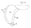
- FIG. 2a shows a representation of a section of a propeller according to the invention in the form of a single blade 3a.
- the convexly curved part 4a of the sickle-shaped blade 3a represents the entrance side and the concavely curved part 5a the exit side. It can be clearly seen that the blade was chamfered on the exit side (emphasis B). The two-sided increase the stirring resistance is significantly reduced and achieved an improved thrust / power ratio.
- FIG. 3 shows the cross section of a blade of a propeller according to the invention.
- the blade 3 is for simplicity's sake in cross section straight, that is not shown curved.
- the inlet side 4 and the outlet side 5 are sharpened according to the angles ⁇ and ⁇ . These angles may be individually in the general part of the application issued range for the cutting angle.
- the top 7 and the bottom 8 are parallel to each other and the blade 3 has over its entire width a uniform thickness d. It is also contemplated in this embodiment that the blade over its entire surface has a uniform thickness d.
- the strength is in FIG. 3 as the size d, and preferably moves within the range given in the general part of the description.
- FIG. 3a shows the cross section of a blade of the prior art.
- the angle ⁇ is about 90 ° herein.
- the edge on the exit side is not sharpened.
Description
Die vorliegende Erfindung betrifft ein axialwirkendes Rührorgan entsprechend Anspruch 1.The present invention relates to an axially acting stirring element according to
Axialwirkende Propeller sind in zahlreichen Ausführungen aus dem Stand der Technik bekannt. Als Beispiel seien die Propeller in den Rührwerken der Modelle Amamix 300 oder Amamix 400 der KSB Aktiengesellschaft genannt. Diese Modelle finden unter anderem als horizontale Tauchmotorrührwerke zum Mischen, Homogenisieren und Eindicken von kommunalen oder industriellen Abwässern und Schlämmen Verwendung. Die verwendeten Propeller sind durch die Herstellung aus gegenüber dem Förderfluid beständigen, insbesondere korrosionsbeständigen, Blechmaterialien dafür besonders geeignet. Bei Propellern, die eine konstante oder nahezu konstante Blech- oder Schaufeldicke besitzen, treten in den teilweise dickflüssigen zu rührenden Medien bei Rotation höhere Leistungsverluste an der Hinterkante auf, als bei Propellern mit profilierten Schaufeln, wobei Letztere aber wesentlich aufwändiger herzustellen sind. Somit muss mehr Energie aufgewandt werden, um den Propeller mit einer konstanten, hohen Drehzahl durch das viskose Medium rotieren zu lassen. Es ist aus dem Stand der Technik bekannt, zur Verringerung der Stirnwiderstandsverluste die Schaufeln an ihrer Eintrittsseite (der Frontseite) abzuschrägen und zu schärfen.Axial-acting propellers are known in numerous designs from the prior art. As an example, the propellers in the agitators of the models Amamix 300 or Amamix 400 KSB Aktiengesellschaft called. These models are used, inter alia, as horizontal submersible mixers for mixing, homogenizing and thickening of municipal or industrial effluents and sludges use. The propellers used are particularly suitable for the production of from the conveyor fluid resistant, in particular corrosion-resistant, sheet materials therefor. In propellers, which have a constant or nearly constant plate or blade thickness, occur in the partially viscous media to be stirred on rotation higher power losses at the trailing edge, as with propellers with profiled blades, but the latter are much more expensive to produce. Thus, more energy must be expended to rotate the propeller at a constant, high speed through the viscous medium. It is known in the art to skew and sharpen the blades on their entry side (front) to reduce endurance losses.
Ausgehend von dieser und ähnlichen Konstruktionen ist es Ziel der vorliegenden Erfindung, den Rotationswiderstand eines Propellers weiter zu verringern. Es kann daraus auch eine spürbare Einsparung der für den Rührvorgang benötigten Energie erzielt werden. Ein weiteres Ziel der Erfindung ist es also, bei Einsatz eines erfindungsgemäßen Rührorganes ein verbessertes Rührergebnis bei gleichbleibendem Energieaufwand, ein gleichbleibendes Rührergebnis bei geringerem Energieaufwand oder ein verbessertes Rührergebnis bei geringerem Energieaufwand zu erreichen.Based on this and similar constructions, the object of the present invention is to further reduce the rotational resistance of a propeller. It can also be achieved a significant saving of the energy required for the stirring process. A further object of the invention is therefore to achieve an improved stirring result with constant expenditure of energy, a constant stirring result with less expenditure of energy or an improved stirring result with less expenditure of energy when using a stirring element according to the invention.
Diese Ziele werden erfindungsgemäß durch Einsatz eines axialen Rührorganes nach Anspruch 1 erreicht. Ein axialwirkendes Rührorgan, vorzugsweise Propeller, mit radial um eine Achse angeordneten Schaufeln soll demnach nur ein Teil, vorzugsweise die äußere Hälfte, besonders vorzugsweise die äußeren zwei Drittel der Kante an der Austrittsseite die zugeschärfte Kante aufweist.These objects are achieved according to the invention by use of an axial stirring element according to
Als "axiale" Rührorgane werden hier solche Rührorgane verstanden, an welchen die Schaufeln radial und zumeist schräg angestellt um eine Drehachse angeordnet sind. Die Primärströmung des gerührten Mediums bei Betrieb eines solchen axialen Rührorganes ist stets axial gerichtet. Als Eintrittsseite oder Frontseite ist diejenige Kante der Schaufel zu verstehen, welche beim Betrieb des Rührorganes in der vorgesehenen Rotationsrichtung vorauseilt. Als Austrittsseite oder Heckseite ist diejenige Kante der Schaufel zu verstehen, welche beim Betrieb des Rührorganes in der vorgesehenen Rotationsrichtung nacheilt.As "axial" stirring means are understood here Rührorgane on which the blades are arranged radially and mostly obliquely adjusted about an axis of rotation. The primary flow of the stirred medium during operation of such an axial stirring element is always directed axially. The entry side or front side is to be understood as that edge of the blade which leads in the intended direction of rotation during operation of the stirring element. The outlet side or rear side is that edge of the blade which lags in the intended direction of rotation during operation of the stirring element.
Bevorzugte Ausgestaltungen der Erfindung ergeben sich aus den sich an den Hauptanspruch anschließenden Unteransprüchen.Preferred embodiments of the invention will become apparent from the subsequent claims to the main claim.
In einer ersten bevorzugten Ausführungsform der Erfindung sind eine oder mehrere Schaufeln auch an der Eintrittsseite zugeschärft. Durch einen optimierten Schliff kann das Schub/Leistungsverhältnis verbessert werden. In einer weiteren Ausführungsform mit einer entsprechenden Zuschärfung an der Front- und der Rückseite können die Verbesserungen, die aus einer Zuschärfung nur an der Front- oder der Rückseite resultieren, deutlich übertroffen werden.In a first preferred embodiment of the invention, one or more blades are also sharpened at the entrance side. Through optimized grinding, the thrust / power ratio can be improved. In a further embodiment with a corresponding reinforcement on the front and the back, the improvements that result from a reinforcement only at the front or the back, can be significantly exceeded.
Ein erfindungsgemäßes Rührorgarn besitzt mindestens eine Schaufel mit den vorgenannten Eigenschaften. Bevorzugt sind mehrere, die Hälfte oder alle Schaufeln des erfindungsgemäßen Rührorganes an der Ein- und/oder Austrittsseite zugeschärft.An agitator yarn according to the invention has at least one blade with the aforementioned properties. Preferably, several, half or all of the blades of the stirring element according to the invention are sharpened on the inlet and / or outlet side.
Es wurde festgestellt, dass bei der Rotation eines solchen Rührorganes durch ein viskoses Medium nicht nur an der Eintrittsseite sondern auch an der Austrittsseite (der Heckseite) der Schaufeln durch die mangelnde Stromlinienförmigkeit Umströmungen und Turbulenzen auftreten, welche Rotationswiderstände und damit Leistungsverluste hervorrufen. Die Umströmungen an der Austrittskante stellen einen Verlust dar, dessen Größe im Stand der Technik bisher noch nicht berücksichtigt wurde. Durch die Zuschärfung, d.h. Abschrägung wurde eine Verringerung der Leistungsverluste und somit ein verbessertes Schub/Leistungsverhältnis bei der Rotation vor allem ansonsten einfach aufgebauter axialer Blechpropeller erreicht.It has been found that during the rotation of such a stirring element by a viscous medium not only at the inlet side but also at the outlet side (the rear side) of the blades by the lack of streamline flow and turbulence occur, which cause rotational resistance and thus power losses. The flow around the trailing edge represents a loss whose size has not yet been considered in the prior art. By the accretion, i. Beveling has been achieved a reduction of power losses and thus an improved thrust / power ratio in the rotation of all otherwise simply constructed axial metal propeller.
In einer weiteren Ausführungsform der Erfindung, in der eine oder mehrere Schaufeln an Front- und/oder Heckseite zugeschärft sind, besitzt die Zuschärfung an Ein- und/oder Austrittsseite individuell einen Anstellwinkel von zwischen etwa 5° bis etwa 30°, bevorzugt zwischen etwa 10° bis etwa 15°. Dieser Anstellwinkel kann beim Vorhandensein mehrerer an der Austrittsseite zugeschärfter Schaufeln über alle Schaufeln hinweg einen konstanten Winkel haben. Dasselbe gilt, wenn mehrere an der Eintrittsseite zugeschärfte Schaufeln vorhanden sind.In a further embodiment of the invention, in which one or more blades are sharpened on the front and / or rear side, the increase on the inlet and / or outlet side individually has an angle of attack of between about 5 ° to about 30 °, preferably between about 10 ° to about 15 °. This angle of attack may have a constant angle across all blades when there are multiple blades that are sharpened on the exit side. The same applies if there are several blades which have been sharpened on the inlet side.
Weiters kann in einer Ausführungsform vorgesehen sein, dass bei zugeschliffenen Front- und/oder Heckseiten der Schliff an der Saugseite der Schaufeln angebracht ist. Unter der Oberseite der Schaufeln ist diejenige Seite entlang der Drehachse zu verstehen, von welcher aus bei Rotation des Propellers in der vorgesehenen Drehrichtung das durchrührte Medium das Rührorgan durchfließt, d.h. die stromaufwärts liegende Seite der Schaufeln. Ein solcher Schliff kann sich wiederum positiv auf die Automatisierbarkeit und Kosten der Konstruktion auswirken.Furthermore, it may be provided in one embodiment that, when the front and / or rear sides are ground, the ground joint is attached to the suction side of the blades. Under the top of the blades is to be understood that side along the axis of rotation, from which, upon rotation of the propeller in the intended direction of rotation, the agitated medium flows through the agitator, i. the upstream side of the blades. Such a cut can in turn have a positive effect on the automation and cost of the construction.
Nicht die gesamte Kante ist zugeschärft, sondern nur ein Bereich. Dies kann bevorzugt der äußere, d.h. der weiter von der Drehachse entfernte Bereich sein, da hier die Absolutgeschwindigkeit der Kanten durch das Medium bei gleicher Drehzahl höher ist als im inneren Bereich. So werden die Schaufeln in einer Ausführungsform nur in den äußeren zwei Dritteln oder nur der äußeren Hälfte behandelt. Diese Größen sind für den Fachmann als Richtwerte zu verstehen und hängen weitgehend von der Größe und Form des Propellers und dem Einsatzbereich und der Betriebsdrehzahl ab.Not the entire edge is sharpened, but only one area. This may preferably be the outer, i. the area further away from the axis of rotation, since here the absolute speed of the edges through the medium at the same speed is higher than in the inner area. Thus, in one embodiment, the blades are treated only in the outer two-thirds or only the outer half. These quantities are to be understood by those skilled in the art as guidelines and depend largely on the size and shape of the propeller and the application and operating speed.
Versuche haben weiter gezeigt, dass vor allem bei kleineren Propellern, die durch relativ kurze Schaufellängen gekennzeichnet sind und deren Drehzahl gegebenenfalls relativ hoch sein kann, d.h. im Bereich von über 600 U/min, über 800 U/min, über 1000 U/min oder sogar über 2000 U/min, an der Austrittsseite nicht mehr zu vernachlässigende Verluste entstehen können.Experiments have further shown that especially with smaller propellers, which are characterized by relatively short blade lengths and their speed may be relatively high, i. in the range of over 600 rev / min, over 800 rev / min, over 1000 rev / min or even over 2000 rev / min, at the outlet side no longer negligible losses may occur.
Daher wird ein solches Rührorgan in einer Ausführungsform mit einem Gesamtdurchmesser von zwischen etwa 20 cm und etwa 1 m, bevorzugt zwischen etwa 30 cm und etwa 60 cm und besonders bevorzugt zwischen etwa 30 cm und etwa 40 cm eingesetzt. In einer anderen Ausführungsform beträgt der Gesamtdurchmesser zwischen etwa 40 cm und etwa 80 cm. Auch Rührorgandurchmesser von größer als 1 m sind zum Einsatz in entsprechenden Rührwerken jedoch geeignet und sollen einen spürbaren Gewinn im Schub/Leistungsverhältnis begründen.Thus, in one embodiment, such an agitator is used with an overall diameter of between about 20 cm and about 1 m, preferably between about 30 cm and about 60 cm, and more preferably between about 30 cm and about 40 cm. In another embodiment, the overall diameter is between about 40 cm and about 80 cm. However, agitator orbital diameters greater than 1 m are also suitable for use in corresponding agitators and should justify a noticeable gain in the thrust / power ratio.
Eine oder mehrere Schaufeln sind aus Blech gefertigt. Eine derartige Konstruktion aus Blech hat in der Praxis den Vorteil einer vergleichsweise billigen Produktion und einer hohen Stabilität. Unter dem Begriff Blech ist eine flache oder nahezu flache Platte aus Metall zu verstehen. Viele Metalle und vor allem Legierungen eignen sich als Grundstoffe für die vorliegende Anwendung, in einer Ausführungsform sind jedoch gegenüber den Förderfluiden beständige Stahlbleche und Aluminiumbleche besonders hervorzuheben.One or more blades are made of sheet metal. Such a sheet metal construction has in practice the advantage of a comparatively cheap production and high stability. The term sheet metal is to be understood as meaning a flat or nearly flat sheet of metal. Many metals, and especially alloys, are useful as base materials for the present application, however, in one embodiment, resistant steel sheets and aluminum sheets are particularly notable over the production fluids.
In einer weiteren Ausführungsform der Erfindung hat eine oder mehrere Schaufeln außerhalb der zugeschärften Stellen eine konstante Dicke. Dies ist ebenfalls in der Produktion preislich vorteilhaft, begründet ein moderates Gewicht der Propellerrührer und hat den Vorteil eines geringen Drehwiderstandes. Bleche besitzen normalerweise über deren Fläche eine konstante Dicke. In einer weiteren Ausführungsform der Erfindung sind die Schaufeln, bzw. das den Schaufeln zugrunde liegende Material, bevorzugt Blech, zwischen 3 und 15 mm, bevorzugt zwischen 3 und 8 mm stark. Auch diese Werte variieren natürlich je nach Anwendung und Rührorgandurchmesser.In another embodiment of the invention, one or more blades outside the sharpened locations has a constant thickness. This is also advantageous in terms of price, justifies a moderate weight of the propeller stirrer and has the advantage of a low rotational resistance. Sheets usually have a constant thickness over their surface. In a further embodiment of the invention, the blades or the material underlying the blades, preferably sheet metal, are between 3 and 15 mm, preferably between 3 and 8 mm thick. These values also vary, of course, depending on the application and Rührorgandurchmesser.
In einer bevorzugten Ausführungsform sind eine oder mehrere Schaufeln gewölbt. Diese Konstruktion ist bei einem Propellerrührer vorteilhaft, um eine möglichst axiale Hauptachse bei der Flussrichtung des gerührten Mediums zu begründen. Bevorzugt besitzt die Krümmung der Wölbung an jeder Stelle der Schaufel ein einheitliches Vorzeichen oder ist 0. In einer anderen Ausführungsform ist die Krümmung dermaßen gestaltet, dass die Schaufeln an der Stelle der Befestigung an der Welle in eine in Bezug auf die Rotationsrichtung angewinkelte Ausrichtung und an den äußeren Enden eine Stellung entlang der Rotationsrichtung aufweisen.In a preferred embodiment, one or more blades are arched. This construction is advantageous in the case of a propeller stirrer in order to justify an axial axis which is as large as possible in the direction of flow of the stirred medium. Preferably, the curvature of the curvature at each point of the blade has a uniform sign or is 0. In another embodiment, the curvature is such that the blades, at the location of attachment to the shaft, are angled in relation to the direction of rotation and at the outer ends have a position along the direction of rotation.
Es ist daher konstruktiv vorteilhaft, dass das für die Konstruktion des Propellers verwendet Blech zur Form einer Schaufel gebogen ist und an eine Propellernabe geschweißt ist.It is therefore constructively advantageous that the sheet used for the construction of the propeller is bent to the shape of a blade and welded to a propeller hub.
Eine oder mehrere Schaufeln sind sichelförmig. Diese sichelförmige Form kann sich sowohl aus der Form des ungewölbten Materials, bevorzugt des Blechs ergeben, oder bei der Draufsicht auf die Schaufeln entlang der Drehachse. An der Außenseite laufen die Schaufeln in einer bevorzugten Ausführungsform nicht spitz zusammen, sondern sind abgerundet bzw. schräg oder tangential abgeschnitten. Eine solche Konstruktion hat eine hohe Stabilität der Schaufeln bis in deren Endbereich und eine geringere Turbulenzenbildung zur Folge.One or more blades are sickle-shaped. This crescent-shaped shape can be formed both from the shape of the non-arched material, preferably the sheet yield, or in the plan view of the blades along the axis of rotation. In a preferred embodiment, the blades do not converge on the outside in a pointed manner, but are rounded off or obliquely or tangentially cut off. Such a design results in a high stability of the blades into their end region and less turbulence formation.
Mindestens zwei Schaufeln sind in ihrer Größe, ihrem Abstand und/oder ihrer Form dermaßen gestaltet, dass sich bei einer Draufsicht in Richtung der Drehachse einzelne Schaufeln überlagern. Bevorzugt haben alle Schaufeln den gleichen Abstand, zumindest aber ein regelmäßiges Abstandsmuster zueinander. Die bevorzugte Zahl der Schaufeln eines erfindungsgemäßen Propellers liegt im Regelfall zwischen 2 und etwa 10 Schaufeln, bevorzugt zwischen 2 und 5 Schaufeln und besonders bevorzugt bei genau 3 Schaufeln. Über ihre oben über den Durchmesser näher bestimmte Länge (etwa D/2) besitzen die Schaufeln eine Breite von zwischen etwa 5 cm und etwa 30 cm, bevorzugt zwischen etwa 10 cm und etwa 25 cm. Diese Größe kann sich sowohl auf die Breite bevorzugt des Blechs vor der Krümmung beziehen, als auch auf die Breite des Propellers bei der Draufsicht aus axialer Richtung.At least two blades are designed such that their size, their distance and / or their shape that superimpose individual blades in a plan view in the direction of the axis of rotation. Preferably, all blades have the same distance, but at least a regular distance pattern to each other. The preferred number of blades of a propeller according to the invention is generally between 2 and about 10 blades, preferably between 2 and 5 blades and more preferably with exactly 3 blades. The blades have a width of between about 5 cm and about 30 cm, preferably between about 10 cm and about 25 cm, over their length (about D / 2), which is determined closer above the diameter. This size can relate both to the width of the sheet before the bend and to the width of the propeller when viewed from the axial direction.
Solche Propeller können zentrisch oder auch exzentrisch in ein zu mischendes oder zu rührendes Medium eingebracht werden. Mehrere derartige Propeller innerhalb eines Mediums sind ebenfalls denkbar. Der Propeller kann entlang einer Achse senkrecht von oben oder von unten in den Zielbereich eingebracht werden oder auch seitlich, schräg oder angewinkelt.Such propellers can be introduced centrically or eccentrically into a medium to be mixed or stirred. Several such propellers within a medium are also conceivable. The propeller can be introduced along an axis perpendicular from above or from below into the target area or laterally, obliquely or angled.
Ein weiteres Augenmerk der Erfindung liegt auf der Verwendung eines soeben beschriebenen Rührorganes. In einer bevorzugten Verwendung findet ein solches Rührorgan Anwendung in einem Rührwerk zum Rühren und/oder Mischen. Bevorzugt ist die Verwendung in einem Mixer oder einem Tauchmotorrührwerk, besonders bevorzugt zum Mischen, Homogenisieren und Eindicken von bevorzugt kommunalen und/oder industriellen Abwässern oder Schlämmen vorgesehen. In einer Ausführungsform wird der Propeller dabei zwischen etwa 100 und etwa 1500 Umdrehungen pro Minute erfahren, bevorzugt zwischen etwa 500 und etwa 1000 Umdrehungen pro Minute. Eine beispielhafte maximale Antriebsleistung für die industrielle Verwendung soll etwa 5 kW sein. Bevorzugt wird ein solcher Propeller mit einem Elektromotor betrieben.A further aspect of the invention is the use of a stirring element just described. In a preferred use, such a stirring element is used in an agitator for stirring and / or mixing. The use is preferably provided in a mixer or a submersible mixer, particularly preferably for mixing, homogenizing and thickening of preferably municipal and / or industrial wastewaters or sludges. In one embodiment, the propeller is between about 100 and about 1500 Experiments revolutions per minute, preferably between about 500 and about 1000 revolutions per minute. An exemplary maximum drive power for industrial use should be about 5 kW. Such a propeller is preferably operated with an electric motor.
Somit umfasst die Erfindung auch solche Rührwerke, die sich zur soeben genannten Anwendung eignen und ein erfindungsgemäßes Rührorgan aufweisen.Thus, the invention also includes such agitators, which are suitable for the just mentioned application and have an inventive stirring element.
Merkmale, Einzelheiten und Vorteile der Erfindung werden nachfolgend anhand in der Zeichnung dargestellter Ausführungsbeispiele erläutert. Es zeigen:
- Figur 1:
- eine Schrägansicht eines erfindungsgemäßen Rührorganes,
- Figur 1a:
- eine Schrägansicht eines Rührorganes aus dem Stand der Technik,
- Figur 2:
- eine Abbildung eines erfindungsgemäßen Propellers,
- Figur 2a:
- eine Schaufel eines erfindungsgemäßen Propellers,
- Figur 3:
- einen Querschnitt einer erfindungsgemäßen Schaufel, und
Figur 3a:- einen Querschnitt einer Schaufel aus dem Stand der Technik.
- FIG. 1:
- an oblique view of a stirring element according to the invention,
- FIG. 1a
- an oblique view of a stirrer of the prior art,
- FIG. 2:
- an illustration of a propeller according to the invention,
- FIG. 2a:
- a blade of a propeller according to the invention,
- FIG. 3:
- a cross section of a blade according to the invention, and
- FIG. 3a:
- a cross section of a blade of the prior art.
Dies steht im Gegensatz zu
Im Gegensatz dazu zeigt
Claims (9)
- Axially operating stirring element, preferably a propeller (1) manufactured from sheet metal and having propeller blades (3) arranged radially about an axis (A), one or more propeller blades (3) being formed from sheet metal, the sheet metal being bent into the form of the blade and being welded to a propeller hub (2), one or more blades being formed in a sickle-shaped manner and preferably being rounded or obliquely or tangentially cut off at the outer ends (6), at least two individual blades being superposed one on the other in a top view in the direction of the axis, the said stirring element having at least one propeller blade which possesses a chamfered edge on the exit side (5),
characterized
in that only part, preferably the outer half, especially preferably the outer two thirds, of the edge has the chamfered edge on the exit side. - Axially operating stirring element, preferably propeller, according to Claim 1, the at least one propeller blade also possessing a chamfered edge on the entry side (4).
- Axially operating stirring element, preferably propeller, according to one of the preceding claims, a plurality of and preferably all of the propeller blades of the stirring element having chamfered edges on the entry side and/or the exit side.
- Axially operating stirring element, preferably propeller, according to one of the preceding claims, the chamfer on the entry side and/or exit side individually having a pitch angle of between 5° and 30°, preferably of between 10° and 15°.
- Axially operating stirring element, preferably propeller, according to either one of Claims 3 and 4, the chamfer having on the entry side and/or exit side a constant angle over all the propeller blades.
- Axially operating stirring element, preferably propeller, according to one of the preceding claims, one or more blades being manufactured from sheet metal.
- Axially operating stirring element, preferably propeller, according to one of the preceding claims, one or more blades having a constant thickness outside the chamfered locations.
- Agitator for stirring and/or mixing, preferably mixer or submersible motor-driven agitator with a stirring element according to one of the preceding claims.
- Agitator according to Claim 8 for the mixing, homogenizing and thickening of preferably municipal and/or industrial sewages or sludges.
Priority Applications (1)
| Application Number | Priority Date | Filing Date | Title |
|---|---|---|---|
| PL10755165T PL2480321T3 (en) | 2009-09-24 | 2010-09-20 | Axially operating stirring element |
Applications Claiming Priority (3)
| Application Number | Priority Date | Filing Date | Title |
|---|---|---|---|
| DE102009042843 | 2009-09-24 | ||
| DE102010044423A DE102010044423A1 (en) | 2009-09-24 | 2010-09-04 | Axial-action stirrer, preferably a propeller made of sheet metal |
| PCT/EP2010/063777 WO2011036113A2 (en) | 2009-09-24 | 2010-09-20 | Axially operating stirring element, preferably a propeller manufactured from sheet metal |
Publications (2)
| Publication Number | Publication Date |
|---|---|
| EP2480321A2 EP2480321A2 (en) | 2012-08-01 |
| EP2480321B1 true EP2480321B1 (en) | 2015-04-15 |
Family
ID=43705865
Family Applications (1)
| Application Number | Title | Priority Date | Filing Date |
|---|---|---|---|
| EP10755165.7A Active EP2480321B1 (en) | 2009-09-24 | 2010-09-20 | Axially operating stirring element |
Country Status (12)
| Country | Link |
|---|---|
| US (1) | US20120188843A1 (en) |
| EP (1) | EP2480321B1 (en) |
| CN (1) | CN102510773A (en) |
| AU (1) | AU2010299998B2 (en) |
| BR (1) | BR112012006425A2 (en) |
| CA (1) | CA2775123C (en) |
| DE (1) | DE102010044423A1 (en) |
| DK (1) | DK2480321T3 (en) |
| ES (1) | ES2541599T3 (en) |
| PL (1) | PL2480321T3 (en) |
| RU (1) | RU2559501C2 (en) |
| WO (1) | WO2011036113A2 (en) |
Families Citing this family (2)
| Publication number | Priority date | Publication date | Assignee | Title |
|---|---|---|---|---|
| US9962665B2 (en) | 2012-06-20 | 2018-05-08 | Philadelphia Mixing Solutions, Ltd. | High efficiency, non-ragging, formed axial impeller |
| US11596907B1 (en) | 2019-06-14 | 2023-03-07 | Aeration Industries International, Llc | Apparatus for treating fluids having improved aeration efficiency and operational durability |
Family Cites Families (19)
| Publication number | Priority date | Publication date | Assignee | Title |
|---|---|---|---|---|
| US2293183A (en) * | 1939-04-03 | 1942-08-18 | American Well Works | Mixing turbine |
| US2336303A (en) * | 1941-08-04 | 1943-12-07 | Frank H Schubert | Method of making fans |
| US2799919A (en) * | 1951-11-01 | 1957-07-23 | Gen Motors Corp | Sheet metal blade and manufacture |
| GB786727A (en) * | 1954-05-11 | 1957-11-27 | Edward Archibald Stalker | Method and apparatus for making hollow blades for compressors and gas turbines |
| US3184833A (en) * | 1956-02-01 | 1965-05-25 | Borg Warner | Method of making vanes for hydraulic couplings |
| US4240990A (en) * | 1979-04-10 | 1980-12-23 | Aeration Industries, Inc. | Aeration propeller and apparatus |
| SU1197717A1 (en) * | 1984-01-13 | 1985-12-15 | Государственный научно-исследовательский и проектный институт по обогащению руд цветных металлов "Казмеханобр" | Powder dispenser |
| GB8617569D0 (en) * | 1986-07-18 | 1986-08-28 | Davidson J F | Impellers |
| US5211924A (en) * | 1988-02-29 | 1993-05-18 | Amoco Corporation | Method and apparatus for increasing conversion efficiency and reducing power costs for oxidation of an aromatic alkyl to an aromatic carboxylic acid |
| US5052892A (en) * | 1990-01-29 | 1991-10-01 | Chemineer, Inc. | High efficiency mixer impeller |
| US5297938A (en) * | 1990-03-26 | 1994-03-29 | Philadelphia Mixers Corporation | Hydrofoil impeller |
| US5100240A (en) * | 1990-05-11 | 1992-03-31 | Alterio Joseph C D | High-speed continuous mixer for solids and liquids |
| SU1761244A1 (en) * | 1990-07-02 | 1992-09-15 | Днепропетровский инженерно-строительный институт | Device for producing foamy aerosol |
| US5158434A (en) * | 1990-07-26 | 1992-10-27 | General Signal Corporation | Mixing impellers and impeller systems for mixing and blending liquids and liquid suspensions having a wide range of viscosities |
| DE4226498A1 (en) * | 1992-08-11 | 1994-02-17 | Klein Schanzlin & Becker Ag | Agitator propeller |
| US5344235A (en) * | 1993-01-21 | 1994-09-06 | General Signal Corp. | Erosion resistant mixing impeller |
| US6550703B2 (en) * | 2001-03-29 | 2003-04-22 | Hamilton Beach/Proctor-Silex, Inc. | Blender cutter |
| US6866414B2 (en) * | 2001-05-22 | 2005-03-15 | Jv Northwest, Inc. | Sanitary mixing assembly for vessels and tanks |
| CN201316604Y (en) * | 2008-12-02 | 2009-09-30 | 北京矿冶研究总院 | Impeller type stirring device |
-
2010
- 2010-09-04 DE DE102010044423A patent/DE102010044423A1/en not_active Withdrawn
- 2010-09-20 BR BR112012006425-8A patent/BR112012006425A2/en not_active Application Discontinuation
- 2010-09-20 DK DK10755165.7T patent/DK2480321T3/en active
- 2010-09-20 WO PCT/EP2010/063777 patent/WO2011036113A2/en active Application Filing
- 2010-09-20 EP EP10755165.7A patent/EP2480321B1/en active Active
- 2010-09-20 ES ES10755165.7T patent/ES2541599T3/en active Active
- 2010-09-20 CN CN2010800426413A patent/CN102510773A/en active Pending
- 2010-09-20 AU AU2010299998A patent/AU2010299998B2/en not_active Ceased
- 2010-09-20 PL PL10755165T patent/PL2480321T3/en unknown
- 2010-09-20 CA CA2775123A patent/CA2775123C/en active Active
- 2010-09-20 RU RU2012114482/05A patent/RU2559501C2/en not_active Application Discontinuation
-
2012
- 2012-03-23 US US13/428,217 patent/US20120188843A1/en not_active Abandoned
Also Published As
| Publication number | Publication date |
|---|---|
| CA2775123C (en) | 2017-10-24 |
| DE102010044423A1 (en) | 2011-04-07 |
| PL2480321T3 (en) | 2015-10-30 |
| DK2480321T3 (en) | 2015-06-29 |
| US20120188843A1 (en) | 2012-07-26 |
| WO2011036113A3 (en) | 2011-05-19 |
| CN102510773A (en) | 2012-06-20 |
| AU2010299998A1 (en) | 2012-04-12 |
| BR112012006425A2 (en) | 2020-11-03 |
| CA2775123A1 (en) | 2011-03-31 |
| EP2480321A2 (en) | 2012-08-01 |
| RU2559501C2 (en) | 2015-08-10 |
| WO2011036113A2 (en) | 2011-03-31 |
| ES2541599T3 (en) | 2015-07-22 |
| RU2012114482A (en) | 2013-10-27 |
| AU2010299998B2 (en) | 2013-11-07 |
Similar Documents
| Publication | Publication Date | Title |
|---|---|---|
| EP0112932B1 (en) | Radial ventilator with backwards-curved profiled blades | |
| DE2624991C2 (en) | Impeller | |
| EP3171970B1 (en) | Stirring member apparatus | |
| EP2125179B1 (en) | Horizontal agitator and method for producing a flow in a clearing basin using the horizontal agitator | |
| EP1475145B1 (en) | Impeller | |
| DE2421237C2 (en) | Submersible pump | |
| EP3066188B1 (en) | Agitating device for a fermenter of a biogas plant and method for producing an agitating device | |
| EP2228541B1 (en) | Rotor for a rotary pump | |
| EP2125180B1 (en) | Horizontal agitator and device for producing a flow in a clearing basin using the horizontal agitator | |
| EP2150330B1 (en) | Stirring member for stirring abrasive media | |
| DE4401596A1 (en) | Stirrer | |
| EP2480321B1 (en) | Axially operating stirring element | |
| CH645954A5 (en) | IMPELLER FOR DRIVING A FLUID AND IMPELLER TO BE DRIVED BY A FLUID. | |
| EP2321398B9 (en) | Mash tun for producing beer and stirrer for a mash tun | |
| AT16295U1 (en) | Pulper rotor and pulper | |
| EP1473078B1 (en) | Submersible motorised stirrer for biogas installations | |
| DE102007008131A1 (en) | Horizontal agitator, to generate a flow in a sewage settling basin, has an immersed motor with a propeller fitted with blades of elastic distortion material | |
| DE202015004925U1 (en) | propeller | |
| WO2012038054A1 (en) | Stirring blade and stirring device | |
| DE60311165T2 (en) | Centrifugal pump for low flow rates with improved suction height | |
| DE2538156C2 (en) | Aeration agitator | |
| DE4110540A1 (en) | Wind-operated power generator - has profiled axial blades in ring around rotor with convex-curved surfaces leading | |
| DE19720120C2 (en) | Stirrer | |
| AT412495B (en) | WHEEL OF A HYDRAULIC MACHINE | |
| DE1528637C (en) | Thick matter centrifugal pump |
Legal Events
| Date | Code | Title | Description |
|---|---|---|---|
| PUAI | Public reference made under article 153(3) epc to a published international application that has entered the european phase |
Free format text: ORIGINAL CODE: 0009012 |
|
| 17P | Request for examination filed |
Effective date: 20120305 |
|
| AK | Designated contracting states |
Kind code of ref document: A2 Designated state(s): AL AT BE BG CH CY CZ DE DK EE ES FI FR GB GR HR HU IE IS IT LI LT LU LV MC MK MT NL NO PL PT RO SE SI SK SM TR |
|
| DAX | Request for extension of the european patent (deleted) | ||
| 17Q | First examination report despatched |
Effective date: 20130207 |
|
| GRAP | Despatch of communication of intention to grant a patent |
Free format text: ORIGINAL CODE: EPIDOSNIGR1 |
|
| INTG | Intention to grant announced |
Effective date: 20141113 |
|
| GRAS | Grant fee paid |
Free format text: ORIGINAL CODE: EPIDOSNIGR3 |
|
| GRAA | (expected) grant |
Free format text: ORIGINAL CODE: 0009210 |
|
| AK | Designated contracting states |
Kind code of ref document: B1 Designated state(s): AL AT BE BG CH CY CZ DE DK EE ES FI FR GB GR HR HU IE IS IT LI LT LU LV MC MK MT NL NO PL PT RO SE SI SK SM TR |
|
| REG | Reference to a national code |
Ref country code: GB Ref legal event code: FG4D Free format text: NOT ENGLISH Ref country code: CH Ref legal event code: EP |
|
| REG | Reference to a national code |
Ref country code: IE Ref legal event code: FG4D Free format text: LANGUAGE OF EP DOCUMENT: GERMAN |
|
| REG | Reference to a national code |
Ref country code: AT Ref legal event code: REF Ref document number: 721640 Country of ref document: AT Kind code of ref document: T Effective date: 20150515 |
|
| REG | Reference to a national code |
Ref country code: DE Ref legal event code: R096 Ref document number: 502010009355 Country of ref document: DE Effective date: 20150528 |
|
| REG | Reference to a national code |
Ref country code: DK Ref legal event code: T3 Effective date: 20150625 |
|
| REG | Reference to a national code |
Ref country code: ES Ref legal event code: FG2A Ref document number: 2541599 Country of ref document: ES Kind code of ref document: T3 Effective date: 20150722 |
|
| REG | Reference to a national code |
Ref country code: SE Ref legal event code: TRGR |
|
| REG | Reference to a national code |
Ref country code: FR Ref legal event code: PLFP Year of fee payment: 6 |
|
| REG | Reference to a national code |
Ref country code: LT Ref legal event code: MG4D |
|
| PG25 | Lapsed in a contracting state [announced via postgrant information from national office to epo] |
Ref country code: LT Free format text: LAPSE BECAUSE OF FAILURE TO SUBMIT A TRANSLATION OF THE DESCRIPTION OR TO PAY THE FEE WITHIN THE PRESCRIBED TIME-LIMIT Effective date: 20150415 Ref country code: HR Free format text: LAPSE BECAUSE OF FAILURE TO SUBMIT A TRANSLATION OF THE DESCRIPTION OR TO PAY THE FEE WITHIN THE PRESCRIBED TIME-LIMIT Effective date: 20150415 Ref country code: PT Free format text: LAPSE BECAUSE OF FAILURE TO SUBMIT A TRANSLATION OF THE DESCRIPTION OR TO PAY THE FEE WITHIN THE PRESCRIBED TIME-LIMIT Effective date: 20150817 Ref country code: NO Free format text: LAPSE BECAUSE OF FAILURE TO SUBMIT A TRANSLATION OF THE DESCRIPTION OR TO PAY THE FEE WITHIN THE PRESCRIBED TIME-LIMIT Effective date: 20150715 |
|
| REG | Reference to a national code |
Ref country code: PL Ref legal event code: T3 |
|
| PG25 | Lapsed in a contracting state [announced via postgrant information from national office to epo] |
Ref country code: IS Free format text: LAPSE BECAUSE OF FAILURE TO SUBMIT A TRANSLATION OF THE DESCRIPTION OR TO PAY THE FEE WITHIN THE PRESCRIBED TIME-LIMIT Effective date: 20150815 Ref country code: GR Free format text: LAPSE BECAUSE OF FAILURE TO SUBMIT A TRANSLATION OF THE DESCRIPTION OR TO PAY THE FEE WITHIN THE PRESCRIBED TIME-LIMIT Effective date: 20150716 Ref country code: LV Free format text: LAPSE BECAUSE OF FAILURE TO SUBMIT A TRANSLATION OF THE DESCRIPTION OR TO PAY THE FEE WITHIN THE PRESCRIBED TIME-LIMIT Effective date: 20150415 |
|
| REG | Reference to a national code |
Ref country code: DE Ref legal event code: R026 Ref document number: 502010009355 Country of ref document: DE |
|
| PLBI | Opposition filed |
Free format text: ORIGINAL CODE: 0009260 |
|
| PG25 | Lapsed in a contracting state [announced via postgrant information from national office to epo] |
Ref country code: EE Free format text: LAPSE BECAUSE OF FAILURE TO SUBMIT A TRANSLATION OF THE DESCRIPTION OR TO PAY THE FEE WITHIN THE PRESCRIBED TIME-LIMIT Effective date: 20150415 |
|
| PLAX | Notice of opposition and request to file observation + time limit sent |
Free format text: ORIGINAL CODE: EPIDOSNOBS2 |
|
| 26 | Opposition filed |
Opponent name: XYLEM IP MANAGEMENT S.A.R.L. Effective date: 20160115 |
|
| PG25 | Lapsed in a contracting state [announced via postgrant information from national office to epo] |
Ref country code: RO Free format text: LAPSE BECAUSE OF NON-PAYMENT OF DUE FEES Effective date: 20150415 Ref country code: SK Free format text: LAPSE BECAUSE OF FAILURE TO SUBMIT A TRANSLATION OF THE DESCRIPTION OR TO PAY THE FEE WITHIN THE PRESCRIBED TIME-LIMIT Effective date: 20150415 |
|
| PG25 | Lapsed in a contracting state [announced via postgrant information from national office to epo] |
Ref country code: LU Free format text: LAPSE BECAUSE OF FAILURE TO SUBMIT A TRANSLATION OF THE DESCRIPTION OR TO PAY THE FEE WITHIN THE PRESCRIBED TIME-LIMIT Effective date: 20150920 Ref country code: MC Free format text: LAPSE BECAUSE OF FAILURE TO SUBMIT A TRANSLATION OF THE DESCRIPTION OR TO PAY THE FEE WITHIN THE PRESCRIBED TIME-LIMIT Effective date: 20150415 |
|
| REG | Reference to a national code |
Ref country code: CH Ref legal event code: PL |
|
| PG25 | Lapsed in a contracting state [announced via postgrant information from national office to epo] |
Ref country code: SI Free format text: LAPSE BECAUSE OF FAILURE TO SUBMIT A TRANSLATION OF THE DESCRIPTION OR TO PAY THE FEE WITHIN THE PRESCRIBED TIME-LIMIT Effective date: 20150415 |
|
| PLAF | Information modified related to communication of a notice of opposition and request to file observations + time limit |
Free format text: ORIGINAL CODE: EPIDOSCOBS2 |
|
| REG | Reference to a national code |
Ref country code: IE Ref legal event code: MM4A |
|
| PLBP | Opposition withdrawn |
Free format text: ORIGINAL CODE: 0009264 |
|
| PG25 | Lapsed in a contracting state [announced via postgrant information from national office to epo] |
Ref country code: CH Free format text: LAPSE BECAUSE OF NON-PAYMENT OF DUE FEES Effective date: 20150930 Ref country code: IE Free format text: LAPSE BECAUSE OF NON-PAYMENT OF DUE FEES Effective date: 20150920 Ref country code: LI Free format text: LAPSE BECAUSE OF NON-PAYMENT OF DUE FEES Effective date: 20150930 |
|
| PLAF | Information modified related to communication of a notice of opposition and request to file observations + time limit |
Free format text: ORIGINAL CODE: EPIDOSCOBS2 |
|
| REG | Reference to a national code |
Ref country code: FR Ref legal event code: PLFP Year of fee payment: 7 |
|
| PLBB | Reply of patent proprietor to notice(s) of opposition received |
Free format text: ORIGINAL CODE: EPIDOSNOBS3 |
|
| PG25 | Lapsed in a contracting state [announced via postgrant information from national office to epo] |
Ref country code: MT Free format text: LAPSE BECAUSE OF FAILURE TO SUBMIT A TRANSLATION OF THE DESCRIPTION OR TO PAY THE FEE WITHIN THE PRESCRIBED TIME-LIMIT Effective date: 20150415 |
|
| PLBD | Termination of opposition procedure: decision despatched |
Free format text: ORIGINAL CODE: EPIDOSNOPC1 |
|
| REG | Reference to a national code |
Ref country code: DE Ref legal event code: R100 Ref document number: 502010009355 Country of ref document: DE |
|
| PG25 | Lapsed in a contracting state [announced via postgrant information from national office to epo] |
Ref country code: SM Free format text: LAPSE BECAUSE OF FAILURE TO SUBMIT A TRANSLATION OF THE DESCRIPTION OR TO PAY THE FEE WITHIN THE PRESCRIBED TIME-LIMIT Effective date: 20150415 Ref country code: BG Free format text: LAPSE BECAUSE OF FAILURE TO SUBMIT A TRANSLATION OF THE DESCRIPTION OR TO PAY THE FEE WITHIN THE PRESCRIBED TIME-LIMIT Effective date: 20150415 Ref country code: HU Free format text: LAPSE BECAUSE OF FAILURE TO SUBMIT A TRANSLATION OF THE DESCRIPTION OR TO PAY THE FEE WITHIN THE PRESCRIBED TIME-LIMIT; INVALID AB INITIO Effective date: 20100920 |
|
| PG25 | Lapsed in a contracting state [announced via postgrant information from national office to epo] |
Ref country code: CY Free format text: LAPSE BECAUSE OF FAILURE TO SUBMIT A TRANSLATION OF THE DESCRIPTION OR TO PAY THE FEE WITHIN THE PRESCRIBED TIME-LIMIT Effective date: 20150415 |
|
| PLBM | Termination of opposition procedure: date of legal effect published |
Free format text: ORIGINAL CODE: 0009276 |
|
| STAA | Information on the status of an ep patent application or granted ep patent |
Free format text: STATUS: OPPOSITION PROCEDURE CLOSED |
|
| REG | Reference to a national code |
Ref country code: FR Ref legal event code: PLFP Year of fee payment: 8 |
|
| 27C | Opposition proceedings terminated |
Effective date: 20170528 |
|
| PGFP | Annual fee paid to national office [announced via postgrant information from national office to epo] |
Ref country code: GB Payment date: 20170921 Year of fee payment: 8 Ref country code: CZ Payment date: 20170830 Year of fee payment: 8 Ref country code: FI Payment date: 20170926 Year of fee payment: 8 |
|
| PGFP | Annual fee paid to national office [announced via postgrant information from national office to epo] |
Ref country code: BE Payment date: 20170828 Year of fee payment: 8 Ref country code: NL Payment date: 20170923 Year of fee payment: 8 Ref country code: AT Payment date: 20170921 Year of fee payment: 8 |
|
| REG | Reference to a national code |
Ref country code: DE Ref legal event code: R081 Ref document number: 502010009355 Country of ref document: DE Owner name: KSB SE & CO. KGAA, DE Free format text: FORMER OWNER: KSB AKTIENGESELLSCHAFT, 67227 FRANKENTHAL, DE |
|
| PG25 | Lapsed in a contracting state [announced via postgrant information from national office to epo] |
Ref country code: MK Free format text: LAPSE BECAUSE OF FAILURE TO SUBMIT A TRANSLATION OF THE DESCRIPTION OR TO PAY THE FEE WITHIN THE PRESCRIBED TIME-LIMIT Effective date: 20150415 |
|
| REG | Reference to a national code |
Ref country code: FR Ref legal event code: PLFP Year of fee payment: 9 |
|
| PG25 | Lapsed in a contracting state [announced via postgrant information from national office to epo] |
Ref country code: AL Free format text: LAPSE BECAUSE OF FAILURE TO SUBMIT A TRANSLATION OF THE DESCRIPTION OR TO PAY THE FEE WITHIN THE PRESCRIBED TIME-LIMIT Effective date: 20150415 |
|
| PG25 | Lapsed in a contracting state [announced via postgrant information from national office to epo] |
Ref country code: CZ Free format text: LAPSE BECAUSE OF NON-PAYMENT OF DUE FEES Effective date: 20180920 Ref country code: FI Free format text: LAPSE BECAUSE OF NON-PAYMENT OF DUE FEES Effective date: 20180920 |
|
| REG | Reference to a national code |
Ref country code: NL Ref legal event code: MM Effective date: 20181001 |
|
| REG | Reference to a national code |
Ref country code: AT Ref legal event code: MM01 Ref document number: 721640 Country of ref document: AT Kind code of ref document: T Effective date: 20180920 |
|
| GBPC | Gb: european patent ceased through non-payment of renewal fee |
Effective date: 20180920 |
|
| REG | Reference to a national code |
Ref country code: BE Ref legal event code: MM Effective date: 20180930 |
|
| PG25 | Lapsed in a contracting state [announced via postgrant information from national office to epo] |
Ref country code: NL Free format text: LAPSE BECAUSE OF NON-PAYMENT OF DUE FEES Effective date: 20181001 |
|
| PG25 | Lapsed in a contracting state [announced via postgrant information from national office to epo] |
Ref country code: BE Free format text: LAPSE BECAUSE OF NON-PAYMENT OF DUE FEES Effective date: 20180930 |
|
| PG25 | Lapsed in a contracting state [announced via postgrant information from national office to epo] |
Ref country code: GB Free format text: LAPSE BECAUSE OF NON-PAYMENT OF DUE FEES Effective date: 20180920 Ref country code: AT Free format text: LAPSE BECAUSE OF NON-PAYMENT OF DUE FEES Effective date: 20180920 |
|
| REG | Reference to a national code |
Ref country code: DE Ref legal event code: R079 Ref document number: 502010009355 Country of ref document: DE Free format text: PREVIOUS MAIN CLASS: B01F0007000000 Ipc: B01F0027000000 |
|
| P01 | Opt-out of the competence of the unified patent court (upc) registered |
Effective date: 20230712 |
|
| PGFP | Annual fee paid to national office [announced via postgrant information from national office to epo] |
Ref country code: TR Payment date: 20230914 Year of fee payment: 14 |
|
| PGFP | Annual fee paid to national office [announced via postgrant information from national office to epo] |
Ref country code: SE Payment date: 20230921 Year of fee payment: 14 Ref country code: PL Payment date: 20230828 Year of fee payment: 14 Ref country code: FR Payment date: 20230922 Year of fee payment: 14 Ref country code: DK Payment date: 20230921 Year of fee payment: 14 |
|
| PGFP | Annual fee paid to national office [announced via postgrant information from national office to epo] |
Ref country code: ES Payment date: 20231002 Year of fee payment: 14 |
|
| PGFP | Annual fee paid to national office [announced via postgrant information from national office to epo] |
Ref country code: IT Payment date: 20230927 Year of fee payment: 14 Ref country code: DE Payment date: 20231012 Year of fee payment: 14 |