EP2125146B1 - Filtre à rétrolavage - Google Patents
Filtre à rétrolavage Download PDFInfo
- Publication number
- EP2125146B1 EP2125146B1 EP08700279.6A EP08700279A EP2125146B1 EP 2125146 B1 EP2125146 B1 EP 2125146B1 EP 08700279 A EP08700279 A EP 08700279A EP 2125146 B1 EP2125146 B1 EP 2125146B1
- Authority
- EP
- European Patent Office
- Prior art keywords
- filter body
- flushing agent
- pipe
- discharge channel
- flushing
- Prior art date
- Legal status (The legal status is an assumption and is not a legal conclusion. Google has not performed a legal analysis and makes no representation as to the accuracy of the status listed.)
- Active
Links
Images


Classifications
-
- B—PERFORMING OPERATIONS; TRANSPORTING
- B01—PHYSICAL OR CHEMICAL PROCESSES OR APPARATUS IN GENERAL
- B01D—SEPARATION
- B01D33/00—Filters with filtering elements which move during the filtering operation
- B01D33/44—Regenerating the filter material in the filter
- B01D33/48—Regenerating the filter material in the filter by flushing, e.g. counter-current air-bumps
- B01D33/50—Regenerating the filter material in the filter by flushing, e.g. counter-current air-bumps with backwash arms, shoes or nozzles
-
- B—PERFORMING OPERATIONS; TRANSPORTING
- B01—PHYSICAL OR CHEMICAL PROCESSES OR APPARATUS IN GENERAL
- B01D—SEPARATION
- B01D33/00—Filters with filtering elements which move during the filtering operation
- B01D33/06—Filters with filtering elements which move during the filtering operation with rotary cylindrical filtering surfaces, e.g. hollow drums
- B01D33/073—Filters with filtering elements which move during the filtering operation with rotary cylindrical filtering surfaces, e.g. hollow drums arranged for inward flow filtration
-
- B—PERFORMING OPERATIONS; TRANSPORTING
- B01—PHYSICAL OR CHEMICAL PROCESSES OR APPARATUS IN GENERAL
- B01D—SEPARATION
- B01D33/00—Filters with filtering elements which move during the filtering operation
- B01D33/44—Regenerating the filter material in the filter
- B01D33/48—Regenerating the filter material in the filter by flushing, e.g. counter-current air-bumps
-
- B—PERFORMING OPERATIONS; TRANSPORTING
- B01—PHYSICAL OR CHEMICAL PROCESSES OR APPARATUS IN GENERAL
- B01D—SEPARATION
- B01D33/00—Filters with filtering elements which move during the filtering operation
- B01D33/70—Filters with filtering elements which move during the filtering operation having feed or discharge devices
- B01D33/76—Filters with filtering elements which move during the filtering operation having feed or discharge devices for discharging the filter cake, e.g. chutes
-
- B—PERFORMING OPERATIONS; TRANSPORTING
- B29—WORKING OF PLASTICS; WORKING OF SUBSTANCES IN A PLASTIC STATE IN GENERAL
- B29C—SHAPING OR JOINING OF PLASTICS; SHAPING OF MATERIAL IN A PLASTIC STATE, NOT OTHERWISE PROVIDED FOR; AFTER-TREATMENT OF THE SHAPED PRODUCTS, e.g. REPAIRING
- B29C48/00—Extrusion moulding, i.e. expressing the moulding material through a die or nozzle which imparts the desired form; Apparatus therefor
- B29C48/25—Component parts, details or accessories; Auxiliary operations
- B29C48/27—Cleaning; Purging; Avoiding contamination
- B29C48/2725—Cleaning; Purging; Avoiding contamination of filters
- B29C48/273—Cleaning; Purging; Avoiding contamination of filters using back flow
-
- B—PERFORMING OPERATIONS; TRANSPORTING
- B29—WORKING OF PLASTICS; WORKING OF SUBSTANCES IN A PLASTIC STATE IN GENERAL
- B29C—SHAPING OR JOINING OF PLASTICS; SHAPING OF MATERIAL IN A PLASTIC STATE, NOT OTHERWISE PROVIDED FOR; AFTER-TREATMENT OF THE SHAPED PRODUCTS, e.g. REPAIRING
- B29C48/00—Extrusion moulding, i.e. expressing the moulding material through a die or nozzle which imparts the desired form; Apparatus therefor
- B29C48/25—Component parts, details or accessories; Auxiliary operations
- B29C48/36—Means for plasticising or homogenising the moulding material or forcing it through the nozzle or die
- B29C48/50—Details of extruders
- B29C48/69—Filters or screens for the moulding material
- B29C48/694—Cylindrical or conical filters
Definitions
- the invention relates to a backwash filter, in particular for highly viscous media, provided in a housing, a cylinder jacket forming filter body, wherein the housing and the filter body about the axis of the filter body are rotatable relative to each other, the filter body separates a Mediumzuströmraum from a Mediumabströmraum, and with a along a generatrix of the filter body extending Spülstoffabbowkanal which is movable relative to the filter body and which can be brought into fluid communication with the filter body over its entire length and over its entire circumference to form a flowing into the Spülstoffabbowkanal flow of detergent.
- Backwash filters are known in many variants, such as from the US 5,268,095 , of the DE 200 14 299 U1 , of the DE 198 03 083 A1 , of the DE 195 23 462 A1 or the AT 004594 U1 . All of these known backwashing filters have a housing in which a cylinder jacket-shaped filter body is provided, which filter body separates a medium inlet space from a medium discharge space. The medium to be filtered thus flows through the filter body as a result of a pressure difference and is thereby cleaned of impurities. The impurities settle on the side of the Mediumzuströmraumes on the filter body or filter material and must be removed after a certain time from the filter body, which is effected by a backwash.
- This backwashing is done according to the document DE 195 23 462 A1 via a flushing channel provided in the medium outflow chamber, which extends along the filter body and is movable relative to its circumference, whereby the filter body rotating around its longitudinal axis is successively cleaned along its generatrices over its entire length by cleaning, ie already filtered, medium over the filter body Filter body flows in the direction opposite to the flow of the uncleaned medium direction in the detergent discharge channel.
- a detergent supply channel which extends along a generatrix of the filter body and rinsing agent to a vis-a-vis arranged Spülstoffabschreibkanal passes over the filter body, wherein the filter body is cleaned along a generatrix over its entire length.
- the filter body is cleaned over its entire circumference.
- Backwash filters of this type have the disadvantage that relatively high amounts of backwashing liquid are needed. Since the filter body is cleaned over its entire length in one, as in the DE 195 23 462 A1 and the DE 198 03 083 A1 is shown, the efficiency of the backwash filter drops considerably.
- the known backwash filters are therefore suitable only for low-viscosity media. Furthermore, a relatively high pressure difference is required for the cleaning of the filter body, which heavily loads the filter material, which is supported by the filter body.
- the invention aims to avoid the above-described disadvantages and difficulties and has set itself the task of creating a backwash filter of the type described above, which finds the Aus GmbH with a low flushing volume.
- a more efficient rinsing of the filter material should be possible with the least possible mechanical engineering effort, so that even very fine filter materials can be used for backwash filters.
- This particularly good flushing should not be caused by an increased overpressure, which would be necessary in Huntêtfiltern according to the prior art, but are also effected at a low pressure difference on the filter body between the Spülstoffzstrom and the Spülstoffabströmung.
- it should be possible, due to the small difference in pressure to provide larger, free filter material surfaces which are not covered by supporting surfaces of the filter body, so that the backwash filter enables a substantially greater throughput.
- This object is achieved in that the flow connection always takes place only over a portion of the longitudinal extent of a generatrix of the filter body.
- the medium inlet space between the housing and the filter body and the medium outflow space is formed in the interior of the filter body, wherein the Spülstoffabschreibkanal is provided outside of the filter body.
- the Spülschabschreibkanal is formed by a rotatably mounted about its longitudinal axis tube which is provided with a helically extending over the wall of the tube and connecting the interior of the tube with the outer space slot, the outer surface of the tube contacts the filter body over its entire longitudinal extent ,
- the purified medium can be used as a backwash liquid, with only a small amount of the same at high Backwashing effect is needed, since this medium only passes over a very small length of a generatrix of the filter body in the detergent discharge channel.
- the Spülschabbowkanal is formed by a displaceable along its longitudinal axis tube having a radially directed, its interior communicating with its outer space scavenging port, which scavenging port has an extension along the longitudinal axis of the tube is smaller than the longitudinal extent of the filter body, wherein preferably the outer surface of the tube contacts the filter body over its entire longitudinal extent and the flushing opening is directed against the filter body.
- a rinsing agent supply channel is advantageously provided inside the filter body vis-à-vis the rinsing agent removal channel provided outside the filter body, the rinsing agent supply channel being a longitudinal slit directed towards the rinsing agent removal channel extends over the entire longitudinal extent of the filter body has.
- the detergent discharge channel has a longitudinal slot which extends over the entire longitudinal extension of the filter body, and there is provided a vis-a-vis the Spülstoffabbowkanal arranged Spülstoffzuschreibkanal formed by a rotatably mounted about its longitudinal axis tube, the is provided with a helically extending over the wall of the tube and connecting the interior of the tube with its outer space slot, wherein the outer surface of the tube contacts the filter body over its entire longitudinal extent.
- the detergent pressure is independent of the pressure of the filtered medium and it can also be used a detergent other than the filtered medium.
- the flushing agent removal channel is sealed against the filter body on both sides of the generatrix, along which the flushing agent removal channel contacts the filter body, by means of seals
- the filter body has a pressure plate and a support plate and a filter material arranged therebetween
- the filter body is rotatably mounted relative to the stationary housing, wherein an inlet for medium to be filtered in the housing in the direction of rotation of the filter body is provided immediately adjacent to the detergent discharge channel.
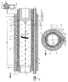
- FIG. 1 a longitudinal section through a backwash filter and Fig. 2 a cross section through the same along the line II-II of Fig. 1 according to a first embodiment of a backwash filter.
- the FIGS. 13 and 14 Show detergent supply channels or Spülstoffabbowkanäle in the removed state in view.
- the FIGS. 15 and 16 illustrate a variant in longitudinal section ( Fig. 15 ) and cross section ( Fig. 16 ).
- a backwash filter is in a cylinder jacket-shaped housing 1 is also a cylinder jacket-shaped Filter body 2 rotatably mounted, wherein the housing 1 is arranged stationary.
- the rotary drive 3 for the filter body 2 is realized by an electric motor 4, which drives the filter body 2 via a gear transmission 5.
- the backwash filter is provided with a vent and has a control device for controlling the pressures.
- the housing 1 is heated; the heating cables are labeled H.
- the filter body 2 itself has an over the entire circumference externally extending pressure plate 6, optionally composed of segments, and an inner also extending over the entire circumference supporting plate 7, between which the filter material 8 is inserted. Both the pressure plate and the support plate are provided with radially directed openings 9, so that a medium can flow through the openings 9 while passing through the filter material 8. These openings 9 are illustrated only at one end of the filter body 2, but are provided over its entire longitudinal extent 20. By longitudinal extent 20 of the filter body 2 is meant that length over which the filter material 8 extends. Various supporting surfaces 2 'for supporting the filter body are not taken into account here.
- a flushing agent removal channel 10 extends along a generatrix of the filter body 2.
- the flushing agent removal channel 10 is formed by a rotatably mounted tube 11, which can likewise be driven by an electric motor 12 via a gear 13 and tangentially contacts the filter body 2 on the outside, ie on the outside of the pressure plate 6.
- This tube 11 extends over the entire longitudinal extension 20 of the filter body 2 and is rotatably mounted in the housing 1.
- a Mediumzuströmraum 14 is formed, which is supplied via an inlet 15 with fresh, still to be cleaned medium.
- the interior 16 of the filter body 2 forms the medium outflow space for the filtered medium, which flows filtered medium through a discharge channel 17.
- the tube 11 has a slot 18 extending over its entire length, which connects the interior of the tube 11, that is to say the flushing agent removal channel 10, with its outer space and which extends in a helical manner over the wall of the tube 11.
- the filter body 2 is also rotated continuously or discontinuously.
- the discontinuous rotation can be controlled by the pressure curve, so that as constant pressure as possible operation takes place.
- the rotation of the filter body 2 may be stepwise (e.g., 5 ° each).
- the flushing agent drainage channel 10, ie the tube 11, can be provided with a slot 18 which is provided in a helical manner along the tube 11 or else a slot 18 which extends in a helical manner over the tube 11 in two or more directions.
- a double-flighted slot 18 is in Fig. 14 illustrated.
- Fig. 13 shows analogously to the representation in Fig. 1 a catchy slot 18.
- the Spülschabbowkanal 10 ie the tube 11, non-rotatably mounted in the housing 1, but longitudinally displaceable and has a directed radially against the filter body 2 scavenging port 23.
- This flushing opening 23 has a longitudinal extension 21, that is to say an extension parallel to a generatrix of the filter body 2, which is substantially smaller than the longitudinal extension 20 of the filter body 2.
- a displacement device 25 for the flushing agent removal channel 10 is shown in FIG Fig. 3 indicated schematically.
- the flushing opening 23 can be continuously or discontinuously displaced from one end of the filter body 2 to the other end of the filter body 2 over its longitudinal extension 20 and beyond, so that in turn all openings 9 of a generatrix of the filter body 2 are gradually cleaned.
- FIGS. 5 and 6 illustrated variant of a backwash filter corresponds substantially to the in the Fig. 1 and 2 illustrated embodiment, with the exception of a detergent supply channel 26 which is provided in the interior of the filter body 2, ie in the medium outflow space 16, and has a longitudinal slot 27 which extends over the entire longitudinal extent 20 of the filter body 2.
- the detergent supply channel 26 is provided stationary and therefore in a stationary insert body 31, against which the filter body is rotatable arranged. This makes it possible to use a detergent with an independent of the pressure of the purified medium pressure for cleaning the filter material 8.
- a booster pump 28 provided in a conduit 29 supplying the purified medium to the rinse medium supply passage 26 is shown in FIG Fig. 5 illustrated schematically. Instead of the booster pump 28, a piston pressure system can also be used.
- FIGS. 7 and 8 show a backwash filter variant, according to which a detergent supply channel 26, as in the FIGS. 5 and 6 is illustrated, is provided, however, the Spülschabbowkanal 10 analogous to that in the 3 and 4 variant shown provided longitudinally displaceable.
- FIGS. 9 and 10 show a variant according to which the flushing agent removal channel 10 has a over the entire length of the filter body 2 extending rectilinear slot 32 which is fixed and aligned directly against the filter body 2.
- a detergent supply channel 26 is here formed by a rotatable tube 30, which is analogous to the detergent discharge channel 10 of the in the Fig. 1 and 2 illustrated variant, ie is called the tube 11, is designed. It has a helically extending over its length slot 18 (one, two or more continuous), whereby the filter body 2, that is, the openings 9, are acted upon only by a short longitudinal extension 21 with detergent.
- continuous or discontinuous rotation of the tube 30, succeeds in cleaning the filter body 2 over the entire longitudinal extension 20 of one of its generatrices.
- the detergent removal channel 10 here also has a slot 32 extending over the entire longitudinal extent 20 of the filter body 2.
- the insert body 31 are also supported stationary.
- the detergent removal channel 10 is formed as in the in the Fig. 9 to 12 A flow connection for the rinsing agent, which extends only over a portion of the solution extension 20, by means of a slide 33 which covers the slot 32, however, a rinsing opening 23 which extends over the entire longitudinal extent 20th is movable, has achieved.
- the invention can be used in particular for lyocell technology.
- the backwash filter can at appropriate locations leakage openings analogous to EP 0 781 356 A1 exhibit.
Claims (9)
- Filtre à rétrolavage, destiné en particulier à des fluides hautement visqueux, avec un corps de filtre (2) prévu dans un boîtier (1) et formant une enveloppe cylindrique, le boîtier (1) et le corps de filtre (2) étant rotatifs l'un par rapport à l'autre autour de l'axe du corps de filtre (2), le corps de filtre (2) séparant un compartiment d'admission de fluide (14) d'un compartiment d'évacuation de fluide (16), et avec un canal de sortie (10) de liquide de rinçage s'étendant le long d'une génératrice du corps de filtre (2), mobile par rapport au corps de filtre (2) et pouvant être mis en liaison d'écoulement avec le corps de filtre (2) sur toute la longueur et sur toute la périphérie de celui-ci par formation d'un courant de liquide de rinçage débouchant dans le canal de sortie (10) de liquide de rinçage, la liaison d'écoulement n'étant toujours réalisée que sur une partie de l'extension longitudinale (20) d'une génératrice du corps de filtre (2), caractérisé en ce que le canal de sortie (10) de liquide de rinçage est rendu étanche par des joints (22) par rapport au corps de filtre (2) de part et d'autre de la génératrice le long de laquelle le canal de sortie (10) de liquide de rinçage contacte le corps de filtre (2), en ce que le corps de filtre (2) comporte une plaque de pression (6) et une plaque d'appui (7) ainsi qu'un matériau de filtre (8) disposé entre celles-ci, et en ce que le corps de filtre (2) est monté de manière rotative par rapport au boîtier fixe (1), une amenée (15) pour le fluide à filtrer dans le boîtier (1) étant dans le sens de rotation (19) du corps de filtre (2) prévue directement contiguë au canal de sortie (10) de liquide de rinçage.
- Filtre à rétrolavage selon la revendication 1, caractérisé en ce que le compartiment d'admission de fluide (14) est formé entre le boîtier (1) et le corps de filtre (2), et le compartiment d'évacuation de fluide (16) est formé à l'intérieur du corps de filtre (2), le canal de sortie (10) de liquide de rinçage étant prévu à l'extérieur du corps de filtre (2).
- Filtre à rétrolavage selon la revendication 1 ou 2, caractérisé en ce que le canal de sortie (10) de liquide de rinçage est formé par un conduit (11) monté de manière rotative autour de son axe longitudinal, lequel est pourvu d'une fente (18) s'étendant sur la paroi du conduit (11) suivant un tracé hélicoïdal et reliant l'intérieur du conduit (11) à l'extérieur de celui-ci, la surface extérieure du conduit (11) contactant le corps de filtre (2) sur toute son extension longitudinale (20).
- Filtre à rétrolavage selon la revendication 1 ou 2, caractérisé en ce que le canal de sortie (10) de liquide de rinçage est formé par un conduit (11) mobile le long de son axe longitudinal, lequel présente une ouverture de rinçage (23) radiale reliant l'intérieur à l'extérieur du conduit, ladite ouverture de rinçage (23) présentant une extension (21) le long de l'axe longitudinal du conduit (11) inférieure à l'extension longitudinale (20) du corps de filtre (2), la surface extérieure du conduit (11) contactant préférentiellement le corps de filtre (2) sur toute son extension longitudinale (20) et l'ouverture de rinçage (23) étant dirigée vers le corps de filtre (2).
- Filtre à rétrolavage selon l'une des revendications 3 ou 4, caractérisé en ce qu'à l'intérieur du corps de filtre (2) est prévu un canal d'amenée (26) de liquide de rinçage vis-à-vis du canal de sortie (10) de liquide de rinçage prévu en dehors du corps de filtre (2), ledit canal d'amenée (26) de liquide de rinçage présentant une fente longitudinale (27) dirigée vers le canal de sortie (10) de liquide de rinçage et s'étendant sur toute l'extension longitudinale (20) du corps de filtre (2).
- Filtre à rétrolavage selon la revendication 1 ou 2, caractérisé en ce que le canal de sortie (10) de liquide de rinçage présente une fente longitudinale (32) qui s'étend sur toute l'extension longitudinale (20) du corps de filtre (2), et en ce qu'est prévu un canal d'amenée (26) de liquide de rinçage disposé vis-à-vis du canal de sortie (10) de liquide de rinçage, lequel est formé par un conduit (30) monté de manière rotative autour de son axe longitudinal, pourvu d'une fente (18) s'étendant sur la paroi du conduit (30) suivant un tracé hélicoïdal et reliant l'intérieur du conduit (30) à l'extérieur de celui-ci, la surface extérieure du conduit (30) contactant le corps de filtre (2) sur toute son extension longitudinale (20).
- Filtre à rétrolavage selon la revendication 1 ou 2, caractérisé en ce que le canal de sortie (10) de liquide de rinçage est pourvu d'une fente (32) s'étendant sur toute l'extension longitudinale (20) du corps de filtre (2) et en ce qu'un canal d'amenée (26) de liquide de rinçage est prévu vis-à-vis du canal de sortie (10) de liquide de rinçage, lequel est formé par un conduit (11) monté de manière rotative autour de son axe longitudinal, présentant une ouverture de rinçage (23) dirigée radialement vers la fente (32) du canal de sortie (10) de liquide de rinçage et mobile avec cette ouverture de rinçage (23) d'une extrémité du corps de filtre (2) à l'autre extrémité du corps de filtre (2) et au-delà, l'ouverture de rinçage (23) présentant dans la direction de l'axe longitudinal du conduit (11) une extension (21) inférieure à l'extension longitudinale (20) du corps de filtre (2).
- Filtre à rétrolavage selon l'une des revendications 3 à 7, caractérisé en ce que la fente (18) à tracé hélicoïdal est double.
- Filtre à rétrolavage selon l'une des revendications 1 à 8, caractérisé en ce que la partie de la liaison d'écoulement s'étend au maximum sur 20 %, préférentiellement au maximum 5 % de l'extension longitudinale (20) du corps de filtre (2).
Priority Applications (1)
| Application Number | Priority Date | Filing Date | Title |
|---|---|---|---|
| SI200831716A SI2125146T1 (sl) | 2007-01-18 | 2008-01-17 | Povratno splakovalni filter |
Applications Claiming Priority (2)
| Application Number | Priority Date | Filing Date | Title |
|---|---|---|---|
| AT0009407A AT504361B8 (de) | 2007-01-18 | 2007-01-18 | Rückspülfilter |
| PCT/AT2008/000012 WO2008086554A1 (fr) | 2007-01-18 | 2008-01-17 | Filtre à rétrolavage |
Publications (2)
| Publication Number | Publication Date |
|---|---|
| EP2125146A1 EP2125146A1 (fr) | 2009-12-02 |
| EP2125146B1 true EP2125146B1 (fr) | 2016-08-31 |
Family
ID=39272412
Family Applications (1)
| Application Number | Title | Priority Date | Filing Date |
|---|---|---|---|
| EP08700279.6A Active EP2125146B1 (fr) | 2007-01-18 | 2008-01-17 | Filtre à rétrolavage |
Country Status (8)
| Country | Link |
|---|---|
| US (1) | US8579119B2 (fr) |
| EP (1) | EP2125146B1 (fr) |
| KR (1) | KR101491544B1 (fr) |
| CN (2) | CN101610826A (fr) |
| AT (1) | AT504361B8 (fr) |
| HU (1) | HUE032073T2 (fr) |
| SI (1) | SI2125146T1 (fr) |
| WO (1) | WO2008086554A1 (fr) |
Families Citing this family (14)
| Publication number | Priority date | Publication date | Assignee | Title |
|---|---|---|---|---|
| CN102039064B (zh) * | 2009-10-10 | 2012-08-29 | 新疆天业(集团)有限公司 | 分度旋转式自清洗过滤器 |
| AT511426B1 (de) | 2011-04-05 | 2017-02-15 | E Hawle Armaturenwerke Gmbh | Wasseraufbereitungsanlage |
| CN102921208B (zh) * | 2012-10-29 | 2014-09-10 | 济南大学 | 高效连续式反粒度过滤装置及工艺 |
| CN104107570B (zh) * | 2014-07-28 | 2016-08-24 | 北京中天油石油天然气科技有限公司 | 一种卧式滚筒多级填料过滤器 |
| KR101605518B1 (ko) * | 2014-10-24 | 2016-03-22 | 주식회사 센플러스 | 미소입자의 자기 배열을 위한 장치 및 방법 |
| CN105727616A (zh) * | 2014-12-11 | 2016-07-06 | 阿力甫江·阿不里米提 | 5寸鱼雷除砂网式全自动冲洗过滤器 |
| CN106139672A (zh) * | 2015-04-15 | 2016-11-23 | 巩高铄 | 一种管式过滤机及采用这种管式过滤机的物料分离系统 |
| CN105817089B (zh) * | 2016-04-18 | 2018-08-17 | 成都易态科技有限公司 | 一种过滤元件及过滤装置 |
| EP3263203A1 (fr) | 2016-07-01 | 2018-01-03 | BWT Aktiengesellschaft | Filtre de retrolavage |
| CN105999817A (zh) * | 2016-07-27 | 2016-10-12 | 宁夏共享机床辅机有限公司 | 一种磨床用离心式楔形网自清洗过滤装置 |
| KR102160894B1 (ko) * | 2020-04-10 | 2020-09-29 | 주식회사 에싸 | 수중이물질을 여과, 분리, 탈수하는 다중구조의 여과장치 |
| CN111391273A (zh) * | 2020-04-17 | 2020-07-10 | 濮阳市中原石化实业有限公司 | 一种热塑性塑料挤出装置 |
| CN113797636A (zh) * | 2021-09-07 | 2021-12-17 | 江苏润云纺织科技有限公司 | 一种喷水织机用水循环机构 |
| CN113952785B (zh) * | 2021-11-24 | 2022-10-18 | 深圳市福昌发电路板有限公司 | 一种装饰印刷纸制作的污水处理装置 |
Family Cites Families (19)
| Publication number | Priority date | Publication date | Assignee | Title |
|---|---|---|---|---|
| US2650711A (en) * | 1951-06-27 | 1953-09-01 | Laurence B Gilcrest | Water cleaning apparatus |
| US3140995A (en) * | 1960-08-29 | 1964-07-14 | Kinney Eng Inc S P | Self-cleaning rotary strainer |
| US3574509A (en) * | 1969-02-14 | 1971-04-13 | Zurn Ind Inc | Backwash filter |
| US3622006A (en) * | 1969-10-20 | 1971-11-23 | Marc M Brunner | Self-cleaning strainer for pipeline |
| US5030347A (en) * | 1987-07-30 | 1991-07-09 | Mordeki Drori | Multiple filter elements with movable flushing assembly |
| IL94630A (en) * | 1990-06-06 | 1993-08-18 | Filtration Ltd Herzliya And Yt | Self-cleaning filter |
| AT395825B (de) * | 1991-03-25 | 1993-03-25 | Erema | Filtriervorrichtung fuer zu reinigende fluide |
| DE4116199A1 (de) * | 1991-05-17 | 1992-11-19 | Guenter Ing Grad Hartig | Vorrichtung zum reinigen von fluiden |
| DE19523462A1 (de) | 1995-06-28 | 1997-01-02 | Knecht Filterwerke Gmbh | Rückspülbares Filter für Flüssigkeiten |
| AT408547B (de) | 1995-09-26 | 2001-12-27 | Chemiefaser Lenzing Ag | Verfahren zum transportieren einer lösung von cellulose in einem wässrigen tertiären aminoxid |
| ATE235944T1 (de) * | 1996-12-28 | 2003-04-15 | Mahle Filtersysteme Gmbh | Filter für verunreinigungen enthaltende flüssigkeiten |
| DE19803083A1 (de) | 1998-01-28 | 1999-07-29 | Knecht Filterwerke Gmbh | Rückspülbares Filter für Verunreinigungen enthaltende Flüssigkeiten |
| JPH11314015A (ja) * | 1998-05-06 | 1999-11-16 | Tadayoshi Nagaoka | 濾過装置 |
| US6267879B1 (en) | 1999-08-11 | 2001-07-31 | Odis Irrigation Equipment Ltd. | Continuous liquid filtering apparatus with multi-layer sintered filtering element |
| AT4594U1 (de) | 2000-01-17 | 2001-09-25 | Lenzing Technik Gmbh & Co Kg | Rückspülbares filter für flüssigkeiten |
| AT408522B (de) * | 2000-05-10 | 2001-12-27 | Econ Maschb Und Steuerungstech | Filtersystem zur reinigung von kunststoffschmelzen |
| DE20014299U1 (de) | 2000-08-15 | 2002-01-03 | Boll & Kirch Filter | Rückspülfilter für flüssige Medien |
| DE10252785B4 (de) | 2002-11-13 | 2011-04-07 | Mahle Filtersysteme Gmbh | Selbstreinigendes Flüssigkeitsfilter |
| DE102004049643A1 (de) * | 2004-10-11 | 2006-04-20 | Plastmachines International Gmbh | Filtervorrichtung für eine Verarbeitungsanlage von thermoplastischen Kunststoff sowie Filterverfahren |
-
2007
- 2007-01-18 AT AT0009407A patent/AT504361B8/de active
-
2008
- 2008-01-17 EP EP08700279.6A patent/EP2125146B1/fr active Active
- 2008-01-17 CN CNA2008800024437A patent/CN101610826A/zh active Pending
- 2008-01-17 CN CN201410393104.3A patent/CN104128032B/zh active Active
- 2008-01-17 WO PCT/AT2008/000012 patent/WO2008086554A1/fr active Application Filing
- 2008-01-17 SI SI200831716A patent/SI2125146T1/sl unknown
- 2008-01-17 KR KR1020097015598A patent/KR101491544B1/ko active IP Right Grant
- 2008-01-17 HU HUE08700279A patent/HUE032073T2/en unknown
- 2008-01-17 US US12/522,992 patent/US8579119B2/en active Active
Also Published As
| Publication number | Publication date |
|---|---|
| US8579119B2 (en) | 2013-11-12 |
| CN104128032A (zh) | 2014-11-05 |
| KR101491544B1 (ko) | 2015-02-09 |
| HUE032073T2 (en) | 2017-08-28 |
| AT504361B8 (de) | 2008-09-15 |
| EP2125146A1 (fr) | 2009-12-02 |
| KR20090107513A (ko) | 2009-10-13 |
| AT504361B1 (de) | 2008-05-15 |
| US20100065489A1 (en) | 2010-03-18 |
| SI2125146T1 (sl) | 2016-12-30 |
| AT504361A4 (de) | 2008-05-15 |
| CN101610826A (zh) | 2009-12-23 |
| WO2008086554A1 (fr) | 2008-07-24 |
| CN104128032B (zh) | 2016-05-11 |
Similar Documents
| Publication | Publication Date | Title |
|---|---|---|
| EP2125146B1 (fr) | Filtre à rétrolavage | |
| DE2629151C2 (de) | Rückspülbare Filtervorrichtung | |
| EP0656223B1 (fr) | Filtre à rinçage à contre-courant | |
| EP3525905A1 (fr) | Dispositif de filtration | |
| DE202009002823U1 (de) | Exzenterschneckenpumpe | |
| DE2946064A1 (de) | Filtereinrichtung | |
| DE102009049355A1 (de) | Filtriergerät für geschmolzenes Kunststoffmaterial | |
| EP3218162B1 (fr) | Dispositif et procédé de filtration pour la filtration d'un fluide | |
| WO2006045126A1 (fr) | Dispositif pour filtrer en continu des substances fluides contenant des particules de matiere solide | |
| EP0517945B1 (fr) | Appareil de filtration à nettoyage par contre-courrant | |
| EP2024650B1 (fr) | Système de fluide | |
| EP2686083B1 (fr) | Dispositif de filtration pour fluides de haute viscosité | |
| DE102007006448A1 (de) | Trommelfilter | |
| EP0577854A1 (fr) | Dispositif de filtration | |
| DE202012100368U1 (de) | Rückspülfilter | |
| EP2109489B1 (fr) | Filtre pour liquides dans des conduites | |
| DE102008063972A1 (de) | Filter zum Einsatz in der Schmelzkäseherstellung | |
| DD201854A5 (de) | Filterapparat zur abtrennung von fest- und schwebstoffen aus fluessigkeiten | |
| EP2175955B1 (fr) | Dispositif de lavage à contre-courant pour une installation de filtrage | |
| DE4017013C2 (de) | Vorrichtung zum Reinigen von Brunnenschächten | |
| DE202005019664U1 (de) | Rückspülfilter | |
| EP2039410A1 (fr) | Dispositif de filtre | |
| AT409223B (de) | Einrichtung zur reinigung, insbesondere zur filterung, von flüssigkeiten | |
| DE102005016151B4 (de) | Filtervorrichtung | |
| AT396874B (de) | Spaltfilter, vorzugsweise für hochviskose flüssigkeiten |
Legal Events
| Date | Code | Title | Description |
|---|---|---|---|
| PUAI | Public reference made under article 153(3) epc to a published international application that has entered the european phase |
Free format text: ORIGINAL CODE: 0009012 |
|
| 17P | Request for examination filed |
Effective date: 20090624 |
|
| AK | Designated contracting states |
Kind code of ref document: A1 Designated state(s): AT BE BG CH CY CZ DE DK EE ES FI FR GB GR HR HU IE IS IT LI LT LU LV MC MT NL NO PL PT RO SE SI SK TR |
|
| DAX | Request for extension of the european patent (deleted) | ||
| 17Q | First examination report despatched |
Effective date: 20140702 |
|
| GRAP | Despatch of communication of intention to grant a patent |
Free format text: ORIGINAL CODE: EPIDOSNIGR1 |
|
| INTG | Intention to grant announced |
Effective date: 20160419 |
|
| GRAS | Grant fee paid |
Free format text: ORIGINAL CODE: EPIDOSNIGR3 |
|
| GRAA | (expected) grant |
Free format text: ORIGINAL CODE: 0009210 |
|
| AK | Designated contracting states |
Kind code of ref document: B1 Designated state(s): AT BE BG CH CY CZ DE DK EE ES FI FR GB GR HR HU IE IS IT LI LT LU LV MC MT NL NO PL PT RO SE SI SK TR |
|
| REG | Reference to a national code |
Ref country code: CH Ref legal event code: EP Ref country code: GB Ref legal event code: FG4D Free format text: NOT ENGLISH |
|
| REG | Reference to a national code |
Ref country code: IE Ref legal event code: FG4D Free format text: LANGUAGE OF EP DOCUMENT: GERMAN |
|
| REG | Reference to a national code |
Ref country code: DE Ref legal event code: R096 Ref document number: 502008014574 Country of ref document: DE |
|
| REG | Reference to a national code |
Ref country code: AT Ref legal event code: REF Ref document number: 824504 Country of ref document: AT Kind code of ref document: T Effective date: 20161015 |
|
| REG | Reference to a national code |
Ref country code: CH Ref legal event code: NV Representative=s name: BOGENSBERGER PATENT- AND MARKENBUERO DR. BURKH, LI |
|
| REG | Reference to a national code |
Ref country code: SE Ref legal event code: TRGR |
|
| REG | Reference to a national code |
Ref country code: LT Ref legal event code: MG4D |
|
| REG | Reference to a national code |
Ref country code: NL Ref legal event code: MP Effective date: 20160831 |
|
| PG25 | Lapsed in a contracting state [announced via postgrant information from national office to epo] |
Ref country code: HR Free format text: LAPSE BECAUSE OF FAILURE TO SUBMIT A TRANSLATION OF THE DESCRIPTION OR TO PAY THE FEE WITHIN THE PRESCRIBED TIME-LIMIT Effective date: 20160831 Ref country code: NO Free format text: LAPSE BECAUSE OF FAILURE TO SUBMIT A TRANSLATION OF THE DESCRIPTION OR TO PAY THE FEE WITHIN THE PRESCRIBED TIME-LIMIT Effective date: 20161130 Ref country code: LT Free format text: LAPSE BECAUSE OF FAILURE TO SUBMIT A TRANSLATION OF THE DESCRIPTION OR TO PAY THE FEE WITHIN THE PRESCRIBED TIME-LIMIT Effective date: 20160831 |
|
| PG25 | Lapsed in a contracting state [announced via postgrant information from national office to epo] |
Ref country code: LV Free format text: LAPSE BECAUSE OF FAILURE TO SUBMIT A TRANSLATION OF THE DESCRIPTION OR TO PAY THE FEE WITHIN THE PRESCRIBED TIME-LIMIT Effective date: 20160831 Ref country code: GR Free format text: LAPSE BECAUSE OF FAILURE TO SUBMIT A TRANSLATION OF THE DESCRIPTION OR TO PAY THE FEE WITHIN THE PRESCRIBED TIME-LIMIT Effective date: 20161201 Ref country code: NL Free format text: LAPSE BECAUSE OF FAILURE TO SUBMIT A TRANSLATION OF THE DESCRIPTION OR TO PAY THE FEE WITHIN THE PRESCRIBED TIME-LIMIT Effective date: 20160831 Ref country code: ES Free format text: LAPSE BECAUSE OF FAILURE TO SUBMIT A TRANSLATION OF THE DESCRIPTION OR TO PAY THE FEE WITHIN THE PRESCRIBED TIME-LIMIT Effective date: 20160831 |
|
| PG25 | Lapsed in a contracting state [announced via postgrant information from national office to epo] |
Ref country code: RO Free format text: LAPSE BECAUSE OF FAILURE TO SUBMIT A TRANSLATION OF THE DESCRIPTION OR TO PAY THE FEE WITHIN THE PRESCRIBED TIME-LIMIT Effective date: 20160831 Ref country code: EE Free format text: LAPSE BECAUSE OF FAILURE TO SUBMIT A TRANSLATION OF THE DESCRIPTION OR TO PAY THE FEE WITHIN THE PRESCRIBED TIME-LIMIT Effective date: 20160831 |
|
| PG25 | Lapsed in a contracting state [announced via postgrant information from national office to epo] |
Ref country code: PT Free format text: LAPSE BECAUSE OF FAILURE TO SUBMIT A TRANSLATION OF THE DESCRIPTION OR TO PAY THE FEE WITHIN THE PRESCRIBED TIME-LIMIT Effective date: 20170102 Ref country code: DK Free format text: LAPSE BECAUSE OF FAILURE TO SUBMIT A TRANSLATION OF THE DESCRIPTION OR TO PAY THE FEE WITHIN THE PRESCRIBED TIME-LIMIT Effective date: 20160831 Ref country code: BG Free format text: LAPSE BECAUSE OF FAILURE TO SUBMIT A TRANSLATION OF THE DESCRIPTION OR TO PAY THE FEE WITHIN THE PRESCRIBED TIME-LIMIT Effective date: 20161130 Ref country code: BE Free format text: LAPSE BECAUSE OF NON-PAYMENT OF DUE FEES Effective date: 20170131 Ref country code: PL Free format text: LAPSE BECAUSE OF FAILURE TO SUBMIT A TRANSLATION OF THE DESCRIPTION OR TO PAY THE FEE WITHIN THE PRESCRIBED TIME-LIMIT Effective date: 20160831 |
|
| REG | Reference to a national code |
Ref country code: DE Ref legal event code: R097 Ref document number: 502008014574 Country of ref document: DE |
|
| REG | Reference to a national code |
Ref country code: SK Ref legal event code: T3 Ref document number: E 22832 Country of ref document: SK |
|
| PLBE | No opposition filed within time limit |
Free format text: ORIGINAL CODE: 0009261 |
|
| STAA | Information on the status of an ep patent application or granted ep patent |
Free format text: STATUS: NO OPPOSITION FILED WITHIN TIME LIMIT |
|
| 26N | No opposition filed |
Effective date: 20170601 |
|
| REG | Reference to a national code |
Ref country code: HU Ref legal event code: AG4A Ref document number: E032073 Country of ref document: HU |
|
| PG25 | Lapsed in a contracting state [announced via postgrant information from national office to epo] |
Ref country code: MC Free format text: LAPSE BECAUSE OF FAILURE TO SUBMIT A TRANSLATION OF THE DESCRIPTION OR TO PAY THE FEE WITHIN THE PRESCRIBED TIME-LIMIT Effective date: 20160831 |
|
| REG | Reference to a national code |
Ref country code: FR Ref legal event code: ST Effective date: 20170929 |
|
| PG25 | Lapsed in a contracting state [announced via postgrant information from national office to epo] |
Ref country code: FR Free format text: LAPSE BECAUSE OF NON-PAYMENT OF DUE FEES Effective date: 20170131 |
|
| REG | Reference to a national code |
Ref country code: IE Ref legal event code: MM4A |
|
| PG25 | Lapsed in a contracting state [announced via postgrant information from national office to epo] |
Ref country code: LU Free format text: LAPSE BECAUSE OF NON-PAYMENT OF DUE FEES Effective date: 20170117 |
|
| REG | Reference to a national code |
Ref country code: BE Ref legal event code: MM Effective date: 20170131 |
|
| PG25 | Lapsed in a contracting state [announced via postgrant information from national office to epo] |
Ref country code: IE Free format text: LAPSE BECAUSE OF NON-PAYMENT OF DUE FEES Effective date: 20170117 |
|
| REG | Reference to a national code |
Ref country code: AT Ref legal event code: MM01 Ref document number: 824504 Country of ref document: AT Kind code of ref document: T Effective date: 20170117 |
|
| PG25 | Lapsed in a contracting state [announced via postgrant information from national office to epo] |
Ref country code: AT Free format text: LAPSE BECAUSE OF NON-PAYMENT OF DUE FEES Effective date: 20170117 |
|
| PG25 | Lapsed in a contracting state [announced via postgrant information from national office to epo] |
Ref country code: MT Free format text: LAPSE BECAUSE OF FAILURE TO SUBMIT A TRANSLATION OF THE DESCRIPTION OR TO PAY THE FEE WITHIN THE PRESCRIBED TIME-LIMIT Effective date: 20160831 |
|
| PG25 | Lapsed in a contracting state [announced via postgrant information from national office to epo] |
Ref country code: CY Free format text: LAPSE BECAUSE OF NON-PAYMENT OF DUE FEES Effective date: 20160831 |
|
| PG25 | Lapsed in a contracting state [announced via postgrant information from national office to epo] |
Ref country code: IS Free format text: LAPSE BECAUSE OF FAILURE TO SUBMIT A TRANSLATION OF THE DESCRIPTION OR TO PAY THE FEE WITHIN THE PRESCRIBED TIME-LIMIT Effective date: 20161231 |
|
| PGFP | Annual fee paid to national office [announced via postgrant information from national office to epo] |
Ref country code: FI Payment date: 20230120 Year of fee payment: 16 Ref country code: CZ Payment date: 20230106 Year of fee payment: 16 Ref country code: CH Payment date: 20230119 Year of fee payment: 16 |
|
| PGFP | Annual fee paid to national office [announced via postgrant information from national office to epo] |
Ref country code: TR Payment date: 20230117 Year of fee payment: 16 Ref country code: SK Payment date: 20230110 Year of fee payment: 16 Ref country code: SI Payment date: 20230105 Year of fee payment: 16 Ref country code: SE Payment date: 20230119 Year of fee payment: 16 Ref country code: IT Payment date: 20230120 Year of fee payment: 16 Ref country code: HU Payment date: 20230123 Year of fee payment: 16 Ref country code: GB Payment date: 20230119 Year of fee payment: 16 Ref country code: DE Payment date: 20230123 Year of fee payment: 16 |
|
| P01 | Opt-out of the competence of the unified patent court (upc) registered |
Effective date: 20230714 |