EP2125146B1 - Backwash filter - Google Patents
Backwash filter Download PDFInfo
- Publication number
- EP2125146B1 EP2125146B1 EP08700279.6A EP08700279A EP2125146B1 EP 2125146 B1 EP2125146 B1 EP 2125146B1 EP 08700279 A EP08700279 A EP 08700279A EP 2125146 B1 EP2125146 B1 EP 2125146B1
- Authority
- EP
- European Patent Office
- Prior art keywords
- filter body
- flushing agent
- pipe
- discharge channel
- flushing
- Prior art date
- Legal status (The legal status is an assumption and is not a legal conclusion. Google has not performed a legal analysis and makes no representation as to the accuracy of the status listed.)
- Active
Links
Images


Classifications
-
- B—PERFORMING OPERATIONS; TRANSPORTING
- B01—PHYSICAL OR CHEMICAL PROCESSES OR APPARATUS IN GENERAL
- B01D—SEPARATION
- B01D33/00—Filters with filtering elements which move during the filtering operation
- B01D33/44—Regenerating the filter material in the filter
- B01D33/48—Regenerating the filter material in the filter by flushing, e.g. counter-current air-bumps
- B01D33/50—Regenerating the filter material in the filter by flushing, e.g. counter-current air-bumps with backwash arms, shoes or nozzles
-
- B—PERFORMING OPERATIONS; TRANSPORTING
- B01—PHYSICAL OR CHEMICAL PROCESSES OR APPARATUS IN GENERAL
- B01D—SEPARATION
- B01D33/00—Filters with filtering elements which move during the filtering operation
- B01D33/06—Filters with filtering elements which move during the filtering operation with rotary cylindrical filtering surfaces, e.g. hollow drums
- B01D33/073—Filters with filtering elements which move during the filtering operation with rotary cylindrical filtering surfaces, e.g. hollow drums arranged for inward flow filtration
-
- B—PERFORMING OPERATIONS; TRANSPORTING
- B01—PHYSICAL OR CHEMICAL PROCESSES OR APPARATUS IN GENERAL
- B01D—SEPARATION
- B01D33/00—Filters with filtering elements which move during the filtering operation
- B01D33/44—Regenerating the filter material in the filter
- B01D33/48—Regenerating the filter material in the filter by flushing, e.g. counter-current air-bumps
-
- B—PERFORMING OPERATIONS; TRANSPORTING
- B01—PHYSICAL OR CHEMICAL PROCESSES OR APPARATUS IN GENERAL
- B01D—SEPARATION
- B01D33/00—Filters with filtering elements which move during the filtering operation
- B01D33/70—Filters with filtering elements which move during the filtering operation having feed or discharge devices
- B01D33/76—Filters with filtering elements which move during the filtering operation having feed or discharge devices for discharging the filter cake, e.g. chutes
-
- B—PERFORMING OPERATIONS; TRANSPORTING
- B29—WORKING OF PLASTICS; WORKING OF SUBSTANCES IN A PLASTIC STATE IN GENERAL
- B29C—SHAPING OR JOINING OF PLASTICS; SHAPING OF MATERIAL IN A PLASTIC STATE, NOT OTHERWISE PROVIDED FOR; AFTER-TREATMENT OF THE SHAPED PRODUCTS, e.g. REPAIRING
- B29C48/00—Extrusion moulding, i.e. expressing the moulding material through a die or nozzle which imparts the desired form; Apparatus therefor
- B29C48/25—Component parts, details or accessories; Auxiliary operations
- B29C48/27—Cleaning; Purging; Avoiding contamination
- B29C48/2725—Cleaning; Purging; Avoiding contamination of filters
- B29C48/273—Cleaning; Purging; Avoiding contamination of filters using back flow
-
- B—PERFORMING OPERATIONS; TRANSPORTING
- B29—WORKING OF PLASTICS; WORKING OF SUBSTANCES IN A PLASTIC STATE IN GENERAL
- B29C—SHAPING OR JOINING OF PLASTICS; SHAPING OF MATERIAL IN A PLASTIC STATE, NOT OTHERWISE PROVIDED FOR; AFTER-TREATMENT OF THE SHAPED PRODUCTS, e.g. REPAIRING
- B29C48/00—Extrusion moulding, i.e. expressing the moulding material through a die or nozzle which imparts the desired form; Apparatus therefor
- B29C48/25—Component parts, details or accessories; Auxiliary operations
- B29C48/36—Means for plasticising or homogenising the moulding material or forcing it through the nozzle or die
- B29C48/50—Details of extruders
- B29C48/69—Filters or screens for the moulding material
- B29C48/694—Cylindrical or conical filters
Definitions
- the invention relates to a backwash filter, in particular for highly viscous media, provided in a housing, a cylinder jacket forming filter body, wherein the housing and the filter body about the axis of the filter body are rotatable relative to each other, the filter body separates a Mediumzuströmraum from a Mediumabströmraum, and with a along a generatrix of the filter body extending Spülstoffabbowkanal which is movable relative to the filter body and which can be brought into fluid communication with the filter body over its entire length and over its entire circumference to form a flowing into the Spülstoffabbowkanal flow of detergent.
- Backwash filters are known in many variants, such as from the US 5,268,095 , of the DE 200 14 299 U1 , of the DE 198 03 083 A1 , of the DE 195 23 462 A1 or the AT 004594 U1 . All of these known backwashing filters have a housing in which a cylinder jacket-shaped filter body is provided, which filter body separates a medium inlet space from a medium discharge space. The medium to be filtered thus flows through the filter body as a result of a pressure difference and is thereby cleaned of impurities. The impurities settle on the side of the Mediumzuströmraumes on the filter body or filter material and must be removed after a certain time from the filter body, which is effected by a backwash.
- This backwashing is done according to the document DE 195 23 462 A1 via a flushing channel provided in the medium outflow chamber, which extends along the filter body and is movable relative to its circumference, whereby the filter body rotating around its longitudinal axis is successively cleaned along its generatrices over its entire length by cleaning, ie already filtered, medium over the filter body Filter body flows in the direction opposite to the flow of the uncleaned medium direction in the detergent discharge channel.
- a detergent supply channel which extends along a generatrix of the filter body and rinsing agent to a vis-a-vis arranged Spülstoffabschreibkanal passes over the filter body, wherein the filter body is cleaned along a generatrix over its entire length.
- the filter body is cleaned over its entire circumference.
- Backwash filters of this type have the disadvantage that relatively high amounts of backwashing liquid are needed. Since the filter body is cleaned over its entire length in one, as in the DE 195 23 462 A1 and the DE 198 03 083 A1 is shown, the efficiency of the backwash filter drops considerably.
- the known backwash filters are therefore suitable only for low-viscosity media. Furthermore, a relatively high pressure difference is required for the cleaning of the filter body, which heavily loads the filter material, which is supported by the filter body.
- the invention aims to avoid the above-described disadvantages and difficulties and has set itself the task of creating a backwash filter of the type described above, which finds the Aus GmbH with a low flushing volume.
- a more efficient rinsing of the filter material should be possible with the least possible mechanical engineering effort, so that even very fine filter materials can be used for backwash filters.
- This particularly good flushing should not be caused by an increased overpressure, which would be necessary in Huntêtfiltern according to the prior art, but are also effected at a low pressure difference on the filter body between the Spülstoffzstrom and the Spülstoffabströmung.
- it should be possible, due to the small difference in pressure to provide larger, free filter material surfaces which are not covered by supporting surfaces of the filter body, so that the backwash filter enables a substantially greater throughput.
- This object is achieved in that the flow connection always takes place only over a portion of the longitudinal extent of a generatrix of the filter body.
- the medium inlet space between the housing and the filter body and the medium outflow space is formed in the interior of the filter body, wherein the Spülstoffabschreibkanal is provided outside of the filter body.
- the Spülschabschreibkanal is formed by a rotatably mounted about its longitudinal axis tube which is provided with a helically extending over the wall of the tube and connecting the interior of the tube with the outer space slot, the outer surface of the tube contacts the filter body over its entire longitudinal extent ,
- the purified medium can be used as a backwash liquid, with only a small amount of the same at high Backwashing effect is needed, since this medium only passes over a very small length of a generatrix of the filter body in the detergent discharge channel.
- the Spülschabbowkanal is formed by a displaceable along its longitudinal axis tube having a radially directed, its interior communicating with its outer space scavenging port, which scavenging port has an extension along the longitudinal axis of the tube is smaller than the longitudinal extent of the filter body, wherein preferably the outer surface of the tube contacts the filter body over its entire longitudinal extent and the flushing opening is directed against the filter body.
- a rinsing agent supply channel is advantageously provided inside the filter body vis-à-vis the rinsing agent removal channel provided outside the filter body, the rinsing agent supply channel being a longitudinal slit directed towards the rinsing agent removal channel extends over the entire longitudinal extent of the filter body has.
- the detergent discharge channel has a longitudinal slot which extends over the entire longitudinal extension of the filter body, and there is provided a vis-a-vis the Spülstoffabbowkanal arranged Spülstoffzuschreibkanal formed by a rotatably mounted about its longitudinal axis tube, the is provided with a helically extending over the wall of the tube and connecting the interior of the tube with its outer space slot, wherein the outer surface of the tube contacts the filter body over its entire longitudinal extent.
- the detergent pressure is independent of the pressure of the filtered medium and it can also be used a detergent other than the filtered medium.
- the flushing agent removal channel is sealed against the filter body on both sides of the generatrix, along which the flushing agent removal channel contacts the filter body, by means of seals
- the filter body has a pressure plate and a support plate and a filter material arranged therebetween
- the filter body is rotatably mounted relative to the stationary housing, wherein an inlet for medium to be filtered in the housing in the direction of rotation of the filter body is provided immediately adjacent to the detergent discharge channel.
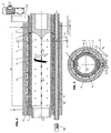
- FIG. 1 a longitudinal section through a backwash filter and Fig. 2 a cross section through the same along the line II-II of Fig. 1 according to a first embodiment of a backwash filter.
- the FIGS. 13 and 14 Show detergent supply channels or Spülstoffabbowkanäle in the removed state in view.
- the FIGS. 15 and 16 illustrate a variant in longitudinal section ( Fig. 15 ) and cross section ( Fig. 16 ).
- a backwash filter is in a cylinder jacket-shaped housing 1 is also a cylinder jacket-shaped Filter body 2 rotatably mounted, wherein the housing 1 is arranged stationary.
- the rotary drive 3 for the filter body 2 is realized by an electric motor 4, which drives the filter body 2 via a gear transmission 5.
- the backwash filter is provided with a vent and has a control device for controlling the pressures.
- the housing 1 is heated; the heating cables are labeled H.
- the filter body 2 itself has an over the entire circumference externally extending pressure plate 6, optionally composed of segments, and an inner also extending over the entire circumference supporting plate 7, between which the filter material 8 is inserted. Both the pressure plate and the support plate are provided with radially directed openings 9, so that a medium can flow through the openings 9 while passing through the filter material 8. These openings 9 are illustrated only at one end of the filter body 2, but are provided over its entire longitudinal extent 20. By longitudinal extent 20 of the filter body 2 is meant that length over which the filter material 8 extends. Various supporting surfaces 2 'for supporting the filter body are not taken into account here.
- a flushing agent removal channel 10 extends along a generatrix of the filter body 2.
- the flushing agent removal channel 10 is formed by a rotatably mounted tube 11, which can likewise be driven by an electric motor 12 via a gear 13 and tangentially contacts the filter body 2 on the outside, ie on the outside of the pressure plate 6.
- This tube 11 extends over the entire longitudinal extension 20 of the filter body 2 and is rotatably mounted in the housing 1.
- a Mediumzuströmraum 14 is formed, which is supplied via an inlet 15 with fresh, still to be cleaned medium.
- the interior 16 of the filter body 2 forms the medium outflow space for the filtered medium, which flows filtered medium through a discharge channel 17.
- the tube 11 has a slot 18 extending over its entire length, which connects the interior of the tube 11, that is to say the flushing agent removal channel 10, with its outer space and which extends in a helical manner over the wall of the tube 11.
- the filter body 2 is also rotated continuously or discontinuously.
- the discontinuous rotation can be controlled by the pressure curve, so that as constant pressure as possible operation takes place.
- the rotation of the filter body 2 may be stepwise (e.g., 5 ° each).
- the flushing agent drainage channel 10, ie the tube 11, can be provided with a slot 18 which is provided in a helical manner along the tube 11 or else a slot 18 which extends in a helical manner over the tube 11 in two or more directions.
- a double-flighted slot 18 is in Fig. 14 illustrated.
- Fig. 13 shows analogously to the representation in Fig. 1 a catchy slot 18.
- the Spülschabbowkanal 10 ie the tube 11, non-rotatably mounted in the housing 1, but longitudinally displaceable and has a directed radially against the filter body 2 scavenging port 23.
- This flushing opening 23 has a longitudinal extension 21, that is to say an extension parallel to a generatrix of the filter body 2, which is substantially smaller than the longitudinal extension 20 of the filter body 2.
- a displacement device 25 for the flushing agent removal channel 10 is shown in FIG Fig. 3 indicated schematically.
- the flushing opening 23 can be continuously or discontinuously displaced from one end of the filter body 2 to the other end of the filter body 2 over its longitudinal extension 20 and beyond, so that in turn all openings 9 of a generatrix of the filter body 2 are gradually cleaned.
- FIGS. 5 and 6 illustrated variant of a backwash filter corresponds substantially to the in the Fig. 1 and 2 illustrated embodiment, with the exception of a detergent supply channel 26 which is provided in the interior of the filter body 2, ie in the medium outflow space 16, and has a longitudinal slot 27 which extends over the entire longitudinal extent 20 of the filter body 2.
- the detergent supply channel 26 is provided stationary and therefore in a stationary insert body 31, against which the filter body is rotatable arranged. This makes it possible to use a detergent with an independent of the pressure of the purified medium pressure for cleaning the filter material 8.
- a booster pump 28 provided in a conduit 29 supplying the purified medium to the rinse medium supply passage 26 is shown in FIG Fig. 5 illustrated schematically. Instead of the booster pump 28, a piston pressure system can also be used.
- FIGS. 7 and 8 show a backwash filter variant, according to which a detergent supply channel 26, as in the FIGS. 5 and 6 is illustrated, is provided, however, the Spülschabbowkanal 10 analogous to that in the 3 and 4 variant shown provided longitudinally displaceable.
- FIGS. 9 and 10 show a variant according to which the flushing agent removal channel 10 has a over the entire length of the filter body 2 extending rectilinear slot 32 which is fixed and aligned directly against the filter body 2.
- a detergent supply channel 26 is here formed by a rotatable tube 30, which is analogous to the detergent discharge channel 10 of the in the Fig. 1 and 2 illustrated variant, ie is called the tube 11, is designed. It has a helically extending over its length slot 18 (one, two or more continuous), whereby the filter body 2, that is, the openings 9, are acted upon only by a short longitudinal extension 21 with detergent.
- continuous or discontinuous rotation of the tube 30, succeeds in cleaning the filter body 2 over the entire longitudinal extension 20 of one of its generatrices.
- the detergent removal channel 10 here also has a slot 32 extending over the entire longitudinal extent 20 of the filter body 2.
- the insert body 31 are also supported stationary.
- the detergent removal channel 10 is formed as in the in the Fig. 9 to 12 A flow connection for the rinsing agent, which extends only over a portion of the solution extension 20, by means of a slide 33 which covers the slot 32, however, a rinsing opening 23 which extends over the entire longitudinal extent 20th is movable, has achieved.
- the invention can be used in particular for lyocell technology.
- the backwash filter can at appropriate locations leakage openings analogous to EP 0 781 356 A1 exhibit.
Description
Die Erfindung betrifft ein Rückspülfilter, insbesondere für hochviskose Medien, mit in einem Gehäuse vorgesehenen, einen Zylindermantel bildenden Filterkörper, wobei das Gehäuse und der Filterkörper um die Achse des Filterkörpers relativ zueinander drehbar sind, der Filterkörper einen Mediumzuströmraum von einem Mediumabströmraum trennt, und mit einem längs einer Erzeugenden des Filterkörpers verlaufenden Spülmittelabfuhrkanal, der relativ gegenüber dem Filterkörper bewegbar ist und der mit dem Filterkörper über dessen gesamte Länge und über dessen gesamten Umfang unter Ausbildung einer in den Spülmittelabfuhrkanal mündenden Strömung von Spülmittel in Strömungsverbindung bringbar ist.The invention relates to a backwash filter, in particular for highly viscous media, provided in a housing, a cylinder jacket forming filter body, wherein the housing and the filter body about the axis of the filter body are rotatable relative to each other, the filter body separates a Mediumzuströmraum from a Mediumabströmraum, and with a along a generatrix of the filter body extending Spülmittelabfuhrkanal which is movable relative to the filter body and which can be brought into fluid communication with the filter body over its entire length and over its entire circumference to form a flowing into the Spülmittelabfuhrkanal flow of detergent.
Rückspülfilter sind in vielen Varianten bekannt, so z.B. aus der
Gemäß der
According to the
Rückspülfilter dieser Art weisen den Nachteil auf, dass relativ hohe Mengen an Rückspülflüssigkeit benötigt werden. Da der Filterkörper über seine gesamte Länge in einem gereinigt wird, wie dies in der
Die Erfindung bezweckt die Vermeidung der oben geschilderten Nachteile und Schwierigkeiten und stellt sich die Aufgabe, ein Rückspülfilter der eingangs beschriebenen Art zu schaffen, welches mit einem geringen Spülvolumen das Auslangen findet. Zudem soll mit möglichst geringem maschinenbaulichen Aufwand eine effizientere Spülung des Filtermaterials möglich sein, sodass auch besonders feine Filtermaterialien für Rückspülfilter einsetzbar sind. Diese besonders gute Spülung soll nicht durch einen erhöhten Überdruck bewirkt werden, was bei Rückspülfiltern gemäß dem Stand der Technik notwendig wäre, sondern auch bei einem geringen Druckunterschied am Filterkörper zwischen der Spülmittelzuströmung und der Spülmittelabströmung bewirkt werden. Zudem soll es möglich sein, durch den geringen Druckunterschied größere freie Filtermaterialflächen, die nicht von Stützflächen des Filterkörpers bedeckt sind, zur Verfügung zu stellen, sodass das Rückspülfilter eine wesentlich größere Durchsatzleistung ermöglicht.The invention aims to avoid the above-described disadvantages and difficulties and has set itself the task of creating a backwash filter of the type described above, which finds the Auslangen with a low flushing volume. In addition, a more efficient rinsing of the filter material should be possible with the least possible mechanical engineering effort, so that even very fine filter materials can be used for backwash filters. This particularly good flushing should not be caused by an increased overpressure, which would be necessary in Rückspülfiltern according to the prior art, but are also effected at a low pressure difference on the filter body between the Spülmittelzstrom and the Spülmittelabströmung. In addition, it should be possible, due to the small difference in pressure, to provide larger, free filter material surfaces which are not covered by supporting surfaces of the filter body, so that the backwash filter enables a substantially greater throughput.
Diese Aufgabe wird erfindungsgemäß dadurch gelöst, dass die Strömungsverbindung stets nur über einen Teilbereich der Längserstreckung einer Erzeugenden des Filterkörpers erfolgt.This object is achieved in that the flow connection always takes place only over a portion of the longitudinal extent of a generatrix of the filter body.
Gemäß einer bevorzugten Ausführungsform ist der Mediumzuströmraum zwischen dem Gehäuse und dem Filterkörper und der Mediumabströmraum im Inneren des Filterkörpers ausgebildet, wobei der Spülmittelabfuhrkanal außerhalb des Filterkörpers vorgesehen ist.According to a preferred embodiment, the medium inlet space between the housing and the filter body and the medium outflow space is formed in the interior of the filter body, wherein the Spülmittelabfuhrkanal is provided outside of the filter body.
Vorzugsweise ist der Spülmittelabfuhrkanal von einem um seine Längsachse drehbar gelagerten Rohr gebildet, das mit einem sich über die Wand des Rohres schraubenlinienförmig erstreckenden und den Innenraum des Rohres mit dessen Außenraum verbindenden Schlitz versehen ist, wobei die Außenoberfläche des Rohres den Filterkörper über dessen gesamte Längserstreckung kontaktiert. Hierbei lässt sich das gereinigte Medium als Rückspülflüssigkeit einsetzen, wobei nur eine geringe Menge desselben bei hoher Rückspülwirkung benötigt wird, da dieses Medium nur über eine sehr geringe Länge einer Erzeugenden des Filterkörpers in den Spülmittelabfuhrkanal gelangt.Preferably, the Spülmittelabfuhrkanal is formed by a rotatably mounted about its longitudinal axis tube which is provided with a helically extending over the wall of the tube and connecting the interior of the tube with the outer space slot, the outer surface of the tube contacts the filter body over its entire longitudinal extent , Here, the purified medium can be used as a backwash liquid, with only a small amount of the same at high Backwashing effect is needed, since this medium only passes over a very small length of a generatrix of the filter body in the detergent discharge channel.
Derselbe Vorteil lässt sich gemäß einer anderen Ausführungsform dadurch erzielen, dass der Spülmittelabfuhrkanal von einem entlang seiner Längsachse verschiebbaren Rohr gebildet ist, das eine radial gerichtete, seinen Innenraum mit seinem Außenraum verbindende Spülöffnung aufweist, welche Spülöffnung eine Erstreckung längs der Längsachse des Rohres aufweist, die geringer ist als die Längserstreckung des Filterkörpers, wobei vorzugsweise die Außenoberfläche des Rohres den Filterkörper über dessen gesamte Längserstreckung kontaktiert und die Spülöffnung gegen den Filterkörper gerichtet ist.The same advantage can be achieved according to another embodiment in that the Spülmittelabfuhrkanal is formed by a displaceable along its longitudinal axis tube having a radially directed, its interior communicating with its outer space scavenging port, which scavenging port has an extension along the longitudinal axis of the tube is smaller than the longitudinal extent of the filter body, wherein preferably the outer surface of the tube contacts the filter body over its entire longitudinal extent and the flushing opening is directed against the filter body.
Wird es z.B. gewünscht, für die beiden oben beschriebenen Varianten eine andere Spülmittelflüssigkeit als das gereinigte Medium zu verwenden, ist vorteilhaft im Inneren des Filterkörpers ein Spülmittelzufuhrkanal vis-a-vis zum außerhalb des Filterkörpers vorgesehenen Spülmittelabfuhrkanal vorgesehen, wobei der Spülmittelzufuhrkanal einen zum Spülmittelabfuhrkanal gerichteten Längsschlitz, der sich über die gesamte Längserstreckung des Filterkörpers erstreckt, aufweist. Hierdurch lässt sich auch ein Spülmitteldruck unabhängig vom Druck des gereinigten Mediums einstellen.If it is e.g. If it is desired to use a different rinsing agent liquid than the purified medium for the two variants described above, a rinsing agent supply channel is advantageously provided inside the filter body vis-à-vis the rinsing agent removal channel provided outside the filter body, the rinsing agent supply channel being a longitudinal slit directed towards the rinsing agent removal channel extends over the entire longitudinal extent of the filter body has. As a result, it is also possible to set a detergent pressure independent of the pressure of the cleaned medium.
Gemäß einer anderen vorteilhaften Ausführungsform weist der Spülmittelabfuhrkanal einen Längsschlitz, der sich über die gesamte Längserstreckung des Filterkörpers erstreckt, auf und es ist ein vis-a-vis zum Spülmittelabfuhrkanal angeordneter Spülmittelzufuhrkanal vorgesehen, der von einem um seine Längsachse drehbar gelagerten Rohr gebildet ist, das mit einem sich über die Wand des Rohres schraubenlinienförmig erstreckenden und den Innenraum des Rohres mit dessen Außenraum verbindenden Schlitz versehen ist, wobei die Außenoberfläche des Rohres den Filterkörper über dessen gesamte Längserstreckung kontaktiert. Auch hierbei ist der Spülmitteldruck unabhängig vom Druck des gefilterten Mediums und es kann auch ein Spülmittel anderer Art als das gefilterte Medium eingesetzt werden.According to another advantageous embodiment, the detergent discharge channel has a longitudinal slot which extends over the entire longitudinal extension of the filter body, and there is provided a vis-a-vis the Spülmittelabfuhrkanal arranged Spülmittelzufuhrkanal formed by a rotatably mounted about its longitudinal axis tube, the is provided with a helically extending over the wall of the tube and connecting the interior of the tube with its outer space slot, wherein the outer surface of the tube contacts the filter body over its entire longitudinal extent. Again, the detergent pressure is independent of the pressure of the filtered medium and it can also be used a detergent other than the filtered medium.
Diese Vorteile ergeben sich auch bei der zweckmäßigen Ausführungsform, die dadurch gekennzeichnet ist, dass der Spülmittelabfuhrkanal mit einem sich über die gesamte Längserstreckung des Filterkörpers erstreckenden Schlitz versehen ist und vis-a-vis zum Spülmittelabfuhrkanal ein Spülmittelzufuhrkanal vorgesehen ist, der von einem entlang seiner Längsachse verschiebbar gelagerten Rohr gebildet ist, das eine radial zum Schlitz des Spülmittelabfuhrkanals gerichtete Spülöffnung aufweist und das mit dieser Spülöffnung von einem Ende des Filterkörpers zum anderen Ende des Filterkörpers und darüber hinaus verschiebbar ist, wobei die Spülöffnung in Richtung der Längsachse des Rohres eine Erstreckung aufweist, die kürzer ist als die Längserstreckung des Filterkörpers.These advantages also result in the expedient embodiment, which is characterized in that the Spülmittelabfuhrkanal is provided with a extending over the entire length of the filter body slot and vis-a-vis the Spülmittelabfuhrkanal a detergent supply channel is provided, the one along its longitudinal axis slidably mounted tube is formed, which has a directed radially to the slot of Spülmittelabfuhrkanäle scavenging and that with this scavenging port from one end of the filter body to the other end of the filter body and beyond is displaceable, wherein the flushing opening in the direction of the longitudinal axis of the tube has an extension which is shorter than the longitudinal extent of the filter body.
Zur Vermeidung von Verlusten ist der Spülmittelabfuhrkanal gegenüber dem Filterkörper beidseitig der Erzeugenden, entlang der der Spülmittelabfuhrkanal den Filterkörper kontaktiert, mittels Dichtungen gedichtetTo avoid losses, the flushing agent removal channel is sealed against the filter body on both sides of the generatrix, along which the flushing agent removal channel contacts the filter body, by means of seals
Der Filterkörper weist eine Druckplatte und eine Stützplatte sowie ein dazwischen angeordnetes Filtermaterial aufThe filter body has a pressure plate and a support plate and a filter material arranged therebetween
Der Filterkörper ist gegenüber dem ortsfesten Gehäuse drehbar gelagert, wobei ein Zulauf für zu filterndes Medium im Gehäuse in Drehrichtung des Filterkörpers unmittelbar benachbart zum Spülmittelabfuhrkanal vorgesehen ist. Hierdurch herrscht an dem Teil des Filterkörpers, der schon am meisten belastet bzw. mit Verunreinigungen versehen ist, der höchste Druck bzw. gelangt das verunreinigte Medium in den ersten direkten Kontakt mit dem Filterkörper, wogegen das Medium durch Umströmen des Filterkörpers mit geringerem Druck zu immer weniger mit Verunreinigungen belasteten Filterflächen gelangt.The filter body is rotatably mounted relative to the stationary housing, wherein an inlet for medium to be filtered in the housing in the direction of rotation of the filter body is provided immediately adjacent to the detergent discharge channel. As a result, prevails at the part of the filter body, which is already the most loaded or provided with impurities, the highest pressure or enters the contaminated medium in the first direct contact with the filter body, whereas the medium by flowing around the filter body with less pressure to always less contaminated filter surfaces.
Es hat sich von Vorteil gezeigt, wenn der schraubenlinienförmige Schlitz doppelgängig ist.It has been shown to be advantageous if the helical slot is double-threaded.
Für hochviskose Medien erstreckt sich zweckmäßig der Teilbereich der Strömungsverbindung über max. 20 %, vorzugsweise max. 5 %, der Längserstreckung des Filterkörpers.For highly viscous media expedient extends the portion of the flow connection over max. 20%, preferably max. 5%, the longitudinal extent of the filter body.
Die Erfindung ist nachfolgend anhand mehrerer in der Zeichnung dargestellter Ausführungsbeispiele näher beschrieben, wobei
Gemäß der in
Der Filterkörper 2 selbst weist eine sich über den gesamten Umfang außen erstreckende Druckplatte 6, gegebenenfalls aus Segmenten zusammengesetzt, und eine innen liegende sich ebenfalls über den gesamten Umfang erstreckende Stützplatte 7 auf, zwischen denen das Filtermaterial 8 eingesetzt ist. Sowohl die Druckplatte als auch die Stützplatte sind mit radial gerichteten Öffnungen 9 versehen, sodass ein Medium durch die Öffnungen 9 unter Passieren des Filtermaterials 8 strömen kann. Diese Öffnungen 9 sind nur an einem Ende des Filterkörpers 2 veranschaulicht, sind jedoch über seine gesamte Längserstreckung 20 vorgesehen. Unter Längserstreckung 20 des Filterkörpers 2 wird jene Länge verstanden, über die sich das Filtermaterial 8 erstreckt. Diverse Stützflächen 2' zur Lagerung des Filterkörpers werden hierbei nicht berücksichtigt.The
Ein Spülmittelabfuhrkanal 10 erstreckt sich längs einer Erzeugenden des Filterkörpers 2. Der Spülmittelabfuhrkanal 10 ist von einem drehbar gelagerten Rohr 11 gebildet, das ebenfalls von einem Elektromotor 12 über ein Getriebe 13 antreibbar ist und den Filterkörper 2 außen tangentialartig berührt, also an der Außenseite der Druckplatte 6. Dieses Rohr 11 erstreckt sich über die gesamte Längserstreckung 20 des Filterkörpers 2 und ist im Gehäuse 1 drehbar gelagert.A flushing
Zwischen dem Gehäuse 1 und dem Filterkörper 2 ist ein Mediumzuströmraum 14 gebildet, welcher über einen Zulauf 15 mit frischem, noch zu reinigendem Medium versorgt wird. Der Innenraum 16 des Filterkörpers 2 bildet den Mediumabströmraum für das gefilterte Medium, welches gefilterte Medium über einen Abströmkanal 17 abströmt.Between the
Das Rohr 11 weist einen sich über seine gesamte Länge erstreckenden Schlitz 18 auf, der den Innenraum des Rohres 11, also den Spülmittelabfuhrkanal 10, mit dessen Außenraum verbindet und der sich schraubenlinienförmig über die Wand des Rohres 11 erstreckt.The
Die Funktion des Rückspülfilters ist folgende:
- Das zu filternde Medium gelangt also über den
Zulauf 15 in denMediumzuströmraum 14, und zwar an einer Stelle, die in Drehrichtung desFilterkörpers 2, die durch denPfeil 19 angedeutet ist, knapp benachbart zur Lage desSpülmittelablaufkanals 10 vorgesehen ist. Das zu filternde Medium verteilt sich nunmehr gleichmäßig über den Umfang desFilterkörpers 2, durchströmt dessenÖffnungen 9 und gelangt so gefiltert in den zentralen Innenraum desFilterkörpers 2, der denMediumabströmraum 16 bildet.
- The medium to be filtered thus passes via the
inlet 15 into themedium inflow space 14, to be precise at a location which is in the direction of rotation of thefilter body 2, which is indicated by thearrow 19 is indicated, is provided just adjacent to the position of thedetergent flow channel 10. The medium to be filtered is now evenly distributed over the circumference of thefilter body 2, flows through theopenings 9 and thus filtered enters the central interior of thefilter body 2, which forms themedium outflow chamber 16.
Der Filterkörper 2 wird ebenfalls kontinuierlich oder diskontinuierlich gedreht. Die diskontinuierliche Drehung kann durch den Druckverlauf gesteuert werden, sodass ein möglichst druckkonstanter Betrieb erfolgt. Die Drehung des Filterkörpers 2 kann schrittweise erfolgen (z.B. jeweils um 5 °).The
Zur Vermeidung von Verlusten ist der Spülmittelabfuhrkanal 10, also das Rohr 11, im Gehäuse 1 eingebettet, wobei das Gehäuse 1 unmittelbar benachbart zum Spülmittelabfuhrkanal 10 mit gegen den Filterkörper 2 gerichteten und sich längs der gesamten Länge des Gehäuses 1 beidseitig des Spülmittelabfuhrkanals 10 erstreckenden Dichtungen 22 versehen ist.To avoid losses of
Der Spülmittelablaufkanal 10, d.h. das Rohr 11, kann mit einem sich eingängig schraubenförmig entlang des Rohres 11 versehenen Schlitz 18 oder auch einem zwei- oder mehrgängig entlang des Rohres 11 schraubenförmig erstreckenden Schlitz 18 versehen sein. Ein zweigängiger Schlitz 18 ist in
Gemäß der in den
Die in den
Die
Die
Eine Variante des Rückspülfilters mit einem Rohr 30, das analog zu dem Rohr 11 der in den
Gemäß den in den
Gemäß der in den
Die Erfindung ist insbesondere für die Lyocelltechnik einsetzbar. Das Rückspülfilter kann an geeigneten Stellen Leckageöffnungen analog zur
Claims (9)
- A backwash filter, in particular for highly viscous media, comprising a filter body (2) provided in a casing (1) and forming a cylinder jacket, wherein the casing (1) and the filter body (2) are rotatable about the axis of the filter body (2) relative to one another and wherein the filter body (2) separates a medium inflow space (14) from a medium outflow space (16), and comprising a flushing agent discharge channel (10) extending along a generatrix of the filter body (2), which flushing agent discharge channel (10) is movable relative to the filter body (2) and can be brought into flow connection with the filter body (2) across the entire length thereof and across the entire circumference thereof, with the formation of a stream of flushing agent flowing into the flushing agent discharge channel (10), wherein the flow connection always occurs only across a portion of the longitudinal extension (20) of a generatrix of the filter body (2), characterized in that the flushing agent discharge channel (10) is sealed off with gaskets (22) against the filter body (2) on both sides of the generatrix along which the flushing agent discharge channel (10) contacts the filter body (2), the filter body (2) has a pressure plate (6) and a support plate (7) as well as a filter material (8) arranged therebetween, and that the filter body (2) is rotatably mounted relative to the stationary casing (1), wherein a feed inlet (15) for medium to be filtered is provided in the casing (1) in the direction of rotation (19) of the filter body (2), immediately adjacent to the flushing agent discharge channel (10).
- A backwash filter according to claim 1, characterized in that the medium inflow space (14) is formed between the casing (1) and the filter body (2), and the medium outflow space (16) is formed in the interior of the filter body (2), with the flushing agent discharge channel (10) provided outside of the filter body (2).
- A backwash filter according to claim 1 or 2, characterized in that the flushing agent discharge channel (10) is formed by a pipe (11) mounted rotatably about its longitudinal axis, which pipe (11) is provided with a slot (18) extending in the shape of a helix across the wall of the pipe (11) and connecting the pipe's (11) interior to the exterior thereof, with the outer surface of the pipe (11) contacting the filter body (2) across the entire longitudinal extension (20) thereof.
- A backwash filter according to claim 1 or 2, characterized in that the flushing agent discharge channel (10) is formed by a pipe (11) displaceable along its longitudinal axis, which pipe (11) has a radially oriented flushing opening (23) connecting its interior to its exterior, which flushing opening (23) has an extension (24) along the longitudinal axis of the pipe (11) which is smaller than the longitudinal extension (20) of the filter body (2), with the outer surface of the pipe (11) preferably contacting the filter body (2) across the entire longitudinal extension (20) thereof and with the flushing opening (23) being oriented toward the filter body (2).
- A backwash filter according to any of claims 3 or 4, characterized in that a flushing agent feed channel (26) is provided in the interior of the filter body (2) vis-à-vis the flushing agent discharge channel (10) provided outside of the filter body (2), with the flushing agent feed channel (26) having a longitudinal slot (27) oriented toward the flushing agent discharge channel (10) and extending across the entire longitudinal extension (20) of the filter body (2).
- A backwash filter according to claim 1 or 2, characterized in that the flushing agent discharge channel (10) has a longitudinal slot (32) extending across the entire longitudinal extension (20) of the filter body (2) and that a flushing agent feed channel (26) arranged vis-à-vis the flushing agent discharge channel (10) is provided, which flushing agent feed channel (26) is formed by a pipe (30) mounted rotatably about its longitudinal axis and provided with a slot (18) extending in the shape of a helix across the wall of the pipe (30) and connecting the pipe's (30) interior to the exterior thereof, with the outer surface of the pipe (30) contacting the filter body (2) across the entire longitudinal extension (20) thereof.
- A backwash filter according to claim 1 or 2, characterized in that the flushing agent discharge channel (10) is provided with a slot (32) extending across the entire longitudinal extension (20) of the filter body (2) and that a flushing agent feed channel (26) is provided vis-à-vis the flushing agent discharge channel (10), which flushing agent feed channel (26) is formed by a pipe (11) mounted displaceably along its longitudinal axis, which pipe (11) has a flushing opening (23) radially oriented toward the slot (32) of the flushing agent discharge channel (10) and is displaceable with said flushing opening (23) from one end of the filter body (2) to the other end of the filter body (2) and beyond, with the flushing opening (23) having an extension (24) in the direction of the longitudinal axis of the pipe (11) which is shorter than the longitudinal extension (20) of the filter body (2).
- A backwash filter according to any of claims 3 to 7, characterized in that the helical slot (18) is two-start.
- A backwash filter according to any of claims 1 to 8, characterized in that the portion of the flow connection extends across at most 20%, preferably at most 5%, of the longitudinal extension (20) of the filter body (2).
Priority Applications (1)
| Application Number | Priority Date | Filing Date | Title |
|---|---|---|---|
| SI200831716A SI2125146T1 (en) | 2007-01-18 | 2008-01-17 | Backwash filter |
Applications Claiming Priority (2)
| Application Number | Priority Date | Filing Date | Title |
|---|---|---|---|
| AT0009407A AT504361B8 (en) | 2007-01-18 | 2007-01-18 | backwash filter |
| PCT/AT2008/000012 WO2008086554A1 (en) | 2007-01-18 | 2008-01-17 | Backwash filter |
Publications (2)
| Publication Number | Publication Date |
|---|---|
| EP2125146A1 EP2125146A1 (en) | 2009-12-02 |
| EP2125146B1 true EP2125146B1 (en) | 2016-08-31 |
Family
ID=39272412
Family Applications (1)
| Application Number | Title | Priority Date | Filing Date |
|---|---|---|---|
| EP08700279.6A Active EP2125146B1 (en) | 2007-01-18 | 2008-01-17 | Backwash filter |
Country Status (8)
| Country | Link |
|---|---|
| US (1) | US8579119B2 (en) |
| EP (1) | EP2125146B1 (en) |
| KR (1) | KR101491544B1 (en) |
| CN (2) | CN104128032B (en) |
| AT (1) | AT504361B8 (en) |
| HU (1) | HUE032073T2 (en) |
| SI (1) | SI2125146T1 (en) |
| WO (1) | WO2008086554A1 (en) |
Families Citing this family (14)
| Publication number | Priority date | Publication date | Assignee | Title |
|---|---|---|---|---|
| CN102039064B (en) * | 2009-10-10 | 2012-08-29 | 新疆天业(集团)有限公司 | Indexing rotary self-cleaning filter |
| AT511426B1 (en) | 2011-04-05 | 2017-02-15 | E Hawle Armaturenwerke Gmbh | WATER TREATMENT PLANT |
| CN102921208B (en) * | 2012-10-29 | 2014-09-10 | 济南大学 | Efficient continuous type reverse-particle-size filter device and technology |
| CN104107570B (en) * | 2014-07-28 | 2016-08-24 | 北京中天油石油天然气科技有限公司 | A kind of multistage wadding filter of horizontal drum |
| KR101605518B1 (en) * | 2014-10-24 | 2016-03-22 | 주식회사 센플러스 | Device and method for a high-throughput self-assembly of micro particles in microfluidic channel |
| CN105727616A (en) * | 2014-12-11 | 2016-07-06 | 阿力甫江·阿不里米提 | Five-inch torpedo desanding screen type fully-automatic flushing filter |
| CN106139672A (en) * | 2015-04-15 | 2016-11-23 | 巩高铄 | A kind of tubular filter and use the feed separation system of this tubular filter |
| CN105817089B (en) * | 2016-04-18 | 2018-08-17 | 成都易态科技有限公司 | A kind of filter element and filter device |
| EP3263203A1 (en) * | 2016-07-01 | 2018-01-03 | BWT Aktiengesellschaft | Backwash filter |
| CN105999817A (en) * | 2016-07-27 | 2016-10-12 | 宁夏共享机床辅机有限公司 | Centrifugal wedge-shaped net self-cleaning filtering device for grinding machine |
| KR102160894B1 (en) * | 2020-04-10 | 2020-09-29 | 주식회사 에싸 | Filtration device with circulation structure |
| CN111391273A (en) * | 2020-04-17 | 2020-07-10 | 濮阳市中原石化实业有限公司 | Thermoplastic plastic extrusion device |
| CN113797636A (en) * | 2021-09-07 | 2021-12-17 | 江苏润云纺织科技有限公司 | Water circulation mechanism for water-jet loom |
| CN113952785B (en) * | 2021-11-24 | 2022-10-18 | 深圳市福昌发电路板有限公司 | Sewage treatment device for manufacturing decorative printing paper |
Family Cites Families (19)
| Publication number | Priority date | Publication date | Assignee | Title |
|---|---|---|---|---|
| US2650711A (en) * | 1951-06-27 | 1953-09-01 | Laurence B Gilcrest | Water cleaning apparatus |
| US3140995A (en) * | 1960-08-29 | 1964-07-14 | Kinney Eng Inc S P | Self-cleaning rotary strainer |
| US3574509A (en) * | 1969-02-14 | 1971-04-13 | Zurn Ind Inc | Backwash filter |
| US3622006A (en) * | 1969-10-20 | 1971-11-23 | Marc M Brunner | Self-cleaning strainer for pipeline |
| US5030347A (en) * | 1987-07-30 | 1991-07-09 | Mordeki Drori | Multiple filter elements with movable flushing assembly |
| IL94630A (en) * | 1990-06-06 | 1993-08-18 | Filtration Ltd Herzliya And Yt | Self-cleaning filter |
| AT395825B (en) * | 1991-03-25 | 1993-03-25 | Erema | FILTRATION DEVICE FOR FLUIDS TO BE CLEANED |
| DE4116199A1 (en) * | 1991-05-17 | 1992-11-19 | Guenter Ing Grad Hartig | Fluid continuous self cleaning appts. for plastic melts - comprises transverse sliding cylindrical element with axially close filters progressively backflushed, for full flow area, on-line filter change and low pressure loss |
| DE19523462A1 (en) | 1995-06-28 | 1997-01-02 | Knecht Filterwerke Gmbh | Backwashing liq. filter esp. for coolant and lubricant suspension |
| AT408547B (en) | 1995-09-26 | 2001-12-27 | Chemiefaser Lenzing Ag | METHOD FOR TRANSPORTING A SOLUTION OF CELLULOSE IN AN AQUEOUS TERTIARY AMINOXIDE |
| DE19757251A1 (en) * | 1996-12-28 | 1998-07-02 | Knecht Filterwerke Gmbh | Rotating fluid filter |
| DE19803083A1 (en) | 1998-01-28 | 1999-07-29 | Knecht Filterwerke Gmbh | Continuously operating backwash filter |
| JPH11314015A (en) * | 1998-05-06 | 1999-11-16 | Tadayoshi Nagaoka | Filtration apparatus |
| US6267879B1 (en) | 1999-08-11 | 2001-07-31 | Odis Irrigation Equipment Ltd. | Continuous liquid filtering apparatus with multi-layer sintered filtering element |
| AT4594U1 (en) | 2000-01-17 | 2001-09-25 | Lenzing Technik Gmbh & Co Kg | BACKFLUSHABLE FILTER FOR LIQUIDS |
| AT408522B (en) * | 2000-05-10 | 2001-12-27 | Econ Maschb Und Steuerungstech | Filter system for cleaning plastic melts |
| DE20014299U1 (en) | 2000-08-15 | 2002-01-03 | Boll & Kirch Filter | Backwash filter for liquid media |
| DE10252785B4 (en) * | 2002-11-13 | 2011-04-07 | Mahle Filtersysteme Gmbh | Self-cleaning liquid filter |
| DE102004049643A1 (en) * | 2004-10-11 | 2006-04-20 | Plastmachines International Gmbh | Filter device for a processing plant of thermoplastic material and filter method |
-
2007
- 2007-01-18 AT AT0009407A patent/AT504361B8/en active
-
2008
- 2008-01-17 CN CN201410393104.3A patent/CN104128032B/en active Active
- 2008-01-17 WO PCT/AT2008/000012 patent/WO2008086554A1/en active Application Filing
- 2008-01-17 SI SI200831716A patent/SI2125146T1/en unknown
- 2008-01-17 CN CNA2008800024437A patent/CN101610826A/en active Pending
- 2008-01-17 KR KR1020097015598A patent/KR101491544B1/en active IP Right Grant
- 2008-01-17 US US12/522,992 patent/US8579119B2/en active Active
- 2008-01-17 HU HUE08700279A patent/HUE032073T2/en unknown
- 2008-01-17 EP EP08700279.6A patent/EP2125146B1/en active Active
Also Published As
| Publication number | Publication date |
|---|---|
| KR20090107513A (en) | 2009-10-13 |
| EP2125146A1 (en) | 2009-12-02 |
| WO2008086554A1 (en) | 2008-07-24 |
| AT504361A4 (en) | 2008-05-15 |
| KR101491544B1 (en) | 2015-02-09 |
| CN104128032B (en) | 2016-05-11 |
| CN104128032A (en) | 2014-11-05 |
| AT504361B1 (en) | 2008-05-15 |
| SI2125146T1 (en) | 2016-12-30 |
| US20100065489A1 (en) | 2010-03-18 |
| CN101610826A (en) | 2009-12-23 |
| US8579119B2 (en) | 2013-11-12 |
| AT504361B8 (en) | 2008-09-15 |
| HUE032073T2 (en) | 2017-08-28 |
Similar Documents
| Publication | Publication Date | Title |
|---|---|---|
| EP2125146B1 (en) | Backwash filter | |
| DE2629151C2 (en) | Backwashable filter device | |
| EP0656223B1 (en) | Backwashfilter | |
| EP3525905A1 (en) | Filter device | |
| DE202009002823U1 (en) | Cavity Pump | |
| DE2946064A1 (en) | FILTER DEVICE | |
| DE102009049355A1 (en) | Filtration device for molten plastic material | |
| EP3218162B1 (en) | Filtering apparatus and method for filtering a fluid | |
| WO2006045126A1 (en) | Device for continuously filtering free-flowing substances that contain solid particles | |
| EP0517945B1 (en) | Back-wash filter apparatus | |
| EP2024650B1 (en) | Fluid system | |
| EP2686083B1 (en) | Filtering device for high-viscosity fluids | |
| DE102007006448A1 (en) | Drum filter for ponds comprises filter material, housing for filter, and motor for drum | |
| EP0577854A1 (en) | Filter device | |
| DE202012100368U1 (en) | backwash filter | |
| EP0058656B1 (en) | Filtration device for the separation of solid and floating particles from liquids | |
| EP2109489B1 (en) | Filter for liquids in conduits | |
| DE102008063972A1 (en) | Filter for use in processed cheese production | |
| EP2175955B1 (en) | Backflush device for a filter system | |
| DE4017013C2 (en) | Device for cleaning well shafts | |
| DE202005019664U1 (en) | Pressure candle filter for continuous flow liquids has efficient cleaning by sequential back-flushing of pairs of candle elements and use of venturi type inducer on flush outlet | |
| EP2039410A1 (en) | Filter device | |
| AT409223B (en) | Device for cleaning, in particular filtering, liquids | |
| DE10151496B4 (en) | Filter device with filter rotor, special filter elements and permanent backwashing of the filter elements as well as a rinsing melt regulation by means of a flushing valve | |
| DE102005016151B4 (en) | filter means |
Legal Events
| Date | Code | Title | Description |
|---|---|---|---|
| PUAI | Public reference made under article 153(3) epc to a published international application that has entered the european phase |
Free format text: ORIGINAL CODE: 0009012 |
|
| 17P | Request for examination filed |
Effective date: 20090624 |
|
| AK | Designated contracting states |
Kind code of ref document: A1 Designated state(s): AT BE BG CH CY CZ DE DK EE ES FI FR GB GR HR HU IE IS IT LI LT LU LV MC MT NL NO PL PT RO SE SI SK TR |
|
| DAX | Request for extension of the european patent (deleted) | ||
| 17Q | First examination report despatched |
Effective date: 20140702 |
|
| GRAP | Despatch of communication of intention to grant a patent |
Free format text: ORIGINAL CODE: EPIDOSNIGR1 |
|
| INTG | Intention to grant announced |
Effective date: 20160419 |
|
| GRAS | Grant fee paid |
Free format text: ORIGINAL CODE: EPIDOSNIGR3 |
|
| GRAA | (expected) grant |
Free format text: ORIGINAL CODE: 0009210 |
|
| AK | Designated contracting states |
Kind code of ref document: B1 Designated state(s): AT BE BG CH CY CZ DE DK EE ES FI FR GB GR HR HU IE IS IT LI LT LU LV MC MT NL NO PL PT RO SE SI SK TR |
|
| REG | Reference to a national code |
Ref country code: CH Ref legal event code: EP Ref country code: GB Ref legal event code: FG4D Free format text: NOT ENGLISH |
|
| REG | Reference to a national code |
Ref country code: IE Ref legal event code: FG4D Free format text: LANGUAGE OF EP DOCUMENT: GERMAN |
|
| REG | Reference to a national code |
Ref country code: DE Ref legal event code: R096 Ref document number: 502008014574 Country of ref document: DE |
|
| REG | Reference to a national code |
Ref country code: AT Ref legal event code: REF Ref document number: 824504 Country of ref document: AT Kind code of ref document: T Effective date: 20161015 |
|
| REG | Reference to a national code |
Ref country code: CH Ref legal event code: NV Representative=s name: BOGENSBERGER PATENT- AND MARKENBUERO DR. BURKH, LI |
|
| REG | Reference to a national code |
Ref country code: SE Ref legal event code: TRGR |
|
| REG | Reference to a national code |
Ref country code: LT Ref legal event code: MG4D |
|
| REG | Reference to a national code |
Ref country code: NL Ref legal event code: MP Effective date: 20160831 |
|
| PG25 | Lapsed in a contracting state [announced via postgrant information from national office to epo] |
Ref country code: HR Free format text: LAPSE BECAUSE OF FAILURE TO SUBMIT A TRANSLATION OF THE DESCRIPTION OR TO PAY THE FEE WITHIN THE PRESCRIBED TIME-LIMIT Effective date: 20160831 Ref country code: NO Free format text: LAPSE BECAUSE OF FAILURE TO SUBMIT A TRANSLATION OF THE DESCRIPTION OR TO PAY THE FEE WITHIN THE PRESCRIBED TIME-LIMIT Effective date: 20161130 Ref country code: LT Free format text: LAPSE BECAUSE OF FAILURE TO SUBMIT A TRANSLATION OF THE DESCRIPTION OR TO PAY THE FEE WITHIN THE PRESCRIBED TIME-LIMIT Effective date: 20160831 |
|
| PG25 | Lapsed in a contracting state [announced via postgrant information from national office to epo] |
Ref country code: LV Free format text: LAPSE BECAUSE OF FAILURE TO SUBMIT A TRANSLATION OF THE DESCRIPTION OR TO PAY THE FEE WITHIN THE PRESCRIBED TIME-LIMIT Effective date: 20160831 Ref country code: GR Free format text: LAPSE BECAUSE OF FAILURE TO SUBMIT A TRANSLATION OF THE DESCRIPTION OR TO PAY THE FEE WITHIN THE PRESCRIBED TIME-LIMIT Effective date: 20161201 Ref country code: NL Free format text: LAPSE BECAUSE OF FAILURE TO SUBMIT A TRANSLATION OF THE DESCRIPTION OR TO PAY THE FEE WITHIN THE PRESCRIBED TIME-LIMIT Effective date: 20160831 Ref country code: ES Free format text: LAPSE BECAUSE OF FAILURE TO SUBMIT A TRANSLATION OF THE DESCRIPTION OR TO PAY THE FEE WITHIN THE PRESCRIBED TIME-LIMIT Effective date: 20160831 |
|
| PG25 | Lapsed in a contracting state [announced via postgrant information from national office to epo] |
Ref country code: RO Free format text: LAPSE BECAUSE OF FAILURE TO SUBMIT A TRANSLATION OF THE DESCRIPTION OR TO PAY THE FEE WITHIN THE PRESCRIBED TIME-LIMIT Effective date: 20160831 Ref country code: EE Free format text: LAPSE BECAUSE OF FAILURE TO SUBMIT A TRANSLATION OF THE DESCRIPTION OR TO PAY THE FEE WITHIN THE PRESCRIBED TIME-LIMIT Effective date: 20160831 |
|
| PG25 | Lapsed in a contracting state [announced via postgrant information from national office to epo] |
Ref country code: PT Free format text: LAPSE BECAUSE OF FAILURE TO SUBMIT A TRANSLATION OF THE DESCRIPTION OR TO PAY THE FEE WITHIN THE PRESCRIBED TIME-LIMIT Effective date: 20170102 Ref country code: DK Free format text: LAPSE BECAUSE OF FAILURE TO SUBMIT A TRANSLATION OF THE DESCRIPTION OR TO PAY THE FEE WITHIN THE PRESCRIBED TIME-LIMIT Effective date: 20160831 Ref country code: BG Free format text: LAPSE BECAUSE OF FAILURE TO SUBMIT A TRANSLATION OF THE DESCRIPTION OR TO PAY THE FEE WITHIN THE PRESCRIBED TIME-LIMIT Effective date: 20161130 Ref country code: BE Free format text: LAPSE BECAUSE OF NON-PAYMENT OF DUE FEES Effective date: 20170131 Ref country code: PL Free format text: LAPSE BECAUSE OF FAILURE TO SUBMIT A TRANSLATION OF THE DESCRIPTION OR TO PAY THE FEE WITHIN THE PRESCRIBED TIME-LIMIT Effective date: 20160831 |
|
| REG | Reference to a national code |
Ref country code: DE Ref legal event code: R097 Ref document number: 502008014574 Country of ref document: DE |
|
| REG | Reference to a national code |
Ref country code: SK Ref legal event code: T3 Ref document number: E 22832 Country of ref document: SK |
|
| PLBE | No opposition filed within time limit |
Free format text: ORIGINAL CODE: 0009261 |
|
| STAA | Information on the status of an ep patent application or granted ep patent |
Free format text: STATUS: NO OPPOSITION FILED WITHIN TIME LIMIT |
|
| 26N | No opposition filed |
Effective date: 20170601 |
|
| REG | Reference to a national code |
Ref country code: HU Ref legal event code: AG4A Ref document number: E032073 Country of ref document: HU |
|
| PG25 | Lapsed in a contracting state [announced via postgrant information from national office to epo] |
Ref country code: MC Free format text: LAPSE BECAUSE OF FAILURE TO SUBMIT A TRANSLATION OF THE DESCRIPTION OR TO PAY THE FEE WITHIN THE PRESCRIBED TIME-LIMIT Effective date: 20160831 |
|
| REG | Reference to a national code |
Ref country code: FR Ref legal event code: ST Effective date: 20170929 |
|
| PG25 | Lapsed in a contracting state [announced via postgrant information from national office to epo] |
Ref country code: FR Free format text: LAPSE BECAUSE OF NON-PAYMENT OF DUE FEES Effective date: 20170131 |
|
| REG | Reference to a national code |
Ref country code: IE Ref legal event code: MM4A |
|
| PG25 | Lapsed in a contracting state [announced via postgrant information from national office to epo] |
Ref country code: LU Free format text: LAPSE BECAUSE OF NON-PAYMENT OF DUE FEES Effective date: 20170117 |
|
| REG | Reference to a national code |
Ref country code: BE Ref legal event code: MM Effective date: 20170131 |
|
| PG25 | Lapsed in a contracting state [announced via postgrant information from national office to epo] |
Ref country code: IE Free format text: LAPSE BECAUSE OF NON-PAYMENT OF DUE FEES Effective date: 20170117 |
|
| REG | Reference to a national code |
Ref country code: AT Ref legal event code: MM01 Ref document number: 824504 Country of ref document: AT Kind code of ref document: T Effective date: 20170117 |
|
| PG25 | Lapsed in a contracting state [announced via postgrant information from national office to epo] |
Ref country code: AT Free format text: LAPSE BECAUSE OF NON-PAYMENT OF DUE FEES Effective date: 20170117 |
|
| PG25 | Lapsed in a contracting state [announced via postgrant information from national office to epo] |
Ref country code: MT Free format text: LAPSE BECAUSE OF FAILURE TO SUBMIT A TRANSLATION OF THE DESCRIPTION OR TO PAY THE FEE WITHIN THE PRESCRIBED TIME-LIMIT Effective date: 20160831 |
|
| PG25 | Lapsed in a contracting state [announced via postgrant information from national office to epo] |
Ref country code: CY Free format text: LAPSE BECAUSE OF NON-PAYMENT OF DUE FEES Effective date: 20160831 |
|
| PG25 | Lapsed in a contracting state [announced via postgrant information from national office to epo] |
Ref country code: IS Free format text: LAPSE BECAUSE OF FAILURE TO SUBMIT A TRANSLATION OF THE DESCRIPTION OR TO PAY THE FEE WITHIN THE PRESCRIBED TIME-LIMIT Effective date: 20161231 |
|
| PGFP | Annual fee paid to national office [announced via postgrant information from national office to epo] |
Ref country code: FI Payment date: 20230120 Year of fee payment: 16 Ref country code: CZ Payment date: 20230106 Year of fee payment: 16 Ref country code: CH Payment date: 20230119 Year of fee payment: 16 |
|
| PGFP | Annual fee paid to national office [announced via postgrant information from national office to epo] |
Ref country code: TR Payment date: 20230117 Year of fee payment: 16 Ref country code: SK Payment date: 20230110 Year of fee payment: 16 Ref country code: SI Payment date: 20230105 Year of fee payment: 16 Ref country code: SE Payment date: 20230119 Year of fee payment: 16 Ref country code: IT Payment date: 20230120 Year of fee payment: 16 Ref country code: HU Payment date: 20230123 Year of fee payment: 16 Ref country code: GB Payment date: 20230119 Year of fee payment: 16 Ref country code: DE Payment date: 20230123 Year of fee payment: 16 |
|
| P01 | Opt-out of the competence of the unified patent court (upc) registered |
Effective date: 20230714 |