EP2125077B1 - Systeme und vorrichtungen zur verzögerten abgabe einer therapeutischen flüssigkeit - Google Patents
Systeme und vorrichtungen zur verzögerten abgabe einer therapeutischen flüssigkeit Download PDFInfo
- Publication number
- EP2125077B1 EP2125077B1 EP07849604.9A EP07849604A EP2125077B1 EP 2125077 B1 EP2125077 B1 EP 2125077B1 EP 07849604 A EP07849604 A EP 07849604A EP 2125077 B1 EP2125077 B1 EP 2125077B1
- Authority
- EP
- European Patent Office
- Prior art keywords
- assembly
- cradle
- cannula
- unit
- patch
- Prior art date
- Legal status (The legal status is an assumption and is not a legal conclusion. Google has not performed a legal analysis and makes no representation as to the accuracy of the status listed.)
- Active
Links
- 239000012530 fluid Substances 0.000 title claims description 66
- 230000001225 therapeutic effect Effects 0.000 title claims description 22
- 230000002459 sustained effect Effects 0.000 title description 3
- 230000000149 penetrating effect Effects 0.000 claims description 71
- 238000001802 infusion Methods 0.000 claims description 32
- 238000003780 insertion Methods 0.000 claims description 26
- 230000037431 insertion Effects 0.000 claims description 26
- 230000007246 mechanism Effects 0.000 claims description 22
- 230000006854 communication Effects 0.000 claims description 20
- 238000004891 communication Methods 0.000 claims description 20
- 238000007920 subcutaneous administration Methods 0.000 claims description 13
- 239000000853 adhesive Substances 0.000 claims description 9
- 230000001070 adhesive effect Effects 0.000 claims description 9
- 230000002265 prevention Effects 0.000 claims description 2
- 230000000712 assembly Effects 0.000 claims 3
- 238000000429 assembly Methods 0.000 claims 3
- NOESYZHRGYRDHS-UHFFFAOYSA-N insulin Chemical compound N1C(=O)C(NC(=O)C(CCC(N)=O)NC(=O)C(CCC(O)=O)NC(=O)C(C(C)C)NC(=O)C(NC(=O)CN)C(C)CC)CSSCC(C(NC(CO)C(=O)NC(CC(C)C)C(=O)NC(CC=2C=CC(O)=CC=2)C(=O)NC(CCC(N)=O)C(=O)NC(CC(C)C)C(=O)NC(CCC(O)=O)C(=O)NC(CC(N)=O)C(=O)NC(CC=2C=CC(O)=CC=2)C(=O)NC(CSSCC(NC(=O)C(C(C)C)NC(=O)C(CC(C)C)NC(=O)C(CC=2C=CC(O)=CC=2)NC(=O)C(CC(C)C)NC(=O)C(C)NC(=O)C(CCC(O)=O)NC(=O)C(C(C)C)NC(=O)C(CC(C)C)NC(=O)C(CC=2NC=NC=2)NC(=O)C(CO)NC(=O)CNC2=O)C(=O)NCC(=O)NC(CCC(O)=O)C(=O)NC(CCCNC(N)=N)C(=O)NCC(=O)NC(CC=3C=CC=CC=3)C(=O)NC(CC=3C=CC=CC=3)C(=O)NC(CC=3C=CC(O)=CC=3)C(=O)NC(C(C)O)C(=O)N3C(CCC3)C(=O)NC(CCCCN)C(=O)NC(C)C(O)=O)C(=O)NC(CC(N)=O)C(O)=O)=O)NC(=O)C(C(C)CC)NC(=O)C(CO)NC(=O)C(C(C)O)NC(=O)C1CSSCC2NC(=O)C(CC(C)C)NC(=O)C(NC(=O)C(CCC(N)=O)NC(=O)C(CC(N)=O)NC(=O)C(NC(=O)C(N)CC=1C=CC=CC=1)C(C)C)CC1=CN=CN1 NOESYZHRGYRDHS-UHFFFAOYSA-N 0.000 description 28
- 238000000034 method Methods 0.000 description 21
- 102000004877 Insulin Human genes 0.000 description 14
- 108090001061 Insulin Proteins 0.000 description 14
- 229940125396 insulin Drugs 0.000 description 14
- 230000004913 activation Effects 0.000 description 9
- 238000005086 pumping Methods 0.000 description 9
- 239000012790 adhesive layer Substances 0.000 description 7
- 230000035515 penetration Effects 0.000 description 7
- 238000002347 injection Methods 0.000 description 6
- 239000007924 injection Substances 0.000 description 6
- 230000002572 peristaltic effect Effects 0.000 description 6
- 238000004873 anchoring Methods 0.000 description 5
- 238000003825 pressing Methods 0.000 description 5
- 238000007789 sealing Methods 0.000 description 5
- 229920001971 elastomer Polymers 0.000 description 4
- 238000010304 firing Methods 0.000 description 4
- 210000002414 leg Anatomy 0.000 description 4
- 230000037452 priming Effects 0.000 description 4
- 238000011109 contamination Methods 0.000 description 3
- 206010033675 panniculitis Diseases 0.000 description 3
- 230000001681 protective effect Effects 0.000 description 3
- 210000004304 subcutaneous tissue Anatomy 0.000 description 3
- 230000006378 damage Effects 0.000 description 2
- 238000006073 displacement reaction Methods 0.000 description 2
- 239000000463 material Substances 0.000 description 2
- 230000002093 peripheral effect Effects 0.000 description 2
- 230000008569 process Effects 0.000 description 2
- 229920002379 silicone rubber Polymers 0.000 description 2
- 238000003892 spreading Methods 0.000 description 2
- 230000007480 spreading Effects 0.000 description 2
- 210000001519 tissue Anatomy 0.000 description 2
- 239000004593 Epoxy Substances 0.000 description 1
- WQZGKKKJIJFFOK-GASJEMHNSA-N Glucose Natural products OC[C@H]1OC(O)[C@H](O)[C@@H](O)[C@@H]1O WQZGKKKJIJFFOK-GASJEMHNSA-N 0.000 description 1
- 238000005299 abrasion Methods 0.000 description 1
- 238000004026 adhesive bonding Methods 0.000 description 1
- 239000002390 adhesive tape Substances 0.000 description 1
- 238000013459 approach Methods 0.000 description 1
- 230000007175 bidirectional communication Effects 0.000 description 1
- 230000000740 bleeding effect Effects 0.000 description 1
- 239000008280 blood Substances 0.000 description 1
- 210000004369 blood Anatomy 0.000 description 1
- 210000001124 body fluid Anatomy 0.000 description 1
- 239000010839 body fluid Substances 0.000 description 1
- 210000001217 buttock Anatomy 0.000 description 1
- 229920005556 chlorobutyl Polymers 0.000 description 1
- 239000000356 contaminant Substances 0.000 description 1
- 238000004925 denaturation Methods 0.000 description 1
- 230000036425 denaturation Effects 0.000 description 1
- 238000001514 detection method Methods 0.000 description 1
- 206010012601 diabetes mellitus Diseases 0.000 description 1
- 229940079593 drug Drugs 0.000 description 1
- 239000003814 drug Substances 0.000 description 1
- 230000000694 effects Effects 0.000 description 1
- 210000003414 extremity Anatomy 0.000 description 1
- 239000004744 fabric Substances 0.000 description 1
- 239000012467 final product Substances 0.000 description 1
- 239000008103 glucose Substances 0.000 description 1
- 239000003292 glue Substances 0.000 description 1
- 230000006872 improvement Effects 0.000 description 1
- 208000015181 infectious disease Diseases 0.000 description 1
- 230000036512 infertility Effects 0.000 description 1
- 238000010253 intravenous injection Methods 0.000 description 1
- 230000007794 irritation Effects 0.000 description 1
- 239000010410 layer Substances 0.000 description 1
- 238000004519 manufacturing process Methods 0.000 description 1
- 230000013011 mating Effects 0.000 description 1
- 229920000642 polymer Polymers 0.000 description 1
- 238000010926 purge Methods 0.000 description 1
- 231100000241 scar Toxicity 0.000 description 1
- 229910001285 shape-memory alloy Inorganic materials 0.000 description 1
- 238000010254 subcutaneous injection Methods 0.000 description 1
- 239000002699 waste material Substances 0.000 description 1
Images


Classifications
-
- A—HUMAN NECESSITIES
- A61—MEDICAL OR VETERINARY SCIENCE; HYGIENE
- A61M—DEVICES FOR INTRODUCING MEDIA INTO, OR ONTO, THE BODY; DEVICES FOR TRANSDUCING BODY MEDIA OR FOR TAKING MEDIA FROM THE BODY; DEVICES FOR PRODUCING OR ENDING SLEEP OR STUPOR
- A61M5/00—Devices for bringing media into the body in a subcutaneous, intra-vascular or intramuscular way; Accessories therefor, e.g. filling or cleaning devices, arm-rests
- A61M5/14—Infusion devices, e.g. infusing by gravity; Blood infusion; Accessories therefor
- A61M5/142—Pressure infusion, e.g. using pumps
- A61M5/14244—Pressure infusion, e.g. using pumps adapted to be carried by the patient, e.g. portable on the body
- A61M5/14248—Pressure infusion, e.g. using pumps adapted to be carried by the patient, e.g. portable on the body of the skin patch type
-
- A—HUMAN NECESSITIES
- A61—MEDICAL OR VETERINARY SCIENCE; HYGIENE
- A61M—DEVICES FOR INTRODUCING MEDIA INTO, OR ONTO, THE BODY; DEVICES FOR TRANSDUCING BODY MEDIA OR FOR TAKING MEDIA FROM THE BODY; DEVICES FOR PRODUCING OR ENDING SLEEP OR STUPOR
- A61M39/00—Tubes, tube connectors, tube couplings, valves, access sites or the like, specially adapted for medical use
- A61M39/02—Access sites
- A61M39/04—Access sites having pierceable self-sealing members
-
- A—HUMAN NECESSITIES
- A61—MEDICAL OR VETERINARY SCIENCE; HYGIENE
- A61M—DEVICES FOR INTRODUCING MEDIA INTO, OR ONTO, THE BODY; DEVICES FOR TRANSDUCING BODY MEDIA OR FOR TAKING MEDIA FROM THE BODY; DEVICES FOR PRODUCING OR ENDING SLEEP OR STUPOR
- A61M5/00—Devices for bringing media into the body in a subcutaneous, intra-vascular or intramuscular way; Accessories therefor, e.g. filling or cleaning devices, arm-rests
- A61M5/14—Infusion devices, e.g. infusing by gravity; Blood infusion; Accessories therefor
- A61M5/142—Pressure infusion, e.g. using pumps
- A61M5/14212—Pumping with an aspiration and an expulsion action
- A61M5/14224—Diaphragm type
-
- A—HUMAN NECESSITIES
- A61—MEDICAL OR VETERINARY SCIENCE; HYGIENE
- A61M—DEVICES FOR INTRODUCING MEDIA INTO, OR ONTO, THE BODY; DEVICES FOR TRANSDUCING BODY MEDIA OR FOR TAKING MEDIA FROM THE BODY; DEVICES FOR PRODUCING OR ENDING SLEEP OR STUPOR
- A61M5/00—Devices for bringing media into the body in a subcutaneous, intra-vascular or intramuscular way; Accessories therefor, e.g. filling or cleaning devices, arm-rests
- A61M5/14—Infusion devices, e.g. infusing by gravity; Blood infusion; Accessories therefor
- A61M5/142—Pressure infusion, e.g. using pumps
- A61M5/14212—Pumping with an aspiration and an expulsion action
- A61M5/14232—Roller pumps
-
- A—HUMAN NECESSITIES
- A61—MEDICAL OR VETERINARY SCIENCE; HYGIENE
- A61M—DEVICES FOR INTRODUCING MEDIA INTO, OR ONTO, THE BODY; DEVICES FOR TRANSDUCING BODY MEDIA OR FOR TAKING MEDIA FROM THE BODY; DEVICES FOR PRODUCING OR ENDING SLEEP OR STUPOR
- A61M5/00—Devices for bringing media into the body in a subcutaneous, intra-vascular or intramuscular way; Accessories therefor, e.g. filling or cleaning devices, arm-rests
- A61M5/14—Infusion devices, e.g. infusing by gravity; Blood infusion; Accessories therefor
- A61M5/142—Pressure infusion, e.g. using pumps
- A61M5/14212—Pumping with an aspiration and an expulsion action
- A61M5/1424—Manually operated pumps
-
- A—HUMAN NECESSITIES
- A61—MEDICAL OR VETERINARY SCIENCE; HYGIENE
- A61M—DEVICES FOR INTRODUCING MEDIA INTO, OR ONTO, THE BODY; DEVICES FOR TRANSDUCING BODY MEDIA OR FOR TAKING MEDIA FROM THE BODY; DEVICES FOR PRODUCING OR ENDING SLEEP OR STUPOR
- A61M5/00—Devices for bringing media into the body in a subcutaneous, intra-vascular or intramuscular way; Accessories therefor, e.g. filling or cleaning devices, arm-rests
- A61M5/14—Infusion devices, e.g. infusing by gravity; Blood infusion; Accessories therefor
- A61M5/158—Needles for infusions; Accessories therefor, e.g. for inserting infusion needles, or for holding them on the body
-
- A—HUMAN NECESSITIES
- A61—MEDICAL OR VETERINARY SCIENCE; HYGIENE
- A61M—DEVICES FOR INTRODUCING MEDIA INTO, OR ONTO, THE BODY; DEVICES FOR TRANSDUCING BODY MEDIA OR FOR TAKING MEDIA FROM THE BODY; DEVICES FOR PRODUCING OR ENDING SLEEP OR STUPOR
- A61M5/00—Devices for bringing media into the body in a subcutaneous, intra-vascular or intramuscular way; Accessories therefor, e.g. filling or cleaning devices, arm-rests
- A61M5/14—Infusion devices, e.g. infusing by gravity; Blood infusion; Accessories therefor
- A61M5/168—Means for controlling media flow to the body or for metering media to the body, e.g. drip meters, counters ; Monitoring media flow to the body
- A61M5/16831—Monitoring, detecting, signalling or eliminating infusion flow anomalies
-
- A—HUMAN NECESSITIES
- A61—MEDICAL OR VETERINARY SCIENCE; HYGIENE
- A61M—DEVICES FOR INTRODUCING MEDIA INTO, OR ONTO, THE BODY; DEVICES FOR TRANSDUCING BODY MEDIA OR FOR TAKING MEDIA FROM THE BODY; DEVICES FOR PRODUCING OR ENDING SLEEP OR STUPOR
- A61M5/00—Devices for bringing media into the body in a subcutaneous, intra-vascular or intramuscular way; Accessories therefor, e.g. filling or cleaning devices, arm-rests
- A61M5/14—Infusion devices, e.g. infusing by gravity; Blood infusion; Accessories therefor
- A61M5/168—Means for controlling media flow to the body or for metering media to the body, e.g. drip meters, counters ; Monitoring media flow to the body
- A61M5/172—Means for controlling media flow to the body or for metering media to the body, e.g. drip meters, counters ; Monitoring media flow to the body electrical or electronic
-
- A—HUMAN NECESSITIES
- A61—MEDICAL OR VETERINARY SCIENCE; HYGIENE
- A61M—DEVICES FOR INTRODUCING MEDIA INTO, OR ONTO, THE BODY; DEVICES FOR TRANSDUCING BODY MEDIA OR FOR TAKING MEDIA FROM THE BODY; DEVICES FOR PRODUCING OR ENDING SLEEP OR STUPOR
- A61M5/00—Devices for bringing media into the body in a subcutaneous, intra-vascular or intramuscular way; Accessories therefor, e.g. filling or cleaning devices, arm-rests
- A61M5/14—Infusion devices, e.g. infusing by gravity; Blood infusion; Accessories therefor
- A61M5/142—Pressure infusion, e.g. using pumps
- A61M5/14244—Pressure infusion, e.g. using pumps adapted to be carried by the patient, e.g. portable on the body
- A61M5/14248—Pressure infusion, e.g. using pumps adapted to be carried by the patient, e.g. portable on the body of the skin patch type
- A61M2005/14252—Pressure infusion, e.g. using pumps adapted to be carried by the patient, e.g. portable on the body of the skin patch type with needle insertion means
-
- A—HUMAN NECESSITIES
- A61—MEDICAL OR VETERINARY SCIENCE; HYGIENE
- A61M—DEVICES FOR INTRODUCING MEDIA INTO, OR ONTO, THE BODY; DEVICES FOR TRANSDUCING BODY MEDIA OR FOR TAKING MEDIA FROM THE BODY; DEVICES FOR PRODUCING OR ENDING SLEEP OR STUPOR
- A61M5/00—Devices for bringing media into the body in a subcutaneous, intra-vascular or intramuscular way; Accessories therefor, e.g. filling or cleaning devices, arm-rests
- A61M5/14—Infusion devices, e.g. infusing by gravity; Blood infusion; Accessories therefor
- A61M5/142—Pressure infusion, e.g. using pumps
- A61M5/14244—Pressure infusion, e.g. using pumps adapted to be carried by the patient, e.g. portable on the body
- A61M2005/14268—Pressure infusion, e.g. using pumps adapted to be carried by the patient, e.g. portable on the body with a reusable and a disposable component
-
- A—HUMAN NECESSITIES
- A61—MEDICAL OR VETERINARY SCIENCE; HYGIENE
- A61M—DEVICES FOR INTRODUCING MEDIA INTO, OR ONTO, THE BODY; DEVICES FOR TRANSDUCING BODY MEDIA OR FOR TAKING MEDIA FROM THE BODY; DEVICES FOR PRODUCING OR ENDING SLEEP OR STUPOR
- A61M5/00—Devices for bringing media into the body in a subcutaneous, intra-vascular or intramuscular way; Accessories therefor, e.g. filling or cleaning devices, arm-rests
- A61M5/14—Infusion devices, e.g. infusing by gravity; Blood infusion; Accessories therefor
- A61M5/158—Needles for infusions; Accessories therefor, e.g. for inserting infusion needles, or for holding them on the body
- A61M2005/1581—Right-angle needle-type devices
-
- A—HUMAN NECESSITIES
- A61—MEDICAL OR VETERINARY SCIENCE; HYGIENE
- A61M—DEVICES FOR INTRODUCING MEDIA INTO, OR ONTO, THE BODY; DEVICES FOR TRANSDUCING BODY MEDIA OR FOR TAKING MEDIA FROM THE BODY; DEVICES FOR PRODUCING OR ENDING SLEEP OR STUPOR
- A61M5/00—Devices for bringing media into the body in a subcutaneous, intra-vascular or intramuscular way; Accessories therefor, e.g. filling or cleaning devices, arm-rests
- A61M5/14—Infusion devices, e.g. infusing by gravity; Blood infusion; Accessories therefor
- A61M5/158—Needles for infusions; Accessories therefor, e.g. for inserting infusion needles, or for holding them on the body
- A61M2005/1585—Needle inserters
-
- A—HUMAN NECESSITIES
- A61—MEDICAL OR VETERINARY SCIENCE; HYGIENE
- A61M—DEVICES FOR INTRODUCING MEDIA INTO, OR ONTO, THE BODY; DEVICES FOR TRANSDUCING BODY MEDIA OR FOR TAKING MEDIA FROM THE BODY; DEVICES FOR PRODUCING OR ENDING SLEEP OR STUPOR
- A61M5/00—Devices for bringing media into the body in a subcutaneous, intra-vascular or intramuscular way; Accessories therefor, e.g. filling or cleaning devices, arm-rests
- A61M5/14—Infusion devices, e.g. infusing by gravity; Blood infusion; Accessories therefor
- A61M5/168—Means for controlling media flow to the body or for metering media to the body, e.g. drip meters, counters ; Monitoring media flow to the body
- A61M5/16831—Monitoring, detecting, signalling or eliminating infusion flow anomalies
- A61M2005/16863—Occlusion detection
-
- A—HUMAN NECESSITIES
- A61—MEDICAL OR VETERINARY SCIENCE; HYGIENE
- A61M—DEVICES FOR INTRODUCING MEDIA INTO, OR ONTO, THE BODY; DEVICES FOR TRANSDUCING BODY MEDIA OR FOR TAKING MEDIA FROM THE BODY; DEVICES FOR PRODUCING OR ENDING SLEEP OR STUPOR
- A61M2205/00—General characteristics of the apparatus
- A61M2205/50—General characteristics of the apparatus with microprocessors or computers
- A61M2205/52—General characteristics of the apparatus with microprocessors or computers with memories providing a history of measured variating parameters of apparatus or patient
-
- A—HUMAN NECESSITIES
- A61—MEDICAL OR VETERINARY SCIENCE; HYGIENE
- A61M—DEVICES FOR INTRODUCING MEDIA INTO, OR ONTO, THE BODY; DEVICES FOR TRANSDUCING BODY MEDIA OR FOR TAKING MEDIA FROM THE BODY; DEVICES FOR PRODUCING OR ENDING SLEEP OR STUPOR
- A61M2209/00—Ancillary equipment
- A61M2209/01—Remote controllers for specific apparatus
-
- A—HUMAN NECESSITIES
- A61—MEDICAL OR VETERINARY SCIENCE; HYGIENE
- A61M—DEVICES FOR INTRODUCING MEDIA INTO, OR ONTO, THE BODY; DEVICES FOR TRANSDUCING BODY MEDIA OR FOR TAKING MEDIA FROM THE BODY; DEVICES FOR PRODUCING OR ENDING SLEEP OR STUPOR
- A61M2209/00—Ancillary equipment
- A61M2209/04—Tools for specific apparatus
- A61M2209/045—Tools for specific apparatus for filling, e.g. for filling reservoirs
Definitions
- Embodiments of the present invention relate generally to a device and a method (not claimed) for sustained medical infusion of fluids to a patient's body and for connecting and disconnecting the device to and from the patient's body. More particularly, some embodiments of the present disclosure relate to a new configuration of a portable infusion patch-like device that can be disconnected from and reconnected to the patient's body as necessary or according to the patient's discretion.
- ambulatory insulin infusion devices are currently available on the market. Usually, these devices have two parts: a durable portion, containing a pumping mechanism, a controller and electronics, and a disposable portion containing a reservoir, a needle/penetrating assembly (e.g., a cannula and penetrating/needle member), and a fluid delivery tube altogether referred to as the "infusion set".
- a durable portion containing a pumping mechanism, a controller and electronics
- a disposable portion containing a reservoir, a needle/penetrating assembly (e.g., a cannula and penetrating/needle member), and a fluid delivery tube altogether referred to as the "infusion set”.
- the patient fills the reservoir, attaches the infusion set to the exit port of the reservoir, and then inserts the reservoir into the pump housing.
- the patient After purging air out of the reservoir, out of the tube and out of the needle, the patient inserts the needle assembly, penetrating member and cannula, at a selected location on the body, and withdraws the penetrating member while leaving the cannula within the body.
- the subcutaneous cannula must be replaced and discarded after two to three days, together with the empty reservoir.
- the driving mechanism employed in these devices comprises a screw thread derived plunger controlling the programmed movement of a syringe piston. While these devices represent an improvement over multiple daily injections, unfortunately they are heavy, bulky, and must be carried in a pocket or attached to a belt.
- the fluid delivery tube is long, usually more than 60 cm, to permit needle insertion in remote sites of the body. Furthermore, since the tubing is long and not discreet, this severely disturbs teenagers' body image and prevents the teenager patients from insertion in remote sites like buttocks and limbs.
- a second generation of insulin pump was devised, namely - skin adhered pumps. For the sake of brevity these pumps will be referred-to further as patch type pumps or simply patches.
- These patches include a housing having a bottom surface adapted for contact with the patient's skin, a reservoir disposed within the housing, and an injection needle which is in fluid communication with the reservoir.
- These skin adhered devices should be disposed every 2-3 days like current pump infusion sets. This type of pump was described by Schneider, in U.S. Patent No. 4,498,843 , Burton in U.S. Patent No. 5,957,895 , Connelly, in U.S. Patent No. 6,589,229 , and by Flaherty in U.S. Patents No. 6,740,059 . Additional configurations of skin adhered pumps are disclosed in U.S. Patent Nos. 6,723,072 and 6,485,461 .
- the invention is a therapeutic fluid infusion system as defined by claim 1.
- Embodiments of the present disclosure provide a number of systems, apparatuses, devices and methods for delivering therapeutic fluid into the body of a user.
- the terms “system” and “apparatus” can be used interchangeably in some embodiments of the present disclosure.
- a miniature portable programmable fluid dispensing patch type pump is provided that does not have long external tubing and can be attached to the patient at any desired location on the patient's body.
- the device allows for disconnection and reconnection to the patient to make possible temporary removal by the patient in cases such as hot bath, sauna, etc. Such disconnection and reconnection can be performed without harm various components of the patch, like the dispenser, the needle, nor the surrounding tissue and/or the patient.
- the device may be inserted into position manually, automatically, or based on a combination of manual and automatic means.
- the term "patch” may be understood to be a small sized infusion system/device, which is directly adherable to a user's (human body) skin.
- the "patch” is a credit card sized infusion device, with a thickness of between about 5 mm to about 25 mm in thickness, and preferably less than about 15 mm in thickness.
- the fluid delivery device of the invention comprises 3 units: a dispensing patch unit, a skin adherable unit and a remote control unit.
- the patch unit is connectable to and disconnectable from a skin adherable needle unit, and a remote control unit is capable of programming and data acquisition.
- Remote control unit includes any electronic unit that can include functionality for communication with the patch/infusion device, and may include watches, mobile telephones, personal computers, and the like.
- the cradle may be any structure which is adherable to a user of a medical device, and which can receive a medical device, and retain it so that it may be used by the user in its intended manner. Accordingly, in some embodiments, such a cradle (as described with reference to some of the embodiments of the invention described herein) allows repeated connection and disconnection of the medical device to/from the cradle, even while the cradle remains adhered to the user.
- the cradle may be simply a substantially flat structure having a portion/side which includes adhesive to adhere the cradle to the user's skin (and, thus, retain/hold the medical device in position), and having a portion/side which is faces/lies-adjacent to the medical device.
- the cradle may also be a housing (e.g., "box" like structure having at least one opening to receive the medical device).
- the housing may be a box, having a side which is substantially flat (or configured to the natural contour of a surface of the body), and which also includes a side which is capable of being open to (for example) slidably receive the medical device.
- the cradle includes a structure having a first surface configured for adhering to the skin of a user and having at least a portion of a second surface which substantially corresponds to at least a portion of a therapeutic fluid infusion device, at least one connecting area for connection with a corresponding connecting area of the infusion device, wherein connection between the two connecting areas enables the cradle and infusion device to be removably affixed to one another, an opening for receiving a fluid dispensing outlet of the infusion device and for receiving a cannula through which therapeutic fluid is delivered to the user, and an adhesive provided on at least a portion of the first surface of the cradle for adhering the cradle to the user.
- Some embodiments are directed to a therapeutic fluid infusion system for delivering a therapeutic fluid to a human body.
- the system includes a first assembly having a cradle configured for adhesion to a cutaneous region of the human body, a cannula, and a self-sealing septum, wherein a distal portion of the cannula is configured for subcutaneous placement within the human body and wherein the self-sealing septum separates a proximal portion of the cannula from an external environment.
- the system also includes a second assembly configured for removable attachment to the first assembly, where the second assembly includes a pump, a reservoir for containing a therapeutic fluid, and a connecting lumen configured to penetrate the self-sealing septum in order to place the second assembly in fluid communication with the first assembly.
- Some embodiments are directed to a method for delivering a therapeutic fluid to a human body, where the method includes securing a first assembly to a cutaneous region of the human body, penetrating the cutaneous region in order to place the first assembly in fluid communication with the human body, removably attaching a second assembly comprising the therapeutic fluid to the first assembly in order to place the second assembly in fluid communication with the first assembly, detaching the second assembly from the first assembly and substantially simultaneously with the detaching, sealing the first assembly to prevent fluid communication between the human body and an outside environment.
- Some embodiments are directed to an apparatus for delivering a therapeutic fluid to a human body, the apparatus including means for securing a first assembly to a cutaneous region of the human body, means for penetrating the cutaneous region in order to place the first assembly in fluid communication with the human body, means for removably attaching a second assembly comprising the therapeutic fluid infusion device to the first assembly in order to place the second assembly in fluid communication with the first assembly, means for detaching the second assembly from the first assembly; and means for sealing the first assembly, substantially simultaneously with the detaching, to prevent fluid communication between the human body and an outside environment.
- Some embodiments are directed to an inserter device for at least partially automating the placement of a needle assembly on a cutaneous region of the human body, the inserter device including a housing comprising an activation button/trigger/activation means, and a spring-loaded plunger (e.g., driving/projection means" coupled to the activation trigger via an actuator (actuator means, e.g., elements/structural-members for connecting the trigger to the plunger);.
- the plunger is configured for attachment to a needle assembly prior to a user pressing the activation button/trigger and for detachment from at least a portion of the needle assembly subsequent to the placement.
- the patch unit can be also provided with appropriate means, e.g. buttons/switches, enabling issuing of flow instructions.
- a device for sustained medical infusion with controlled rate injection of a fluid into a body.
- a device for medical infusion that contains a dispensing patch that is thin, has no external tubing and can be connected to any part of the body.
- the device may include, for example, a reservoir, a delivery tube and an exit port enabling direct fluid communication with a skin adherable needle unit.
- the skin adherable unit comprises a subcutaneous cannula and a well that allows fluid communication between the patch unit and the subcutaneous compartment in the patient's body.
- a reusable part of a delivery device contains electronics, a driving and pumping mechanism and/or other relatively expensive components (e.g. a sensor for detection of occlusion in the delivery tube, and the disposable part contains reservoir, delivery tube and an exit port). Batteries can reside in the disposable part and/or in the reusable part.
- a device in some embodiments, includes a dispensing patch unit that can be disconnected and reconnected.
- an infusion device in some embodiments, includes 3 units- a remote control unit, a patch unit and a needle unit.
- the patch unit can be connected/disconnected to the needle unit and the needle unit is adherable to the skin.
- Infusion programming can be carried out by a remote control unit or by control buttons/switches on the patch.
- an infusion device in some embodiments, includes a patch unit that can be connected to and disconnected from a needle unit.
- the needle unit comprises a skin compliant cradle that is associated with a cannula and a well.
- an infusion device in some embodiments, includes a patch unit that can be connected to and disconnected from a skin compliant cradle.
- a needle unit that contains cannula and well can be inserted through the cradle into the skin.
- an infusion device in some embodiments, includes a patch unit that is composed of at least one part.
- Another unit is composed of a cradle, a well, and a cannula.
- the cradle has an adhesive layer on its bottom side allowing retaining on the skin, and attachment means on its upper side allowing connection of the patch unit to the cradle.
- the well is connected at its lower side to the cannula and has a rubber septum (e.g., silicon rubber, chlorobutyl rubber, etc) at its upper side.
- the exit port of the patch unit is provided with a short needle for fluid communication between the patch unit and the well. This needle, which will be referred-to also as a "connecting lumen" allows multiple piercings of the rubber septum.
- a method (not claimed) that allows infusion of a fluid into the patient's body through a flexible soft transdermal cannula.
- the cannula can be inserted in the patients body either manually or by a dedicated spring loaded inserter.
- a method (not claimed) is provided that allows adhering of a cradle to a patient skin by an adhesive, thus providing fixation of the cannula and a base for anchoring the patch unit.
- a method (not claimed) provided that includes connecting the patch unit to and disconnecting the patch unit from the needle unit, connecting the exit port of the patch unit to the well, connecting the patch housing to the cradle and piercing the rubber septum by the connecting lumen.
- some embodiments of the present disclosure provide a safe, simple, reliable and user-friendly device and method for connecting and disconnecting a patch unit to the patient while maintaining sterility and avoiding mechanical damage to the patient.
- the patch unit may comprise a reservoir, a driving mechanism such as an electrical DC or stepper motor, a shape memory alloy actuator, or the like and/or a pumping mechanism such as a peristaltic pump, a syringe, or the like.
- the patch unit may also comprise a power supply means and electronic components.
- the patch unit can be composed of one part or two parts, namely a reusable part and a disposable part and can be connected to and disconnected from the needle unit.
- the needle unit comprises a penetrating member with connected thereto cannula, well and cradle.
- One embodiment of a process for attaching the patch unit to the patient's body comprises the following main steps:
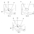
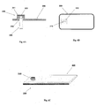
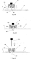
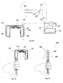
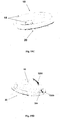
- Figures 1A-1C show connection of the patch unit (10) to and disconnection of the patch unit (10) from the needle unit (20).
- Figure 1A shows the needle unit (20) being attached to the body. In Fig. 1A are seen also, the cradle (300) and the well (310). After attaching the needle unit (20) to the body, the user may connect the patch unit (10) to the needle unit (20) by connecting the patch unit housing to the cradle and the exit port (not shown) of the patch unit to the well (310).
- Figure 1B shows the patch unit (10) and the needle unit (20) being connected and attached to the patient body. The patch unit (10) and needle unit (20) after connection together constitute a fluid delivery device.
- Figure 1C shows disconnection of the patch unit (10) from the needle unit (20). The process of connection and disconnection can be repeated many times according to the patient's discretion or as otherwise necessary.
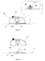
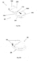
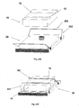
- Figures 2A-2E show schematically two units of the fluid delivery device, the patch unit (10) and the needle unit (20).
- Figure 2A shows the two units, the patch unit (10) and the needle unit (20).
- Figure 2B shows the needle unit (20) adhered to the skin (5).
- Figure 2C shows connection of the two units.
- Figure 2d shows the two connected units brought into operation mode, and Figure 2E shows disconnection of units. The two units can be repeatedly connected and disconnected.
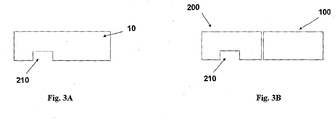
- FIGS 3A-3B show the patch unit (10) in more detail.
- the patch has on its lower surface an exit port (210).
- the patch unit (10) can be composed of a single part ( fig. 3A ) or of two parts ( fig. 3B ).
- the two part patch unit (10) is composed of a reusable part (100) and a disposable part (200) with an exit port (210).
- the exit port (210) allows fluid dripping during priming and fluid communication with the needle unit (20) during operation.
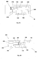
- FIGs 4A-4B show an embodiment of the patch unit (10) employing a peristaltic pump as a pumping mechanism for dispensing fluid to a patient body.
- Figure 4A shows a single-part patch unit (10). The fluid is delivered from a reservoir (220) provided in the patch unit (10) through a delivery tube (230) to the exit port (210).
- the peristaltic pump comprises a rotary tooth wheel (110) provided with rollers and a stator (290).
- Driving mechanism (120) is provided (e.g. a stepper motor, a DC motor, a SMA actuator or the like), which rotates the rotary wheel and is controlled by electronic components residing in the patch unit (10).
- electronic components can be controller, processor and/or transceiver.
- the electronic components are schematically designated by a common numeral (130).
- An appropriate energy supply means (240) is also provided, which may include one or more batteries.
- Infusion programming can be carried out by a remote controller (not shown) having a bidirectional communication link with the transceiver provided in the patch unit (10).
- the infusion programming can be carried out by manual buttons/switches (105) provided on the patch unit (10).
- Figure 4B shows a two-part patch unit (10) comprised of a reusable part (100) and a disposable part (200).
- Reusable part (100) may comprise positive displacement pump provided with rotary wheel (110), driving mechanism (120) and/or electronic components (130).
- Disposable part (200) may include a reservoir (220), delivery tube (230), energy supply means (240), exit port (210) and/or stator (290). Fluid dispensing is possible after connecting the reusable part (100) with disposable part (200). This arrangement is described in USSN 11/397,115 .
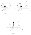
- Figures 5A-5C show the needle unit (20).
- Figure 5A shows the needle unit (20) before insertion.
- the needle unit (20) comprises the following components: a cradle (300), a cannula (330), a penetrating member (320) and a well (310).
- Fig 5B shows the needle unit (20) after it has been adhered to the skin (5).
- the cradle (300) is adhered to the skin (5) by virtue of adhesive layer, which is provided on the side of the cradle (300) that faces the skin (5).
- the cannula (330) and the penetrating member (320) are shown after they have been placed in the subcutaneous compartment of the patient's body.
- Fig 5C shows a still further step, when the needle unit (20) remains adhered to the skin (5) and the cannula (330) remains within the subcutaneous compartment while the penetrating member (320) is being removed.
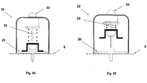
- FIGS 6A-6C show additional details of the needle unit (20): a cross sectional view (6A), an upper view (6B) and a perspective view (6C).
- the cradle (300) is configured as a flat and thin resilient sheet and it can be made for example from a polymer sheet having thickness of about 0.8 mm.
- the cradle (300) may be configured to any desired shape suitable for connection to the patch unit (10).
- To the bottom side of the cradle (300) that faces the skin (5) can be attached an adhesive tape (i.e. 3MTM Soft, conformable aperture non-woven cloth tape) or this bottom side can be coated with a biocompatible epoxy layer enabling adherence to the skin (5).
- adhesive tape i.e. 3MTM Soft, conformable aperture non-woven cloth tape
- a protrusion extends upwardly from the cradle (300) and forms the well (310).
- the well (310) may be positioned at the center, corner or any other location of the cradle (300).
- the upper end of the well (310) comprises a well inlet port (311), and the lower end of the well (310) comprises an outlet port (312) through which the cannula (330) is attached to the cradle (300).
- the inlet port (311) is sealed with a septum (313) that can be made of any self-sealable material (i.e. silicon rubber).
- the septum (313) can be pierced many times by a connecting lumen (250) provided in the patch unit (10) as will be described in greater detail below with reference to Figure 17 .
- the septum (313) keeps the well (310) sealed after withdrawal of the penetrating member (320) as shown in Figure 7 .
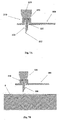
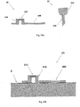
- Figures 7A-7D shows how the needle unit (20) is attached to the body of a patient.
- the attachment procedure includes insertion of the cannula (330) and subsequent adherence of the cradle (300) to the skin (5).
- Fig. 7A shows the needle unit (20) before attachment.
- the needle unit (20) includes cannula (330), cradle (300), well (310) and penetrating member (320).
- the penetrating member (320) includes a penetrating dagger (321) having a sharp tip (322) and a grip portion (323).
- the penetrating member (320) punctures the self-sealable septum (313) and displaces the cannula (330) towards the skin (5) while the sharp tip (322) pierces the skin (5) and the cannula (330) penetrates the subcutaneous compartment under the skin surface.
- Fig 7B shows the needle unit (20) before insertion, i.e. just before the penetrating member punctures the skin and the cannula penetrates the subcutaneous compartment.
- Fig. 7C shows the needle unit (20) after insertion.
- the cradle (300) is adhered to the skin (5) and the cannula (330) and penetrating member (320) are subcutaneously inserted.
- Fig. 7D shows the needle unit (20) adhered to the skin (5) and the penetrating member (320) removed from the needle unit (20). The well remains to be sealed by the septum (313) after penetrating member (320) withdrawal.
- the needle unit can be attached to the skin automatically by means of an inserter.
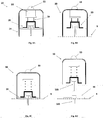
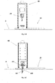
- Figures 8A-F show an automatic insertion of the needle unit (20) by using an inserter (30).
- the inserter (30) has a cup-shaped body.
- the inserter (30) comprises a cup-shaped body portion (31), an actuation mechanism (32) e.g. an actuator, an activation button/trigger (33) and a spring biased plunger element (34).
- the needle unit (20) is fully concealed within the inserter's body portion (31).
- Figure 8B shows how the inserter (30) is located on the skin (5) before insertion. By triggering the activation button/trigger (32) the needle unit (20) is fired towards the skin (5).
- Figure 8C shows the needle unit (20) being fired and attached to the skin upon triggering the activation button/trigger (33).
- Figure 8D shows withdrawal of the inserter (30), while leaving the needle unit (20) in place.
- Figures 8E-F show an alternative embodiment, in which penetrating member (320) is being automatically withdrawn from the needle unit (20).
- the inserter is provided with a retraction spring (35), which retracts the penetrating member (320).
- Figure 8e shows the needle unit (20) placement following button/trigger (33) depression.
- the retraction spring (35) is extended.
- Figure 8f shows penetrating member (320) withdrawal by the retracted spring (35), leaving the needle unit (20) in place.
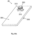
- Figures 9A-9B show another embodiment of the inserter.
- Figures 9A-9B show the cradle (300) provided with the well portion (310) protruding therefrom and sealed by a septum (313).
- the cradle (300) is provided with arcuate discrete slits (305) formed on the cradle's upper face and surrounding the well portion (310).
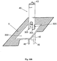
- FIG 10A shows the needle unit (20) comprising cradle (300) with the penetrating member (320) inserted within the well portion (310). Now, the needle unit (20) is ready for loading into inserter.
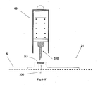
- FIG 10B is shown how the needle unit (20) is loaded into inserter (40). It is seen that the inserter is provided with legs (45) which are intended for entering into slits (305).
- Figure 10B shows the inserter with needle unit (20) loaded therein ready for firing towards the skin (5). By triggering the activation button/trigger (43) the needle unit (20) can be fired towards the skin (5).
- Figure 10C shows the needle unit (20) being fired and attached to the skin (5) upon triggering the activation button/trigger (43).
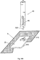
- Figure 10D shows automatic withdrawal of the inserter (40) including penetrating member (320), while leaving the needle unit (20) in place.
- cradle (300) is configured as a flat and thin resilient sheet having thickness of about 0.8 mm, it may be difficult to prevent crumpling of the cradle (300) and ensure a uniform horizontal spreading of the cradle surface, which is crucial for a reliable adherence of the cradle (300).
- Figure 10E shows an embodiment of the needle unit (20) provided with a few strips (47) which prevent crumpling (i.e., crumpling prevention means) of the cradle surface during firing of the needle unit (20). The strips (47) are connected by their one end to the grip portion (323) of the penetrating member (320).
- the strips (47) are slightly adhered to the cradle (300) by glue and are spread across the upper surface of the cradle (300). It is preferable if the strips (47) are located between adjacent arcuate slits (305). The width, thickness and rigidity of the strips (47) are selected to ensure that the cradle (300) remains in horizontal position during firing and does not crumple.
- Figure 10F shows the needle unit (20) provided with strips (47) and being loaded within the inserter (40). It is seen that legs (45) pass through slits (305). Strips (47) ensure spreading of the cradle (300) without crumpling.
- Figure 10G shows the next step in which the inserter (40) is withdrawn. The strips (47) disconnect from the cradle (300)and remain attached to the grip portion (323) when the inserter is evacuated from the cradle (300).
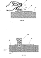
- Figs. 11A-11F show another embodiment of the needle unit.
- the needle unit comprises two parts as follows:
- Fig. 11A shows the two parts of the needle unit (20) before insertion - the penetrating cartridge part (22) and the cradle part (21).
- the cradle part (21) comprises the cradle base (300) and connecting latches (306), which are situated around an opening made in the cradle base (300).
- the penetrating cartridge part (22) comprises well portion (310), lateral recesses (316) made in the well portion, septum (313), cannula (330) and penetrating member (320).
- the amount of recesses and their location should allow snapping of the latches on the recesses when the penetrating cartridge part (22) approaches the cradle part (21).
- Fig 11B shows an upper view of the cradle part (21) including cradle base (300) and three connecting latches (306), which are situated symmetrically around the opening (307).
- Fig 11C shows the cradle part (21) attached to the patient skin (5). The attachment can be achieved by gluing with adhesives or by other means known in the art. It will be appreciated that an adhesive layer should be put on that side of the cradle base, which faces the skin.
- Figure 11D shows how the penetration cartridge part (21) is approaching the cradle part (21) and latches (306) are about to snappingly engage the recesses (316). Upon engagement the sharp tip (322) of the penetrating member pricks skin (5) and cannula (330) penetrates the body.
- Figure 11E shows the penetration cartridge part (22) connected to the cradle part (21).
- Figure 11F shows the removal of the penetrating member (320) from the penetrating cartridge part (22).
- the cradle part (21) remains adhered to the skin (5) and the cannula (330) remains in the body.
- the self-sealable septum (313) of the well portion (310) allows for repeated connection/disconnection of the connecting lumen of the patch unit (10) and prevents leaking and penetration by contaminants, as shown in Figure 17 .
- Figures 12A-12D show an embodiment of an inserter (50) for use with the two part needle unit (20).
- the inserter facilitates adhesion of the cradle part (21) to the skin (5) and allows automatic connection of penetrating cartridge part (22) with the base cradle part (21).
- the cradle base part (21) is first attached to the skin and consecutively cartridge part (22) is fired by the inserter (50) toward the cradle base part (21) so as to connect the cradle base part (21) with the penetrating cartridge part (22).
- Fig. 12A shows inserter (50) and the two part needle unit (20) that comprises cradle part (21) and penetrating cartridge part (22). The figure shows the situation before insertion.
- the inserter (50) is provided with an actuation mechanism (52) employing plunger-spring element (54) and actuation button/trigger (53).
- the inserter is loaded with penetrating cartridge part (22).
- the penetrating cartridge part (22) comprises well portion (310), cannula (330) and penetrating member (320).
- the cradle part (21) comprises cradle base (300) which upper side is relatively glued (or otherwise secured) to the inserter's bottom side.
- Figure 12B shows the cradle part (21) attached to the patient skin (5). The attachment can be done by adhesives or by other means known in the art. Adherence is ensured by pressing the inserter (50) toward the skin.
- Fig. 12C shows the inserter (50) after the actuation button/trigger (53) is pressed and the penetrating cartridge part has been fired. Upon firing the penetrating cartridge part (22) is connected to the cradle part (21) by virtue of snapping engagement between latches (306) and depressions (316) made on the well portion (310) of the penetrating cartridge part (22).
- Figure 12D shows still further step, when the inserter (50) along with the penetrating member (320) is being automatically removed from the skin (5).
- the cradle part (21) remains stay adhered to the skin (5) and the cannula (330) remains inserted within body.
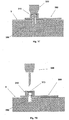
- Figs. 13A-13G show another embodiment of a needle unit (20) which is intended for manual insertion mode.
- the needle unit (20) also comprises two parts as follows:
- Fig. 13A shows the two parts before insertion.
- the cradle part (21) comprises cradle base (300) and well portion (310).
- the penetration cartridge part (22) comprises cannula (330), penetrating member (320) and septum (313).
- Figure 13B shows the cradle part (21) after it has been attached to the patient skin (5). The attachment can be done by adhesives or by other means known in the art.
- Figure 13C shows manual insertion of the penetration cartridge (22) through the well portion (310).
- the septum (313) is pierced by the dagger (321).
- Figure 13D shows sharp tip of the dagger (322) and the cannula (330) within the subcutaneous tissue.
- Figure 13E shows the removal of the penetrating member (320).
- the cradle part (21) remains adhered to the skin and the cannula (330) remains in the body.
- the self-sealable septum (313) of the well portion (310) prevents leaking of the therapeutic fluid as well as contamination.
- Fig. 13F shows another embodiment of the penetration cartridge part (22). In this embodiment the septum (313) is attached to the cannula (330) and is introduced into the upper side of the well portion (310) during insertion of the penetrating cartridge (22) through the well portion (310).
- Fig. 13G shows another embodiment of the cradle part (20). In this embodiment the well portion (310) is in a tilted position allowing the insertion of the penetrating cartridge part (22) at an angle with respect to the skin.
- FIGs 14A-14F show another embodiment of an inserter for use with a two part needle unit.
- the inserter (60) is used for the insertion of the cartridge part (22) into the cradle base part (21).
- the cradle part (21) is first manually attached to the skin (5) and consecutively the penetrating cartridge part (22) is automatically inserted by the inserter (60).
- Fig. 14A shows the inserter housing (60) and the penetrating cartridge part (22) before insertion.
- Figure 14B shows the cradle part (21).
- the inserter housing (60) accommodates actuation mechanism (62), spring-loaded plunger element (64) and the penetration cartridge part (22).
- the penetrating cartridge part (22) comprises cannula (330) and penetrating member (320).
- the cradle part (21) comprises cradle (300) and well portion (310).
- Figure 14C shows the cradle part (21) attached to the patient skin (5). The attachment can be done by adhesives or by other means known in the art.
- Figure 14D shows the inserter housing (60) put on the well portion (330) of the cradle part (21).
- Fig. 14E shows the penetrating cartridge (22) after penetrating the skin (5) such that the cannula (330) has penetrated within the subcutaneous tissue.
- Figure 14F shows the removal of the penetrating member (320).
- the cradle part (21) remains adhered to the skin (5) and the cannula (330) remains in the body.
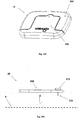
- FIG 15 shows still another embodiment of the patch unit (10) that is composed of a single part.
- the patch unit (10) contains housing (11), which is provided with exit port (210), through which protrudes a short connecting lumen (250) having sharpened forward end.
- the opposite rear end of the lumen is in fluid communication with the delivery tube (230) and reservoir (220).
- the sharpened end of the lumen (250) enters in the cannula (330) to provide fluid communication between the cannula (330) and reservoir (220).
- the connecting lumen (250) is rigidly secured within the exit port (210). It is connected by its rear end to the tube (230) through a connector (251).
- the housing (11) is provided with lateral notches (12).
- the sharpened forward end of the connecting lumen (250) pierces the septum (313) of the needle unit (20) and enters in the cannula (330).
- the lateral notches (12) allow connecting of the patch unit (10) to the needle unit (20).
- FIG 16 shows another embodiment of the patch unit (10) composed of two parts.
- a reusable part (100) contains components that can be used multiple times while disposable part (200) contains disposable components including reservoir (220) and exit port (210). The disposable components are used until emptying of the reservoir (220).
- the connecting element e.g., connecting lumen
- Lateral notches (12) are provided on exterior sides of both parts.
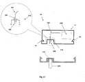
- FIGS 17A-17F show an example of connection and disconnection of the patch unit (10) and the needle unit (20).
- Fig. 17A shows the two units before connection.
- the needle unit (20) is attached to the user skin (5) and the cannula (330) penetrates within the subcutaneous tissue.
- the patch unit (10) in this example is composed of two parts and contains lateral notches (12), exit port (210) and connecting lumen (250).
- the needle unit (20) contains cradle (300), cannula (330), anchoring latches (302), well portion (310) and well septum (313). When the patch unit (10) is brought into contact with the needle unit (20) it is guided by the anchoring latches (302) maintaining precise alignment between the two units and anchoring of the two units.
- Figure 17B shows the patch unit (10) after is has been connected to the skin-adhered needle unit (20) and secured due to snapping engagement of the anchoring latches (302) provided at the outside periphery of the needle unit (20) with the lateral notches (12) provided at the patch unit (10).
- FIG. 17C shows the patch unit (10) being disconnected by back-pulling the elastically deformable latches (302).
- Figure 17d shows the patch unit (10) disconnected from the needle unit (20) which remains adhered to the skin (5) and the cannula (330) remains in the body.
- the self-sealable septum (313) prevents body fluids from leaking and also prevents contamination.
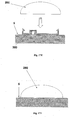
- the cradle (300) could be protected to avoid contamination and abrasion of protruding elements by a protective cover (280), as shown in figures 17E-17F .
- the protective cover (280) can be configured as a convex - shaped rigid polymeric cover which conceals the cradle (300) within. Thus, the cradle (300) when covered is not exposed to the environment. The protective cover (280) should be removed before reconnection of the patch unit (10).
- FIGs 18A-18K shows another embodiment of a fluid delivery device that includes a patch unit and a needle unit.
- the patch unit (10) comprises two parts - reusable part (100) and disposable part (200).
- the disposable part is provided with the exit port (210) which is located not in the center of the disposable part (200) but close to its lateral side.
- Figure 18A shows the two parts.
- the disposable part (200) has a U-shape configuration and the reusable part (100) has a squared configuration mating the recess in the U-shaped disposable part (200).
- the reusable part (100) is fitted with driving mechanism (110), with pumping mechanism (120) e.g. a peristaltic pump and with suitable electronics (130).
- the disposable part (200) is fitted with reservoir (220), with power supply means (240), with delivery tube (230) and with connecting lumen (250).
- the tube (230) is connected by its one end to the reservoir (220) and by its opposite end to the connecting lumen (250).
- the connecting lumen (250) resides within the exit port (210).
- FIG. 18B and 18C it is shown how reservoir (220) is being filled and priming is carried out.
- the filling and the priming are carried out by a syringe connectable to the reservoir (220).
- Connection of the syringe to the reservoir may be also carried out by means of a dedicated adapter, examples of which are described in more detail in commonly owned application USSN 60/838,660 .
- the adapter allows connection of the filling syringe to the reservoir (220).
- Figure 18D shows the patch unit (10) assembled after the reusable part (100) and the disposable part (200) are connected. Upon connection, air is purged out of the reservoir (220), out of the tube (230) and out of the connecting lumen (250).
- Figure 18E shows the reusable part (100) and the disposable part (200) before they are connected.
- Figure 18F shows another view of the patch unit (10) after connecting the two parts.
- Figure 18g shows the needle unit (20) before its adherence to the skin.
- the needle unit (20) comprises cradle (300), well portion (310) and cannula (330).
- Figure 18H shows the needle unit (20) after it has been adhered to skin (5).
- Figure 18I shows connection of patch unit (10) to needle unit (20);
- Figure 18J shows both units being connected (operation mode) and
- Figure 18K shows the units being disconnected.
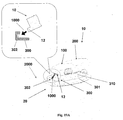
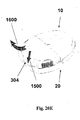
- FIGs 19A-19D show another embodiment of a fluid delivery device and a method for connecting a patch unit (10) and a needle unit (20).
- the patch unit (10) comprises a reusable part (100) and a disposable part (200).
- the needle unit (20) comprises a cradle (300) having an elevated peripheral wall (301), well portion (310) and adhesive layer at the lower surface of the cradle.
- Figure 19A shows the first step of connecting the patch unit (10) to the needle unit (20) by moving the patch unit (10) towards the needle unit (20) along arrow (1000), such that a protrusion (12) in the cradle (300) engages with a corresponding recess (302) provided on the rear end (2000) of the cradle (300) (or vice versa).
- Figure 19B shows the next step of connecting the two units by pivoting the front end (3000) of the patch unit (10) towards the needle unit (20) along arrow (1100).
- the connection is carried out by snapping engagement of a latch (304) in the cradle (300) with a corresponding notch (14) in the patch (10).
- Figure 19C shows the device in an operation mode after the patch (10) and the needle (20) units have been connected.
- the patient can conveniently use the device since connecting and disconnecting of the patch unit (10) and the needle unit (20) does not affect the use of the device.
- the patient can give an insulin bolus dose by pressing simultaneously the two buttons/switches (15) provided at the lateral walls of the reusable part (100).
- Figure 19D shows disconnection of the units by the release of a latch (304), pulled along the arrow (1300).
- the patch unit (10) now may be withdrawn by pivoting it along the arrow (1200).
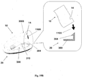
- FIGs 20A-20D shows another embodiment of a fluid delivery device and a method for connection the patch unit (10) and the needle unit (20).
- the patch unit (10) comprises a reusable part (100) and a disposable part (200). There is provided an exit port (210) in the disposable part (200).
- the needle unit (20) comprises a cradle (300) having an elevated side wall (301), a well portion (310) and adhesive layer at the lower surface of the cradle.
- Figure 20A shows patch unit (10) and needle unit (20) being connected by a sliding movement of the patch unit (10) towards the cradle (300) along arrow (1400).
- Figure 20B shows operation mode of the device after the patch unit (10) has been connected to the needle unit (20).
- Patient can control insulin bolus dose by using the remote controller or by pressing simultaneously on the two buttons/switches (15).
- Figure 20C shows the connection of the exit port (210) with well portion (310) therefrom introducing the connecting lumen (250) into the well portion (310).
- Connection by sliding requires horizontally directed connecting lumen (250) on the patch unit (10) and a lateral inlet port (311) on the well portion (310).
- the self-sealable septum (313) is provided for the penetrating member insertion. This septum (313) seals the well portion (310) and it is oriented horizontally.
- an additional self-sealable septum (315) which is directed vertically. This septum is provided for penetrating of the connecting lumen (250).
- Figure 20D shows the connecting lumen (250) which pierces the well's septum (313) allowing fluid communication with the reservoir.
- Figure 20E shows disconnection of patch unit (10) from needle unit (20) by releasing the latch (304) along arrow (1500) followed by the sliding withdrawal of the patch unit (10) along arrow (1600).
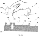
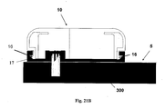
- FIGS 21A-21C show another embodiment of a fluid delivery device and a method for connecting a patch unit (10) and a needle unit (20).
- the patch unit (10) comprises a reusable part (100) and a disposable part (200).
- the patch unit (10) is provided with elastically deformable latches (16) provided at the periphery of the patch unit (10).
- the needle unit (20) comprises a cradle (300) and a well portion (310).
- Notches (17) are provided at the periphery of the cradle (300).
- the notches (17) are configured to mate the latches (16), such that snapping engagement is possible therebetween.
- the peripheral wall (2100) of the patch unit (10) is elastically deformable, such that latches (16) can be easily pressed inwardly.
- Figure 21A shows the two units are being brought together and are about to be connected by virtue of snapping engagement of latches (16) with notches (17).
- Fig. 21B shows patch unit (10) secured on the cradle (300) by virtue of snapping of the latches (16) on notches (17).
- Fig 21C shows disconnection of patch unit (10) by squeezing the wall of the patch unit (10) such that latches (16) are elastically displaced inwardly to allow their disengagement from the notches (17).
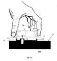
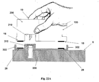
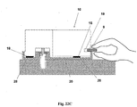
- FIGs 22A-22C show another embodiment of a fluid delivery device and of a method for connecting a patch unit (10) and a needle unit (20).
- the patch unit (10) and the needle unit (20) are connectable by virtue of magnetic forces.
- the patch unit (10) comprises a reusable part (100) and a disposable part (200).
- the needle unit (20) comprises a cradle (300) and a well portion (310).
- Fig. 22A shows patch unit (10) being brought to the needle unit so as to connect it to the needle unit (20).
- Magnetic strips (18) are provided at several locations of the bottom surface of the patch unit (10).
- Magnetic strips (28) are provided at corresponding locations of the upper side of the cradle (300).
- Cradle (300) is configured with supporting walls (302) protruding upwardly and parallel to the outside surface of the well portion (310).
- the exit port (210) of the patch unit (10) is configured to match the periphery of the wall portion (310).
- Figure 22B shows that connection between the two parts is maintained by magnetic attraction forces of the magnetic strips (18) and (28).
- Fig. 22C shows disconnection of patch (10) from needle unit (20). This may be affected by placing a thin separating means (9) such as a coin or pin within a dedicated recess (19) provided at the patch unit (10).
- connection may be achieved by using any other suitable connective material instead of magnetic strips, such as Velcro® Adhesives (e.g., comprising hooks and loops), or the like.
- FIGS 23A-23E show another embodiment of a fluid delivery device and of a method for connecting a patch unit (10) and a needle unit (20).
- the patch unit (10) is securable on the needle unit (20) by virtue of a trap-like mechanism (an example of which is described below), which, according to some embodiments, is (for example) a structure utilizing one or more catches/recesses/grooves to receive corresponding swing arms (arms) -- at least a portion of the swing arm is captured by a corresponding groove thereby "trapping" the patch within the cradle.
- the patch unit (10) comprises a reusable part (100) and a disposable part (200).
- the needle unit (20) comprises a cradle (300) and a well portion (310). Swiveling arms (302) terminated by hooked ends (303) are provided on the needle unit (20) and corresponding grooves (12) are provided on the patch unit (10).
- Figure 23A shows connection of patch unit (10) and needle unit (20) by arms (302).
- Figure 23B shows patch unit (10) being secured by arms (302) which have been swiveled so as the hooked ends (303) have entered within the grooves (12, 303) in order to lock the patch unit on the cradle.
- Fig. 23C shows disconnection of patch (10) by swiveling the arms (302) until the hooked ends (303) exit the grooves (12) and release the patch unit (10).
- Figures 23D shows perspective view of the patch unit (10) being released and disconnected from the cradle.
- Figure 23E shows perspective view of the patch unit (10) secured on the cradle (300).
Claims (13)
- Infusionssystem für therapeutisches Fluid für die Zufuhr eines therapeutischen Fluids an einen menschlichen Körper, wobei das System folgendes umfasst:eine erste Einheit (20), umfassend:ein Gestell (300), das für zur Adhäsion an eine kutane Region des menschlichen Körpers gestaltet ist;eine Kanüle (330); undein selbstverschließbares Septum (313), wobei ein distaler Teil der Kanüle (330) für eine subkutane Platzierung in dem menschlichen Körper gestaltet ist, und wobei das selbstverschließbare Septum (313) einen proximalen Teil der Kanüle (330) von einer äußeren Umgebung trennt; undeine zweite Einheit (10), die für eine entfernbare Befestigung an der ersten Einheit (20) gestaltet ist, wobei die zweite Einheit (10) folgendes umfasst:eine Pumpe (120);einen Speicher (220) zum Speichern eines therapeutischen Fluids; undein Verbindungslumen (250), das so gestaltet ist, dass es das selbstverschließbare Septum (313) penetriert, um die zweite Einheit (10) in Fluidkommunikation mit der ersten Einheit (20) zu bringen;dadurch gekennzeichnet, dass die erste und die zweite Einheit (10, 20) durch eine relative Drehbewegung zwischen den Einheiten (10, 20) verbunden werden können.
- System nach Anspruch 1, ferner eines der folgenden umfassend: mindestens einen Magneten (18, 28) zur entfernbaren Befestigung der zweiten Einheit (10) an der ersten Einheit (20); einen fallenartigen Mechanismus (302, 303) zur entfernbaren Befestigung der zweiten Einheit (10) an der ersten Einheit (20); einen Klettverschluss zur entfernbaren Befestigung der zweiten Einheit (10) an der ersten Einheit (20); und einen Klebstoff zur entfernbaren Befestigung der zweiten Einheit (10) an der ersten Einheit (20).
- System nach Anspruch 1, wobei die Kanüle (330) und das selbstverschließbare Septum (313) sich wenigstens teilweise in einem Schacht (310) befinden.
- System nach Anspruch 3, wobei das Gestell (300) integral wenigstens mit der Kanüle (330) oder dem Schacht (310) ist.
- System nach Anspruch 1, wobei das Gestell (300) und der Schacht (310) für eine zusammenpassende Anbringung durch wenigstens einen Verschluss (306) gestaltet sind.
- System nach Anspruch 1, wobei die erste Einheit (20) ferner ein penetrierendes Element (320) umfasst, das für eine Platzierung durch die Kanüle (330) während der Adhäsion der ersten Einheit (20) an der kutanen Region und der subkutanen Platzierung der Kanüle gestaltet ist, sowie für die Entfernung der Kanüle (330) nach der subkutanen Platzierung und Adhäsion.
- System nach Anspruch 1, wobei die erste Einheit (20) für eine Anbringung an einer Insertervorrichtung (30) zur Verwendung bei der Anbringung der ersten Einheit (20) an dem menschlichen Körper gestaltet ist.
- System nach Anspruch 1, wobei die zweite Einheit (10) folgendes umfasst:einen Einwegteil (200), der den Speicher (220) und das Verbindungslumen (250) umfasst; undeinen wiederverwendbaren Teil (100), der die Pumpe (120) umfasst.
- System nach Anspruch 1, ferner umfassend einen Verbindungsbereich (302) an der ersten Einheit (20) zur entfernbaren Verbindung mit einem entsprechenden Verbindungsbereich (12) an der zweiten Einheit (10) zur entfernbaren Verbindung der zweiten Einheit (10) mit der ersten Einheit (20).
- System nach Anspruch 1, wobei bei Verbindung der ersten und der zweiten Einheit (20, 10) das Verbindungslumen (250) der zweiten Einheit (10) das selbstverschließbare Septum (313) der ersten Einheit (20) einsticht.
- System nach Anspruch 10, wobei das Einstechen des selbstverschließbaren Septums (313) durch das Verbindungslumen (250) vertikal, horizontal oder in einem Winkel erfolgt.
- System nach Anspruch 1, ferner umfassend ein Antiknautschmittel (47) des Gestells (300) während der Einführung einer penetrierenden Einheit (310, 320) durch eine Öffnung (307).
- System nach Anspruch 1, ferner umfassend eine entfernbare Abdeckung (280) für die erste Einheit (20) zur Abdeckung wenigstens eines Teils des Gestells (300) mit dem selbstverschließenden Septum (313), wobei die Abdeckung (280) im Wesentlichen den wenigstens einen Teil des Gestells (300) zu der äußeren Umgebung abdichtet, während die zweite Einheit (10) nicht mit dem Gestell (300) verbunden ist.
Priority Applications (7)
| Application Number | Priority Date | Filing Date | Title |
|---|---|---|---|
| PL18163685T PL3400979T3 (pl) | 2006-12-22 | 2007-12-20 | Systemy i urządzenia do długotrwałego dostarczania płynu terapeutycznego |
| PL07849604T PL2125077T3 (pl) | 2006-12-22 | 2007-12-20 | Układy i urządzenia do przedłużonego doprowadzania płynu leczniczego |
| EP19206870.8A EP3632488B1 (de) | 2006-12-22 | 2007-12-20 | System zur nachhaltigen verabreichung einer therapeutischen flüssigkeit |
| SI200732026T SI2125077T1 (en) | 2006-12-22 | 2007-12-20 | SYSTEMS AND DEVICES FOR PERMANENT SUPPLY OF THERAPEUTIC FLUID |
| DK18163685.3T DK3400979T3 (da) | 2006-12-22 | 2007-12-20 | Systemer og anordninger til vedvarende indgivelse af en terapeutisk fluid |
| EP21211809.5A EP3998095B1 (de) | 2006-12-22 | 2007-12-20 | Vorrichtung zur verzögerten abgabe eines therapeutischen fluids |
| EP18163685.3A EP3400979B1 (de) | 2006-12-22 | 2007-12-20 | Systeme und vorrichtungen zur nachhaltigen verabreichung einer therapeutischen flüssigkeit |
Applications Claiming Priority (2)
| Application Number | Priority Date | Filing Date | Title |
|---|---|---|---|
| US87667906P | 2006-12-22 | 2006-12-22 | |
| PCT/IL2007/001578 WO2008078318A2 (en) | 2006-12-22 | 2007-12-20 | Systems and devices for sustained delivery of therapeutic fluid |
Related Child Applications (3)
| Application Number | Title | Priority Date | Filing Date |
|---|---|---|---|
| EP21211809.5A Division EP3998095B1 (de) | 2006-12-22 | 2007-12-20 | Vorrichtung zur verzögerten abgabe eines therapeutischen fluids |
| EP19206870.8A Division EP3632488B1 (de) | 2006-12-22 | 2007-12-20 | System zur nachhaltigen verabreichung einer therapeutischen flüssigkeit |
| EP18163685.3A Division EP3400979B1 (de) | 2006-12-22 | 2007-12-20 | Systeme und vorrichtungen zur nachhaltigen verabreichung einer therapeutischen flüssigkeit |
Publications (2)
| Publication Number | Publication Date |
|---|---|
| EP2125077A2 EP2125077A2 (de) | 2009-12-02 |
| EP2125077B1 true EP2125077B1 (de) | 2018-04-18 |
Family
ID=39185937
Family Applications (4)
| Application Number | Title | Priority Date | Filing Date |
|---|---|---|---|
| EP18163685.3A Revoked EP3400979B1 (de) | 2006-12-22 | 2007-12-20 | Systeme und vorrichtungen zur nachhaltigen verabreichung einer therapeutischen flüssigkeit |
| EP21211809.5A Active EP3998095B1 (de) | 2006-12-22 | 2007-12-20 | Vorrichtung zur verzögerten abgabe eines therapeutischen fluids |
| EP19206870.8A Active EP3632488B1 (de) | 2006-12-22 | 2007-12-20 | System zur nachhaltigen verabreichung einer therapeutischen flüssigkeit |
| EP07849604.9A Active EP2125077B1 (de) | 2006-12-22 | 2007-12-20 | Systeme und vorrichtungen zur verzögerten abgabe einer therapeutischen flüssigkeit |
Family Applications Before (3)
| Application Number | Title | Priority Date | Filing Date |
|---|---|---|---|
| EP18163685.3A Revoked EP3400979B1 (de) | 2006-12-22 | 2007-12-20 | Systeme und vorrichtungen zur nachhaltigen verabreichung einer therapeutischen flüssigkeit |
| EP21211809.5A Active EP3998095B1 (de) | 2006-12-22 | 2007-12-20 | Vorrichtung zur verzögerten abgabe eines therapeutischen fluids |
| EP19206870.8A Active EP3632488B1 (de) | 2006-12-22 | 2007-12-20 | System zur nachhaltigen verabreichung einer therapeutischen flüssigkeit |
Country Status (15)
| Country | Link |
|---|---|
| US (3) | US9662440B2 (de) |
| EP (4) | EP3400979B1 (de) |
| JP (1) | JP2011507555A (de) |
| CN (3) | CN101573151A (de) |
| AU (1) | AU2007337684A1 (de) |
| DK (4) | DK3632488T3 (de) |
| ES (3) | ES2670443T3 (de) |
| FI (2) | FI3632488T3 (de) |
| HK (1) | HK1220928A1 (de) |
| HU (1) | HUE061916T2 (de) |
| LT (1) | LT3632488T (de) |
| PL (3) | PL3632488T3 (de) |
| PT (1) | PT3632488T (de) |
| SI (3) | SI3400979T1 (de) |
| WO (1) | WO2008078318A2 (de) |
Families Citing this family (174)
| Publication number | Priority date | Publication date | Assignee | Title |
|---|---|---|---|---|
| PT1762259E (pt) | 2005-09-12 | 2010-12-10 | Unomedical As | Insersor para um conjunto de infusão com uma primeira e uma segunda unidades de mola |
| US8475408B2 (en) | 2005-11-08 | 2013-07-02 | Asante Solutions, Inc. | Infusion pump system |
| EP2338547B1 (de) * | 2006-02-09 | 2013-04-17 | DEKA Products Limited Partnership | Fluidzufuhrsysteme |
| ES2831604T3 (es) * | 2006-07-07 | 2021-06-09 | Hoffmann La Roche | Dispositivo de administración de fluidos y procedimientos de funcionamiento del mismo |
| US7789857B2 (en) * | 2006-08-23 | 2010-09-07 | Medtronic Minimed, Inc. | Infusion medium delivery system, device and method with needle inserter and needle inserter device and method |
| AU2007337685A1 (en) * | 2006-12-22 | 2008-07-03 | F.Hoffmann-La Roche Ag | Fluid delivery with in vivo electrochemical analyte sensing |
| SI3400979T1 (sl) | 2006-12-22 | 2020-02-28 | Roche Diabetes Care Gmbh | Sistemi in naprave za dolgotrajno aplikacijo terapevtske tekočine |
| EP2121076B1 (de) * | 2006-12-29 | 2017-04-05 | F. Hoffmann-La Roche AG | Extrakorporal tragbare infusionsvorrichtung |
| WO2008114254A1 (en) * | 2007-03-19 | 2008-09-25 | Medingo Ltd. | User interface for selecting bolus doses in a drug delivery device |
| WO2008122983A1 (en) * | 2007-04-10 | 2008-10-16 | Medingo Ltd. | Apparatus for pumping fluid |
| EP2152148A2 (de) * | 2007-05-07 | 2010-02-17 | Medingo Ltd. | Kolbenausgabe von flüssigkeiten in den körper mit analytkonzentrationsüberwachung |
| EP2155295A2 (de) * | 2007-05-11 | 2010-02-24 | Medingo Ltd. | Modulare medizinische flüssigkeitsabgabe-vorrichtung vom hautpflastertyp |
| WO2008152623A1 (en) * | 2007-06-11 | 2008-12-18 | Medingo Ltd. | Portable infusion device with reduced level of operational noise |
| WO2009013637A2 (en) * | 2007-06-20 | 2009-01-29 | Medingo Headquarters | Method and device for assessing carbohydrate-to-insulin ratio |
| WO2009002455A1 (en) | 2007-06-21 | 2008-12-31 | Medingo Headquarters | Method and device for preventing hypoglycemia |
| WO2009001337A2 (en) * | 2007-06-22 | 2008-12-31 | Medingo Ltd. | Communications for medicinal fluid delivery system |
| US8002752B2 (en) * | 2007-06-25 | 2011-08-23 | Medingo, Ltd. | Protector apparatus |
| US9244077B2 (en) * | 2007-06-25 | 2016-01-26 | Roche Diabetes Care, Inc. | Method system and device for assessing insulin sensitivity |
| DK2173407T3 (da) * | 2007-07-02 | 2020-04-27 | Hoffmann La Roche | Anordning til indgivelse af lægemiddel |
| WO2009007970A1 (en) * | 2007-07-12 | 2009-01-15 | Medingo Ltd. | Systems and methods for glycemic control during pump disconnection |
| WO2009013734A2 (en) * | 2007-07-20 | 2009-01-29 | Medingo Ltd. | Energy supply for fluid dispensing device |
| WO2009016637A2 (en) * | 2007-08-01 | 2009-02-05 | Medingo Ltd. | A device for drug delivery |
| JP2010535058A (ja) * | 2007-08-01 | 2010-11-18 | メディンゴ・リミテッド | 治療用流体の注入を促進し且つ身体分析物を検出するための装置 |
| DK2185218T3 (da) | 2007-08-01 | 2013-09-30 | Medingo Ltd | Aftagelig bærbar infusionsanordning |
| CN101808680B (zh) | 2007-08-01 | 2014-07-02 | F·霍夫曼-拉罗氏股份公司 | 带有用于监测和控制流体输送的器件的便携式输注设备 |
| AU2008302516B2 (en) | 2007-09-17 | 2013-09-19 | Tecpharma Licensing Ag | Insertion devices for infusion devices |
| WO2009044401A2 (en) | 2007-10-02 | 2009-04-09 | Yossi Gross | External drug pump |
| US9345836B2 (en) | 2007-10-02 | 2016-05-24 | Medimop Medical Projects Ltd. | Disengagement resistant telescoping assembly and unidirectional method of assembly for such |
| US10420880B2 (en) | 2007-10-02 | 2019-09-24 | West Pharma. Services IL, Ltd. | Key for securing components of a drug delivery system during assembly and/or transport and methods of using same |
| US9656019B2 (en) | 2007-10-02 | 2017-05-23 | Medimop Medical Projects Ltd. | Apparatuses for securing components of a drug delivery system during transport and methods of using same |
| US7967795B1 (en) | 2010-01-19 | 2011-06-28 | Lamodel Ltd. | Cartridge interface assembly with driving plunger |
| US20100268043A1 (en) * | 2007-11-07 | 2010-10-21 | Ofer Yodfat | Device and Method for Preventing Diabetic Complications |
| WO2009060433A1 (en) * | 2007-11-09 | 2009-05-14 | Medingo Ltd. | Assessing residual insulin time |
| AU2008327483A1 (en) * | 2007-11-21 | 2009-05-28 | Medingo Ltd. | Analyte monitoring and fluid dispensing system |
| DE102007055636A1 (de) * | 2007-11-21 | 2009-05-28 | Robert Bosch Gmbh | Medikamenten-Dosiervorrichtung zum Verabreichen eines flüssigen Medikaments |
| EP2230996A1 (de) * | 2007-12-21 | 2010-09-29 | Medingo Ltd. | Vorrichtungen und verfahren zum antreiben einer medizinischen vorrichtung |
| US9199031B2 (en) * | 2007-12-26 | 2015-12-01 | Ofer Yodfat | Maintaining glycemic control during exercise |
| US20100280499A1 (en) * | 2007-12-26 | 2010-11-04 | Ofer Yodfat | System and method for glycemic control |
| US10188787B2 (en) | 2007-12-31 | 2019-01-29 | Deka Products Limited Partnership | Apparatus, system and method for fluid delivery |
| US8414563B2 (en) | 2007-12-31 | 2013-04-09 | Deka Products Limited Partnership | Pump assembly with switch |
| US8881774B2 (en) | 2007-12-31 | 2014-11-11 | Deka Research & Development Corp. | Apparatus, system and method for fluid delivery |
| US8900188B2 (en) | 2007-12-31 | 2014-12-02 | Deka Products Limited Partnership | Split ring resonator antenna adapted for use in wirelessly controlled medical device |
| US9456955B2 (en) | 2007-12-31 | 2016-10-04 | Deka Products Limited Partnership | Apparatus, system and method for fluid delivery |
| US10080704B2 (en) | 2007-12-31 | 2018-09-25 | Deka Products Limited Partnership | Apparatus, system and method for fluid delivery |
| US11357910B2 (en) * | 2007-12-31 | 2022-06-14 | Deka Products Limited Partnership | Pump assembly with switch |
| US8845613B2 (en) | 2008-01-28 | 2014-09-30 | Roche Diagnostics Operations, Inc. | Bolus dose determination for a therapeutic fluid dispensing system |
| US8641672B2 (en) | 2008-03-10 | 2014-02-04 | Roche Diagnostics Operations Inc. | Infusion and sensing device with battery charging and data transferring mechanisms |
| US9446185B2 (en) * | 2008-03-12 | 2016-09-20 | Roche Diabetes Care, Inc. | Devices and methods for improving accuracy of fluid delivery |
| CN103127573B (zh) | 2008-04-09 | 2015-03-25 | F·霍夫曼-拉罗氏股份公司 | 用于治疗流体输送的可粘着于皮肤的模块化系统 |
| JP2011518634A (ja) | 2008-04-29 | 2011-06-30 | メディンゴ・リミテッド | 薬物送達装置においてボーラス投与量及びボーラス送達パターンを選択するための方法 |
| EP2297662B1 (de) * | 2008-04-29 | 2019-08-07 | Roche Diabetes Care GmbH | Verfahren und vorrichtungen zur bolus-dosis und -verabreichungsauswahl in einer arzneimittelabgabevorrichtung |
| US20110071765A1 (en) * | 2008-05-16 | 2011-03-24 | Ofer Yodfat | Device and Method for Alleviating Postprandial Hyperglycemia |
| WO2009144726A1 (en) | 2008-05-29 | 2009-12-03 | Medingo Ltd. | A device, a system and a method for identification/authentication of parts of a medical device |
| US7959598B2 (en) | 2008-08-20 | 2011-06-14 | Asante Solutions, Inc. | Infusion pump systems and methods |
| JP5298699B2 (ja) * | 2008-08-20 | 2013-09-25 | セイコーエプソン株式会社 | 制御ユニット、チューブユニット、マイクロポンプ |
| EP2328636B1 (de) * | 2008-08-28 | 2013-06-12 | Medingo Ltd. | Vorrichtung zur verbesserung der subkutanen insulinabsorption |
| WO2010026580A2 (en) | 2008-09-05 | 2010-03-11 | Medingo Ltd. | Auditory notification device |
| EP2350894B1 (de) * | 2008-09-11 | 2019-07-03 | Roche Diabetes Care GmbH | Verfahren und einrichtungen zum zurechtschneiden eines bolus-verabreichungsmusters |
| US9393369B2 (en) | 2008-09-15 | 2016-07-19 | Medimop Medical Projects Ltd. | Stabilized pen injector |
| JP5282508B2 (ja) | 2008-09-29 | 2013-09-04 | セイコーエプソン株式会社 | 制御ユニット、チューブユニット、マイクロポンプ |
| WO2010041260A1 (en) | 2008-10-07 | 2010-04-15 | Medingo Ltd. | Skin securable drug delivery device with a shock absorbing protective shield |
| WO2010041261A1 (en) * | 2008-10-09 | 2010-04-15 | Medingo Ltd. | Skin securable drug delivery device with a shock absorbing protective shield |
| WO2010044088A1 (en) | 2008-10-16 | 2010-04-22 | Medingo Ltd. | Method and system for adaptive communication transmission |
| US8728034B2 (en) | 2008-11-11 | 2014-05-20 | Roche Diagnostics Operations Inc. | Modular fluid delivery device with quick-release / connect mechanism for drive screw |
| JP5195368B2 (ja) | 2008-12-05 | 2013-05-08 | セイコーエプソン株式会社 | チューブユニット、制御ユニット、マイクロポンプ |
| EP2201968A1 (de) | 2008-12-24 | 2010-06-30 | Roche Diagnostics GmbH | Insertionssystem und Insertionsvorrichtung |
| DK2391408T3 (en) | 2008-12-31 | 2018-02-05 | Hoffmann La Roche | PORTABLE MEDICAL FLUID ADMINISTRATION WITH DRIVE SCREW LED CONNECTOR WITH CONTAINER STAMP |
| AU2010231527A1 (en) * | 2009-03-30 | 2011-11-03 | F.Hoffmann-La Roche Ag | Devices and methods for enhancing drug absorption rate |
| WO2010132835A1 (en) * | 2009-05-15 | 2010-11-18 | Arstasis, Inc. | Devices, methods and kits for forming tracts in tissue |
| AU2010255324A1 (en) | 2009-06-04 | 2012-01-19 | F.Hoffmann-La Roche Ag | Device and method for adjusting basal delivery profile |
| WO2010146579A1 (en) | 2009-06-14 | 2010-12-23 | Medingo Ltd. | Devices and methods for malfunctions recognition in a therapeutic dispensing device |
| WO2011007356A1 (en) | 2009-07-16 | 2011-01-20 | Medingo Ltd. | Systems, methods and devices for accurate infusion of fluids |
| US8672873B2 (en) | 2009-08-18 | 2014-03-18 | Cequr Sa | Medicine delivery device having detachable pressure sensing unit |
| US8547239B2 (en) | 2009-08-18 | 2013-10-01 | Cequr Sa | Methods for detecting failure states in a medicine delivery device |
| US8882710B2 (en) | 2009-09-02 | 2014-11-11 | Medtronic Minimed, Inc. | Insertion device systems and methods |
| US8900190B2 (en) | 2009-09-02 | 2014-12-02 | Medtronic Minimed, Inc. | Insertion device systems and methods |
| US8157769B2 (en) | 2009-09-15 | 2012-04-17 | Medimop Medical Projects Ltd. | Cartridge insertion assembly for drug delivery system |
| US10071196B2 (en) | 2012-05-15 | 2018-09-11 | West Pharma. Services IL, Ltd. | Method for selectively powering a battery-operated drug-delivery device and device therefor |
| USD810279S1 (en) | 2009-09-15 | 2018-02-13 | Medimop Medical Projects Ltd. | Injector device |
| US10071198B2 (en) | 2012-11-02 | 2018-09-11 | West Pharma. Servicees IL, Ltd. | Adhesive structure for medical device |
| AU2010310941A1 (en) | 2009-10-30 | 2012-05-17 | F.Hoffmann-La Roche Ag | Systems, methods and devices for adjusting the insertion depth of a cannula associated with a portable therapeutic device |
| ATE553800T1 (de) | 2009-11-26 | 2012-05-15 | Hoffmann La Roche | Extern auslösbare kanülenanordnung |
| EP2506914B1 (de) | 2009-11-30 | 2018-10-17 | Roche Diabetes Care GmbH | Analytüberwachungs- und flüssigkeitsausgabesystem |
| US8998840B2 (en) | 2009-12-30 | 2015-04-07 | Medtronic Minimed, Inc. | Connection and alignment systems and methods |
| US8998858B2 (en) | 2009-12-29 | 2015-04-07 | Medtronic Minimed, Inc. | Alignment and connection systems and methods |
| US8858500B2 (en) | 2009-12-30 | 2014-10-14 | Medtronic Minimed, Inc. | Engagement and sensing systems and methods |
| US9039653B2 (en) | 2009-12-29 | 2015-05-26 | Medtronic Minimed, Inc. | Retention systems and methods |
| US9421321B2 (en) | 2009-12-30 | 2016-08-23 | Medtronic Minimed, Inc. | Connection and alignment systems and methods |
| US20120215163A1 (en) | 2009-12-30 | 2012-08-23 | Medtronic Minimed, Inc. | Sensing systems and methods |
| US8435209B2 (en) | 2009-12-30 | 2013-05-07 | Medtronic Minimed, Inc. | Connection and alignment detection systems and methods |
| US11497850B2 (en) | 2009-12-30 | 2022-11-15 | Medtronic Minimed, Inc. | Connection and alignment detection systems and methods |
| US8348898B2 (en) | 2010-01-19 | 2013-01-08 | Medimop Medical Projects Ltd. | Automatic needle for drug pump |
| JP5671824B2 (ja) * | 2010-03-25 | 2015-02-18 | セイコーエプソン株式会社 | 流体注入システム |
| BR112012024635A2 (pt) | 2010-03-30 | 2017-08-08 | Unomedical As | dispositivo médico |
| WO2011141907A1 (en) | 2010-05-10 | 2011-11-17 | Medimop Medical Projects Ltd. | Low volume accurate injector |
| US9216249B2 (en) | 2010-09-24 | 2015-12-22 | Perqflo, Llc | Infusion pumps |
| US9308320B2 (en) | 2010-09-24 | 2016-04-12 | Perqflo, Llc | Infusion pumps |
| US8915879B2 (en) | 2010-09-24 | 2014-12-23 | Perqflo, Llc | Infusion pumps |
| US9498573B2 (en) | 2010-09-24 | 2016-11-22 | Perqflo, Llc | Infusion pumps |
| WO2012059209A1 (en) | 2010-11-01 | 2012-05-10 | Roche Diagnostics Gmbh | Fluid dispensing device with a flow detector |
| US8905972B2 (en) | 2010-11-20 | 2014-12-09 | Perqflo, Llc | Infusion pumps |
| JP5917565B2 (ja) * | 2011-01-27 | 2016-05-18 | メドトロニック ミニメド インコーポレイテッド | 挿入デバイスシステムおよび方法 |
| WO2012123274A1 (en) | 2011-03-14 | 2012-09-20 | Unomedical A/S | Inserter system with transport protection |
| USD702834S1 (en) | 2011-03-22 | 2014-04-15 | Medimop Medical Projects Ltd. | Cartridge for use in injection device |
| EP2763723B1 (de) | 2011-10-05 | 2016-04-13 | Unomedical A/S | Inserter zum gleichzeitigen einsetzen mehrerer transkutaner teile |
| CA2851521C (en) | 2011-10-14 | 2020-09-22 | Amgen Inc. | Injector and method of assembly |
| EP2583715A1 (de) | 2011-10-19 | 2013-04-24 | Unomedical A/S | Infusionsschlauchsystem und Herstellungsverfahren |
| CA2866843C (en) | 2012-03-12 | 2020-04-21 | Unitract Syringe Pty Ltd | Fill-finish cartridges for sterile fluid pathway assemblies and drug delivery devices incorporating fill-finish cartridges |
| US9072827B2 (en) | 2012-03-26 | 2015-07-07 | Medimop Medical Projects Ltd. | Fail safe point protector for needle safety flap |
| EP2650031A1 (de) * | 2012-04-11 | 2013-10-16 | PharmaSens AG | Durch manuellen Druck aktivierter Anwendungsmechanismus |
| US20130317438A1 (en) | 2012-05-25 | 2013-11-28 | Arstasis, Inc. | Vascular access configuration |
| JP2015529501A (ja) * | 2012-08-20 | 2015-10-08 | エフ ホフマン−ラ ロッシュ アクチェン ゲゼルシャフト | 注入セット用アダプターを有する治療システム |
| US9731069B2 (en) | 2012-09-27 | 2017-08-15 | Becton, Dickinson And Company | Perpendicular infusion set and disposable inserter |
| US9421323B2 (en) | 2013-01-03 | 2016-08-23 | Medimop Medical Projects Ltd. | Door and doorstop for portable one use drug delivery apparatus |
| JP6098250B2 (ja) * | 2013-03-14 | 2017-03-22 | セイコーエプソン株式会社 | 液体輸送装置 |
| AU2014238267B2 (en) | 2013-03-22 | 2019-08-15 | Amgen Inc. | Injector and method of assembly |
| US9011164B2 (en) | 2013-04-30 | 2015-04-21 | Medimop Medical Projects Ltd. | Clip contact for easy installation of printed circuit board PCB |
| US9561324B2 (en) | 2013-07-19 | 2017-02-07 | Bigfoot Biomedical, Inc. | Infusion pump system and method |
| CA2920894C (en) | 2013-10-24 | 2023-03-14 | Amgen Inc. | Injector and method of assembly |
| US10569015B2 (en) | 2013-12-02 | 2020-02-25 | Bigfoot Biomedical, Inc. | Infusion pump system and method |
| JP2015167709A (ja) | 2014-03-07 | 2015-09-28 | セイコーエプソン株式会社 | 液体輸送装置及びポンプユニット |
| US10279106B1 (en) | 2014-05-08 | 2019-05-07 | Tandem Diabetes Care, Inc. | Insulin patch pump |
| CN106659845A (zh) | 2014-05-20 | 2017-05-10 | 瑟丘尔股份有限公司 | 具有操作受限的填充端口的药物输送装置 |
| US10159786B2 (en) | 2014-09-30 | 2018-12-25 | Perqflo, Llc | Hybrid ambulatory infusion pumps |
| EP3034115A1 (de) * | 2014-12-19 | 2016-06-22 | Sanofi-Aventis Deutschland GmbH | Nadelschnittstelle |
| US10737016B2 (en) | 2015-02-18 | 2020-08-11 | Medtronic Minimed, Inc. | Ambulatory infusion pumps and reservoir assemblies for use with same |
| US10293120B2 (en) | 2015-04-10 | 2019-05-21 | West Pharma. Services IL, Ltd. | Redundant injection device status indication |
| US9878097B2 (en) | 2015-04-29 | 2018-01-30 | Bigfoot Biomedical, Inc. | Operating an infusion pump system |
| WO2016187286A1 (en) | 2015-05-18 | 2016-11-24 | Tandem Diabetes Care, Inc. | Patch pump cartridge attachment |
| PL3097933T3 (pl) * | 2015-05-26 | 2020-03-31 | F. Hoffmann-La Roche Ag | Kaseta i urządzenie wprowadzające dla układu medycznego |
| US10149943B2 (en) | 2015-05-29 | 2018-12-11 | West Pharma. Services IL, Ltd. | Linear rotation stabilizer for a telescoping syringe stopper driverdriving assembly |
| EP4252798A3 (de) | 2015-06-04 | 2023-10-25 | Medimop Medical Projects Ltd. | Kartuscheneinführung für arzneimittelabgavevorrichtung |
| US10279107B2 (en) | 2015-08-20 | 2019-05-07 | Tandem Diabetes Care, Inc. | Drive mechanism for infusion pump |
| US10576207B2 (en) | 2015-10-09 | 2020-03-03 | West Pharma. Services IL, Ltd. | Angled syringe patch injector |
| US9987432B2 (en) | 2015-09-22 | 2018-06-05 | West Pharma. Services IL, Ltd. | Rotation resistant friction adapter for plunger driver of drug delivery device |
| US11065381B2 (en) | 2015-10-05 | 2021-07-20 | E3D A.C.A.L. | Infusion pump device and method for use thereof |
| CN113648488B (zh) | 2015-10-09 | 2024-03-29 | 西医药服务以色列分公司 | 至预填充的流体储存器的弯曲流体路径附加装置 |
| AU2016385454B2 (en) | 2016-01-05 | 2021-12-16 | Bigfoot Biomedical, Inc. | Operating multi-modal medicine delivery systems |
| US11357912B2 (en) | 2016-01-19 | 2022-06-14 | Unomedical A/S | Cannula and infusion devices |
| AU366963S (en) * | 2016-01-21 | 2016-02-09 | Cpie Pharmacy Services R & D Pty Ltd | Infusion pump |
| WO2017127215A1 (en) | 2016-01-21 | 2017-07-27 | Medimop Medical Projects Ltd. | Needle insertion and retraction mechanism |
| CN113041432B (zh) | 2016-01-21 | 2023-04-07 | 西医药服务以色列有限公司 | 包括视觉指示物的药剂输送装置 |
| EP3405227B1 (de) | 2016-01-21 | 2020-06-17 | West Pharma. Services Il, Ltd. | Krafteindämmung in einem automatischen injektor |
| USD835261S1 (en) * | 2016-01-22 | 2018-12-04 | ViCentra, B.V. | Pump and cartridge set for portable patient infusion system |
| EP3413954A1 (de) | 2016-02-12 | 2018-12-19 | Perqflo, LLC | Ambulante infusionspumpe und anordnungen zur verwendung dafür |
| US11389597B2 (en) | 2016-03-16 | 2022-07-19 | West Pharma. Services IL, Ltd. | Staged telescopic screw assembly having different visual indicators |
| AU2017257665B2 (en) * | 2016-04-29 | 2022-02-03 | Smiths Medical Asd, Inc. | Subcutaneous insertion systems, devices and related methods |
| US11103652B2 (en) | 2016-06-02 | 2021-08-31 | West Pharma. Services IL, Ltd. | Three position needle retraction |
| WO2018026385A1 (en) | 2016-08-01 | 2018-02-08 | Medimop Medical Projects Ltd. | Partial door closure prevention spring |
| CN109562229B (zh) | 2016-08-01 | 2021-07-13 | 西医药服务以色列有限公司 | 抗旋转药筒销 |
| US10926025B2 (en) | 2016-09-15 | 2021-02-23 | Tandem Diabetes Care, Inc. | Vial supporter for medicament pump |
| EP3568174A4 (de) | 2017-01-11 | 2020-07-29 | Tandem Diabetes Care, Inc. | Auf elektromagnetischem signal basierende infusionspumpensteuerung |
| DE102017201434A1 (de) | 2017-01-30 | 2018-08-02 | Fresenius Medical Care Deutschland Gmbh | Kanülierautomat |
| KR102388991B1 (ko) * | 2017-05-22 | 2022-04-22 | 삼성전자주식회사 | 바이오 센서, 바이오 센서의 제조방법 및 생체신호 측정장치 |
| EP3630226A1 (de) | 2017-05-30 | 2020-04-08 | West Pharma. Services Il, Ltd. | Modularer antriebsstrang für am körper tragbaren injektor |
| AU2018295533B2 (en) * | 2017-07-07 | 2021-07-22 | Neuroderm Ltd | Device for subcutaneous delivery of fluid medicament |
| US20230123806A1 (en) | 2017-07-07 | 2023-04-20 | Neuroderm, Ltd. | Device for subcutaneous delivery of fluid medicament |
| CN114470420A (zh) | 2017-12-22 | 2022-05-13 | 西氏医药包装(以色列)有限公司 | 适用于不同尺寸的药筒的注射器 |
| WO2019152908A1 (en) | 2018-02-05 | 2019-08-08 | Tandem Diabetes Care, Inc. | Methods and systems for detecting infusion pump conditions |
| EP3669906B1 (de) * | 2018-12-21 | 2023-09-20 | Roche Diabetes Care GmbH | Auf der haut anbringbare medizinische vorrichtung |
| WO2020142544A1 (en) | 2019-01-04 | 2020-07-09 | Enable Injections, Inc. | Medical fluid injection apparatus and method with detachable patch and monitoring |
| US11109800B2 (en) | 2019-01-04 | 2021-09-07 | Enable Injections, Inc. | Medical fluid injection apparatus and method with detachable patch and monitoring |
| EP3927391A4 (de) | 2019-02-19 | 2022-11-16 | Tandem Diabetes Care, Inc. | System und verfahren zur paarung einer infusionspumpe mit einer fernsteuerungsvorrichtung |
| EP3946514A4 (de) | 2019-03-26 | 2022-12-21 | Tandem Diabetes Care, Inc. | Verfahren zur paarung einer infusionspumpe mit einer fernbedienung |
| BR112021023304A2 (pt) | 2019-05-20 | 2022-02-01 | Unomedical As | Dispositivo de infusão rotativo e métodos do mesmo |
| KR20210027785A (ko) | 2019-09-03 | 2021-03-11 | 삼성전자주식회사 | 생체 신호 측정용 전자 장치 |
| WO2021061095A1 (en) | 2019-09-23 | 2021-04-01 | Bard Peripheral Vascular, Inc. | Vascular access systems and methods thereof |
| AU2021242403A1 (en) | 2020-03-23 | 2022-05-26 | Terumo Kabushiki Kaisha | Medicinal solution administration device |
| JP2022136595A (ja) | 2021-03-08 | 2022-09-21 | テルモ株式会社 | 薬液投与装置 |
| CN116457039A (zh) * | 2021-03-25 | 2023-07-18 | 泰尔茂株式会社 | 给药液装置 |
| US20220330860A1 (en) | 2021-04-14 | 2022-10-20 | Neoenta LLC | Dermal patch system |
| US11877848B2 (en) | 2021-11-08 | 2024-01-23 | Satio, Inc. | Dermal patch for collecting a physiological sample |
| US11510602B1 (en) | 2021-11-08 | 2022-11-29 | Satio, Inc. | Dermal patch for collecting a physiological sample |
| WO2023141316A1 (en) * | 2022-01-24 | 2023-07-27 | Aita Bio Inc. | Detachable activation mechanism and needle cartridge assembly for inserting infusion needle and cgm sensor |
Citations (1)
| Publication number | Priority date | Publication date | Assignee | Title |
|---|---|---|---|---|
| WO2007071258A1 (en) * | 2005-12-23 | 2007-06-28 | Unomedical A/S | Injection device |
Family Cites Families (65)
| Publication number | Priority date | Publication date | Assignee | Title |
|---|---|---|---|---|
| US2631847A (en) | 1949-04-19 | 1953-03-17 | Armstrong Cork Co | Web accumulator |
| US3631847A (en) * | 1966-03-04 | 1972-01-04 | James C Hobbs | Method and apparatus for injecting fluid into the vascular system |
| US3771694A (en) | 1972-07-07 | 1973-11-13 | A Kaminski | Infusion pump |
| US4498843A (en) | 1982-08-02 | 1985-02-12 | Schneider Philip H | Insulin infusion pump |
| US4544369A (en) | 1983-11-22 | 1985-10-01 | C. R. Bard, Inc. | Battery operated miniature syringe infusion pump |
| US4657486A (en) | 1984-01-13 | 1987-04-14 | Stempfle Julius E | Portable infusion device |
| US4755173A (en) | 1986-02-25 | 1988-07-05 | Pacesetter Infusion, Ltd. | Soft cannula subcutaneous injection set |
| DK69491D0 (da) | 1991-04-18 | 1991-04-18 | Novo Nordisk As | Pumpe |
| US5868711A (en) | 1991-04-29 | 1999-02-09 | Board Of Regents, The University Of Texas System | Implantable intraosseous device for rapid vascular access |
| IL113459A (en) * | 1995-04-23 | 2000-07-16 | Electromagnetic Bracing System | Electrophoretic cuff apparatus |
| FR2753103B1 (fr) | 1996-09-10 | 1998-12-04 | Conseilray Sa | Pompe peristaltique miniature a usage medical |
| CA2205623A1 (en) | 1997-05-16 | 1998-11-16 | Pyng Medical Corp. | Method and apparatus for intraosseous infusion and aspiration using an automatic release mechanism |
| US5968011A (en) * | 1997-06-20 | 1999-10-19 | Maersk Medical A/S | Subcutaneous injection set |
| NL1007613C2 (nl) * | 1997-10-21 | 1999-04-23 | Grup Ir Arnold Willem Josephus | Trillingsvrije rollenwiekmotor en rollenwiekpomp. |
| DE19750903C2 (de) * | 1997-11-17 | 2001-04-12 | Takata Europ Gmbh | Rollenumlenkung |
| CA2575064C (en) | 1997-12-31 | 2010-02-02 | Medtronic Minimed, Inc. | Insertion device for an insertion set and method of using the same |
| US5957895A (en) * | 1998-02-20 | 1999-09-28 | Becton Dickinson And Company | Low-profile automatic injection device with self-emptying reservoir |
| US8974386B2 (en) | 1998-04-30 | 2015-03-10 | Abbott Diabetes Care Inc. | Analyte monitoring device and methods of use |
| DE19821723C2 (de) | 1998-05-14 | 2000-07-06 | Disetronic Licensing Ag | Katheterkopf für subkutane Verabreichung eines Wirkstoffs |
| US6949084B2 (en) * | 1998-05-14 | 2005-09-27 | Disetronic Licensing Ag | Catheter head for subcutaneous administration of an active substance |
| US6554798B1 (en) | 1998-08-18 | 2003-04-29 | Medtronic Minimed, Inc. | External infusion device with remote programming, bolus estimator and/or vibration alarm capabilities |
| US20060202859A1 (en) | 1998-10-08 | 2006-09-14 | Mastrototaro John J | Telemetered characteristic monitor system and method of using the same |
| US6562023B1 (en) * | 1999-04-23 | 2003-05-13 | Deltec Inc. | Catheter connector including seal ring and method |
| US6485461B1 (en) | 2000-04-04 | 2002-11-26 | Insulet, Inc. | Disposable infusion device |
| US6589229B1 (en) | 2000-07-31 | 2003-07-08 | Becton, Dickinson And Company | Wearable, self-contained drug infusion device |
| AU8857501A (en) | 2000-09-08 | 2002-03-22 | Insulet Corp | Devices, systems and methods for patient infusion |
| DE60126325T2 (de) | 2000-11-09 | 2007-11-08 | Insulet Corp., Beverly | Gerät zur transkutanen abgabe von medikamenten |
| EP1381408A4 (de) | 2001-02-22 | 2007-06-13 | Insulet Corp | Modulare infusionsvorrichtung und verfahren |
| US6997914B2 (en) * | 2001-04-02 | 2006-02-14 | Horizon Medical Products, Inc. | Implantable access port |
| WO2002081012A2 (de) | 2001-04-06 | 2002-10-17 | Disetronic Licensing Ag | Infusionsset |
| ATE352334T1 (de) | 2001-05-18 | 2007-02-15 | Deka Products Lp | Infusionsvorrichtung für eine flüssigkeitspumpe |
| JP2005503242A (ja) | 2001-09-26 | 2005-02-03 | ノボ・ノルデイスク・エー/エス | モジュラー型投薬システム |
| US20030130625A1 (en) * | 2002-01-07 | 2003-07-10 | Jacobson James D. | Infusion system |
| US7122026B2 (en) * | 2002-04-22 | 2006-10-17 | Medtronic, Inc. | Implantable infusion device with optimized peristaltic pump motor drive |
| US6723072B2 (en) * | 2002-06-06 | 2004-04-20 | Insulet Corporation | Plunger assembly for patient infusion device |
| US20040010207A1 (en) * | 2002-07-15 | 2004-01-15 | Flaherty J. Christopher | Self-contained, automatic transcutaneous physiologic sensing system |
| EP1386626A1 (de) | 2002-07-31 | 2004-02-04 | Novo Nordisk A/S | Abgabevorrichtung zur Behandlung von Diabetes mellitus |
| WO2004020021A2 (en) * | 2002-08-30 | 2004-03-11 | Sterling Medivations, Inc. | Injector for a subcutaneous infusion set |
| US20040064110A1 (en) * | 2002-10-01 | 2004-04-01 | Peter Forsell | Injection port |
| US6939319B1 (en) * | 2002-11-20 | 2005-09-06 | Conrad Anstead | Process and device for single use, needle-free intradermal, subcutaneous, or intramuscular injections |
| DE60319142T2 (de) | 2002-12-23 | 2009-02-05 | M2 Medical A/S | Medizinische Vorrichtung zur Abgabe von Insulin |
| CA2515550C (en) | 2003-02-12 | 2011-11-22 | Unomedical A/S | A cover for an infusion site |
| EP1475113A1 (de) * | 2003-05-08 | 2004-11-10 | Novo Nordisk A/S | Externer Nadeleinsetzer |
| WO2005002649A1 (en) | 2003-07-08 | 2005-01-13 | Novo Nordisk A/S | Portable drug delivery device having an encapsulated needle |
| CN1871042B (zh) * | 2003-10-21 | 2010-06-30 | 诺沃挪第克公司 | 内部流体连接器 |
| EP1527792A1 (de) * | 2003-10-27 | 2005-05-04 | Novo Nordisk A/S | Eine auf die Haut anbringbare medizinische Injektionsvorrichtung |
| WO2005037350A2 (en) | 2003-10-21 | 2005-04-28 | Novo Nordisk A/S | Internal fluid connector for establishing a fluid connection |
| KR20060099520A (ko) * | 2003-10-21 | 2006-09-19 | 노보 노르디스크 에이/에스 | 의료용 피부 장착 장치 |
| US7494481B2 (en) | 2004-12-03 | 2009-02-24 | Medtronic Minimed, Inc. | Multi-position infusion set device and process |
| US7731691B2 (en) | 2003-11-10 | 2010-06-08 | Smiths Medical Asd, Inc. | Subcutaneous infusion device and device for insertion of a cannula of an infusion device and method |
| US7309326B2 (en) * | 2003-11-18 | 2007-12-18 | Icu Medical, Inc. | Infusion set |
| MY141255A (en) * | 2003-12-11 | 2010-03-31 | Memory Pharm Corp | Phosphodiesterase 4 inhibitors, including n-substituted diarylamine analogs |
| US20050273076A1 (en) | 2004-06-07 | 2005-12-08 | C.R. Bard, Inc. | Subcutaneous infusion devices |
| US8062250B2 (en) | 2004-08-10 | 2011-11-22 | Unomedical A/S | Cannula device |
| ES2385568T3 (es) | 2004-10-29 | 2012-07-26 | Suntory Holdings Limited | Método de estabilización, y azulado, de pigmento de antocianina usando un gen que codifica transferasa de acilo aromático a la posición 3' de la antocianina |
| US7303543B1 (en) * | 2004-12-03 | 2007-12-04 | Medtronic Minimed, Inc. | Medication infusion set |
| CN101107028B (zh) * | 2005-01-24 | 2013-04-10 | 诺和诺德公司 | 经皮设备组件 |
| US7985199B2 (en) | 2005-03-17 | 2011-07-26 | Unomedical A/S | Gateway system |
| EP1877116A1 (de) * | 2005-04-13 | 2008-01-16 | Novo Nordisk A/S | Medizinische auf der haut befestigbare vorrichtung und system |
| US7686787B2 (en) | 2005-05-06 | 2010-03-30 | Medtronic Minimed, Inc. | Infusion device and method with disposable portion |
| WO2007038060A2 (en) * | 2005-09-26 | 2007-04-05 | M2 Medical A/S | Modular infusion pump having two different energy sources |
| US7935104B2 (en) | 2005-11-07 | 2011-05-03 | Medingo, Ltd. | Systems and methods for sustained medical infusion and devices related thereto |
| CN101426542A (zh) * | 2006-04-26 | 2009-05-06 | 诺沃-诺迪斯克有限公司 | 含经涂覆的密封构件的包装件中的可安装在表皮上的装置 |
| US8636041B2 (en) | 2006-08-18 | 2014-01-28 | Roche Diagnostics Operations Inc. | Methods and devices for delivering fluid to a reservoir of a fluid delivery device |
| SI3400979T1 (sl) | 2006-12-22 | 2020-02-28 | Roche Diabetes Care Gmbh | Sistemi in naprave za dolgotrajno aplikacijo terapevtske tekočine |
-
2007
- 2007-12-20 SI SI200732141T patent/SI3400979T1/sl unknown
- 2007-12-20 ES ES07849604.9T patent/ES2670443T3/es active Active
- 2007-12-20 ES ES18163685T patent/ES2764202T3/es active Active
- 2007-12-20 DK DK19206870.8T patent/DK3632488T3/da active
- 2007-12-20 FI FIEP19206870.8T patent/FI3632488T3/fi active
- 2007-12-20 EP EP18163685.3A patent/EP3400979B1/de not_active Revoked
- 2007-12-20 DK DK18163685.3T patent/DK3400979T3/da active
- 2007-12-20 LT LTEP19206870.8T patent/LT3632488T/lt unknown
- 2007-12-20 WO PCT/IL2007/001578 patent/WO2008078318A2/en active Application Filing
- 2007-12-20 ES ES19206870T patent/ES2945732T3/es active Active
- 2007-12-20 PL PL19206870.8T patent/PL3632488T3/pl unknown
- 2007-12-20 SI SI200732198T patent/SI3632488T1/sl unknown
- 2007-12-20 FI FIEP21211809.5T patent/FI3998095T3/fi active
- 2007-12-20 HU HUE19206870A patent/HUE061916T2/hu unknown
- 2007-12-20 AU AU2007337684A patent/AU2007337684A1/en not_active Abandoned
- 2007-12-20 PT PT192068708T patent/PT3632488T/pt unknown
- 2007-12-20 CN CNA2007800471135A patent/CN101573151A/zh active Pending
- 2007-12-20 PL PL07849604T patent/PL2125077T3/pl unknown
- 2007-12-20 PL PL18163685T patent/PL3400979T3/pl unknown
- 2007-12-20 SI SI200732026T patent/SI2125077T1/en unknown
- 2007-12-20 CN CN202210376348.5A patent/CN114712615A/zh active Pending
- 2007-12-20 DK DK21211809.5T patent/DK3998095T3/da active
- 2007-12-20 CN CN201510849967.1A patent/CN105327418B/zh active Active
- 2007-12-20 EP EP21211809.5A patent/EP3998095B1/de active Active
- 2007-12-20 EP EP19206870.8A patent/EP3632488B1/de active Active
- 2007-12-20 DK DK07849604.9T patent/DK2125077T3/en active
- 2007-12-20 JP JP2009542393A patent/JP2011507555A/ja active Pending
- 2007-12-20 EP EP07849604.9A patent/EP2125077B1/de active Active
- 2007-12-20 US US12/004,837 patent/US9662440B2/en active Active
-
2016
- 2016-07-27 HK HK16108980.7A patent/HK1220928A1/zh unknown
-
2017
- 2017-04-26 US US15/497,844 patent/US11179514B2/en active Active
-
2021
- 2021-10-13 US US17/500,106 patent/US20220105261A1/en active Pending
Patent Citations (2)
| Publication number | Priority date | Publication date | Assignee | Title |
|---|---|---|---|---|
| WO2007071258A1 (en) * | 2005-12-23 | 2007-06-28 | Unomedical A/S | Injection device |
| WO2007071255A1 (en) * | 2005-12-23 | 2007-06-28 | Unomedical A/S | Device for administration |
Also Published As
Similar Documents
| Publication | Publication Date | Title |
|---|---|---|
| US20220105261A1 (en) | Systems, devices and methods for sustained delivery of a therapeutic fluid | |
| EP3375470B1 (de) | Vorrichtung und verfahren zum pumpen von fluid | |
| US9173993B2 (en) | Fluid delivery device | |
| JP2011507555A5 (de) | ||
| EP2187994B1 (de) | Vorrichtung zur erleichterung der infusion von therapeutischen flüssigkeiten und abtasten von körper-analyten | |
| WO2010055504A1 (en) | Modular fluid delivery device with quick-release /connect mechanism for drive screw | |
| JP5995812B2 (ja) | 治療液注入システム | |
| DK2187994T3 (en) | DEVICE FOR EASY INFUSION OF THERAPEUTIC FLUIDS AND BODY ANALYSIS DETECTION |
Legal Events
| Date | Code | Title | Description |
|---|---|---|---|
| TPAC | Observations filed by third parties |
Free format text: ORIGINAL CODE: EPIDOSNTIPA |
|
| PUAI | Public reference made under article 153(3) epc to a published international application that has entered the european phase |
Free format text: ORIGINAL CODE: 0009012 |
|
| 17P | Request for examination filed |
Effective date: 20090717 |
|
| AK | Designated contracting states |
Kind code of ref document: A2 Designated state(s): AT BE BG CH CY CZ DE DK EE ES FI FR GB GR HU IE IS IT LI LT LU LV MC MT NL PL PT RO SE SI SK TR |
|
| DAX | Request for extension of the european patent (deleted) | ||
| RAP1 | Party data changed (applicant data changed or rights of an application transferred) |
Owner name: ROCHE DIAGNOSTICS GMBH Owner name: F.HOFFMANN-LA ROCHE AG |
|
| RAP1 | Party data changed (applicant data changed or rights of an application transferred) |
Owner name: ROCHE DIABETES CARE GMBH Owner name: F.HOFFMANN-LA ROCHE AG |
|
| STAA | Information on the status of an ep patent application or granted ep patent |
Free format text: STATUS: EXAMINATION IS IN PROGRESS |
|
| 17Q | First examination report despatched |
Effective date: 20170228 |
|
| 17Q | First examination report despatched |
Effective date: 20170309 |
|
| GRAP | Despatch of communication of intention to grant a patent |
Free format text: ORIGINAL CODE: EPIDOSNIGR1 |
|
| STAA | Information on the status of an ep patent application or granted ep patent |
Free format text: STATUS: GRANT OF PATENT IS INTENDED |
|
| INTG | Intention to grant announced |
Effective date: 20171122 |
|
| GRAS | Grant fee paid |
Free format text: ORIGINAL CODE: EPIDOSNIGR3 |
|
| GRAA | (expected) grant |
Free format text: ORIGINAL CODE: 0009210 |
|
| STAA | Information on the status of an ep patent application or granted ep patent |
Free format text: STATUS: THE PATENT HAS BEEN GRANTED |
|
| AK | Designated contracting states |
Kind code of ref document: B1 Designated state(s): AT BE BG CH CY CZ DE DK EE ES FI FR GB GR HU IE IS IT LI LT LU LV MC MT NL PL PT RO SE SI SK TR |
|
| REG | Reference to a national code |
Ref country code: GB Ref legal event code: FG4D |
|
| REG | Reference to a national code |
Ref country code: CH Ref legal event code: EP |
|
| REG | Reference to a national code |
Ref country code: DE Ref legal event code: R096 Ref document number: 602007054624 Country of ref document: DE |
|
| REG | Reference to a national code |
Ref country code: AT Ref legal event code: REF Ref document number: 989768 Country of ref document: AT Kind code of ref document: T Effective date: 20180515 |
|
| REG | Reference to a national code |
Ref country code: IE Ref legal event code: FG4D |
|
| REG | Reference to a national code |
Ref country code: DK Ref legal event code: T3 Effective date: 20180517 |
|
| REG | Reference to a national code |
Ref country code: NL Ref legal event code: FP |
|
| REG | Reference to a national code |
Ref country code: SE Ref legal event code: TRGR |
|
| REG | Reference to a national code |
Ref country code: ES Ref legal event code: FG2A Ref document number: 2670443 Country of ref document: ES Kind code of ref document: T3 Effective date: 20180530 |
|
| REG | Reference to a national code |
Ref country code: LT Ref legal event code: MG4D |
|
| PG25 | Lapsed in a contracting state [announced via postgrant information from national office to epo] |
Ref country code: BG Free format text: LAPSE BECAUSE OF FAILURE TO SUBMIT A TRANSLATION OF THE DESCRIPTION OR TO PAY THE FEE WITHIN THE PRESCRIBED TIME-LIMIT Effective date: 20180718 Ref country code: LT Free format text: LAPSE BECAUSE OF FAILURE TO SUBMIT A TRANSLATION OF THE DESCRIPTION OR TO PAY THE FEE WITHIN THE PRESCRIBED TIME-LIMIT Effective date: 20180418 Ref country code: FI Free format text: LAPSE BECAUSE OF FAILURE TO SUBMIT A TRANSLATION OF THE DESCRIPTION OR TO PAY THE FEE WITHIN THE PRESCRIBED TIME-LIMIT Effective date: 20180418 |
|
| PG25 | Lapsed in a contracting state [announced via postgrant information from national office to epo] |
Ref country code: LV Free format text: LAPSE BECAUSE OF FAILURE TO SUBMIT A TRANSLATION OF THE DESCRIPTION OR TO PAY THE FEE WITHIN THE PRESCRIBED TIME-LIMIT Effective date: 20180418 Ref country code: GR Free format text: LAPSE BECAUSE OF FAILURE TO SUBMIT A TRANSLATION OF THE DESCRIPTION OR TO PAY THE FEE WITHIN THE PRESCRIBED TIME-LIMIT Effective date: 20180719 |
|
| REG | Reference to a national code |
Ref country code: AT Ref legal event code: MK05 Ref document number: 989768 Country of ref document: AT Kind code of ref document: T Effective date: 20180418 |
|
| PG25 | Lapsed in a contracting state [announced via postgrant information from national office to epo] |
Ref country code: PT Free format text: LAPSE BECAUSE OF FAILURE TO SUBMIT A TRANSLATION OF THE DESCRIPTION OR TO PAY THE FEE WITHIN THE PRESCRIBED TIME-LIMIT Effective date: 20180820 |
|
| REG | Reference to a national code |
Ref country code: DE Ref legal event code: R097 Ref document number: 602007054624 Country of ref document: DE |
|
| PG25 | Lapsed in a contracting state [announced via postgrant information from national office to epo] |
Ref country code: RO Free format text: LAPSE BECAUSE OF FAILURE TO SUBMIT A TRANSLATION OF THE DESCRIPTION OR TO PAY THE FEE WITHIN THE PRESCRIBED TIME-LIMIT Effective date: 20180418 Ref country code: SK Free format text: LAPSE BECAUSE OF FAILURE TO SUBMIT A TRANSLATION OF THE DESCRIPTION OR TO PAY THE FEE WITHIN THE PRESCRIBED TIME-LIMIT Effective date: 20180418 Ref country code: EE Free format text: LAPSE BECAUSE OF FAILURE TO SUBMIT A TRANSLATION OF THE DESCRIPTION OR TO PAY THE FEE WITHIN THE PRESCRIBED TIME-LIMIT Effective date: 20180418 Ref country code: AT Free format text: LAPSE BECAUSE OF FAILURE TO SUBMIT A TRANSLATION OF THE DESCRIPTION OR TO PAY THE FEE WITHIN THE PRESCRIBED TIME-LIMIT Effective date: 20180418 |
|
| PLBE | No opposition filed within time limit |
Free format text: ORIGINAL CODE: 0009261 |
|
| STAA | Information on the status of an ep patent application or granted ep patent |
Free format text: STATUS: NO OPPOSITION FILED WITHIN TIME LIMIT |
|
| 26N | No opposition filed |
Effective date: 20190121 |
|
| PG25 | Lapsed in a contracting state [announced via postgrant information from national office to epo] |
Ref country code: LU Free format text: LAPSE BECAUSE OF NON-PAYMENT OF DUE FEES Effective date: 20181220 Ref country code: MC Free format text: LAPSE BECAUSE OF FAILURE TO SUBMIT A TRANSLATION OF THE DESCRIPTION OR TO PAY THE FEE WITHIN THE PRESCRIBED TIME-LIMIT Effective date: 20180418 |
|
| REG | Reference to a national code |
Ref country code: BE Ref legal event code: MM Effective date: 20181231 |
|
| PG25 | Lapsed in a contracting state [announced via postgrant information from national office to epo] |
Ref country code: BE Free format text: LAPSE BECAUSE OF NON-PAYMENT OF DUE FEES Effective date: 20181231 |
|
| PG25 | Lapsed in a contracting state [announced via postgrant information from national office to epo] |
Ref country code: MT Free format text: LAPSE BECAUSE OF NON-PAYMENT OF DUE FEES Effective date: 20181220 |
|
| PG25 | Lapsed in a contracting state [announced via postgrant information from national office to epo] |
Ref country code: TR Free format text: LAPSE BECAUSE OF FAILURE TO SUBMIT A TRANSLATION OF THE DESCRIPTION OR TO PAY THE FEE WITHIN THE PRESCRIBED TIME-LIMIT Effective date: 20180418 |
|
| PG25 | Lapsed in a contracting state [announced via postgrant information from national office to epo] |
Ref country code: HU Free format text: LAPSE BECAUSE OF FAILURE TO SUBMIT A TRANSLATION OF THE DESCRIPTION OR TO PAY THE FEE WITHIN THE PRESCRIBED TIME-LIMIT; INVALID AB INITIO Effective date: 20071220 Ref country code: CY Free format text: LAPSE BECAUSE OF FAILURE TO SUBMIT A TRANSLATION OF THE DESCRIPTION OR TO PAY THE FEE WITHIN THE PRESCRIBED TIME-LIMIT Effective date: 20180418 |
|
| PG25 | Lapsed in a contracting state [announced via postgrant information from national office to epo] |
Ref country code: IS Free format text: LAPSE BECAUSE OF FAILURE TO SUBMIT A TRANSLATION OF THE DESCRIPTION OR TO PAY THE FEE WITHIN THE PRESCRIBED TIME-LIMIT Effective date: 20180818 |
|
| PGFP | Annual fee paid to national office [announced via postgrant information from national office to epo] |
Ref country code: PL Payment date: 20220914 Year of fee payment: 16 |
|
| PGFP | Annual fee paid to national office [announced via postgrant information from national office to epo] |
Ref country code: ES Payment date: 20230109 Year of fee payment: 16 Ref country code: CH Payment date: 20230101 Year of fee payment: 16 |
|
| PGFP | Annual fee paid to national office [announced via postgrant information from national office to epo] |
Ref country code: IT Payment date: 20221221 Year of fee payment: 16 |
|
| P01 | Opt-out of the competence of the unified patent court (upc) registered |
Effective date: 20230514 |
|
| PGFP | Annual fee paid to national office [announced via postgrant information from national office to epo] |
Ref country code: NL Payment date: 20231121 Year of fee payment: 17 |
|
| PGFP | Annual fee paid to national office [announced via postgrant information from national office to epo] |
Ref country code: GB Payment date: 20231121 Year of fee payment: 17 |
|
| PGFP | Annual fee paid to national office [announced via postgrant information from national office to epo] |
Ref country code: SI Payment date: 20231207 Year of fee payment: 17 Ref country code: SE Payment date: 20231121 Year of fee payment: 17 Ref country code: IE Payment date: 20231123 Year of fee payment: 17 Ref country code: FR Payment date: 20231122 Year of fee payment: 17 Ref country code: DK Payment date: 20231121 Year of fee payment: 17 Ref country code: DE Payment date: 20231121 Year of fee payment: 17 Ref country code: CZ Payment date: 20231124 Year of fee payment: 17 |
|
| PGFP | Annual fee paid to national office [announced via postgrant information from national office to epo] |
Ref country code: PL Payment date: 20231121 Year of fee payment: 17 |
|
| PGFP | Annual fee paid to national office [announced via postgrant information from national office to epo] |
Ref country code: ES Payment date: 20240102 Year of fee payment: 17 |