EP2123869B1 - Brennkraftmaschine mit variablem Kolbenhub und Multi-Gelenkgetriebe - Google Patents
Brennkraftmaschine mit variablem Kolbenhub und Multi-Gelenkgetriebe Download PDFInfo
- Publication number
- EP2123869B1 EP2123869B1 EP09160365A EP09160365A EP2123869B1 EP 2123869 B1 EP2123869 B1 EP 2123869B1 EP 09160365 A EP09160365 A EP 09160365A EP 09160365 A EP09160365 A EP 09160365A EP 2123869 B1 EP2123869 B1 EP 2123869B1
- Authority
- EP
- European Patent Office
- Prior art keywords
- connecting rod
- tubular part
- crank pin
- connection tubular
- sub connecting
- Prior art date
- Legal status (The legal status is an assumption and is not a legal conclusion. Google has not performed a legal analysis and makes no representation as to the accuracy of the status listed.)
- Active
Links
Images


Classifications
-
- F—MECHANICAL ENGINEERING; LIGHTING; HEATING; WEAPONS; BLASTING
- F01—MACHINES OR ENGINES IN GENERAL; ENGINE PLANTS IN GENERAL; STEAM ENGINES
- F01M—LUBRICATING OF MACHINES OR ENGINES IN GENERAL; LUBRICATING INTERNAL COMBUSTION ENGINES; CRANKCASE VENTILATING
- F01M11/00—Component parts, details or accessories, not provided for in, or of interest apart from, groups F01M1/00 - F01M9/00
- F01M11/02—Arrangements of lubricant conduits
-
- F—MECHANICAL ENGINEERING; LIGHTING; HEATING; WEAPONS; BLASTING
- F01—MACHINES OR ENGINES IN GENERAL; ENGINE PLANTS IN GENERAL; STEAM ENGINES
- F01M—LUBRICATING OF MACHINES OR ENGINES IN GENERAL; LUBRICATING INTERNAL COMBUSTION ENGINES; CRANKCASE VENTILATING
- F01M9/00—Lubrication means having pertinent characteristics not provided for in, or of interest apart from, groups F01M1/00 - F01M7/00
- F01M9/06—Dip or splash lubrication
-
- F—MECHANICAL ENGINEERING; LIGHTING; HEATING; WEAPONS; BLASTING
- F02—COMBUSTION ENGINES; HOT-GAS OR COMBUSTION-PRODUCT ENGINE PLANTS
- F02B—INTERNAL-COMBUSTION PISTON ENGINES; COMBUSTION ENGINES IN GENERAL
- F02B41/00—Engines characterised by special means for improving conversion of heat or pressure energy into mechanical power
- F02B41/02—Engines with prolonged expansion
- F02B41/04—Engines with prolonged expansion in main cylinders
-
- F—MECHANICAL ENGINEERING; LIGHTING; HEATING; WEAPONS; BLASTING
- F02—COMBUSTION ENGINES; HOT-GAS OR COMBUSTION-PRODUCT ENGINE PLANTS
- F02B—INTERNAL-COMBUSTION PISTON ENGINES; COMBUSTION ENGINES IN GENERAL
- F02B75/00—Other engines
- F02B75/04—Engines with variable distances between pistons at top dead-centre positions and cylinder heads
- F02B75/048—Engines with variable distances between pistons at top dead-centre positions and cylinder heads by means of a variable crank stroke length
-
- F—MECHANICAL ENGINEERING; LIGHTING; HEATING; WEAPONS; BLASTING
- F01—MACHINES OR ENGINES IN GENERAL; ENGINE PLANTS IN GENERAL; STEAM ENGINES
- F01M—LUBRICATING OF MACHINES OR ENGINES IN GENERAL; LUBRICATING INTERNAL COMBUSTION ENGINES; CRANKCASE VENTILATING
- F01M11/00—Component parts, details or accessories, not provided for in, or of interest apart from, groups F01M1/00 - F01M9/00
- F01M11/02—Arrangements of lubricant conduits
- F01M2011/027—Arrangements of lubricant conduits for lubricating connecting rod bearings
-
- F—MECHANICAL ENGINEERING; LIGHTING; HEATING; WEAPONS; BLASTING
- F02—COMBUSTION ENGINES; HOT-GAS OR COMBUSTION-PRODUCT ENGINE PLANTS
- F02B—INTERNAL-COMBUSTION PISTON ENGINES; COMBUSTION ENGINES IN GENERAL
- F02B75/00—Other engines
- F02B75/16—Engines characterised by number of cylinders, e.g. single-cylinder engines
Definitions
- the present invention relates to a link type variable stroke engine, and especially relates to a link type variable stroke engine in which a piston slidably fitted to a cylinder block; a crankshaft rotatably supported at a crankcase; and a rotary shaft having an axis parallel with the crankshaft, being rotatably supported at the crankcase, and being provided with an eccentric shaft at an eccentric position, are linked by a linking mechanism, the linking mechanism including: a sub connecting rod having a connection tubular part into which a crank pin of the crankshaft is relatively rotatably fitted, and being rotatably connected with the crank pin; a main connecting rod connecting the sub connecting rod and the piston; and a swing rod connecting the sub connecting rod and the eccentric shaft, and oil scattered in the crankcase is guided to a position between the connection tubular part of the sub connecting rod and the crank pin.
- an oil supply hole is formed at a big end of a connecting rod to lubricate a position between the big end of the connecting rod and a crank pin by using oil scattered in a crankcase. Since load caused by explosion in a combustion chamber is applied to the big end of the connecting rod, the oil supply hole is formed in a position at the big end of the connecting rod, the position deviated from the direction of application of the load.
- a link type variable stroke engine has already been known through Japanese Patent Application Laid-open No. 2003-278567 .
- a piston, a crankshaft and an eccentric shaft provided to a rotary shaft parallel with the crankshaft are linked by a linking mechanism including a sub connecting rod, a main connecting rod and a swing rod.
- the sub connecting rod includes a connection tubular part into which a crank pin is relatively rotatably fitted, and thus is rotatably coupled with the crank pin.
- the main connecting rod connects the piston and the sub connecting rod.
- the swing rod connects the sub connecting rod and the eccentric shaft.
- Such a link type variable stroke engine also requires an oil supply hole formed at the connection tubular part of the sub connecting rod to lubricate a position between the connection tubular part of the sub connecting rod and the crank pin by a splash lubrication system using oil scattered in a crankcase.
- reaction force from the swing rod is applied to the sub connecting rod in addition to load by in-tube pressure acting thereon from the main connecting rod. Accordingly, the resultant force of the load by such in-tube pressure and the reaction force is applied to an inner surface of the connection tubular part of the sub connecting rod.
- the direction of application of the resultant force is determined by the angle between the main connecting rod and the sub connecting rod, the magnitude of the force applied from the main connecting rod to the sub connecting rod, the angle between the sub connecting rod and the swing rod, the magnitude of the force applied from the swing rod to the sub connecting rod, and is not fixed in an operation cycle of the engine. If the oil supply hole is provided in a wrong position, oil leaks out from the oil supply hole under application of the maximum load by the maximum in-tube pressure, bringing serious effects on lubrication.
- EP 1 359 303 A2 shows a link type variable stroke engine in accordance with the preamble of claim 1.
- JP 61 109913 U shows a fiber reinforced connecting rod connecting a piston and a crankshaft of an internal combustion engine, wherein the big end of the connecting has an oil hole circumferentially offset from the longitudinal direction of the connecting rod to achieve a sufficient distance between the oil hole and the lower end of the fiber reinforcing material so that a fatigue failure originating from the oil hole is avoided.
- the present invention has been made in view of the above-described circumstances. It is an object of the present invention to provide a link type variable stroke engine capable of preventing leak of oil from an oil supply hole and thereby reliably lubricating a position between connection tubular part of a sub connecting rod and a crank pin by a splash lubrication system.
- a link type variable stroke engine in accordance with claim 1.
- a piston slidably fitted to a cylinder block; a crankshaft rotatably supported at a crankcase; and a rotary shaft having an axis parallel with the crankshaft, being rotatably supported at the crankcase, and being provided with an eccentric shaft at an eccentric position
- the linking mechanism including: a sub connecting rod having a connection tubular part into which a crank pin of the crankshaft is relatively rotatably fitted, and being rotatably connected with the crank pin; a main connecting rod connecting the sub connecting rod and the piston; and a swing rod connecting the sub connecting rod and the eccentric shaft, and oil scattered in the crankcase is guided to a position between the connection tubular part of the sub connecting rod and the crank pin, wherein an oil supply hole for supplying lubricating oil to the position between the connection tubular part of the sub connecting rod and the crank pin
- the oil supply hole is formed in the upper portion of the connection tubular part at a position which is deviated from the direction of application of the maximum load by the maximum in-tube pressure applied from the crank pin to the inner surface of the connection tubular part of the sub connecting rod and which is immediately behind the point of application of the maximum load along the relative rotation direction of the crank pin with respect to the sub connecting rod. Accordingly, even when the maximum load by the maximum in-tube pressure is applied to the connection tubular part of the sub connecting rod, leak of the oil from the oil supply hole is prevented, and consequently oil film shortage is prevented. Thus, efficient and reliable lubrication can be provided.
- the sub connecting rod includes: a pair of mutually facing plate parts integrally provided at right angles on an upper portion of the connection tubular part so as to sandwich, from opposite sides, end portions, on the sub connecting rod side, of the main connecting rod and the swing rod, respectively; and a connection plate part rising from an outer surface of the connection tubular part at a position below an opened end of the oil supply hole open to the outer surface of the connection tubular part, the connection plate part connecting both the facing plate parts, and an oil sump communicating with the oil supply hole and being opened upward is formed by the outer surface of the connection tubular part, both the facing plate parts and the connection plate part.
- oil is collected in the oil sump.
- oil supply from the oil supply hole can be reliable.
- FIGS. 1 to 5 A first embodiment of the present invention will be explained below based on FIGS. 1 to 5 .
- this link type variable stroke engine is an air-cooled single cylinder engine, which is used for working machines and the like, for example.
- An engine body 11 includes: a crankcase 12; a cylinder block 13 protruding in upwardly tilting manner from one side surface of the crankcase 12; and a cylinder head 14 joined to a head portion of the cylinder block 13.
- a large number of air-cooling fins 13a and 14a are provided on outer side surfaces of the cylinder block 13 and the cylinder head 14.
- the crankcase 12 comprises: a case main body 15 formed integrally with the cylinder block 13 by molding and opened at one side; and a side cover 16 joined to the opened end of the case main body 15.
- a crankshaft 17 is rotatably supported in the crankcase 12.
- the crankshaft 17 integrally has a pair of counterweights 17a and 17b, as well as a crank pin 17c which connects between the counter weights 17a and 17b. Accordingly, both end portions of the crankshaft 17 rotatably penetrate the case main body 15 and the side cover 16 of the crankcase 12 and protrude outwardly.
- a ball bearing 18 and an annular sealing member 19 are disposed between the crankshaft 17 and the case main body 15, the sealing member 19 disposed on the outer side of the ball bearing 18, and a ball bearing 20 and an annular sealing member 21 are disposed between the crankshaft 17 and the side cover 16, the sealing member 21 disposed on the outer side of the ball bearing 20.
- a cylinder bore 23 is formed in the cylinder block 13.
- a piston 22 is slidably fitted in the cylinder bore 23.
- a combustion chamber 24 is formed between the cylinder block 13 and the cylinder head 14, and a top portion of the piston 22 faces the combustion chamber 24.
- An intake port 25 and an exhaust port 26, both communicating with the combustion chamber 24, are formed in the cylinder head 14.
- an intake valve 27 for opening and closing the passage between the intake port 25 and the combustion chamber 24 as well as an exhaust valve 28 for opening and closing the passage between the exhaust port 26 and the combustion chamber 24 are disposed in the cylinder head 14 so as to be capable of performing the opening and closing operations.
- the intake valve 27 and the exhaust valve 28 are urged in a valve-closing direction by valve springs 29 and 30, respectively.
- a valve operating mechanism 32 opening and closing the intake valve 27 and the exhaust valve 28 includes: a cam shaft 33 including an intake cam 34 and an exhaust cam 35 and rotatably supported at the crankcase 12; an intake tappet (not illustrated) supported at the cylinder block 13 so that the intake cam 34 causes the intake tappet to slide up and down following motion of the intake cam 34; an exhaust tappet 37 supported at the cylinder block 13 so that the exhaust cam 35 causes the exhaust tappet 37 to slide up and down following motion of the exhaust cam 35; an intake push rod (not illustrated) continuously connected, at its lower end portion, with an upper end portion of the intake tappet and extending in the up-down direction; an exhaust push rod 39 continuously connected, at its lower end portion, with an upper end portion of the exhaust tappet and extending in the up-down direction; an intake rocker arm 40 swingably supported by a spherical supporting part 42 fixed to the cylinder head 14; and an exhaust rocker arm 41 swingably supported by a spherical supporting part 43 fixed to the cylinder head 14.
- One end portion of the intake rocker arm 40 is in contact with an upper end of the intake push rod, whereas one end portion of the exhaust rocker arm 41 is in contact with an upper end of the exhaust push rod 39.
- the other end portions of the intake rocker arm 40 and the exhaust rocker arm 41 are in contact respectively with head portions of the intake valve 27 and the exhaust valve 28.
- the spherical supporting parts 42 and 43 and the intake and exhaust rocker arms 40 and 41 of the valve operating mechanism 32 are covered with a head cover 44, and the head cover 44 is connected with the cylinder head 14.
- the cam shaft 33 has an axis parallel with the crankshaft 17. Between the camshaft 33 and the crankshaft 17, first timing transmitting means 45 is provided which transmits the rotation power of the crankshaft 17 at a speed reduction ratio of 1/2.
- the first timing transmitting means 45 includes: a driving gear 46 fixed to the crankshaft 17; and a first driven gear 47 provided to the cam shaft 33.
- a rotary shaft 50 Opposite end portions of a rotary shaft 50 are rotatably supported at the case main body 15 and the side cover 16 of the crankcase 12 with ball bearings 51 and 52, respectively, the rotary shaft 50 having an axis parallel with the crankshaft 17 while having a rotation axis above an axis of the crankshaft 17.
- second timing transmitting means 54 is disposed which reduces the rotation power of the crankshaft 17 at a speed reduction ratio of 1/2 and then transmits the rotation power to the rotary shaft 50.
- the second timing transmitting means 54 comprises the driving gear 46 fixed to the crankshaft 17 and a second driven gear 55 integrally provided to the rotary shaft 50 so as to mesh with the driving gear 46.
- An eccentric shaft 53 is provided integrally with the rotary shaft 50 at a position corresponding to a portion between the pair of counterweights 17a and 17b of the crankshaft 17.
- the eccentric shaft 53 has its axis at a position eccentric with respect to the axis of the rotary shaft 50.
- the eccentric shaft 53, the piston 22 and the crankshaft 17 are linked by a linking mechanism 56.
- the linking mechanism 56 includes: a sub connecting rod 58A having a connection tubular part 57 into which the crank pin 17c of the crankshaft 17 is relatively rotatably fitted, and being rotatably coupled with the crank pin 17c; a main connecting rod 59 connecting the sub connecting rod 58A and the piston 22; and a swing rod 60 which connects the sub connecting rod 58A and the eccentric shaft 53.
- the sub connecting rod 58A comprises: a sub connecting rod main body 61A; and a crank cap 62 fastened to the sub connecting rod main body 61A by using multiple, for example, four, bolts 63 and 63.
- the sub connecting rod main body 61A includes: a semicylinder 61a which has a cross section in a semicircular shape and into which a substantially half of the crank pin 17c is fitted; and a pair of facing plate parts 61b and 61b integrally connected respectively with two axial-direction ends of the semicylinder 61a at right angles, extending upward, and facing each other.
- the crank cap 62 includes a semicylinder 62a which has a cross section in a semicircular shape and into which the residual substantially half of the crank pin 17c is fitted.
- the sub connecting rod 58A is formed by fastening the crank cap 62 to the sub connecting rod main body 61A, and, in this state, the two semicylinders 61a and 62a form the connection tubular part 57 into which the crank pin 17c of the crankshaft 17 is relatively rotatably fitted, while the two facing plate parts 61b and 61b are integrally connected with the upper portion of the connection tubular part 57 at right angles and extend upward from the connection tubular part 57.
- One end portion of the main connecting rod 59 is connected with the piston 22 by using a piston pin 64, and the other end portion of the main connecting rod 59 is sandwiched between the two facing plate parts 61b and 61b of the sub connecting rod 58A and rotatably connected with the two facing plate parts 61b and 61b by using a connecting rod pin 65.
- One end portion of the swing rod 60 is sandwiched between the two facing plate parts 61b and 61b of the sub connecting rod 58A at a position deviated from the connecting rod pin 65, and is rotatably connected with the two facing plate parts 61b and 61b by using a swing pin 66.
- a circular connection hole 67 into which the eccentric shaft 53 is relatively rotatably fitted is formed.
- the linking mechanism 56 operates, for example, in a manner that the stroke of the piston 22 in the expansion stroke becomes larger than that in the compression stroke.
- An oil dipper 69 extending to a side is integrally formed on the crank cap 62 of the sub connecting rod 58A.
- the oil dipper 69 stirs and scoops up oil stored in a lower portion of the crankcase 12, thereby the oil droplets are scattered in the crankcase 12.
- a portion between the connection tubular part 57 and the crank pin 17c are lubricated by a splash lubrication system using oil droplets in the crankcase 12, and an oil supply hole 70 is formed in an upper portion of the connection tubular part 57 of the sub connecting rod 58A to guide the oil droplets to a position between the connection tubular part 57 and the crank pin 17c.
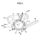
- reaction force F2 is applied from the swing rod 60 to the sub connecting rod 58A in addition to load F1 by in-tube pressure from the main connecting rod 59 to the sub connecting rod 58A, as shown in FIG. 5 . Accordingly, such resultant force FS of the load F1 by in-tube pressure and the reaction force F2 is applied from the crank pin 17c to an inner surface of the connection tubular part 57 of the sub connecting rod 58A.
- the direction of application of the resultant force FS is determined by the angle between the main connecting rod 59 and the sub connecting rod 58A, the magnitude of the force F1 applied from the main connecting rod 59 to the sub connecting rod 58A, the angle between the sub connecting rod 58A and the swing rod 60, the magnitude of the force F2 applied from the swing rod 60 to the sub connecting rod 58A. Accordingly, the direction of application of the resultant force FS is not fixed in an operation cycle of the engine, and changes as indicated by chain lines in FIG. 3 .
- the oil supply hole 70 is formed in a position deviated from a direction of application of a maximum load FSM (see FIG. 3 ) by the maximum in-tube pressure applied from the crank pin 17c to the inner surface of the connection tubular part 57.
- a maximum load FSM see FIG. 3
- the crank pin 17c relatively rotates, with respect to the sub connecting rod 58A, in the relative rotation direction indicated by an arrow 74.
- the oil supply hole 70 is formed in the upper portion of the connection tubular part 57 so as to be located immediately behind the point of application of the maximum load FSM along the relative rotation direction 74.
- the oil supply hole 70 for supplying lubricating oil to a position between the crank pin 17c and the connection tubular part 57 of the sub connecting rod 58A in the linking mechanism 56 is formed in the upper portion of the connection tubular part 57.
- the oil supply hole 70 is set in a position which is deviated from the direction of application of the maximum load FSM applied from the crank pin 17c to the inner surface of the connection tubular part 57 by the maximum in-tube pressure and which is immediately behind the point of application of the maximum load FSM along the relative rotation direction 74 of the crank pin 17c with respect to the sub connecting rod 58A.
- FIG. 6 shows a second embodiment of the present invention.
- the components corresponding to those of the first embodiment are simply denoted by the same reference numerals in the drawings and detailed descriptions thereof are omitted.
- a sub connecting rod 58B comprises: a sub connecting rod main body 61B; and a crank cap 62 fastened to the sub connecting rod main body 61B by using multiple, for example, four, bolts 63 and 63.
- the sub connecting rod main body 61B includes: a semicylinder 61a which has a cross section in a semicircular shape and into which a substantially half of a crank pin 17c is fitted; and a pair of facing plate parts 61b and 61b integrally connected respectively with two axial-direction ends of the semicylinder 61a at right angles, extending upward, and facing each other.
- the crank cap 62 includes a semicylinder 62a which has a cross section in a semicircular shape and into which the residual substantially half of the crank pin 17c is fitted.
- the sub connecting rod 58B is formed by fastening the crank cap 62 to the sub connecting rod main body 61B, and, in this state, the two semicylinders 61a and 62a form a connection tubular part 57 into which the crank pin 17c of the crankshaft 17 is relatively rotatably fitted.
- the sub connecting rod main body 61B of the sub connecting rod 58B includes a a connection plate part 61c formed integrally thereon and rising from an outer surface of the connection tubular part 57 at a position below the open end of the oil supply hole 70 at the outer surface of the connection tubular part 57 to connect the pair of facing plate parts 61b.
- An oil sump 72 communicating with the oil supply hole 70 and opened upward is formed by the outer surface of the connection tubular part 57, the two facing plate parts 61b and the connection plate part 61c.
- the same effects as those of the first embodiment can be provided, and also, since oil can be collected in the oil sump 72, oil supply from the oil supply hole 70 can be reliable.
Claims (1)
- Motor mit variablem Hub in Lenkerbauart, worin
ein Kolben (22), der verschiebbar in einen Zylinderblock (13) eingesetzt ist; eine Kurbelwelle (17), die an einem Kurbelgehäuse (12) drehbar gelagert ist; und eine Drehwelle (50), deren Achse parallel zur Kurbelwelle (17) ist und die an dem Kurbelgehäuse drehbar gelagert ist und an einer exzentrischen Position mit einer Exzenterwelle (53) versehen ist, durch einen Lenkermechanismus (56) gekoppelt sind, wobei der Lenkermechanismus (56) enthält: eine Nebenpleuelstange (58A) mit einem rohrförmigen Verbindungsteil (57), in das ein Kurbelzapfen (17c) der Kurbelwelle (17) relativ drehbar eingesetzt ist und das mit dem Kurbelzapfen (17c) relativ drehbar verbunden ist; eine Hauptpleuelstange (59), die die Nebenpleuelstange (58A) und den Kolben (22) verbindet; und eine Schwenkstange (60), die die Nebenpleuelstange (58A) und die Exzenterwelle (53) verbindet,
dadurch gekennzeichnet, dass in dem Kurbelgehäuse (22) verspritztes Öl zu einer Position zwischen dem rohrförmigen Verbindungsteil (57) der Nebenpleuelstange (58A) und dem Kurbelzapfen (17c) geführt wird,
worin ein Ölzufuhrloch (70) zum Zuführen von Schmieröl zu der Position zwischen dem rohrförmigen Verbindungsteil (57) der Nebenpleuelstange (58A) und dem Kurbelzapfen (17c) in einem oberen Abschnitt des rohrförmigen Verbindungsteils (57) an einer Position vorgesehen ist, die von einer Wirkrichtung einer maximalen Last (FSM), die von dem Kurbelzapfen (17c) auf eine Innenoberfläche des rohrförmigen Verbindungsteils (57) durch maximalen Innenrohrdruck einwirkt, versetzt ist und die unmittelbar hinter einem Wirkpunkt der maximalen Last entlang einer Richtung (74), in der sich der Kurbelzapfen (17c) relativ zu der Nebenpleuelstange (58A) dreht, liegt,
worin die Nebenpleuelstange (58A) enthält: ein Paar von einander gegenüberliegenden Plattenteilen (61 b, 61 b), die einstückig rechtwinklig an einem oberen Abschnitt des rohrförmigen Verbindungsteils (57) vorgesehen sind, um von entgegengesetzten Seiten her jeweils an der Seite der Nebenpleuelstange liegende Endabschnitte der Hauptpleuelstange (59) und der Schwenkstange (60) aufzunehmen; und
ein Verbindungsplattenteil (61 a), das von einer Außenfläche des rohrförmigen Verbindungsteils (57) an einer Position unter einem offenen Ende des Ölzufuhrlochs (70) hochsteht, um sich zu der Außenoberfläche des rohrförmigen Verbindungsteils (57) zu öffnen, wobei das Verbindungsplattenteil (61 a) die beiden gegenüberliegenden Plattenteile (61 a, 61 a) verbindet, und
ein Ölsumpf, der mit dem Ölfzufuhrloch (70) in Verbindung steht und nach oben offen ist, durch die Außenfläche des rohrförmigen Verbindungsteils (57), die gegenüberliegenden Plattenteile (61 b, 61 b) und das Verbindungsplattenteil (61 a) gebildet ist.
Applications Claiming Priority (1)
| Application Number | Priority Date | Filing Date | Title |
|---|---|---|---|
| JP2008133208A JP5014255B2 (ja) | 2008-05-21 | 2008-05-21 | リンク式ストローク可変エンジン |
Publications (2)
| Publication Number | Publication Date |
|---|---|
| EP2123869A1 EP2123869A1 (de) | 2009-11-25 |
| EP2123869B1 true EP2123869B1 (de) | 2011-05-04 |
Family
ID=40936615
Family Applications (1)
| Application Number | Title | Priority Date | Filing Date |
|---|---|---|---|
| EP09160365A Active EP2123869B1 (de) | 2008-05-21 | 2009-05-15 | Brennkraftmaschine mit variablem Kolbenhub und Multi-Gelenkgetriebe |
Country Status (5)
| Country | Link |
|---|---|
| US (1) | US8210137B2 (de) |
| EP (1) | EP2123869B1 (de) |
| JP (1) | JP5014255B2 (de) |
| AT (1) | ATE508256T1 (de) |
| DE (1) | DE602009001214D1 (de) |
Cited By (1)
| Publication number | Priority date | Publication date | Assignee | Title |
|---|---|---|---|---|
| RU2585998C1 (ru) * | 2013-02-20 | 2016-06-10 | Ниссан Мотор Ко., Лтд. | Двигатель внутреннего сгорания с переменной степенью сжатия |
Families Citing this family (12)
| Publication number | Priority date | Publication date | Assignee | Title |
|---|---|---|---|---|
| JP5629603B2 (ja) * | 2011-02-23 | 2014-11-26 | 本田技研工業株式会社 | 複リンク式可変ストロークエンジン |
| JP5634297B2 (ja) | 2011-02-23 | 2014-12-03 | 本田技研工業株式会社 | バーチカル型の複リンク式可変ストロークエンジン |
| DE102012020027A1 (de) * | 2012-10-12 | 2013-05-02 | Daimler Ag | Hubkolben-Verbrennungskraftmaschine mit einem variabel einstellbaren Verdichtungsverhältnis |
| CN105324559B (zh) * | 2013-06-20 | 2017-09-08 | 日产自动车株式会社 | 内燃机的多连杆式活塞曲柄机构的轴承构造 |
| EP3040535B1 (de) * | 2013-08-27 | 2019-02-20 | Nissan Motor Co., Ltd | Kolbenkurbelmechanismus mit mehreren verbindungen für einen verbrennungsmotor |
| WO2017037935A1 (ja) * | 2015-09-04 | 2017-03-09 | 日産自動車株式会社 | 内燃機関のピストンクランク機構におけるアッパピンの潤滑構造および潤滑方法 |
| JP6132057B2 (ja) * | 2016-06-27 | 2017-05-24 | 日産自動車株式会社 | 内燃機関の複リンク式ピストン−クランク機構の潤滑構造 |
| DE102016011392A1 (de) * | 2016-09-21 | 2018-03-22 | GM Global Technology Operations, LLC (n.d. Ges. d. Staates Delaware) | Brennkraftmaschine |
| US11391189B2 (en) * | 2018-01-31 | 2022-07-19 | Nissan Motor Co., Ltd. | Link component with oil hole |
| JP7041549B2 (ja) * | 2018-02-26 | 2022-03-24 | 日産自動車株式会社 | 内燃機関の複リンク式ピストンクランク機構 |
| JP7034195B2 (ja) * | 2020-03-18 | 2022-03-11 | 本田技研工業株式会社 | 内燃機関 |
| JP7335195B2 (ja) | 2020-04-14 | 2023-08-29 | 日産自動車株式会社 | 内燃機関のロアリンク |
Citations (1)
| Publication number | Priority date | Publication date | Assignee | Title |
|---|---|---|---|---|
| JPH01113114U (de) * | 1988-01-25 | 1989-07-31 |
Family Cites Families (23)
| Publication number | Priority date | Publication date | Assignee | Title |
|---|---|---|---|---|
| JPS54182738U (de) * | 1978-06-14 | 1979-12-25 | ||
| GB2080483B (en) * | 1980-07-18 | 1984-06-13 | Rees John Douglas | Piston rods |
| JPS5867115U (ja) * | 1981-10-30 | 1983-05-07 | 日産ディーゼル工業株式会社 | コネクテイングロツド |
| US4517931A (en) * | 1983-06-30 | 1985-05-21 | Nelson Carl D | Variable stroke engine |
| JPS61109913U (de) * | 1984-12-13 | 1986-07-11 | ||
| JPS62105313U (de) * | 1985-12-20 | 1987-07-04 | ||
| DE3638783A1 (de) * | 1986-11-13 | 1988-05-26 | Daimler Benz Ag | Vorrichtung zur steuerung des oelzulaufes in eine steuerkammer eines kolbens mit veraenderbarer kompressionshoehe |
| JPH01113114A (ja) | 1987-10-23 | 1989-05-01 | Furukawa Electric Co Ltd:The | 伝熱管の製造方法 |
| JPH01157212U (de) * | 1988-04-19 | 1989-10-30 | ||
| JPH04119213A (ja) * | 1990-05-11 | 1992-04-20 | Kubota Corp | 連接棒 |
| JPH11294444A (ja) * | 1998-04-07 | 1999-10-26 | Mitsubishi Heavy Ind Ltd | コンロッド及び往復動型機関 |
| US6167851B1 (en) * | 1998-07-15 | 2001-01-02 | William M. Bowling | Movable crankpin, variable compression-ratio, piston engine |
| JP3784607B2 (ja) * | 2000-03-21 | 2006-06-14 | 本田技研工業株式会社 | ハンドヘルド型四サイクルエンジンにおけるオイルミスト生成装置 |
| US6422194B2 (en) * | 2000-03-16 | 2002-07-23 | Honda Giken Kogyo Kabushiki Kaisha | Handheld type four-cycle engine |
| JP4062867B2 (ja) * | 2000-07-31 | 2008-03-19 | 日産自動車株式会社 | 可変圧縮比機構を備えた内燃機関 |
| JP3941371B2 (ja) * | 2000-10-12 | 2007-07-04 | 日産自動車株式会社 | 内燃機関の可変圧縮比機構 |
| JP2003343297A (ja) * | 2002-03-20 | 2003-12-03 | Honda Motor Co Ltd | エンジン |
| JP4025562B2 (ja) * | 2002-03-20 | 2007-12-19 | 本田技研工業株式会社 | 圧縮比可変エンジン |
| JP2003314211A (ja) * | 2002-04-17 | 2003-11-06 | Honda Motor Co Ltd | ストローク可変エンジン |
| US7703431B2 (en) * | 2002-07-26 | 2010-04-27 | Cummins, Inc. | Connecting rod apparatus and method |
| JP4090961B2 (ja) * | 2003-07-22 | 2008-05-28 | 本田技研工業株式会社 | エンジンのクランクケース構造 |
| JP4443214B2 (ja) * | 2003-12-26 | 2010-03-31 | 富士重工業株式会社 | エンジンのコンロッド大端部周りの潤滑構造 |
| JP4535899B2 (ja) * | 2005-02-14 | 2010-09-01 | 本田技研工業株式会社 | ストローク特性可変エンジン |
-
2008
- 2008-05-21 JP JP2008133208A patent/JP5014255B2/ja not_active Expired - Fee Related
-
2009
- 2009-05-15 EP EP09160365A patent/EP2123869B1/de active Active
- 2009-05-15 AT AT09160365T patent/ATE508256T1/de not_active IP Right Cessation
- 2009-05-15 DE DE602009001214T patent/DE602009001214D1/de active Active
- 2009-05-21 US US12/469,806 patent/US8210137B2/en active Active
Patent Citations (1)
| Publication number | Priority date | Publication date | Assignee | Title |
|---|---|---|---|---|
| JPH01113114U (de) * | 1988-01-25 | 1989-07-31 |
Cited By (1)
| Publication number | Priority date | Publication date | Assignee | Title |
|---|---|---|---|---|
| RU2585998C1 (ru) * | 2013-02-20 | 2016-06-10 | Ниссан Мотор Ко., Лтд. | Двигатель внутреннего сгорания с переменной степенью сжатия |
Also Published As
| Publication number | Publication date |
|---|---|
| DE602009001214D1 (de) | 2011-06-16 |
| ATE508256T1 (de) | 2011-05-15 |
| US8210137B2 (en) | 2012-07-03 |
| US20090288643A1 (en) | 2009-11-26 |
| JP5014255B2 (ja) | 2012-08-29 |
| EP2123869A1 (de) | 2009-11-25 |
| JP2009281242A (ja) | 2009-12-03 |
Similar Documents
| Publication | Publication Date | Title |
|---|---|---|
| EP2123869B1 (de) | Brennkraftmaschine mit variablem Kolbenhub und Multi-Gelenkgetriebe | |
| KR100576964B1 (ko) | 스트로크 가변 엔진 | |
| KR100474424B1 (ko) | 엔진 | |
| EP2048335B1 (de) | Brennkraftmaschine mit variabeln Kolbenhub | |
| EP2119890B1 (de) | Brennkraftmaschine mit variablem Kolbenhub und Gelenkgetriebe | |
| US8826874B2 (en) | Anti-rotation roller valve lifter | |
| EP2048336B1 (de) | Brennkraftmaschine mit variabeln Kolbenhub | |
| EP1426585B1 (de) | Brennkraftmaschine mit variabeln Kolbenhub | |
| US7246552B2 (en) | Piston having asymmetrical pin bore slot placement | |
| EP1895112B1 (de) | Ventiltrieb eines motors | |
| JP4025622B2 (ja) | 汎用単気筒エンジン | |
| US8161922B2 (en) | Link type variable stroke engine | |
| EP2136049B1 (de) | Brennkraftmaschine mit variablen Kolbenhub | |
| WO2022030219A1 (ja) | 内燃機関 | |
| JP7172536B2 (ja) | 可変圧縮比内燃機関 |
Legal Events
| Date | Code | Title | Description |
|---|---|---|---|
| PUAI | Public reference made under article 153(3) epc to a published international application that has entered the european phase |
Free format text: ORIGINAL CODE: 0009012 |
|
| 17P | Request for examination filed |
Effective date: 20090515 |
|
| AK | Designated contracting states |
Kind code of ref document: A1 Designated state(s): AT BE BG CH CY CZ DE DK EE ES FI FR GB GR HR HU IE IS IT LI LT LU LV MC MK MT NL NO PL PT RO SE SI SK TR |
|
| RIC1 | Information provided on ipc code assigned before grant |
Ipc: F01M 11/02 20060101ALI20100906BHEP Ipc: F01M 9/06 20060101AFI20100906BHEP Ipc: F02B 41/04 20060101ALI20100906BHEP |
|
| GRAP | Despatch of communication of intention to grant a patent |
Free format text: ORIGINAL CODE: EPIDOSNIGR1 |
|
| GRAS | Grant fee paid |
Free format text: ORIGINAL CODE: EPIDOSNIGR3 |
|
| GRAA | (expected) grant |
Free format text: ORIGINAL CODE: 0009210 |
|
| RIN1 | Information on inventor provided before grant (corrected) |
Inventor name: SATO, YOSHIKAZU Inventor name: KONO, SHOHEI |
|
| AK | Designated contracting states |
Kind code of ref document: B1 Designated state(s): AT BE BG CH CY CZ DE DK EE ES FI FR GB GR HR HU IE IS IT LI LT LU LV MC MK MT NL NO PL PT RO SE SI SK TR |
|
| REG | Reference to a national code |
Ref country code: GB Ref legal event code: FG4D |
|
| REG | Reference to a national code |
Ref country code: CH Ref legal event code: EP |
|
| REG | Reference to a national code |
Ref country code: IE Ref legal event code: FG4D |
|
| REF | Corresponds to: |
Ref document number: 602009001214 Country of ref document: DE Date of ref document: 20110616 Kind code of ref document: P |
|
| REG | Reference to a national code |
Ref country code: DE Ref legal event code: R096 Ref document number: 602009001214 Country of ref document: DE Effective date: 20110616 |
|
| REG | Reference to a national code |
Ref country code: NL Ref legal event code: VDEP Effective date: 20110504 |
|
| PG25 | Lapsed in a contracting state [announced via postgrant information from national office to epo] |
Ref country code: LT Free format text: LAPSE BECAUSE OF FAILURE TO SUBMIT A TRANSLATION OF THE DESCRIPTION OR TO PAY THE FEE WITHIN THE PRESCRIBED TIME-LIMIT Effective date: 20110504 Ref country code: NO Free format text: LAPSE BECAUSE OF FAILURE TO SUBMIT A TRANSLATION OF THE DESCRIPTION OR TO PAY THE FEE WITHIN THE PRESCRIBED TIME-LIMIT Effective date: 20110804 Ref country code: PT Free format text: LAPSE BECAUSE OF FAILURE TO SUBMIT A TRANSLATION OF THE DESCRIPTION OR TO PAY THE FEE WITHIN THE PRESCRIBED TIME-LIMIT Effective date: 20110905 Ref country code: SE Free format text: LAPSE BECAUSE OF FAILURE TO SUBMIT A TRANSLATION OF THE DESCRIPTION OR TO PAY THE FEE WITHIN THE PRESCRIBED TIME-LIMIT Effective date: 20110504 |
|
| PG25 | Lapsed in a contracting state [announced via postgrant information from national office to epo] |
Ref country code: IS Free format text: LAPSE BECAUSE OF FAILURE TO SUBMIT A TRANSLATION OF THE DESCRIPTION OR TO PAY THE FEE WITHIN THE PRESCRIBED TIME-LIMIT Effective date: 20110904 Ref country code: FI Free format text: LAPSE BECAUSE OF FAILURE TO SUBMIT A TRANSLATION OF THE DESCRIPTION OR TO PAY THE FEE WITHIN THE PRESCRIBED TIME-LIMIT Effective date: 20110504 Ref country code: AT Free format text: LAPSE BECAUSE OF FAILURE TO SUBMIT A TRANSLATION OF THE DESCRIPTION OR TO PAY THE FEE WITHIN THE PRESCRIBED TIME-LIMIT Effective date: 20110504 Ref country code: GR Free format text: LAPSE BECAUSE OF FAILURE TO SUBMIT A TRANSLATION OF THE DESCRIPTION OR TO PAY THE FEE WITHIN THE PRESCRIBED TIME-LIMIT Effective date: 20110805 Ref country code: SI Free format text: LAPSE BECAUSE OF FAILURE TO SUBMIT A TRANSLATION OF THE DESCRIPTION OR TO PAY THE FEE WITHIN THE PRESCRIBED TIME-LIMIT Effective date: 20110504 Ref country code: BE Free format text: LAPSE BECAUSE OF FAILURE TO SUBMIT A TRANSLATION OF THE DESCRIPTION OR TO PAY THE FEE WITHIN THE PRESCRIBED TIME-LIMIT Effective date: 20110504 Ref country code: CY Free format text: LAPSE BECAUSE OF FAILURE TO SUBMIT A TRANSLATION OF THE DESCRIPTION OR TO PAY THE FEE WITHIN THE PRESCRIBED TIME-LIMIT Effective date: 20110504 Ref country code: LV Free format text: LAPSE BECAUSE OF FAILURE TO SUBMIT A TRANSLATION OF THE DESCRIPTION OR TO PAY THE FEE WITHIN THE PRESCRIBED TIME-LIMIT Effective date: 20110504 Ref country code: ES Free format text: LAPSE BECAUSE OF FAILURE TO SUBMIT A TRANSLATION OF THE DESCRIPTION OR TO PAY THE FEE WITHIN THE PRESCRIBED TIME-LIMIT Effective date: 20110815 |
|
| PG25 | Lapsed in a contracting state [announced via postgrant information from national office to epo] |
Ref country code: MC Free format text: LAPSE BECAUSE OF NON-PAYMENT OF DUE FEES Effective date: 20110531 Ref country code: NL Free format text: LAPSE BECAUSE OF FAILURE TO SUBMIT A TRANSLATION OF THE DESCRIPTION OR TO PAY THE FEE WITHIN THE PRESCRIBED TIME-LIMIT Effective date: 20110504 Ref country code: MT Free format text: LAPSE BECAUSE OF FAILURE TO SUBMIT A TRANSLATION OF THE DESCRIPTION OR TO PAY THE FEE WITHIN THE PRESCRIBED TIME-LIMIT Effective date: 20110504 |
|
| PG25 | Lapsed in a contracting state [announced via postgrant information from national office to epo] |
Ref country code: CZ Free format text: LAPSE BECAUSE OF FAILURE TO SUBMIT A TRANSLATION OF THE DESCRIPTION OR TO PAY THE FEE WITHIN THE PRESCRIBED TIME-LIMIT Effective date: 20110504 Ref country code: EE Free format text: LAPSE BECAUSE OF FAILURE TO SUBMIT A TRANSLATION OF THE DESCRIPTION OR TO PAY THE FEE WITHIN THE PRESCRIBED TIME-LIMIT Effective date: 20110504 |
|
| PG25 | Lapsed in a contracting state [announced via postgrant information from national office to epo] |
Ref country code: PL Free format text: LAPSE BECAUSE OF FAILURE TO SUBMIT A TRANSLATION OF THE DESCRIPTION OR TO PAY THE FEE WITHIN THE PRESCRIBED TIME-LIMIT Effective date: 20110504 Ref country code: SK Free format text: LAPSE BECAUSE OF FAILURE TO SUBMIT A TRANSLATION OF THE DESCRIPTION OR TO PAY THE FEE WITHIN THE PRESCRIBED TIME-LIMIT Effective date: 20110504 |
|
| REG | Reference to a national code |
Ref country code: IE Ref legal event code: MM4A |
|
| PLBE | No opposition filed within time limit |
Free format text: ORIGINAL CODE: 0009261 |
|
| STAA | Information on the status of an ep patent application or granted ep patent |
Free format text: STATUS: NO OPPOSITION FILED WITHIN TIME LIMIT |
|
| 26N | No opposition filed |
Effective date: 20120207 |
|
| PG25 | Lapsed in a contracting state [announced via postgrant information from national office to epo] |
Ref country code: IE Free format text: LAPSE BECAUSE OF NON-PAYMENT OF DUE FEES Effective date: 20110515 |
|
| PG25 | Lapsed in a contracting state [announced via postgrant information from national office to epo] |
Ref country code: HR Free format text: LAPSE BECAUSE OF FAILURE TO SUBMIT A TRANSLATION OF THE DESCRIPTION OR TO PAY THE FEE WITHIN THE PRESCRIBED TIME-LIMIT Effective date: 20111123 Ref country code: IT Free format text: LAPSE BECAUSE OF FAILURE TO SUBMIT A TRANSLATION OF THE DESCRIPTION OR TO PAY THE FEE WITHIN THE PRESCRIBED TIME-LIMIT Effective date: 20110504 |
|
| REG | Reference to a national code |
Ref country code: DE Ref legal event code: R097 Ref document number: 602009001214 Country of ref document: DE Effective date: 20120207 |
|
| PG25 | Lapsed in a contracting state [announced via postgrant information from national office to epo] |
Ref country code: MK Free format text: LAPSE BECAUSE OF FAILURE TO SUBMIT A TRANSLATION OF THE DESCRIPTION OR TO PAY THE FEE WITHIN THE PRESCRIBED TIME-LIMIT Effective date: 20110504 |
|
| PG25 | Lapsed in a contracting state [announced via postgrant information from national office to epo] |
Ref country code: LU Free format text: LAPSE BECAUSE OF NON-PAYMENT OF DUE FEES Effective date: 20110515 |
|
| PG25 | Lapsed in a contracting state [announced via postgrant information from national office to epo] |
Ref country code: BG Free format text: LAPSE BECAUSE OF FAILURE TO SUBMIT A TRANSLATION OF THE DESCRIPTION OR TO PAY THE FEE WITHIN THE PRESCRIBED TIME-LIMIT Effective date: 20110804 |
|
| PG25 | Lapsed in a contracting state [announced via postgrant information from national office to epo] |
Ref country code: TR Free format text: LAPSE BECAUSE OF FAILURE TO SUBMIT A TRANSLATION OF THE DESCRIPTION OR TO PAY THE FEE WITHIN THE PRESCRIBED TIME-LIMIT Effective date: 20110504 |
|
| PG25 | Lapsed in a contracting state [announced via postgrant information from national office to epo] |
Ref country code: HU Free format text: LAPSE BECAUSE OF FAILURE TO SUBMIT A TRANSLATION OF THE DESCRIPTION OR TO PAY THE FEE WITHIN THE PRESCRIBED TIME-LIMIT Effective date: 20110504 |
|
| PG25 | Lapsed in a contracting state [announced via postgrant information from national office to epo] |
Ref country code: HR Free format text: LAPSE BECAUSE OF FAILURE TO SUBMIT A TRANSLATION OF THE DESCRIPTION OR TO PAY THE FEE WITHIN THE PRESCRIBED TIME-LIMIT Effective date: 20110504 |
|
| REG | Reference to a national code |
Ref country code: CH Ref legal event code: PL |
|
| PG25 | Lapsed in a contracting state [announced via postgrant information from national office to epo] |
Ref country code: CH Free format text: LAPSE BECAUSE OF NON-PAYMENT OF DUE FEES Effective date: 20130531 Ref country code: LI Free format text: LAPSE BECAUSE OF NON-PAYMENT OF DUE FEES Effective date: 20130531 |
|
| PGFP | Annual fee paid to national office [announced via postgrant information from national office to epo] |
Ref country code: GB Payment date: 20140514 Year of fee payment: 6 |
|
| PGFP | Annual fee paid to national office [announced via postgrant information from national office to epo] |
Ref country code: FR Payment date: 20140509 Year of fee payment: 6 |
|
| GBPC | Gb: european patent ceased through non-payment of renewal fee |
Effective date: 20150515 |
|
| REG | Reference to a national code |
Ref country code: FR Ref legal event code: ST Effective date: 20160129 |
|
| PG25 | Lapsed in a contracting state [announced via postgrant information from national office to epo] |
Ref country code: GB Free format text: LAPSE BECAUSE OF NON-PAYMENT OF DUE FEES Effective date: 20150515 |
|
| PG25 | Lapsed in a contracting state [announced via postgrant information from national office to epo] |
Ref country code: FR Free format text: LAPSE BECAUSE OF NON-PAYMENT OF DUE FEES Effective date: 20150601 |
|
| REG | Reference to a national code |
Ref country code: DE Ref legal event code: R084 Ref document number: 602009001214 Country of ref document: DE |
|
| PGFP | Annual fee paid to national office [announced via postgrant information from national office to epo] |
Ref country code: DE Payment date: 20210420 Year of fee payment: 13 |
|
| REG | Reference to a national code |
Ref country code: DE Ref legal event code: R119 Ref document number: 602009001214 Country of ref document: DE |
|
| PG25 | Lapsed in a contracting state [announced via postgrant information from national office to epo] |
Ref country code: DE Free format text: LAPSE BECAUSE OF NON-PAYMENT OF DUE FEES Effective date: 20221201 |