EP2136049B1 - Brennkraftmaschine mit variablen Kolbenhub - Google Patents
Brennkraftmaschine mit variablen Kolbenhub Download PDFInfo
- Publication number
- EP2136049B1 EP2136049B1 EP09160110A EP09160110A EP2136049B1 EP 2136049 B1 EP2136049 B1 EP 2136049B1 EP 09160110 A EP09160110 A EP 09160110A EP 09160110 A EP09160110 A EP 09160110A EP 2136049 B1 EP2136049 B1 EP 2136049B1
- Authority
- EP
- European Patent Office
- Prior art keywords
- crankshaft
- main body
- case main
- rotary shaft
- support plate
- Prior art date
- Legal status (The legal status is an assumption and is not a legal conclusion. Google has not performed a legal analysis and makes no representation as to the accuracy of the status listed.)
- Not-in-force
Links
Images


Classifications
-
- F—MECHANICAL ENGINEERING; LIGHTING; HEATING; WEAPONS; BLASTING
- F02—COMBUSTION ENGINES; HOT-GAS OR COMBUSTION-PRODUCT ENGINE PLANTS
- F02B—INTERNAL-COMBUSTION PISTON ENGINES; COMBUSTION ENGINES IN GENERAL
- F02B41/00—Engines characterised by special means for improving conversion of heat or pressure energy into mechanical power
- F02B41/02—Engines with prolonged expansion
- F02B41/04—Engines with prolonged expansion in main cylinders
-
- F—MECHANICAL ENGINEERING; LIGHTING; HEATING; WEAPONS; BLASTING
- F02—COMBUSTION ENGINES; HOT-GAS OR COMBUSTION-PRODUCT ENGINE PLANTS
- F02B—INTERNAL-COMBUSTION PISTON ENGINES; COMBUSTION ENGINES IN GENERAL
- F02B75/00—Other engines
- F02B75/04—Engines with variable distances between pistons at top dead-centre positions and cylinder heads
- F02B75/048—Engines with variable distances between pistons at top dead-centre positions and cylinder heads by means of a variable crank stroke length
Definitions
- the present invention relates to a link type variable stroke engine, and especially relates to a link type variable stroke engine in which a crankshaft and a rotary shaft are each rotatably supported on a case main body and a support plate, the case main body formed integrally with a cylinder block and opened at one side to form a part of a crankcase, the support plate fastened to an opened end of the case main body at a plurality of positions, the rotary shaft having an axis parallel with the crankshaft and being provided with an eccentric shaft at an eccentric position, a piston slidably fitted to the cylinder block, the crankshaft and the eccentric shaft are linked by a linking mechanism, and the linking mechanism includes: a main connecting rod coupled, at one end, with the piston; a sub connecting rod rotatably coupled with a crank pin of the crankshaft and rotatably coupled with the other end of the main connecting rod; and a swing rod rotatably coupled, at one end, with the sub connecting rod at a position displaced from a position coupled
- a crankcase includes a case main body integrally formed with a cylinder block and opened at one side, and a side cover fastened to the opened end of the case main body, and in which the crankshaft is rotatably supported by the case main body and the side cover, it is not necessary to take into account any directional properties, except for the above, in terms of fastening positions at which the side cover is to be fastened to the case main body.
- the fastening positions can be any positions as long as being provided at substantially regular intervals to prevent oil leak from coupled parts of the case main body and the side cover.
- a link type variable stroke engine has already been known by Japanese Utility Model Publication No. 57-32267 , Japanese Patent Application Laid-open No. 9-228858 , the specification of United States Patent No. 4517931 , Japanese Patent Application Laid-open No. 2002-285877 and the like.
- the link type variable stroke engine a piston, a crankshaft and an eccentric shaft are linked by a linking mechanism, the eccentric shaft provided to a rotary shaft which is parallel with the crankshaft and to which power reduced at a speed reduction ratio of 1/2 from the crankshaft is transmitted.
- internal load components of force
- EP 1 359 303 A2 discloses a link type variable stroke engine in which a crankshaft and a rotary shaft are each rotatably supported on a case main body and a support plate, the case main body formed integrally with a cylinder block and opened at one side to form a part of a crankcase, the support plate fastened to an opened end of the case main body at a plurality of positions, the rotary shaft having an axis parallel with the crankshaft and being provided with an eccentric shaft at an eccentric position, a piston slidably fitted to the cylinder block, the crankshaft and the eccentric shaft are linked by a linking mechanism, and the linking mechanism includes: a main connecting rod coupled, at one end, with the piston; a sub connecting rod rotatably coupled with a crank pin of the crankshaft and rotatably coupled with the other end of the main connecting rod; and a swing rod rotatably coupled, at one end, with the sub connecting rod at a position displaced
- the present invention has been made in view of the above-described circumstances. It is an object of the present invention to provide a link type variable stroke engine with sufficiently increased rigidity between a crankshaft and a rotary shaft, thereby preventing the above-described problems (1) to (4).
- a crankshaft and a rotary shaft are each rotatably supported on a case main body and a support plate, the case main body formed integrally with a cylinder block and opened at one side to form a part of a crankcase, the support plate fastened to an opened end of the case main body at a plurality of positions, the rotary shaft having an axis parallel with the crankshaft and being provided with an eccentric shaft at an eccentric position, a piston slidably fitted to the cylinder block, the crankshaft and the eccentric shaft are linked by a linking mechanism, and the linking mechanism includes: a main connecting rod coupled, at one end, with the piston; a sub connecting rod rotatably coupled with a crank pin of the crankshaft and rotatably coupled with the other end of the main connecting rod; and a swing rod rotatably coupled, at one end, with the sub connecting rod at a position displaced from a position coupled with the main connecting rod and rotatably coupled, at the other end, with the eccentric shaft, wherein, in
- the support plate is a side cover fastened to the opened end of the case main body so as to close the opened end of the case main body for forming the crankcase in cooperation with the case main body.
- a side cover and the support plate are each fastened to the opened end of the case main body, the side cover closing the opened end of the case main body for forming the crankcase in cooperation with the case main body, the support plate disposed inwardly of the side cover.
- two of the multiple fastening positions at which the support plate is fastened to the opened end of the case main body are disposed on the straight line passing the axes of the rotary shaft and the crankshaft in a projection view on a plane orthogonal to the axes of the crankshaft and the rotary shaft.
- FIG. 1 to FIG. 3 show a first embodiment of the present invention:
- FIG. 1 is a longitudinal cross-sectional side view of an engine and a cross-sectional view taken along a line 1-1 in FIG. 2;
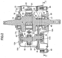
- FIG. 2 is a cross-sectional view taken along a line 2-2 in FIG. 1 ;
- FIG. 3 is a cross-sectional view taken along a line 3-3 in FIG. 1 .
- FIG. 4 and FIG. 5 show a second embodiment of the present invention:
- FIG. 4 is a cross-sectional view corresponding to FIG. 2 ; and
- FIG. 5 is a cross-sectional view taken along a line 5-5 in FIG. 4 .
- FIG. 1 to FIG. 3 A first embodiment of the present invention will be explained below based on FIG. 1 to FIG. 3 .
- this link type variable stroke engine is an air-cooled single cylinder engine, which is used for working machines and the like, for example.
- An engine body 11A includes: a crankcase 12A; a cylinder block 13 protruding in upwardly tilting manner from one side surface of the crankcase 12A; and a cylinder head 14 joined to a head portion of the cylinder block 13.
- a large number of air-cooling fins 13a and 14a are provided on outer side surfaces of the cylinder block 13 and the cylinder head 14.
- the crankcase 12A comprises: a case main body 15A formed integrally with the cylinder block 13 by molding and opened at one side; and a side cover 16A fastened to the opened end of the case main body 15A and served as a support plate.
- a crankshaft 17 is rotatably supported in the crankcase 12A.
- the crankshaft 17 integrally has a pair of counterweights 17a and 17b, as well as a crank pin 17c which connects between the counterweights 17a and 17b. Accordingly, both end portions of the crankshaft 17 rotatably penetrate the case main body 15A and the side cover 16A of the crankcase 12 and protrude outwardly.
- a ball bearing 18 and an annular sealing member 19 are disposed between the crankshaft 17 and the case main body 15A, the sealing member 19 disposed on the outer side of the ball bearing 18, and a ball bearing 20 and an annular sealing member 21 are disposed between the crankshaft 17 and the side cover 16A, the sealing member 21 disposed on the outer side of the ball bearing 20.
- a cylinder bore 23 is formed in the cylinder block 13.
- a piston 22 is slidably fitted in the cylinder bore 23.
- a combustion chamber 24 is formed between the cylinder block 13 and the cylinder head 14, and a top portion of the piston 22 faces the combustion chamber 24.
- An intake port 25 and an exhaust port 26, both communicating with the combustion chamber 24, are formed in the cylinder head 14.
- an intake valve 27 for opening and closing the passage between the intake port 25 and the combustion chamber 24 as well as an exhaust valve 28 for opening and closing the passage between the exhaust port 26 and the combustion chamber 24 are disposed in the cylinder head 14 so as to be capable of performing the opening and closing operations.
- a valve operating mechanism 30 opening and closing the intake valve 27 and the exhaust valve 28 includes: a valve operating cam 31 rotated by the crankshaft 17 at a speed reduction ratio of 1/2; and intake-side and exhaust-side rocker arms 32 and 33 which are each, at one end, in sliding contact with the valve operating cam 31 while tappet screws 34 and 35 are threaded respectively into the other ends of the rocker arms 32 and 33 so that the forward/backward movement positions thereof can be adjusted, the tappet screws 32 and 33 being abutted against upper end portions of the intake valve 27 and the exhaust valve 28, respectively.
- the valve operating cam 31 is rotatably supported by a first spindle 36 which has an axis parallel with the crankshaft 17 and which is fixedly supported at the cylinder head 14, and the intake-side and exhaust-side rocker arms 32 and 33 are swingably supported by a second spindle 37 which has an axis parallel with the first spindle 36 and which is supported at the cylinder head 14.
- fitting holes 39a and 39b for the first spindle 36 to be fitted therein are formed with a space therebetween so as to have the same axis, and the fitting hole 39b is formed so as to be opened at one side surface of the cylinder head 14.
- the valve operating mechanism 30 is covered with a head cover 40.
- the head cover 40 includes an engagement portion 40a which is engaged with a protruding end of the first spindle 36 protruding from the fitting hole 39b, so as to prevent the first spindle 36 from coming out of the fitting hole 39b and rotating about the axis.
- the head cover 40 is joined to the cylinder head 14.
- a rotary shaft 41A Opposite end portions of a rotary shaft 41A are rotatably supported at the case main body 15A and the side cover 16A of the crankcase 12 with ball bearings 63 and 64, respectively, the rotary shaft 41A having an axis parallel with the crankshaft 17 while having a rotation axis above a rotation axis of the crankshaft 17.
- first timing transmitting means 42 is disposed which reduces the rotation power of the crankshaft 17 at a speed reduction ratio of 1/2 and then transmits the rotation power to the rotary shaft 41A.
- second timing transmitting means 43 is disposed which reduces the rotation power of the crankshaft 17 at a speed reduction ratio of 1/2 and then transmits the rotation power to the valve operating cam 31.
- the first and second timing transmitting means 42 and 43 are disposed between the side cover 16A and the counterweight 17b of the pair of counterweights 17a and 17b of the crankshaft 17, to be adjacent to each other in an axial direction of the crankshaft 17.
- the first timing transmitting means 42 includes: a driving gear 44 fixed to the crankshaft 17; and a driven gear 45 coupled with the rotary shaft 41A so that relative rotation therebetween would not be possible and the driven gear 45 would mesh with the driving gear 44.
- the second timing transmitting means 43 includes: a driving sprocket 46 provided integrally with the crankshaft 17; a driven sprocket 47 fixedly attached to the valve operating cam 31; and a timing belt 48 wound around the driving sprocket 46 and the driven sprocket 47.
- a timing belt chamber 49 in which the timing belt 48 travels is formed in the cylinder block 13 and the cylinder head 14.
- An eccentric shaft 50 is provided integrally with the rotary shaft 41A at a position corresponding to a portion between the pair of counterweights 17a and 17b of the crankshaft 17.
- the eccentric shaft 50 has its axis at a position eccentric with respect to the axis of the rotary shaft 41A.
- the eccentric shaft 50, the piston 22 and the crankshaft 17 are linked by a linking mechanism 51.
- the linking mechanism 51 comprises: a main connecting rod 53 coupled, at one end, with the piston 22 by using a piston pin 52; a sub connecting rod 54 disposed between the counterweights 17a and 17b of the crankshaft 17 to be coupled with the crank pin 17c and to be rotatably coupled with the other end of the main connecting rod 53; and a swing rod 55 rotatably connected, at one end, with the sub connecting rod 54 at a position displaced from the coupled position of the main connecting rod 53, and rotatably coupled, at the other end, with the eccentric shaft 50.
- the sub connecting rod 54 is formed so as to be in sliding contact with half of the circumference of the crank pin 17c.
- a crank cap 56 is disposed to be in sliding contact with the other half of the circumference of the crank pin 17c, and is fastened to the sub connecting rod 54 with a plurality of bolts 57 and 57.
- the crank cap 56 is provided with an oil dipper 58 for dipping up oil stored in the crankcase 12A.
- the other end portion of the main connecting rod 53 is rotatably coupled with the one end portion of the sub connecting rod 54 by using a connecting rod pin 59.
- the one end portion of the swing rod 55 is rotatably coupled with the sub connecting rod 54 by using a swing pin 60.
- a circular shaft hole 61, which the eccentric shaft 50 penetrates, is formed in the other end portion of the swing rod 55, and a needle bearing 62 is provided between the swing rod 55 and the eccentric shaft 50.
- the linking mechanism 51 operates, for example, in a manner that the stroke of the piston 22 in the expansion stroke becomes larger than that in the compression stroke.
- reaction forces F2 and F3 occur at the crankshaft 17 and the rotary shaft 41A while components of force F2' and F3' of the reaction forces F2 and F3 occur on a straight line L1 passing the axes of the rotary shaft 41A and the crankshaft 17.
- the side cover 16A is fastened to the opened end of the case main body 15A at multiple positions, for example, seven positions, by using bolts 66 and 66, to form the crankcase 12A together with the case main body 15A.
- two of the multiple fastening positions at which the side cover 16A is fastened to the opened end of the case main body 15A are disposed on the straight line L1 passing the axes of the rotary shaft 41A and the crankshaft 17 in the projection view.
- two bolts 66 and 66 of the multiple bolts 66 and 66 are disposed on the straight line L1 on a plane orthogonal to the axes of the rotary shaft 41A and the crankshaft 17.
- Two of the multiple fastening positions at which the side cover 16A is fastened to the opened end of the case main body 15A are disposed on the straight line L1 passing the axes of the rotary shaft 41A and the crankshaft 17 in a projection view on a plane orthogonal to the axes of the crankshaft 17 and the rotary shaft 41A.
- This configuration can increase the rigidity between the crankshaft 17 and the rotary shaft 41A enough to be capable of bearing the internal load occurring between the crankshaft 17 and the rotary shaft 41A, consequently preventing change of the distance between the crankshaft 17 and the rotary shaft 41A.
- FIGS. 4 and 5 a second embodiment of the present invention will be explained with reference to FIGS. 4 and 5 .
- the components corresponding to those of the first embodiment in FIGS. 1 to 3 are simply denoted by the same reference numerals in the drawings and detailed descriptions thereof are omitted.
- a crankcase 12B comprises: a case main body 15B formed integrally with a cylinder block 13 by molding and opened at one side; and a side cover 16B fastened to the case main body 15B.
- the side cover 16B covering the opened end of the case main body 15B and a support plate 67 disposed inside of the side cover 16B are respectively fastened to the opened end of the case main body 15B.
- the side cover 16B is fastened to an opened end of the case main body 15B by using multiple, for example, eight, bolts 68 and 68, and the support plate 67 is fastened to the opened end of the case main body 15B by using multiple, for example, six, bolts 69 and 69.
- a crankshaft 17 integrally has a pair of counterweights 17a and 17b, as well as a crank pin 17c which connects between the counterweights 17a and 17b.
- One end portion of the crankshaft 17 rotatably penetrates the case main body 15B of the crankcase 12B and protrudes outwardly.
- the other end portion of the crankshaft 17 rotatably penetrates the support plate 67 and the side cover 16B and protrudes outwardly.
- a ball bearing 18 and an annular sealing member 19 are disposed between the crankshaft 17 and the case main body 15B, the sealing member 19 disposed on the outer side of the ball bearing 18.
- a ball bearing 20 is disposed between the crankshaft 17 and the support plate 67, and an annular sealing member 21 is disposed between the side cover 16B and the crankshaft 17.
- first timing transmitting means 42 is disposed which reduces the rotation power of the crankshaft 17 at a speed reduction ratio of 1/2 and then transmits the rotation power to the rotary shaft 41B.
- the first timing transmitting means 42 comprises: a driving gear 44 fixed to the crankshaft 17; and a driven gear 45 coupled with the rotary shaft 41B so that relative rotation therebetween would not be possible and the driven gear 45 would mesh with the driving gear 44.
- a driving sprocket 46 is fixed to a portion of the crankshaft 17, the portion being between the driving gear 44 and the side cover 16B, and a timing belt 48 is looped around the driving sprocket 46.
- the driving sprocket 46 and the timing belt 48 form a part of second timing transmitting means 43 which reduces the rotation power of the crankshaft 17 at a reduction ratio of 1/2 and then transmits the rotation power to a valve operating mechanism 30 (see the first embodiment) side.
- An eccentric shaft 50 is provided integrally with the rotary shaft 41B at a position corresponding to a portion between the pair of counterweights 17a and 17b of the crankshaft 17.
- the eccentric shaft 50 has its axis at a position eccentric with respect to the axis of the rotary shaft 41B.
- the eccentric shaft 50, a piston 22 and the crankshaft 17 are linked by a linking mechanism 51.
- the support plate 67 is disposed so that the first and second timing transmitting means 42 and 43 are interposed between the support plate 67 and the side cover 16B forming a part of the crankcase 12B.
- the crankshaft 17 and the rotary shaft 41B are rotatably supported at the case main body 15B of the crankcase 12B and the support plate 67 by using the ball bearings 18 and 20 as well as 63 and 64.
- This configuration can shorten, in each of the crankshaft 17 and the rotary shaft 41B, the distance between a point of load application and each of the corresponding pair of ball bearings 18 and 20 or 63 and 64, which are provided respectively on both sides of the load application point, the point of load application being a point at which load is applied due to explosion load applied to a piston 22 (see the first embodiment). Moreover, the distances can be made approximately equal on the left side and the right side in this embodiment.
- the support plate 67 is fastened to the opened end of the case main body 15B by using multiple, for example, six, bolts 69 and 69.
- two of the multiple fastening positions at which the support plate 67 is fastened to the opened end of the case main body 15B are disposed on a straight line L2 passing the axes of the rotary shaft 41B and the crankshaft 17 in a projection view on a plane orthogonal to the axes of the crankshaft 17 and the rotary shaft 41B.
- two bolts 69 and 69 of the multiple bolts 69 and 69 are provided on the straight line L2 on a plane orthogonal to the axes of the rotary shaft 41B and the crankshaft 17.
- the distances from the point of load application respectively to the corresponding ball bearings 18 and 20 or 63 and 64, which are provided on the left and right sides of the point of load application, are made approximately equal, the support rigidity on the right side and the support rigidity on the left side can be equal, preventing the crankshaft 17 and the rotary shaft 41B from being displaced in a thrust direction and consequently reducing hitting sound and wear due to thrust.
- a crankshaft and a rotary shaft having an eccentric shaft are each rotatably supported on a case main body formed integrally with a cylinder block and opened at one side to form a part of a crankcase, and a support plate fastened to an opened end of the case main body at a plurality of positions; and a piston, the crankshaft and the eccentric shaft are linked by a linking mechanism, in a projection view on a plane orthogonal to axes of the crankshaft and the rotary shaft, two of the plurality of fastening positions at which the support plate is fastened to the opened end of the case main body are disposed on a straight line passing the axes of the rotary shaft and the crankshaft.
- This configuration can increase the rigidity between the crankshaft and the rotary shaft enough to prevent change of the distance between the crankshaft and the rotary shaft.
Claims (3)
- Motor in Lenkerbauart mit variablem Hub, worin
die Kurbelwelle (17) und eine Drehwelle (41A) jeweils einem Gehäusehauptkörper (15A; 15B) und einer Tragplatte (16A; 67) drehbar gelagert sind, wobei der Gehäusehauptkörper (15A; 15B) einstückig mit einem Zylinderblock (13) ausgebildet ist und sich an einer Seite öffnet, um einen Teil eines Kurbelgehäuses (12A; 12B) zu bilden, wobei die Tragplatte (16A; 67) an einem offenen Ende des Gehäusehauptkörpers (15A) an mehreren Positionen (66; 69) befestigt ist, wobei die Drehwelle (41A, 41B) eine Achse hat, die parallel zur Kurbelwelle (17) ist, und in einer exzentrischen Position mit einer Exzenterwelle (50) versehen ist,
ein Kolben (22) verschiebbar in den Zylinderblock (13) eingesetzt ist, wobei die Kurbelwelle (17) und die Exzenterwelle (50) durch einen Lenkermechanismus (51) verbunden sind, und
der Lenkermechanismus (51) enthält: eine Hauptpleuelstange (53), die am einem Ende dem Kolben (22) verbunden ist; eine Hilfspleuelstange (54), die mit einem Kurbelzapfen (17c) der Kurbelwelle (17) drehbar verbunden ist und mit dem anderen Ende der Hauptpleuelstange (53) drehbar verbunden ist; und eine Schwenkstange (55), die am einen Ende mit der Hilfspleuelstange (54) an einer Position, die von einer mit der Hauptpleuelstange (53) gekoppelten Postion versetzt ist, drehbar verbunden ist, und am anderen Ende mit der Exzenterwelle (50) drehbar verbunden ist,
dadurch gekennzeichnet, dass in einer Projektionsansicht auf eine Ebene orthogonal zu einer Achse der Kurbelwelle (17) und der Achse der Drehwelle (50) zwei der Mehrzahl von Befestigungspositionen (66; 69) an denen die Tragplatte (16A; 67) am offenen Ende des Gehäusekörpers (15A; 15B) befestigt ist, auf einer geraden Linie (L1; L2) angeordnet sind, die durch die Achsen der Drehwelle (50) und der Kurbelwelle (17) hindurchgeht, und an denen Komponentenkräfte (F2'; F3') von Reaktionskräften (F2, F3) auftreten, die an der Kurbelwelle (17) und der Drehwelle (41A; 41 B) auftreten. - Der Motor in Lenkerbauart mit variablem Hub nach Anspruch 1, worin die Tragplatte ein Seitendeckel (16A) ist, der am offenen Ende des Gehäusehauptkörpers (17A) befestigt ist, um das offene Ende des Gehäusehauptkörpers (17A) zu verschließen, um im Zusammenwirken mit dem Gehäusehauptkörper (17A) das Kurbelgehäuse zu bilden.
- Der Motor in Lenkerbauart mit variablem Hub nach Anspruch 1, worin ein Seitendeckel (16B) und die Tragplatte (67) jeweils an dem offenen Ende des Gehäusehauptkörpers (15B) befestigt sind, wobei der Seitendeckel (16B) das offene Ende des Gehäusehauptkörpers (15B) verschließt, um im Zusammenwirken mit dem Gehäusehauptkörper (15B) das Kurbelgehäuse (12B) zu bilden, wobei die Tragplatte (67) einwärts des Seitendeckels (16B) angeordnet ist.
Applications Claiming Priority (1)
| Application Number | Priority Date | Filing Date | Title |
|---|---|---|---|
| JP2008131839A JP5030859B2 (ja) | 2008-05-20 | 2008-05-20 | リンク式ストローク可変エンジン |
Publications (2)
| Publication Number | Publication Date |
|---|---|
| EP2136049A1 EP2136049A1 (de) | 2009-12-23 |
| EP2136049B1 true EP2136049B1 (de) | 2012-06-20 |
Family
ID=41055178
Family Applications (1)
| Application Number | Title | Priority Date | Filing Date |
|---|---|---|---|
| EP09160110A Not-in-force EP2136049B1 (de) | 2008-05-20 | 2009-05-13 | Brennkraftmaschine mit variablen Kolbenhub |
Country Status (3)
| Country | Link |
|---|---|
| US (1) | US8161923B2 (de) |
| EP (1) | EP2136049B1 (de) |
| JP (1) | JP5030859B2 (de) |
Families Citing this family (2)
| Publication number | Priority date | Publication date | Assignee | Title |
|---|---|---|---|---|
| JP5634297B2 (ja) * | 2011-02-23 | 2014-12-03 | 本田技研工業株式会社 | バーチカル型の複リンク式可変ストロークエンジン |
| DE102016011392A1 (de) * | 2016-09-21 | 2018-03-22 | GM Global Technology Operations, LLC (n.d. Ges. d. Staates Delaware) | Brennkraftmaschine |
Family Cites Families (24)
| Publication number | Priority date | Publication date | Assignee | Title |
|---|---|---|---|---|
| JPS5732267Y2 (de) | 1980-06-19 | 1982-07-15 | ||
| GB2080483B (en) * | 1980-07-18 | 1984-06-13 | Rees John Douglas | Piston rods |
| JPS5732267U (de) | 1980-07-31 | 1982-02-19 | ||
| US4517931A (en) | 1983-06-30 | 1985-05-21 | Nelson Carl D | Variable stroke engine |
| JPH0240345Y2 (de) * | 1984-10-11 | 1990-10-29 | ||
| JPH09228858A (ja) | 1996-02-24 | 1997-09-02 | Hondou Jutaku:Kk | レシプロエンジン |
| US6167851B1 (en) * | 1998-07-15 | 2001-01-02 | William M. Bowling | Movable crankpin, variable compression-ratio, piston engine |
| JP2002089270A (ja) * | 2000-07-14 | 2002-03-27 | Honda Motor Co Ltd | 2サイクル内燃機関 |
| JP4062867B2 (ja) * | 2000-07-31 | 2008-03-19 | 日産自動車株式会社 | 可変圧縮比機構を備えた内燃機関 |
| JP3941371B2 (ja) * | 2000-10-12 | 2007-07-04 | 日産自動車株式会社 | 内燃機関の可変圧縮比機構 |
| JP2002285877A (ja) | 2001-03-28 | 2002-10-03 | Nissan Motor Co Ltd | 内燃機関のピストン駆動装置 |
| JP2002317645A (ja) * | 2001-04-25 | 2002-10-31 | Honda Motor Co Ltd | バランサー装置付き4ストロークサイクル内燃機関 |
| JP2003343296A (ja) * | 2002-03-20 | 2003-12-03 | Honda Motor Co Ltd | 圧縮比可変エンジン |
| JP2003343297A (ja) * | 2002-03-20 | 2003-12-03 | Honda Motor Co Ltd | エンジン |
| JP4025562B2 (ja) * | 2002-03-20 | 2007-12-19 | 本田技研工業株式会社 | 圧縮比可変エンジン |
| JP2003314211A (ja) * | 2002-04-17 | 2003-11-06 | Honda Motor Co Ltd | ストローク可変エンジン |
| GB2423806B (en) * | 2002-07-26 | 2007-04-18 | Cummins Inc | Connecting Rod Apparatus & Method |
| JP4025622B2 (ja) * | 2002-11-01 | 2007-12-26 | 本田技研工業株式会社 | 汎用単気筒エンジン |
| JP4090961B2 (ja) * | 2003-07-22 | 2008-05-28 | 本田技研工業株式会社 | エンジンのクランクケース構造 |
| JP4057976B2 (ja) * | 2003-08-05 | 2008-03-05 | 本田技研工業株式会社 | 圧縮比可変エンジン |
| JP4229867B2 (ja) * | 2004-03-31 | 2009-02-25 | 本田技研工業株式会社 | 圧縮比可変機構を備える内燃機関を備える動力装置 |
| JP2005325814A (ja) * | 2004-05-17 | 2005-11-24 | Honda Motor Co Ltd | 内燃機関 |
| JP4287361B2 (ja) * | 2004-12-21 | 2009-07-01 | 本田技研工業株式会社 | 車両用ストローク特性可変エンジン |
| JP4283251B2 (ja) * | 2005-06-23 | 2009-06-24 | 本田技研工業株式会社 | エンジン |
-
2008
- 2008-05-20 JP JP2008131839A patent/JP5030859B2/ja not_active Expired - Fee Related
-
2009
- 2009-05-13 EP EP09160110A patent/EP2136049B1/de not_active Not-in-force
- 2009-05-19 US US12/468,458 patent/US8161923B2/en active Active
Also Published As
| Publication number | Publication date |
|---|---|
| EP2136049A1 (de) | 2009-12-23 |
| JP2009281180A (ja) | 2009-12-03 |
| JP5030859B2 (ja) | 2012-09-19 |
| US20090288642A1 (en) | 2009-11-26 |
| US8161923B2 (en) | 2012-04-24 |
Similar Documents
| Publication | Publication Date | Title |
|---|---|---|
| EP2048335B1 (de) | Brennkraftmaschine mit variabeln Kolbenhub | |
| EP2123869B1 (de) | Brennkraftmaschine mit variablem Kolbenhub und Multi-Gelenkgetriebe | |
| EP2119890B1 (de) | Brennkraftmaschine mit variablem Kolbenhub und Gelenkgetriebe | |
| WO2011070976A1 (ja) | 内燃機関の可変動弁装置 | |
| EP2048336B1 (de) | Brennkraftmaschine mit variabeln Kolbenhub | |
| US7305938B2 (en) | Stroke-variable engine | |
| JP4025622B2 (ja) | 汎用単気筒エンジン | |
| EP2136049B1 (de) | Brennkraftmaschine mit variablen Kolbenhub | |
| US8161922B2 (en) | Link type variable stroke engine | |
| WO2017170923A1 (ja) | 可変動弁装置 | |
| US6953015B2 (en) | Engine | |
| EP1375863B1 (de) | Universalbrennkraftmaschine mit Luftkühlung | |
| JP2007205299A (ja) | 内燃機関のシリンダヘッド | |
| JP2007239496A (ja) | 内燃機関のシリンダヘッド | |
| JP2007205329A (ja) | 内燃機関の可変動弁機構 | |
| JP2003020953A (ja) | 内燃機関 | |
| JP4459135B2 (ja) | ストローク可変エンジン | |
| JP2007205301A (ja) | 内燃機関の可変動弁機構 | |
| JP2007205277A (ja) | 内燃機関の可変動弁機構 | |
| JP2007278089A (ja) | 内燃機関の可変動弁機構 |
Legal Events
| Date | Code | Title | Description |
|---|---|---|---|
| PUAI | Public reference made under article 153(3) epc to a published international application that has entered the european phase |
Free format text: ORIGINAL CODE: 0009012 |
|
| 17P | Request for examination filed |
Effective date: 20090513 |
|
| AK | Designated contracting states |
Kind code of ref document: A1 Designated state(s): AT BE BG CH CY CZ DE DK EE ES FI FR GB GR HR HU IE IS IT LI LT LU LV MC MK MT NL NO PL PT RO SE SI SK TR |
|
| RIC1 | Information provided on ipc code assigned before grant |
Ipc: F02B 41/04 20060101AFI20111130BHEP |
|
| GRAP | Despatch of communication of intention to grant a patent |
Free format text: ORIGINAL CODE: EPIDOSNIGR1 |
|
| RIN1 | Information on inventor provided before grant (corrected) |
Inventor name: WATANABE, SEI Inventor name: YAMADA, YOSHIKAZU Inventor name: KONO, SHOHEI |
|
| GRAS | Grant fee paid |
Free format text: ORIGINAL CODE: EPIDOSNIGR3 |
|
| GRAA | (expected) grant |
Free format text: ORIGINAL CODE: 0009210 |
|
| AK | Designated contracting states |
Kind code of ref document: B1 Designated state(s): AT BE BG CH CY CZ DE DK EE ES FI FR GB GR HR HU IE IS IT LI LT LU LV MC MK MT NL NO PL PT RO SE SI SK TR |
|
| REG | Reference to a national code |
Ref country code: GB Ref legal event code: FG4D |
|
| REG | Reference to a national code |
Ref country code: CH Ref legal event code: EP |
|
| REG | Reference to a national code |
Ref country code: AT Ref legal event code: REF Ref document number: 563207 Country of ref document: AT Kind code of ref document: T Effective date: 20120715 |
|
| REG | Reference to a national code |
Ref country code: IE Ref legal event code: FG4D |
|
| REG | Reference to a national code |
Ref country code: DE Ref legal event code: R096 Ref document number: 602009007639 Country of ref document: DE Effective date: 20120816 |
|
| PG25 | Lapsed in a contracting state [announced via postgrant information from national office to epo] |
Ref country code: LT Free format text: LAPSE BECAUSE OF FAILURE TO SUBMIT A TRANSLATION OF THE DESCRIPTION OR TO PAY THE FEE WITHIN THE PRESCRIBED TIME-LIMIT Effective date: 20120620 Ref country code: SE Free format text: LAPSE BECAUSE OF FAILURE TO SUBMIT A TRANSLATION OF THE DESCRIPTION OR TO PAY THE FEE WITHIN THE PRESCRIBED TIME-LIMIT Effective date: 20120620 Ref country code: NO Free format text: LAPSE BECAUSE OF FAILURE TO SUBMIT A TRANSLATION OF THE DESCRIPTION OR TO PAY THE FEE WITHIN THE PRESCRIBED TIME-LIMIT Effective date: 20120920 Ref country code: FI Free format text: LAPSE BECAUSE OF FAILURE TO SUBMIT A TRANSLATION OF THE DESCRIPTION OR TO PAY THE FEE WITHIN THE PRESCRIBED TIME-LIMIT Effective date: 20120620 |
|
| REG | Reference to a national code |
Ref country code: NL Ref legal event code: VDEP Effective date: 20120620 |
|
| REG | Reference to a national code |
Ref country code: AT Ref legal event code: MK05 Ref document number: 563207 Country of ref document: AT Kind code of ref document: T Effective date: 20120620 |
|
| REG | Reference to a national code |
Ref country code: LT Ref legal event code: MG4D Effective date: 20120620 |
|
| PG25 | Lapsed in a contracting state [announced via postgrant information from national office to epo] |
Ref country code: GR Free format text: LAPSE BECAUSE OF FAILURE TO SUBMIT A TRANSLATION OF THE DESCRIPTION OR TO PAY THE FEE WITHIN THE PRESCRIBED TIME-LIMIT Effective date: 20120921 Ref country code: HR Free format text: LAPSE BECAUSE OF FAILURE TO SUBMIT A TRANSLATION OF THE DESCRIPTION OR TO PAY THE FEE WITHIN THE PRESCRIBED TIME-LIMIT Effective date: 20120620 Ref country code: LV Free format text: LAPSE BECAUSE OF FAILURE TO SUBMIT A TRANSLATION OF THE DESCRIPTION OR TO PAY THE FEE WITHIN THE PRESCRIBED TIME-LIMIT Effective date: 20120620 Ref country code: SI Free format text: LAPSE BECAUSE OF FAILURE TO SUBMIT A TRANSLATION OF THE DESCRIPTION OR TO PAY THE FEE WITHIN THE PRESCRIBED TIME-LIMIT Effective date: 20120620 |
|
| PG25 | Lapsed in a contracting state [announced via postgrant information from national office to epo] |
Ref country code: EE Free format text: LAPSE BECAUSE OF FAILURE TO SUBMIT A TRANSLATION OF THE DESCRIPTION OR TO PAY THE FEE WITHIN THE PRESCRIBED TIME-LIMIT Effective date: 20120620 Ref country code: CZ Free format text: LAPSE BECAUSE OF FAILURE TO SUBMIT A TRANSLATION OF THE DESCRIPTION OR TO PAY THE FEE WITHIN THE PRESCRIBED TIME-LIMIT Effective date: 20120620 Ref country code: AT Free format text: LAPSE BECAUSE OF FAILURE TO SUBMIT A TRANSLATION OF THE DESCRIPTION OR TO PAY THE FEE WITHIN THE PRESCRIBED TIME-LIMIT Effective date: 20120620 Ref country code: RO Free format text: LAPSE BECAUSE OF FAILURE TO SUBMIT A TRANSLATION OF THE DESCRIPTION OR TO PAY THE FEE WITHIN THE PRESCRIBED TIME-LIMIT Effective date: 20120620 Ref country code: CY Free format text: LAPSE BECAUSE OF FAILURE TO SUBMIT A TRANSLATION OF THE DESCRIPTION OR TO PAY THE FEE WITHIN THE PRESCRIBED TIME-LIMIT Effective date: 20120620 Ref country code: SK Free format text: LAPSE BECAUSE OF FAILURE TO SUBMIT A TRANSLATION OF THE DESCRIPTION OR TO PAY THE FEE WITHIN THE PRESCRIBED TIME-LIMIT Effective date: 20120620 Ref country code: IS Free format text: LAPSE BECAUSE OF FAILURE TO SUBMIT A TRANSLATION OF THE DESCRIPTION OR TO PAY THE FEE WITHIN THE PRESCRIBED TIME-LIMIT Effective date: 20121020 Ref country code: BE Free format text: LAPSE BECAUSE OF FAILURE TO SUBMIT A TRANSLATION OF THE DESCRIPTION OR TO PAY THE FEE WITHIN THE PRESCRIBED TIME-LIMIT Effective date: 20120620 |
|
| PG25 | Lapsed in a contracting state [announced via postgrant information from national office to epo] |
Ref country code: PL Free format text: LAPSE BECAUSE OF FAILURE TO SUBMIT A TRANSLATION OF THE DESCRIPTION OR TO PAY THE FEE WITHIN THE PRESCRIBED TIME-LIMIT Effective date: 20120620 Ref country code: PT Free format text: LAPSE BECAUSE OF FAILURE TO SUBMIT A TRANSLATION OF THE DESCRIPTION OR TO PAY THE FEE WITHIN THE PRESCRIBED TIME-LIMIT Effective date: 20121022 Ref country code: IT Free format text: LAPSE BECAUSE OF FAILURE TO SUBMIT A TRANSLATION OF THE DESCRIPTION OR TO PAY THE FEE WITHIN THE PRESCRIBED TIME-LIMIT Effective date: 20120620 |
|
| PG25 | Lapsed in a contracting state [announced via postgrant information from national office to epo] |
Ref country code: NL Free format text: LAPSE BECAUSE OF FAILURE TO SUBMIT A TRANSLATION OF THE DESCRIPTION OR TO PAY THE FEE WITHIN THE PRESCRIBED TIME-LIMIT Effective date: 20120620 |
|
| PLBE | No opposition filed within time limit |
Free format text: ORIGINAL CODE: 0009261 |
|
| STAA | Information on the status of an ep patent application or granted ep patent |
Free format text: STATUS: NO OPPOSITION FILED WITHIN TIME LIMIT |
|
| PG25 | Lapsed in a contracting state [announced via postgrant information from national office to epo] |
Ref country code: DK Free format text: LAPSE BECAUSE OF FAILURE TO SUBMIT A TRANSLATION OF THE DESCRIPTION OR TO PAY THE FEE WITHIN THE PRESCRIBED TIME-LIMIT Effective date: 20120620 Ref country code: ES Free format text: LAPSE BECAUSE OF FAILURE TO SUBMIT A TRANSLATION OF THE DESCRIPTION OR TO PAY THE FEE WITHIN THE PRESCRIBED TIME-LIMIT Effective date: 20121001 |
|
| 26N | No opposition filed |
Effective date: 20130321 |
|
| REG | Reference to a national code |
Ref country code: DE Ref legal event code: R097 Ref document number: 602009007639 Country of ref document: DE Effective date: 20130321 |
|
| PG25 | Lapsed in a contracting state [announced via postgrant information from national office to epo] |
Ref country code: BG Free format text: LAPSE BECAUSE OF FAILURE TO SUBMIT A TRANSLATION OF THE DESCRIPTION OR TO PAY THE FEE WITHIN THE PRESCRIBED TIME-LIMIT Effective date: 20120920 |
|
| PG25 | Lapsed in a contracting state [announced via postgrant information from national office to epo] |
Ref country code: MC Free format text: LAPSE BECAUSE OF FAILURE TO SUBMIT A TRANSLATION OF THE DESCRIPTION OR TO PAY THE FEE WITHIN THE PRESCRIBED TIME-LIMIT Effective date: 20120620 |
|
| REG | Reference to a national code |
Ref country code: CH Ref legal event code: PL |
|
| PG25 | Lapsed in a contracting state [announced via postgrant information from national office to epo] |
Ref country code: LI Free format text: LAPSE BECAUSE OF NON-PAYMENT OF DUE FEES Effective date: 20130531 Ref country code: CH Free format text: LAPSE BECAUSE OF NON-PAYMENT OF DUE FEES Effective date: 20130531 |
|
| REG | Reference to a national code |
Ref country code: IE Ref legal event code: MM4A |
|
| PG25 | Lapsed in a contracting state [announced via postgrant information from national office to epo] |
Ref country code: IE Free format text: LAPSE BECAUSE OF NON-PAYMENT OF DUE FEES Effective date: 20130513 |
|
| PG25 | Lapsed in a contracting state [announced via postgrant information from national office to epo] |
Ref country code: MT Free format text: LAPSE BECAUSE OF FAILURE TO SUBMIT A TRANSLATION OF THE DESCRIPTION OR TO PAY THE FEE WITHIN THE PRESCRIBED TIME-LIMIT Effective date: 20120620 |
|
| PG25 | Lapsed in a contracting state [announced via postgrant information from national office to epo] |
Ref country code: TR Free format text: LAPSE BECAUSE OF FAILURE TO SUBMIT A TRANSLATION OF THE DESCRIPTION OR TO PAY THE FEE WITHIN THE PRESCRIBED TIME-LIMIT Effective date: 20120620 |
|
| PG25 | Lapsed in a contracting state [announced via postgrant information from national office to epo] |
Ref country code: MK Free format text: LAPSE BECAUSE OF FAILURE TO SUBMIT A TRANSLATION OF THE DESCRIPTION OR TO PAY THE FEE WITHIN THE PRESCRIBED TIME-LIMIT Effective date: 20120620 Ref country code: LU Free format text: LAPSE BECAUSE OF NON-PAYMENT OF DUE FEES Effective date: 20130513 Ref country code: HU Free format text: LAPSE BECAUSE OF FAILURE TO SUBMIT A TRANSLATION OF THE DESCRIPTION OR TO PAY THE FEE WITHIN THE PRESCRIBED TIME-LIMIT; INVALID AB INITIO Effective date: 20090513 |
|
| REG | Reference to a national code |
Ref country code: FR Ref legal event code: PLFP Year of fee payment: 8 |
|
| REG | Reference to a national code |
Ref country code: FR Ref legal event code: PLFP Year of fee payment: 9 |
|
| REG | Reference to a national code |
Ref country code: FR Ref legal event code: PLFP Year of fee payment: 10 |
|
| REG | Reference to a national code |
Ref country code: DE Ref legal event code: R084 Ref document number: 602009007639 Country of ref document: DE |
|
| REG | Reference to a national code |
Ref country code: GB Ref legal event code: 746 Effective date: 20191218 |
|
| PGFP | Annual fee paid to national office [announced via postgrant information from national office to epo] |
Ref country code: FR Payment date: 20210412 Year of fee payment: 13 Ref country code: DE Payment date: 20210413 Year of fee payment: 13 |
|
| PGFP | Annual fee paid to national office [announced via postgrant information from national office to epo] |
Ref country code: GB Payment date: 20210422 Year of fee payment: 13 |
|
| REG | Reference to a national code |
Ref country code: DE Ref legal event code: R119 Ref document number: 602009007639 Country of ref document: DE |
|
| GBPC | Gb: european patent ceased through non-payment of renewal fee |
Effective date: 20220513 |
|
| PG25 | Lapsed in a contracting state [announced via postgrant information from national office to epo] |
Ref country code: FR Free format text: LAPSE BECAUSE OF NON-PAYMENT OF DUE FEES Effective date: 20220531 |
|
| PG25 | Lapsed in a contracting state [announced via postgrant information from national office to epo] |
Ref country code: GB Free format text: LAPSE BECAUSE OF NON-PAYMENT OF DUE FEES Effective date: 20220513 Ref country code: DE Free format text: LAPSE BECAUSE OF NON-PAYMENT OF DUE FEES Effective date: 20221201 |