EP2123225A1 - Endoskopvorrichtung - Google Patents
Endoskopvorrichtung Download PDFInfo
- Publication number
- EP2123225A1 EP2123225A1 EP09006717A EP09006717A EP2123225A1 EP 2123225 A1 EP2123225 A1 EP 2123225A1 EP 09006717 A EP09006717 A EP 09006717A EP 09006717 A EP09006717 A EP 09006717A EP 2123225 A1 EP2123225 A1 EP 2123225A1
- Authority
- EP
- European Patent Office
- Prior art keywords
- main body
- insertion part
- observation main
- arm members
- observation
- Prior art date
- Legal status (The legal status is an assumption and is not a legal conclusion. Google has not performed a legal analysis and makes no representation as to the accuracy of the status listed.)
- Granted
Links
- 238000003780 insertion Methods 0.000 claims abstract description 129
- 230000037431 insertion Effects 0.000 claims abstract description 129
- 238000005452 bending Methods 0.000 claims description 48
- 230000008602 contraction Effects 0.000 claims description 6
- 239000000284 extract Substances 0.000 claims description 2
- 230000004048 modification Effects 0.000 description 56
- 238000012986 modification Methods 0.000 description 56
- 238000010276 construction Methods 0.000 description 47
- 238000000034 method Methods 0.000 description 25
- 238000002347 injection Methods 0.000 description 4
- 239000007924 injection Substances 0.000 description 4
- 230000000694 effects Effects 0.000 description 2
- 210000003815 abdominal wall Anatomy 0.000 description 1
- 238000007792 addition Methods 0.000 description 1
- 239000003814 drug Substances 0.000 description 1
- 229940079593 drug Drugs 0.000 description 1
- 239000000243 solution Substances 0.000 description 1
- 238000006467 substitution reaction Methods 0.000 description 1
- XLYOFNOQVPJJNP-UHFFFAOYSA-N water Substances O XLYOFNOQVPJJNP-UHFFFAOYSA-N 0.000 description 1
Images


Classifications
-
- A—HUMAN NECESSITIES
- A61—MEDICAL OR VETERINARY SCIENCE; HYGIENE
- A61B—DIAGNOSIS; SURGERY; IDENTIFICATION
- A61B17/00—Surgical instruments, devices or methods, e.g. tourniquets
- A61B17/00234—Surgical instruments, devices or methods, e.g. tourniquets for minimally invasive surgery
-
- A—HUMAN NECESSITIES
- A61—MEDICAL OR VETERINARY SCIENCE; HYGIENE
- A61B—DIAGNOSIS; SURGERY; IDENTIFICATION
- A61B1/00—Instruments for performing medical examinations of the interior of cavities or tubes of the body by visual or photographical inspection, e.g. endoscopes; Illuminating arrangements therefor
- A61B1/00064—Constructional details of the endoscope body
- A61B1/00071—Insertion part of the endoscope body
- A61B1/0008—Insertion part of the endoscope body characterised by distal tip features
- A61B1/00087—Tools
-
- A—HUMAN NECESSITIES
- A61—MEDICAL OR VETERINARY SCIENCE; HYGIENE
- A61B—DIAGNOSIS; SURGERY; IDENTIFICATION
- A61B1/00—Instruments for performing medical examinations of the interior of cavities or tubes of the body by visual or photographical inspection, e.g. endoscopes; Illuminating arrangements therefor
- A61B1/012—Instruments for performing medical examinations of the interior of cavities or tubes of the body by visual or photographical inspection, e.g. endoscopes; Illuminating arrangements therefor characterised by internal passages or accessories therefor
- A61B1/018—Instruments for performing medical examinations of the interior of cavities or tubes of the body by visual or photographical inspection, e.g. endoscopes; Illuminating arrangements therefor characterised by internal passages or accessories therefor for receiving instruments
Definitions
- the present invention relates to an endoscope device which is inserted into the body cavity and is used together with a device such as a flexible endoscope.
- endoscope devices are used for observing and treating an affected area or the like within the body cavity of the subject.
- Endoscope devices are known in which an elongated and flexible insertion part which is inserted into the body cavity from the distal side, and an operating part for operating the insertion part are provided so as to connect to each other.
- the distal portion of the insertion part is provided with an observation main body for observing the periphery, and a distal end construction part on the distal end surface of which two arm members into which treatment tools for performing treatment are inserted are provided.
- a bendable tuber bending part is connected to the proximal side of the distal end construction part, and a flexible tuber part which is connected with an operating part is connected to the proximal side of the bending part.
- a distal portion of an operating wire inserted into the bending part and the flexible tuber part is fixed to the proximal side of the distal end construction part, and the proximal portion of the operating wire is attached to an angle knob which is provided in the operating part and pulls the operating wire.
- Instrument channels are formed so as to extend from the distal portions of the two arm members to a forceps plug provided in the operating part via the insertion part. By inserting the treatment tools into the instrument channels, treatment can be performed with the distal portions of the treatment tools protruded from the distal ends of the arm members.
- the insertion part is inserted into the body cavity of the subject while observing the periphery by using the observation main body and bending the bending part by using the angle knob so that the distal portions of the treatment tools do not protrude from the distal ends of the two arm members. Then, the insertion part is fixed so that the two arm members are opposed to the affected area and the distal end portions of the treatment tools are protruded from the distal ends of the arm members to perform treatment.
- the present invention was devised in view of the above circumstances, and has as an object the provision of an endoscope device in which depression of the insertion ability of the insertion part is prevented and visibility of the distal portions of the arm members when performing treatment is enhanced.
- the present invention relates to an endoscope device comprising: an elongated tubular insertion part; a plurality of arm members which is provided in the distal portion of the insertion part so as to protrude forward and is capable of treatment with a treatment tool inserted thereinto; an observation main body provided in the distal portion of the insertion part so as to freely separate from the insertion part; an energization member which energizes the observation main body disposed within the distal portion of the insertion part toward the direction opposite to the plurality of the arm members in the radial direction of the insertion part; arid a holding mechanism which resists the energization member to hold the observation main body in a state where the observation main body is disposed within the distal portion of the insertion part and is capable of releasing the holding state.
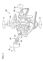
- an endoscope device 1 has an operating part 2 and a tubular insertion part 3 which extends from one end of the operating part 2 in a unitary manner.
- the insertion part 3 is elongated and has flexibility.
- the insertion part 3 has the same construction as an insertion part described in U.S. Patent Application No. 11/435,183 or U.S. Patent Application No. 11/652,880 . That is, the insertion part 3 has a sheath 4, a distal end construction part 7 which is disposed in the distal portion of the sheath 4, and bendable first and second arm members 5A and 5B which are provided on a distal end surface 7h of the distal end construction part 7 so as to protrude forward.
- Instrument channels 6 are formed inside the arm members 5A and 5B respectively, and extend to connect with a later-described connection sheath 20 via the insertion part 3 and operating part 2.
- Treatment tools 8A and 8B are inserted into the instrument channels 6 respectively, and treatment parts 9A and 9B of the treatment tools 8A and 8B protrude from the distal portions of the arm members 5A and 5B respectively. According to these treatment tools 8A and 8B, the first and second arm members 5A and 5B can perform treatment within the body cavity.
- a first bending part 11 and a second bending part 12 are formed in each arm member 5A and 5B in order from the distal side. Bending operation within the body cavity can be performed by moving the first and second bending parts 11 and 12 together with a third bending part 13 formed in the insertion part 3.
- An observation main body 14 for observing inside the body is disposed on the outer circumferential surface of the distal portion of the distal end construction part 7 so as to be capable of separating from the insertion part 3.
- the observation main body 14 is held by a holding mechanism 15.
- the first and second arm members 5A and 5B may be inserted into another sheath protruding from the distal end of the sheath 4, as described in U.S. Patent Application No. 11/652,880 .
- a forceps plug 16 is provided in the operating part 2 at the side surface of the one end portion connecting to the insertion part 3.
- the forceps plug 16 communicates with the instrument channels 6 formed within the sheath 4.
- a second treatment tool (not shown) from the forceps plug 16
- the second treatment tool can be protruded from the distal end of first or second arm member 5A or 5B.
- the operating part 2 is further provided with a switch 17, an angle knob 18, and a universal cable 19 which is connected to a control device or a monitor (not shown).
- the switch 17 is operated, for example, when feeding air or water, or aspirating through the instrument channel 6 formed within the insertion part 3.
- the angle knob 18 is used when bending the third bending part 13 in all directions with respect to the axis. An image observed by the observation main body 14 is transmitted to the monitor via the universal cable 19.
- the elongated and flexible connecting sheath 20 is provided so as to extend from the other end portion of the operating part 2.
- An operator 25 is provided at the end portion of the connection sheath 20.
- the operator 25 has a base 26 which fixes the connection sheath 20.
- a first operating unit 30A and a second operating unit 30B are attached with respect to the base 26.
- the first operating unit 30A has an operating stick 31A into which an operating part 10A of the treatment tool 8A inserted into the first arm member 5A is inserted.
- the operating part 10A is supported via the operating stick 31 A so as to freely advance and retract in the axial direction and to freely lean in all directions about the axis.
- the second operating unit 30B has an operating stick 31B into which an operating part 10B of the treatment tool 8B inserted into the first arm member 5B is inserted.
- the operating part 10B is supported via the operating stick 31B so as to freely advance and retract in the axial direction and to freely lean in all directions about the axis.
- the first rotation mechanism 3 2A rotates to the direction E1.
- the first bending part 11 of the first arm member 5A is bent to the direction F1 as shown in FIG 1 by an operating wire (not shown) wound on the first rotation mechanism 32A.
- the second rotation mechanism 33A rotates to the direction E2.
- the first bending part 11 of the first arm member 5A is bent to the direction F2 orthogonal to the direction F1 (i.e., the direction orthogonal to the sheet) by an operating wire (not shown) wound on the second rotation mechanism 33A.
- the first bending part 11 of the second arm member 5B is similarly bent when an operating stick 31B shown in FIG 2 is rotated.
- a gripping forceps is employed as the treatment tool 8A and an injection instrument is employed as the treatment tool 8B.
- the opening/closing operation of the distal portion of this gripping forceps is performed by moving a slider 35A with respect to a ring 34A in the axial direction to pull and push an operating wire (not shown) connected to the treatment part 9A.
- an operating wire not shown
- a slider 35 provided in the second operating unit 30 B is operated.
- a gripping forceps and an injection instrument are employed as the treatment tools 8A and 8B, this invention is not limited thereto and, for example, other treatment tools such as a high-frequency treatment tool, scissors, or a high-frequency snare may be employed.
- a first groove 7a is formed along the axis C1 of the insertion part 3 on the outer circumferential surface of the distal end construction part 7, and the observation main body 14 is disposed within the first groove 7a.
- the observation main body 14 houses a light receiving element such as a lens and a CCD, and connects to an observation cable 43 which transmits an image obtained by the observation main body 14 to the monitor.
- the observation cable 43 has a bending tendency and plays a role as an energizing member which energizes the observation main body 14 disposed in the first groove 7a toward the moving direction G1 opposite to the first and second arm members 5A and 5B in the radial direction of the insertion part 3.
- the observation cable 43 is guided by a guide hole (not shown) communicating from the distal end construction part 7 of the insertion part 3 to the operating part 2.
- the opposite side of the first and second arm members 5A and 5B in the radial direction of the insertion part 3 means a symmetrical side with the midpoint P between the positions where the first and second arm members 5A and 5B are provided on the distal end surface 7h of the distal end construction part 7, with respect to the axis C1.
- a second groove 7b is formed along the circumferential direction on the outer circumferential surface of the distal end construction part 7, and a curved plate-shaped open/close member 41 is supported by the second groove 7b so as to freely move along the circumferential direction of the distal end construction part 7.
- the open/close member 41 is set such that, when moving to one side of the second groove 7b, the open/close member 41 resists the energizing force by the observation cable 43 to hold the observation main body 14 in a state where the observation main body 14 is disposed within the first groove 7a, and, when moving from the position shown in FIG 4 to the other side of the second groove 7b, the holding state of the observation main body 14 is released.
- Both end portions of the open/close member 41 are connected to an open/close member driving wire 44.
- the open/close member driving wire 44 is guided by the guide hole (not shown) communicating from the distal end construction part 7 of the insertion part 3 to the operating part 2, and is operated by an observation main body operating lever (not shown) provided in the operating part 2.
- the open/close member 41 and the open/close member driving wire 44 constitute the above-described holding mechanism 15.
- the operating lever is pushed such that the first and second arm members 5A and 5B are parallel to each other.
- the treatment tools 8A and 8B are pulled with respect to the operating parts 10A and 10B to make the treatment parts 9A and 9B be in a state where the treatment parts 9A and 9B do not protrude from the distal ends of the arm members 5A and 5B.
- the periphery is observed by the observation main body 14, and the insertion part 3 is inserted into the body cavity of the subject while bending the first bending portions 11 of the arm members 5A and 5B by using the first and second operating units 30A and 30B respectively and bending the third bending part 13 by using the angle knob 18.
- the insertion part 3 is fixed in a state where the distal portions of the two arm members 5A and 5B are opposed to the affected area.
- the treatment tools 8A and 8B are pushed with respect to the operating parts 10A and 10B such that the treatment parts 9A and 9B of the treatment tools 8A and 8B are protruded from the distal ends of the arm members 5A and 5B as shown in FIG. 4 .
- the second bending parts 12 are fixed in a bending state where the first and second arm members 5A and 5B are separated from each other.
- the open/close member 41 is moved to the other side of the second groove 7b to release the holding state of the observation main body 14.
- the observation cable 43 energizes the observation main body 14 disposed in the first groove 7a toward the moving direction G1
- the observation main body 14 is moved to a position separating from the distal end construction part 7 while maintaining the posture of the observation main body 14.
- the affected area is grasped by the treatment part 9A by rotating the operating stick 31A to bend the first bending part 11 of the first arm member 5A and by moving the slider 35A. Then, the needle-shaped treatment part 9B is pricked into the affected area while bending the first bending part 11 of the second arm member 5B by rotating the operating stick 31B, and the drug solution or the like (not shown) is injected into the affected area by moving the slider 35B.
- the operating lever is pushed such that the first and second arm members 5A and 5B are parallel to each other.
- the treatment tools 8A and 8B are pulled with respect to the operating parts 10A and 10B to make the treatment parts 9A and 9B in a state where the treatment parts 9A and 9B do not protrude from the distal ends of the arm members 5A and 5B.
- the observation main body 14 is housed within the sheath 4 by pulling the observation cable 43 toward the proximal end. After making the insertion part 3 in this state, the insertion part 3 is pulled toward the proximal end so as to be pulled out from the body cavity.
- the first and second arm members 5A and 5B are provided on the distal end surface 7h of the distal end construction part 7, and the observation main body 14 is disposed within the first groove 7a. Therefore, since the outer diameter of the insertion part 3 including the arm members 5A and 5B can be reduced, the depression of the insertion ability of the insertion part 3 when inserting the insertion part 3 into the body cavity of the subject can be prevented.
- the treatment parts 9A and 9B can be observed from the skew direction, not from the proximal side of the first and second arm members 5A and 5B.
- the observation main body 14 since it can be prevented that the field of view via the observation main body 14 is interrupted by the proximal portions of the first and second arm members 5A and 5B when performing treatment, visibility of the treatment parts 9A and 9B can be improved.
- the distance from the treatment parts 9A and 9B to the observation main body 14 can be elongated, the range of view of the treatment parts 9A and 9B via the observation main body 14 can be enlarged. As a result, the treatment of the affected area can be securely performed in brief time.
- an endoscope device 55 of the present modification example is provided with a moving mechanism 50 which moves the observation main body 14.
- the moving mechanism 50 has a pair of link members 53 which are symmetrically disposed so as to sandwich the observation main body 14 therebetween with one end portion of the link member 53 rotatively supported to the observation main body 14 by a first pin 51, and the other end portion of the link member 53 rotatively supported to the insertion part 3 by a second pin 52.
- the second pin 52 is disposed such that the axis of the second pin 52 is positioned closer to the axis C1 than the axis of the first pin 51.
- An observation cable 54 of the present modification example does not have a bending tendency.
- the treatment method of the present modification example is basically the same as that of the first embodiment.
- the observation cable 54 inserted into a guide hole (not shown) is moved toward the proximal end by pulling the observation cable 54 toward the proximal end at the operating part 2 after the second bending parts 12 of the first and second arm members 5A and 5B are fixed in a bending state.
- the observation main body 14 is moved to a position separating from the distal end construction part 7 by rotating the pair of the link members 53 around the second pin 52.
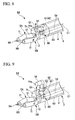
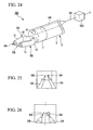
- an endoscope device 64 of the present embodiment is provided with an extension/contraction mechanism 60 which moves the observation main body 14 toward the moving direction G1 opposite to the first and second arm members 5A and 5B in the radial direction.
- the extension/contraction mechanism 60 has a telescopic portion 62 formed by nesting a plurality of cylindrical members 61 having diameters different from each other such that the entirety of the telescopic portion 62 freely extends and contracts in the moving direction G1, and an operating wire 63 which protrudes and retracts the telescopic portion 62 in the moving direction G1 by pushing and pulling the proximal portion of the operating wire 63.
- the distal end surface 7h of the distal end construction part 7 and a distal end surface 14a of the observation main body 14 be coplanar.
- the treatment method of the present embodiment is basically the same as that of the first embodiment. However, in the present embodiment, as shown in FIG. 9 , the observation main body 14 is moved toward the moving direction G1 so as to separate from the distal end construction part 7 by pushing the proximal portion of the operating wire 63 after the second bending parts 12 of the first and second arm members 5A and 5B are fixed in a bending state respectively.
- the treatment parts 9A and 9B can be observed from the slew direction, not from the proximal side of the first and second arm members 5A and 5B.
- the observation main body 14 since it can be prevented that the field of view via the observation main body 14 is interrupted by the proximal portions of the first and second arm members 5A and 5B when performing treatment, visibility of the treatment parts 9A and 9B can be improved.
- an endoscope device 73 of the present modification example is provided with an extension/contraction mechanism 70 which moves the observation main body 14 toward the moving direction G1 opposite to the first and second arm members 5A and 5B in the radial direction.
- the extension/contraction mechanism 70 has an accordion member 71 formed so as to freely extend and contract in the moving direction G1, and an air pipe 72 connected to an air feeding/exhausting device (not shown) for feeding air to the accordion member 71 and exhausting air from the accordion member 71.
- the observation cable 54 is connected to the monitor via the accordion member 71, the insertion part 3, and the universal cable 19.
- the treatment method of the present modification example is basically the same as that of the first embodiment. However, in the present modification example, as shown in FIG 11 , after the second bending parts 12 of the first and second arm members 5A and 5B are fixed in a bending state respectively, the observation main body 14 is moved to a position separating from the axis C1 while maintaining the posture of the observation main body 14 by feeding air to the accordion member 71 via the air pipe 72 by using the air feeding/exhausting device.
- an endoscope device 86 of the present embodiment is provided with an observation main body 14 which observes the direction to which the observation main body faces, an observation main body rotation mechanism 80 which rotatively supports the observation main body 14 such that the observation main body 14 faces the moving direction G1 opposite to the first and second arm members 5A and 5B in the radial direction and faces the front of the insertion part 3, and a reflection member 81 disposed in the distal portion of the insertion part 3 so as to freely protrude and retract.
- the observation main body 14 is supported in the distal end construction part 7 by a pin 82 so as to freely rotate around the direction crossing the axis C1.
- a first wire 83 is fixed to the proximal surface of the observation main body 14 and a second wire 84 is fixed to the side surface of the observation main body 14.
- the first and second wires 83 and 84 are inserted into the insertion part 3 through a wire guide hole 7c formed in the distal end construction part 7, and are fixed to an operating lever (not shown) provided in the operating part 2. By rotating the operating lever, either of the first or second wire 83 or 84 is pulled.
- Two tube-shaped support members 85 are provided such that one end each thereof is fixed to the reflection member 81 and the other ends thereof are moved within reflection member guide holes 7d formed in the distal end construction part 7.
- a pinion gear (not shown) fixed to the observation main body 14 so as to be coaxial with the pin 82 and a rack gear (not shown) formed in the support member 85, the observation main body 14 and the reflection member 81 move together as follows.
- the reflection member 81 protrudes so as to reflect an image of the treatment tools 8A and 8B onto the observation main body 14 when the observation main body 14 faces the moving direction G1 opposite to the first and second arm members 5A and 5B in the radial direction, and the reflection member 81 is moved toward the distal portion of the insertion part 3 when the observation main 14 faces the front of the insertion part 3.
- the pin 82, the first wire 83, the second wire 84, and the operating lever constitute the above-described observation main body rotation mechanism 80.
- the image which is reflected by the reflection member 81 and then is observed by using the observation main body 14 be vertically inverted to be displayed on the monitor.
- the treatment method of the present embodiment is basically the same as that of the first embodiment.
- the insertion part 3 is inserted into the body cavity in a state where the observation main 14 faces the front and is moved toward the distal portion of the insertion part 3 so as to be housed within the insertion part 3.
- the observation main body 14 is turned to face the moving direction G1 by rotating the operating lever to pull the second wire 84 after the second bending parts 12 of the first and second arm members 5A and 5B are fixed in a bending state.
- the reflection member 81 is protruded so as to reflect the image of the treatment tools 8A and 8B onto the observation main body 14.
- the observation main body 14 can obtain the image of the treatment parts 9A and 9B reflected by the reflection member 81, which is an image seen from the direction more skewed with respect to the axis C1 than a direct image from the treatment parts 9A and 9B to the observation main body 14. Therefore, since the image obtained by the observation main body 14 being interrupted by the proximal portions of the first and second arm members 5A and 5B can be prevented, visibility of the treatment parts 9A and 9B can be improved.
- the observation main body 14 may be fixed to the first groove 7a of the distal end construction part 7, and the two support members 85 may be provided such that one end each thereof is fixed to the reflection member 81, the other ends thereof are rotatively fixed to the distal end construction part 7, and substantially center portions thereof are fixed to distal ends of a pair of operating wires 87.
- the observation main body 14 can observe not only the direct image from the treatment parts 9A and 9B to the observation main body 14 but also the image which is once reflected by the reflection member 81 and then proceeds to the observation main body 14. Therefore, the treatment parts 9A and 9B can be observed from two angles at once by using the observation main body 14.
- an endoscope 94 of the present embodiment is provided with an observation main body rotation mechanism 90 which rotates the observation main body 14 around the rotational axis C2 crossing the axis C1 of the insertion part 3 so as to make the distal portions of the first and second arm members 5A and 5B (i.e., the treatment parts 9A and 9B) positioned in the center of view via the observation main body 14.
- an observation main body rotation mechanism 90 which rotates the observation main body 14 around the rotational axis C2 crossing the axis C1 of the insertion part 3 so as to make the distal portions of the first and second arm members 5A and 5B (i.e., the treatment parts 9A and 9B) positioned in the center of view via the observation main body 14.
- the observation main body 14 is supported by a pin 91 within a hole 7e formed in the distal end construction part 7 along the axis C1 so as to freely rotate about the rotational axis C2.
- One end of the proximal surface of the observation main body 14 is fixed to a first wire 92 and the other end of the proximal end surface of the observation main body 14 is fixed to a second wire 93 so as to sandwich the rotational axis C2.
- the first and second wires 92 and 93 are inserted into the insertion part 3 and are fixed to an operating wire (not shown) provided in the operating part 2. By rotating the operating lever, either of the first or second wire 92 or 93 is pulled.
- the treatment method of the present embodiment is basically the same as that of the first embodiment However, in the present embodiment, after the second bending parts 12 of the first and second arm members 5A and 5B are fixed in a bending state, the treatment is performed while rotating the observation main body 14 about the rotational axis C2 by rotating the operating lever to adjust the view via the observation main body 14.
- the endoscope device 94 of the present embodiment it is possible to make the treatment parts 9A and 9B positioned in the center of view via the observation main body 14 by rotating the observation main body 14 about the rotational axis C2 crossing the axis C1. As a result, it is possible to adjust the view via the observation main body 14 such that the operator easily observes.
- an endoscope device 103 of the present embodiment is provided with an observation main body moving mechanism 100 which moves the observation main body 14 in the moving direction G2 parallel to an arm plane S on which the arm members 5A and 5B are attached, so as to position the distal portions of the first arid second arm members 5A and 5B (i.e., the treatment parts 9A and 9B) in the center of view via the observation main body 14.
- the arm plane S on which the arm members 5A and 5B are attached is a plane which includes positions where the arm members 5A and 5B are provided on the distal end surface 7h of the distal end construction part 7 and which is parallel to the axis C1.
- a first long hole 7f is formed on the distal end surface 7h of the distal end construction part 7 along the moving direction G2 in which the observation main body 14 moves, and a second long hole 7g is formed on the side surface of the distal end construction part 7 so as to be parallel to the moving direction G2.
- the first and second long holes 7f and 7g communicate with each other inside the distal end construction part 7.
- the observation main body 14 is provided in the first long hole 7h with a protrude portion 14b formed in the observation main body 14 engaged with the second long hole 7g such that the observation main body 14 is able to move only in the moving direction G2.
- a distal end of a first wire 101 is fixed to the surface of one side of the protrude portion 14b in the moving direction G2, and a distal end of a second wire 102 is fixed to the surface of the other side of the protrude portion 14b.
- the first and second wires 101 and 102 are inserted into the insertion part 3 and are fixed to an operating wire (not shown) provided in the operating part 2. By rotating the operating lever, either of the first or second wire 101 or 102 is pulled.
- the treatment method of the present embodiment is basically the same as that of the first embodiment. However, in the present embodiment, after the second bending parts 12 of the first and second arm members 5A and 5B are fixed in a bending state, the treatment is performed while moving the observation main body 14 in the moving direction G2 by rotating the operating lever to adjust the view via the observation main body 14.
- the endoscope device 103 of the present embodiment it is possible to make the treatment parts 9A and 9B positioned in the center of view via the observation main body 14 by moving the observation main body 14 in the moving direction G2. As a result, it is possible to adjust the view via the observation main body 14 such that the operator easily observes.
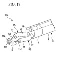
- an endoscope device 113 of the present embodiment is provided with a reflection member 110 in the first arm member 5A which reflects the image of a desired site K such as an affected area toward the observation main body 14.
- the reflection member 110 is provided with a mirror 111 which reflects a light.
- the reflection member 110 is provided in the treatment part 9A of the treatment tool 8A in the present embodiment, the reflection member 110 may be provided in the distal portion of the first arm member 5A.
- a gripping forceps is employed as a treatment tool 112.
- the treatment method of the present embodiment is basically the same as that of the first embodiment. However, in the present embodiment, after the second bending parts 12 of the first and second arm members 5A and 5B are fixed in a bending state, the reflection member 110 is moved to a position to be observed in the vicinity of the desired site K while bending the first bending part 11 of the first arm member 5A by rotating the operating stick 31A. Then, the desired site K is removed by the treatment tool 112 by moving the slider 35B while bending the first bending part 11 of the second arm member 5B by rotating the operating stick 31B.
- the desired site K and the vicinity thereof can be observed by changing the direction of the reflection member 110 or moving the reflection member 110 in order to easily observe the desired site K. Furthermore, the condition and the treatment state of the desired site K can be observed more precisely from two directions.
- the reflection member 110 is provided only in the first arm member 5A in the present invention, the reflection member 110 may be provided only in the second arm member 5B and the reflection members 110 may be provided in both of the first and second arm members 5A and 5B.
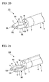
- an endoscope device 121 of the present modification example is provided with a sub-observation main body 120 in the distal end surface 7h of the distal end construction part 7 at a position opposite to the observation main body 14 with respect to the first and second arm members 5A and 5B.
- the sub-observation main body 120 houses a light receiving element such as a lens and a CCD and connects to a sub-observation cable (not shown) which transmits an image obtained by the sub-observation main body 120 to the monitor.
- the monitor is constructed such that the displayed image can be switched between an image obtained by the observation main body and an image obtained by the sub-observation main body 120 while observing the position of the treatment parts 9A and 9B or the first and second arm members 5A and 5B.
- the treatment tools 9A and 9B can be observed from the two directions by using the observation main body 14 and the sub-observation main body 120, visibility of the treatment parts 9A and 9B can be improved.
- sub-endoscopes 130 and 131 are inserted into the instrument channels 6 of the first and second arm members 5A and 5B respectively. Images obtained from the sub-endoscopes 130 and 131 are transmitted to the monitor via sub-endoscope cables (not shown).
- the monitor is constructed so as to switch between the states such as where only an image obtained by the observation main body 14 is displayed or where images obtained not only by the observation main body but also by the sub-endoscopes 130 and 131 are displayed all together.
- the sub-endoscopes 130 and 131 can be exchanged for treatment tools such as a gripping forceps and an injection instrument if necessary.
- the endoscope device 132 of the present modification example since the treatment tools 9A and 9B can be observed from the three directions by using the observation main body 14, the sub-endoscope 130, and the sub-endoscope 131, visibility of the treatment parts 9A and 9B and the arm members 5A and 5B can be improved.
- a sub-channel 6B is formed in the insertion part 3, and a sub-endoscope 140 the distal portion of which is bendable is inserted into the sub-channel 6B so as to freely advance and retract in the direction of the axis C1.
- An image obtained by the sub-endoscope 140 is transmitted to the monitor via a sub-endoscope cable (not shown).
- the monitor is constructed so as to switch between the states such as where only an image obtained by the observation main body 14 is displayed or where images obtained not only by the observation main body but also by the sub-endoscope 140 are displayed all together.
- the endoscope device 141 of the present modification example since the treatment tools 9A and 9B can be observed by using the observation main body 14 and the sub-endoscope 140, visibility of the treatment parts 9A and 9B can be improved. Furthermore, since the sub-endoscope 140 is formed such that the distal portion thereof is bendable and freely advances and retracts in the direction of the axis C1, visibility of the treatment parts 9A and 9B can be improved higher.
- a sub-endoscope 150 which observes in a front diagonal direction is provided on the outer circumferential surface of the distal end construction part 7.
- An image obtained by the sub-endoscope 150 is transmitted to the monitor via a sub-endoscope cable (not shown).
- the monitor is constructed so as to switch between the states such as where only an image obtained by the observation main body 14 is displayed or where images obtained not only by the observation main body but also by the sub-endoscope 150 are displayed all together.
- the treatment tools 9A and 9B can be observed by using the observation main body 14 and the sub-endoscope 150, field of view can be increased and visibility of the treatment parts 9A and 9B can be improved.
- an endoscope device 161 of the present embodiment is provided with an image processor 160 which extracts an image showing the distal portions of the first and second arm members 5A and 5B (i.e., the treatment parts 9A and 9B) and the vicinity thereof from an image obtained by the observation main body 14, and a not-shown monitor (display portion) which magnifies and displays the image extracted by the image processor 160.
- the treatment parts 9A and 9B and the arm members 5A and 5B be painted a color having less redness.
- the image processor 160 has functions such as extracting a specified color in an image captured by the observation main body 14, binarizing the brilliances of the light based on a properly determined threshold, and extracting the outline of a specified color in the image to recognize the distal portions.
- the red light is extracted in an image (shown in FIG. 25 ) captured by the observation main body 14 to measure brilliances of the red light, and then the brilliances are binarized based on a properly determined threshold since the tissues inside the body cavity have a reddish color.
- the shapes of the treatment tools 9A and 9B can be extracted from the tissue image such that, for example, the tissue is colored black and the treatment parts 9A and 9B are colored white.
- shapes of the outline of the black portion and white portion are extracted, and then positions where the direction of the shape of the outline changes by more than a predetermined value are detected as the position of the treatment parts 9A and 9B.
- the treatment parts 9A and 9B can be magnified and then displayed on the monitor, visibility of the treatment parts 9A and 9B can be improved.
- a mechanism for optically magnifying an image may be housed within the observation main body 14.
- an endoscope device180 of the present embodiment is provided with a channel 172 formed in the distal end construction part 7, and an observation mechanism 173 the distal portion of which is bendable and which is inserted into the channel 172.
- the distal portion of the channel 172 is communicated both with a first opening 170 formed on the distal end surface 7h of the distal end construction part 7 and with a second opening 171 formed on the side surface of the distal end construction part 7.
- the observation mechanism 173 is capable of observation from the first opening 170 and the second opening 171.
- the distal portion of the observation mechanism 173 is bendable by an operating wire (not shown) provided inside thereof.
- the second opening 171 open toward a front diagonal direction of the distal end construction part 7.
- the insertion part 3 is inserted into the body cavity of the subject while observing the front of the insertion part 3 with the observation mechanism 173 straight and inserted into the first opening 170.
- the treatment is performed in a state where the observation mechanism 173 is inserted into the first opening 170 with the arm members 5A and 5B extending forward.
- the observation mechanism 173 When the treatment is performed at the outside in the radial direction of the distal end construction part 7, as shown in FIG 28 , the observation mechanism 173 is once pulled back to the communicating portion of the first opening 170 and the second opening 171 and then is pushed toward the distal side with the distal portion of the observation mechanism 173 bent toward the second opening 171. Then, the arm members 5A and 5B are bent toward the second opening 171 and the treatment is performed by the arm members 5A and 5B while observing by the observation mechanism 173 from the second opening 171 side.
- the endoscope device 174 of the present embodiment since it is possible to observe by using the observation mechanism 173 not only the front of the distal end construction part 7 but also the outside in the radial direction of the distal end construction part 7, the observable area of the treatment parts 9A and 9B by using the one observation mechanism 173 can be expanded.
- Known endoscopes may be employed as the observation mechanism 173.
- the observation main body 14 is not provided in an endoscope device 180.
- a known endoscope N1 which is not provided with a treatment part is used with the endoscope N1 attached to a cylindrical guide member 181 provided at the distal end construction part 7 of the endoscope device 180.
- the endoscope device 180 may be inserted into the body cavity of the subject such that the endoscope N1 is inserted into the body cavity in advance, and then the endoscope device 180 is inserted by moving the guide member 181 along an insertion part N2 of the endoscope N1.
- the endoscope device 180 may be attached to an endoscope N4 provided with a treatment part N3.
- the treatment can be performed while observing forward with a known endoscope instead of the observation main body 14.
- an endoscope device 193 is provided with the observation main body 14 disposed so as to freely separate from the distal end construction part 7, an attachment member 190 provided in the observation main body 14 for attaching the observation main body 14 to the inner wall B of the body cavity such as the abdominal wall in a freely attaching and detaching manner, and a treatment tool 191 for attachment inserted into the first arm member 5A.
- the treatment tool 191 for attachment is capable of attaching the observation main body 14 to the inner wall B of the body cavity by the attachment member 190 by engaging with the observation main body 14 disposed in the distal end construction part 7.
- a clip which has a spring and grasps the inner wall B of the body cavity is employed as the attachment member 190 in the present embodiment
- a hook, a magnet or the like may be employed as long as it can attach the observation main body 14 to the inner wall B of the body cavity.
- a cable 192 connects the observation main body 14 and the insertion part 3.
- the observation main body 14 is hosed within the first groove 7a by reeling up the cable 192 by using a reeling mechanism (not shown) provided in the proximal portion of the cable 192.
- the treatment method of the present embodiment is basically the same as that of the first embodiment. However, in the present embodiment, after the insertion part 3 is inserted into the body cavity with the two arm members 5A and 5B opposed to the affected area, the first bending part 11 of the first arm member 5A is bent such that the treatment tool 191 for attachment is engaged with the observation main body 14. Then, the observation main body 14 is attached to the inner wall B of the body cavity by the attachment member 190 while extending the cable 192.
- the treatment parts 9A and 9B can be observed from the skew direction, not from the proximal side of the first and second arm members 5A and 5B.
- the observation main body 14 since it can be prevented that the field of view via the observation main body 14 is interrupted by the proximal portions of the first and second arm members 5A and 5B when performing the treatment, visibility of the treatment parts 9A and 9B can be improved.
- first and second arm members 5A and 5B are provided in the distal end surface 7h of the distal end construction part 7 in the first through ninth embodiments and the modification examples thereof, for example, the first and second arm members 5A and 5B may be provided in the side surface of the distal end construction part 7.
- the two first and second arm members 5A and 5B are provided in the distal end surface 7h of the distal end construction part 7 in the first through forth embodiments, the sixth through ninth embodiments, and the modification examples thereof, for example, three or more arm members may be provided.
Landscapes
- Health & Medical Sciences (AREA)
- Life Sciences & Earth Sciences (AREA)
- Surgery (AREA)
- General Health & Medical Sciences (AREA)
- Public Health (AREA)
- Veterinary Medicine (AREA)
- Nuclear Medicine, Radiotherapy & Molecular Imaging (AREA)
- Animal Behavior & Ethology (AREA)
- Molecular Biology (AREA)
- Engineering & Computer Science (AREA)
- Biomedical Technology (AREA)
- Heart & Thoracic Surgery (AREA)
- Medical Informatics (AREA)
- Biophysics (AREA)
- Radiology & Medical Imaging (AREA)
- Physics & Mathematics (AREA)
- Pathology (AREA)
- Optics & Photonics (AREA)
- Endoscopes (AREA)
- Instruments For Viewing The Inside Of Hollow Bodies (AREA)
Applications Claiming Priority (1)
| Application Number | Priority Date | Filing Date | Title |
|---|---|---|---|
| US12/123,742 US8562513B2 (en) | 2008-05-20 | 2008-05-20 | Endoscope device |
Publications (2)
| Publication Number | Publication Date |
|---|---|
| EP2123225A1 true EP2123225A1 (de) | 2009-11-25 |
| EP2123225B1 EP2123225B1 (de) | 2014-12-17 |
Family
ID=40886804
Family Applications (1)
| Application Number | Title | Priority Date | Filing Date |
|---|---|---|---|
| EP09006717.4A Not-in-force EP2123225B1 (de) | 2008-05-20 | 2009-05-19 | Endoskopvorrichtung |
Country Status (3)
| Country | Link |
|---|---|
| US (1) | US8562513B2 (de) |
| EP (1) | EP2123225B1 (de) |
| JP (1) | JP5325654B2 (de) |
Cited By (10)
| Publication number | Priority date | Publication date | Assignee | Title |
|---|---|---|---|---|
| WO2013071938A1 (en) | 2011-11-16 | 2013-05-23 | Coloplast A/S | Operation device especially intended for proceeding to an operation inside the body of a living being |
| EP2606812A1 (de) * | 2011-12-23 | 2013-06-26 | Covidien LP | Vorrichtung für endoskopische Verfahren |
| US8647258B2 (en) | 2008-01-10 | 2014-02-11 | Covidien Lp | Apparatus for endoscopic procedures |
| US8771169B2 (en) | 2008-01-10 | 2014-07-08 | Covidien Lp | Imaging system for a surgical device |
| WO2015009949A2 (en) | 2013-07-17 | 2015-01-22 | Board Of Regents Of The University Of Nebraska | Robotic surgical devices, systems and related methods |
| CN104470459A (zh) * | 2012-08-30 | 2015-03-25 | 奥林巴斯株式会社 | 医疗用系统和操作方法 |
| CN104814792A (zh) * | 2015-04-01 | 2015-08-05 | 上海交通大学 | 可分离多臂软体机械臂装置 |
| CN106456201A (zh) * | 2014-06-19 | 2017-02-22 | 奥林巴斯株式会社 | 钳子装置和手术系统 |
| DE102016216160A1 (de) | 2015-09-03 | 2017-03-09 | Richard Wolf Gmbh | Schaftinstrument, insbesondere medizinisch-endoskopisches Schaftinstrument |
| USD798443S1 (en) | 2016-05-03 | 2017-09-26 | Coloplast A/S | Videoscope handle |
Families Citing this family (81)
| Publication number | Priority date | Publication date | Assignee | Title |
|---|---|---|---|---|
| US8992420B2 (en) * | 2004-04-14 | 2015-03-31 | Usgi Medical, Inc. | Methods and apparatus for off-axis visualization |
| US7655004B2 (en) | 2007-02-15 | 2010-02-02 | Ethicon Endo-Surgery, Inc. | Electroporation ablation apparatus, system, and method |
| US8075572B2 (en) | 2007-04-26 | 2011-12-13 | Ethicon Endo-Surgery, Inc. | Surgical suturing apparatus |
| US8100922B2 (en) | 2007-04-27 | 2012-01-24 | Ethicon Endo-Surgery, Inc. | Curved needle suturing tool |
| US8262655B2 (en) | 2007-11-21 | 2012-09-11 | Ethicon Endo-Surgery, Inc. | Bipolar forceps |
| US8568410B2 (en) | 2007-08-31 | 2013-10-29 | Ethicon Endo-Surgery, Inc. | Electrical ablation surgical instruments |
| US8579897B2 (en) | 2007-11-21 | 2013-11-12 | Ethicon Endo-Surgery, Inc. | Bipolar forceps |
| US8480657B2 (en) | 2007-10-31 | 2013-07-09 | Ethicon Endo-Surgery, Inc. | Detachable distal overtube section and methods for forming a sealable opening in the wall of an organ |
| US20090112059A1 (en) | 2007-10-31 | 2009-04-30 | Nobis Rudolph H | Apparatus and methods for closing a gastrotomy |
| US8262680B2 (en) | 2008-03-10 | 2012-09-11 | Ethicon Endo-Surgery, Inc. | Anastomotic device |
| US8317806B2 (en) | 2008-05-30 | 2012-11-27 | Ethicon Endo-Surgery, Inc. | Endoscopic suturing tension controlling and indication devices |
| US8070759B2 (en) | 2008-05-30 | 2011-12-06 | Ethicon Endo-Surgery, Inc. | Surgical fastening device |
| US8114072B2 (en) | 2008-05-30 | 2012-02-14 | Ethicon Endo-Surgery, Inc. | Electrical ablation device |
| US8652150B2 (en) | 2008-05-30 | 2014-02-18 | Ethicon Endo-Surgery, Inc. | Multifunction surgical device |
| US8771260B2 (en) | 2008-05-30 | 2014-07-08 | Ethicon Endo-Surgery, Inc. | Actuating and articulating surgical device |
| US8679003B2 (en) | 2008-05-30 | 2014-03-25 | Ethicon Endo-Surgery, Inc. | Surgical device and endoscope including same |
| US8906035B2 (en) | 2008-06-04 | 2014-12-09 | Ethicon Endo-Surgery, Inc. | Endoscopic drop off bag |
| US8403926B2 (en) | 2008-06-05 | 2013-03-26 | Ethicon Endo-Surgery, Inc. | Manually articulating devices |
| US8361112B2 (en) | 2008-06-27 | 2013-01-29 | Ethicon Endo-Surgery, Inc. | Surgical suture arrangement |
| US8262563B2 (en) | 2008-07-14 | 2012-09-11 | Ethicon Endo-Surgery, Inc. | Endoscopic translumenal articulatable steerable overtube |
| US8888792B2 (en) | 2008-07-14 | 2014-11-18 | Ethicon Endo-Surgery, Inc. | Tissue apposition clip application devices and methods |
| US8211125B2 (en) | 2008-08-15 | 2012-07-03 | Ethicon Endo-Surgery, Inc. | Sterile appliance delivery device for endoscopic procedures |
| US8529563B2 (en) | 2008-08-25 | 2013-09-10 | Ethicon Endo-Surgery, Inc. | Electrical ablation devices |
| US8241204B2 (en) | 2008-08-29 | 2012-08-14 | Ethicon Endo-Surgery, Inc. | Articulating end cap |
| US8480689B2 (en) | 2008-09-02 | 2013-07-09 | Ethicon Endo-Surgery, Inc. | Suturing device |
| US8409200B2 (en) | 2008-09-03 | 2013-04-02 | Ethicon Endo-Surgery, Inc. | Surgical grasping device |
| US8114119B2 (en) | 2008-09-09 | 2012-02-14 | Ethicon Endo-Surgery, Inc. | Surgical grasping device |
| US8337394B2 (en) | 2008-10-01 | 2012-12-25 | Ethicon Endo-Surgery, Inc. | Overtube with expandable tip |
| US8157834B2 (en) | 2008-11-25 | 2012-04-17 | Ethicon Endo-Surgery, Inc. | Rotational coupling device for surgical instrument with flexible actuators |
| US8172772B2 (en) | 2008-12-11 | 2012-05-08 | Ethicon Endo-Surgery, Inc. | Specimen retrieval device |
| US8361066B2 (en) | 2009-01-12 | 2013-01-29 | Ethicon Endo-Surgery, Inc. | Electrical ablation devices |
| US8828031B2 (en) | 2009-01-12 | 2014-09-09 | Ethicon Endo-Surgery, Inc. | Apparatus for forming an anastomosis |
| US8252057B2 (en) | 2009-01-30 | 2012-08-28 | Ethicon Endo-Surgery, Inc. | Surgical access device |
| US9226772B2 (en) | 2009-01-30 | 2016-01-05 | Ethicon Endo-Surgery, Inc. | Surgical device |
| US8037591B2 (en) | 2009-02-02 | 2011-10-18 | Ethicon Endo-Surgery, Inc. | Surgical scissors |
| CN102573602B (zh) * | 2009-08-27 | 2015-04-01 | 纳维瑞士股份公司 | 内窥镜及其使用方法 |
| US20110098704A1 (en) | 2009-10-28 | 2011-04-28 | Ethicon Endo-Surgery, Inc. | Electrical ablation devices |
| US8888687B2 (en) * | 2009-10-28 | 2014-11-18 | Boston Scientific Scimed, Inc. | Method and apparatus related to a flexible assembly at a distal end portion of a medical device |
| US8608652B2 (en) | 2009-11-05 | 2013-12-17 | Ethicon Endo-Surgery, Inc. | Vaginal entry surgical devices, kit, system, and method |
| US20110152610A1 (en) * | 2009-12-17 | 2011-06-23 | Ethicon Endo-Surgery, Inc. | Intralumenal accessory tip for endoscopic sheath arrangements |
| US8353487B2 (en) | 2009-12-17 | 2013-01-15 | Ethicon Endo-Surgery, Inc. | User interface support devices for endoscopic surgical instruments |
| US8496574B2 (en) | 2009-12-17 | 2013-07-30 | Ethicon Endo-Surgery, Inc. | Selectively positionable camera for surgical guide tube assembly |
| US8506564B2 (en) | 2009-12-18 | 2013-08-13 | Ethicon Endo-Surgery, Inc. | Surgical instrument comprising an electrode |
| US9028483B2 (en) | 2009-12-18 | 2015-05-12 | Ethicon Endo-Surgery, Inc. | Surgical instrument comprising an electrode |
| US9005198B2 (en) | 2010-01-29 | 2015-04-14 | Ethicon Endo-Surgery, Inc. | Surgical instrument comprising an electrode |
| TWI409048B (zh) * | 2010-06-11 | 2013-09-21 | 具有高活動自由度之內視裝置及其運作方法 | |
| CN103209650B (zh) * | 2010-09-20 | 2016-06-08 | 脊柱诊察公司 | 套管式切开器 |
| US20120095498A1 (en) * | 2010-10-13 | 2012-04-19 | Ethicon Endo-Surgery, Inc. | Methods and devices for mechanical space creation at a surgical site |
| US10092291B2 (en) | 2011-01-25 | 2018-10-09 | Ethicon Endo-Surgery, Inc. | Surgical instrument with selectively rigidizable features |
| US9233241B2 (en) | 2011-02-28 | 2016-01-12 | Ethicon Endo-Surgery, Inc. | Electrical ablation devices and methods |
| US9314620B2 (en) | 2011-02-28 | 2016-04-19 | Ethicon Endo-Surgery, Inc. | Electrical ablation devices and methods |
| US9254169B2 (en) | 2011-02-28 | 2016-02-09 | Ethicon Endo-Surgery, Inc. | Electrical ablation devices and methods |
| CN203468565U (zh) * | 2011-03-10 | 2014-03-12 | 松下电器产业株式会社 | 内窥镜摄像机及内窥镜装置 |
| US9049987B2 (en) | 2011-03-17 | 2015-06-09 | Ethicon Endo-Surgery, Inc. | Hand held surgical device for manipulating an internal magnet assembly within a patient |
| WO2013048595A1 (en) | 2011-06-10 | 2013-04-04 | Board Of Regents Of The University Of Nebraska | Methods, systems, and devices relating to surgical end effectors |
| CA3082073C (en) | 2011-07-11 | 2023-07-25 | Board Of Regents Of The University Of Nebraska | Robotic surgical devices, systems, and related methods |
| US8986199B2 (en) | 2012-02-17 | 2015-03-24 | Ethicon Endo-Surgery, Inc. | Apparatus and methods for cleaning the lens of an endoscope |
| CA2871149C (en) | 2012-05-01 | 2020-08-25 | Board Of Regents Of The University Of Nebraska | Single site robotic device and related systems and methods |
| US9427255B2 (en) | 2012-05-14 | 2016-08-30 | Ethicon Endo-Surgery, Inc. | Apparatus for introducing a steerable camera assembly into a patient |
| US9078662B2 (en) | 2012-07-03 | 2015-07-14 | Ethicon Endo-Surgery, Inc. | Endoscopic cap electrode and method for using the same |
| US9545290B2 (en) | 2012-07-30 | 2017-01-17 | Ethicon Endo-Surgery, Inc. | Needle probe guide |
| US9572623B2 (en) | 2012-08-02 | 2017-02-21 | Ethicon Endo-Surgery, Inc. | Reusable electrode and disposable sheath |
| US10314649B2 (en) | 2012-08-02 | 2019-06-11 | Ethicon Endo-Surgery, Inc. | Flexible expandable electrode and method of intraluminal delivery of pulsed power |
| US9770305B2 (en) | 2012-08-08 | 2017-09-26 | Board Of Regents Of The University Of Nebraska | Robotic surgical devices, systems, and related methods |
| JP2015526171A (ja) | 2012-08-08 | 2015-09-10 | ボード オブ リージェンツ オブ ザ ユニバーシティ オブ ネブラスカ | ロボット手術用デバイス、システム及び関連の方法 |
| US9277957B2 (en) | 2012-08-15 | 2016-03-08 | Ethicon Endo-Surgery, Inc. | Electrosurgical devices and methods |
| DE102012025100A1 (de) * | 2012-12-20 | 2014-06-26 | avateramedical GmBH | Entkoppeltes Mehrkamerasystem für die minimal-invasive Chirurgie |
| DE102012025102A1 (de) * | 2012-12-20 | 2014-06-26 | avateramedical GmBH | Endoskop mit einem Mehrkamerasystem für die minimal-invasive Chirurgie |
| US10098527B2 (en) | 2013-02-27 | 2018-10-16 | Ethidcon Endo-Surgery, Inc. | System for performing a minimally invasive surgical procedure |
| WO2014152418A1 (en) | 2013-03-14 | 2014-09-25 | Board Of Regents Of The University Of Nebraska | Methods, systems, and devices relating to force control surgical systems |
| US9743987B2 (en) | 2013-03-14 | 2017-08-29 | Board Of Regents Of The University Of Nebraska | Methods, systems, and devices relating to robotic surgical devices, end effectors, and controllers |
| CA2994823A1 (en) | 2015-08-03 | 2017-02-09 | Board Of Regents Of The University Of Nebraska | Robotic surgical devices, systems and related methods |
| WO2017201310A1 (en) | 2016-05-18 | 2017-11-23 | Virtual Incision Corporation | Robotic surgicla devices, systems and related methods |
| US10722319B2 (en) | 2016-12-14 | 2020-07-28 | Virtual Incision Corporation | Releasable attachment device for coupling to medical devices and related systems and methods |
| KR101990500B1 (ko) * | 2017-02-20 | 2019-06-18 | 주식회사 옵티메드 | 내시경 장치 |
| ES2887035T3 (es) * | 2017-06-15 | 2021-12-21 | Endo Tools Therapeutics S A | Dispositivo para soportar una herramienta endoscópica |
| CA3076625A1 (en) | 2017-09-27 | 2019-04-04 | Virtual Incision Corporation | Robotic surgical devices with tracking camera technology and related systems and methods |
| KR101990207B1 (ko) * | 2017-11-10 | 2019-09-30 | 경북대학교 산학협력단 | 뼈 수술용 내시경 엔드 이펙터 |
| WO2019136360A1 (en) | 2018-01-05 | 2019-07-11 | Board Of Regents Of The University Of Nebraska | Single-arm robotic device with compact joint design and related systems and methods |
| CN114302665A (zh) | 2019-01-07 | 2022-04-08 | 虚拟切割有限公司 | 机器人辅助手术系统以及相关装置和方法 |
| TWI751581B (zh) * | 2020-06-11 | 2022-01-01 | 亞星健康科技有限公司 | 治療內腔室傷口之藥劑推進裝置 |
Citations (4)
| Publication number | Priority date | Publication date | Assignee | Title |
|---|---|---|---|---|
| WO1999042028A1 (en) * | 1998-02-19 | 1999-08-26 | California Institute Of Technology | Apparatus and method for providing spherical viewing during endoscopic procedures |
| US20050234294A1 (en) * | 2004-04-14 | 2005-10-20 | Usgi Medical Inc. | Methods and apparatus for obtaining endoluminal access |
| US20070249897A1 (en) * | 2006-01-13 | 2007-10-25 | Olympus Medical Systems Corp. | Medical treatment endoscope |
| US20070255100A1 (en) * | 2006-01-06 | 2007-11-01 | Olympus Medical Systems Corporation | Medical method and medical system conducted percutaneous or using naturally occurring body orifice |
Family Cites Families (16)
| Publication number | Priority date | Publication date | Assignee | Title |
|---|---|---|---|---|
| US4763662A (en) * | 1985-06-07 | 1988-08-16 | Olympus Optical Co., Ltd. | Ultrasonic biopsy endoscope with extensible guide sheath |
| JPS63294508A (ja) | 1987-05-27 | 1988-12-01 | Olympus Optical Co Ltd | 立体視内視鏡装置 |
| JPH0666615U (ja) | 1993-03-05 | 1994-09-20 | オリンパス光学工業株式会社 | カバー式内視鏡装置 |
| US5653677A (en) * | 1994-04-12 | 1997-08-05 | Fuji Photo Optical Co. Ltd | Electronic endoscope apparatus with imaging unit separable therefrom |
| JP4256950B2 (ja) | 1998-03-26 | 2009-04-22 | オリンパス株式会社 | 内視鏡システム |
| US6352503B1 (en) * | 1998-07-17 | 2002-03-05 | Olympus Optical Co., Ltd. | Endoscopic surgery apparatus |
| JP3557936B2 (ja) | 1999-01-22 | 2004-08-25 | 富士写真光機株式会社 | 対物レンズ移動機構付き内視鏡 |
| DE10004264C2 (de) * | 2000-02-01 | 2002-06-13 | Storz Karl Gmbh & Co Kg | Vorrichtung zur intrakorporalen, minimal-invasiven Behandlung eines Patienten |
| US7637919B2 (en) * | 2002-01-30 | 2009-12-29 | Olympus Corporation | Anastomosis system for performing anastomosis in body |
| US7066879B2 (en) * | 2003-07-15 | 2006-06-27 | The Trustees Of Columbia University In The City Of New York | Insertable device and system for minimal access procedure |
| US7029435B2 (en) * | 2003-10-16 | 2006-04-18 | Granit Medical Innovation, Llc | Endoscope having multiple working segments |
| US20050096502A1 (en) * | 2003-10-29 | 2005-05-05 | Khalili Theodore M. | Robotic surgical device |
| JP3874296B2 (ja) | 2004-03-31 | 2007-01-31 | 有限会社エスアールジェイ | バルーン制御装置 |
| US20050272977A1 (en) * | 2004-04-14 | 2005-12-08 | Usgi Medical Inc. | Methods and apparatus for performing endoluminal procedures |
| US8277373B2 (en) * | 2004-04-14 | 2012-10-02 | Usgi Medical, Inc. | Methods and apparaus for off-axis visualization |
| US8092371B2 (en) * | 2006-01-13 | 2012-01-10 | Olympus Medical Systems Corp. | Medical treatment endoscope |
-
2008
- 2008-05-20 US US12/123,742 patent/US8562513B2/en active Active
-
2009
- 2009-05-19 EP EP09006717.4A patent/EP2123225B1/de not_active Not-in-force
- 2009-05-20 JP JP2009121854A patent/JP5325654B2/ja active Active
Patent Citations (4)
| Publication number | Priority date | Publication date | Assignee | Title |
|---|---|---|---|---|
| WO1999042028A1 (en) * | 1998-02-19 | 1999-08-26 | California Institute Of Technology | Apparatus and method for providing spherical viewing during endoscopic procedures |
| US20050234294A1 (en) * | 2004-04-14 | 2005-10-20 | Usgi Medical Inc. | Methods and apparatus for obtaining endoluminal access |
| US20070255100A1 (en) * | 2006-01-06 | 2007-11-01 | Olympus Medical Systems Corporation | Medical method and medical system conducted percutaneous or using naturally occurring body orifice |
| US20070249897A1 (en) * | 2006-01-13 | 2007-10-25 | Olympus Medical Systems Corp. | Medical treatment endoscope |
Cited By (20)
| Publication number | Priority date | Publication date | Assignee | Title |
|---|---|---|---|---|
| US8647258B2 (en) | 2008-01-10 | 2014-02-11 | Covidien Lp | Apparatus for endoscopic procedures |
| US8771169B2 (en) | 2008-01-10 | 2014-07-08 | Covidien Lp | Imaging system for a surgical device |
| US9125554B2 (en) | 2008-01-10 | 2015-09-08 | Covidien Lp | Apparatus for endoscopic procedures |
| US9724077B2 (en) | 2008-01-10 | 2017-08-08 | Covidien Lp | Apparatus for endoscopic procedures |
| US9693759B2 (en) | 2011-11-16 | 2017-07-04 | Coloplast A/S | Operating device with a control handle and a flexible element connected to the control handle |
| WO2013071938A1 (en) | 2011-11-16 | 2013-05-23 | Coloplast A/S | Operation device especially intended for proceeding to an operation inside the body of a living being |
| EP2606812A1 (de) * | 2011-12-23 | 2013-06-26 | Covidien LP | Vorrichtung für endoskopische Verfahren |
| CN104470459A (zh) * | 2012-08-30 | 2015-03-25 | 奥林巴斯株式会社 | 医疗用系统和操作方法 |
| WO2015009949A2 (en) | 2013-07-17 | 2015-01-22 | Board Of Regents Of The University Of Nebraska | Robotic surgical devices, systems and related methods |
| US10966700B2 (en) | 2013-07-17 | 2021-04-06 | Virtual Incision Corporation | Robotic surgical devices, systems and related methods |
| EP3021779A4 (de) * | 2013-07-17 | 2017-08-23 | Board of Regents of the University of Nebraska | Robotische chirurgische vorrichtungen, systeme und entsprechende verfahren |
| EP3158955A4 (de) * | 2014-06-19 | 2018-02-14 | Olympus Corporation | Zangenvorrichtung und chirurgisches system |
| CN106456201A (zh) * | 2014-06-19 | 2017-02-22 | 奥林巴斯株式会社 | 钳子装置和手术系统 |
| CN106456201B (zh) * | 2014-06-19 | 2019-12-10 | 奥林巴斯株式会社 | 钳子装置和手术系统 |
| US10603061B2 (en) | 2014-06-19 | 2020-03-31 | Olympus Corporation | Forceps device and surgical system |
| CN104814792A (zh) * | 2015-04-01 | 2015-08-05 | 上海交通大学 | 可分离多臂软体机械臂装置 |
| WO2017036479A1 (de) | 2015-09-03 | 2017-03-09 | Richard Wolf Gmbh | Schaftinstrument und insbesondere medizinisch-endoskopisches schaftinstrument |
| DE102016216160A1 (de) | 2015-09-03 | 2017-03-09 | Richard Wolf Gmbh | Schaftinstrument, insbesondere medizinisch-endoskopisches Schaftinstrument |
| US11064867B2 (en) | 2015-09-03 | 2021-07-20 | Richard Wolf Gmbh | Shank instrument, in particular a medical-endoscopic shank instrument |
| USD798443S1 (en) | 2016-05-03 | 2017-09-26 | Coloplast A/S | Videoscope handle |
Also Published As
| Publication number | Publication date |
|---|---|
| US20090292164A1 (en) | 2009-11-26 |
| US8562513B2 (en) | 2013-10-22 |
| EP2123225B1 (de) | 2014-12-17 |
| JP2009279411A (ja) | 2009-12-03 |
| JP5325654B2 (ja) | 2013-10-23 |
Similar Documents
| Publication | Publication Date | Title |
|---|---|---|
| US8562513B2 (en) | Endoscope device | |
| EP1935354B1 (de) | Chirurgische Behandlungsvorrichtung | |
| EP2779885B1 (de) | Betriebsvorrichtung, insbesondere zur ausführung einer operation im körper eines lebewesens | |
| EP2147638B1 (de) | Endoskopisch einführbares Operationswerkzeug | |
| EP2848220B1 (de) | Ultraschall-Punktionsnadel | |
| US8353815B2 (en) | Instrument for an endoscope | |
| EP2119402B1 (de) | Endoskopievorrichtung | |
| JP2012501695A (ja) | 調整可能な軸部を有する腹腔鏡 | |
| EP3058887B1 (de) | Instrument zur energieaufbereitung | |
| EP2979651B1 (de) | Endoskopische chirurgievorrichtung | |
| US11311177B2 (en) | Endoscope and endoscope system | |
| US11432709B2 (en) | Endoscope system | |
| US10188415B2 (en) | Forceps and forceps unit | |
| WO2015147158A1 (ja) | 内視鏡用外科手術装置、処置具、及びガイド部材 | |
| US10492665B2 (en) | Surgical apparatus for endoscope | |
| JP7186595B2 (ja) | プローブアプリケータ | |
| EP3123966B1 (de) | Endoskop und operatives endoskopinstrument | |
| EP2762054A1 (de) | Behandlungsvorrichtung und endoskopisches behandlungssystem | |
| JP2004261431A (ja) | 内視鏡 | |
| US20230041660A1 (en) | Handle with a mechanism for controlling the bending of the head of a medical endoscope | |
| CN117222369A (zh) | 用于伸展内窥镜的装置、系统和方法 | |
| JP2005329078A (ja) | 内視鏡用穿刺針装置 | |
| JP3555356B2 (ja) | 可撓コードを持った医療器具のガイド装置 | |
| JP2008200098A (ja) | 内視鏡用処置具及び当該処置具を用いたシステム | |
| WO2015174128A1 (ja) | 内視鏡 |
Legal Events
| Date | Code | Title | Description |
|---|---|---|---|
| PUAI | Public reference made under article 153(3) epc to a published international application that has entered the european phase |
Free format text: ORIGINAL CODE: 0009012 |
|
| AK | Designated contracting states |
Kind code of ref document: A1 Designated state(s): AT BE BG CH CY CZ DE DK EE ES FI FR GB GR HR HU IE IS IT LI LT LU LV MC MK MT NL NO PL PT RO SE SI SK TR |
|
| 17P | Request for examination filed |
Effective date: 20091126 |
|
| RAP1 | Party data changed (applicant data changed or rights of an application transferred) |
Owner name: OLYMPUS MEDICAL SYSTEMS CORP. |
|
| 17Q | First examination report despatched |
Effective date: 20100118 |
|
| GRAP | Despatch of communication of intention to grant a patent |
Free format text: ORIGINAL CODE: EPIDOSNIGR1 |
|
| GRAJ | Information related to disapproval of communication of intention to grant by the applicant or resumption of examination proceedings by the epo deleted |
Free format text: ORIGINAL CODE: EPIDOSDIGR1 |
|
| GRAP | Despatch of communication of intention to grant a patent |
Free format text: ORIGINAL CODE: EPIDOSNIGR1 |
|
| INTG | Intention to grant announced |
Effective date: 20140430 |
|
| GRAJ | Information related to disapproval of communication of intention to grant by the applicant or resumption of examination proceedings by the epo deleted |
Free format text: ORIGINAL CODE: EPIDOSDIGR1 |
|
| GRAP | Despatch of communication of intention to grant a patent |
Free format text: ORIGINAL CODE: EPIDOSNIGR1 |
|
| INTG | Intention to grant announced |
Effective date: 20140523 |
|
| RIN1 | Information on inventor provided before grant (corrected) |
Inventor name: YAMATANI, KEN |
|
| INTG | Intention to grant announced |
Effective date: 20140611 |
|
| GRAS | Grant fee paid |
Free format text: ORIGINAL CODE: EPIDOSNIGR3 |
|
| GRAS | Grant fee paid |
Free format text: ORIGINAL CODE: EPIDOSNIGR3 |
|
| GRAP | Despatch of communication of intention to grant a patent |
Free format text: ORIGINAL CODE: EPIDOSNIGR1 |
|
| INTG | Intention to grant announced |
Effective date: 20141022 |
|
| GRAA | (expected) grant |
Free format text: ORIGINAL CODE: 0009210 |
|
| AK | Designated contracting states |
Kind code of ref document: B1 Designated state(s): AT BE BG CH CY CZ DE DK EE ES FI FR GB GR HR HU IE IS IT LI LT LU LV MC MK MT NL NO PL PT RO SE SI SK TR |
|
| REG | Reference to a national code |
Ref country code: GB Ref legal event code: FG4D |
|
| REG | Reference to a national code |
Ref country code: CH Ref legal event code: EP |
|
| REG | Reference to a national code |
Ref country code: IE Ref legal event code: FG4D |
|
| REG | Reference to a national code |
Ref country code: AT Ref legal event code: REF Ref document number: 701280 Country of ref document: AT Kind code of ref document: T Effective date: 20150115 |
|
| REG | Reference to a national code |
Ref country code: DE Ref legal event code: R096 Ref document number: 602009028329 Country of ref document: DE Effective date: 20150212 |
|
| PG25 | Lapsed in a contracting state [announced via postgrant information from national office to epo] |
Ref country code: FI Free format text: LAPSE BECAUSE OF FAILURE TO SUBMIT A TRANSLATION OF THE DESCRIPTION OR TO PAY THE FEE WITHIN THE PRESCRIBED TIME-LIMIT Effective date: 20141217 Ref country code: LT Free format text: LAPSE BECAUSE OF FAILURE TO SUBMIT A TRANSLATION OF THE DESCRIPTION OR TO PAY THE FEE WITHIN THE PRESCRIBED TIME-LIMIT Effective date: 20141217 Ref country code: NO Free format text: LAPSE BECAUSE OF FAILURE TO SUBMIT A TRANSLATION OF THE DESCRIPTION OR TO PAY THE FEE WITHIN THE PRESCRIBED TIME-LIMIT Effective date: 20150317 |
|
| REG | Reference to a national code |
Ref country code: LT Ref legal event code: MG4D |
|
| PG25 | Lapsed in a contracting state [announced via postgrant information from national office to epo] |
Ref country code: LV Free format text: LAPSE BECAUSE OF FAILURE TO SUBMIT A TRANSLATION OF THE DESCRIPTION OR TO PAY THE FEE WITHIN THE PRESCRIBED TIME-LIMIT Effective date: 20141217 Ref country code: SE Free format text: LAPSE BECAUSE OF FAILURE TO SUBMIT A TRANSLATION OF THE DESCRIPTION OR TO PAY THE FEE WITHIN THE PRESCRIBED TIME-LIMIT Effective date: 20141217 Ref country code: GR Free format text: LAPSE BECAUSE OF FAILURE TO SUBMIT A TRANSLATION OF THE DESCRIPTION OR TO PAY THE FEE WITHIN THE PRESCRIBED TIME-LIMIT Effective date: 20150318 Ref country code: HR Free format text: LAPSE BECAUSE OF FAILURE TO SUBMIT A TRANSLATION OF THE DESCRIPTION OR TO PAY THE FEE WITHIN THE PRESCRIBED TIME-LIMIT Effective date: 20141217 |
|
| REG | Reference to a national code |
Ref country code: AT Ref legal event code: MK05 Ref document number: 701280 Country of ref document: AT Kind code of ref document: T Effective date: 20141217 |
|
| PG25 | Lapsed in a contracting state [announced via postgrant information from national office to epo] |
Ref country code: NL Free format text: LAPSE BECAUSE OF FAILURE TO SUBMIT A TRANSLATION OF THE DESCRIPTION OR TO PAY THE FEE WITHIN THE PRESCRIBED TIME-LIMIT Effective date: 20141217 |
|
| PG25 | Lapsed in a contracting state [announced via postgrant information from national office to epo] |
Ref country code: ES Free format text: LAPSE BECAUSE OF FAILURE TO SUBMIT A TRANSLATION OF THE DESCRIPTION OR TO PAY THE FEE WITHIN THE PRESCRIBED TIME-LIMIT Effective date: 20141217 Ref country code: SK Free format text: LAPSE BECAUSE OF FAILURE TO SUBMIT A TRANSLATION OF THE DESCRIPTION OR TO PAY THE FEE WITHIN THE PRESCRIBED TIME-LIMIT Effective date: 20141217 Ref country code: EE Free format text: LAPSE BECAUSE OF FAILURE TO SUBMIT A TRANSLATION OF THE DESCRIPTION OR TO PAY THE FEE WITHIN THE PRESCRIBED TIME-LIMIT Effective date: 20141217 Ref country code: RO Free format text: LAPSE BECAUSE OF FAILURE TO SUBMIT A TRANSLATION OF THE DESCRIPTION OR TO PAY THE FEE WITHIN THE PRESCRIBED TIME-LIMIT Effective date: 20141217 Ref country code: CZ Free format text: LAPSE BECAUSE OF FAILURE TO SUBMIT A TRANSLATION OF THE DESCRIPTION OR TO PAY THE FEE WITHIN THE PRESCRIBED TIME-LIMIT Effective date: 20141217 |
|
| PG25 | Lapsed in a contracting state [announced via postgrant information from national office to epo] |
Ref country code: IS Free format text: LAPSE BECAUSE OF FAILURE TO SUBMIT A TRANSLATION OF THE DESCRIPTION OR TO PAY THE FEE WITHIN THE PRESCRIBED TIME-LIMIT Effective date: 20150417 Ref country code: AT Free format text: LAPSE BECAUSE OF FAILURE TO SUBMIT A TRANSLATION OF THE DESCRIPTION OR TO PAY THE FEE WITHIN THE PRESCRIBED TIME-LIMIT Effective date: 20141217 Ref country code: PL Free format text: LAPSE BECAUSE OF FAILURE TO SUBMIT A TRANSLATION OF THE DESCRIPTION OR TO PAY THE FEE WITHIN THE PRESCRIBED TIME-LIMIT Effective date: 20141217 |
|
| REG | Reference to a national code |
Ref country code: DE Ref legal event code: R097 Ref document number: 602009028329 Country of ref document: DE |
|
| PLBE | No opposition filed within time limit |
Free format text: ORIGINAL CODE: 0009261 |
|
| STAA | Information on the status of an ep patent application or granted ep patent |
Free format text: STATUS: NO OPPOSITION FILED WITHIN TIME LIMIT |
|
| PG25 | Lapsed in a contracting state [announced via postgrant information from national office to epo] |
Ref country code: DK Free format text: LAPSE BECAUSE OF FAILURE TO SUBMIT A TRANSLATION OF THE DESCRIPTION OR TO PAY THE FEE WITHIN THE PRESCRIBED TIME-LIMIT Effective date: 20141217 |
|
| REG | Reference to a national code |
Ref country code: DE Ref legal event code: R082 Ref document number: 602009028329 Country of ref document: DE Representative=s name: WUESTHOFF & WUESTHOFF, PATENTANWAELTE PARTG MB, DE Ref country code: DE Ref legal event code: R081 Ref document number: 602009028329 Country of ref document: DE Owner name: OLYMPUS CORPORATION, JP Free format text: FORMER OWNER: OLYMPUS MEDICAL SYSTEMS CORP., TOKYO, JP |
|
| 26N | No opposition filed |
Effective date: 20150918 |
|
| PG25 | Lapsed in a contracting state [announced via postgrant information from national office to epo] |
Ref country code: IT Free format text: LAPSE BECAUSE OF FAILURE TO SUBMIT A TRANSLATION OF THE DESCRIPTION OR TO PAY THE FEE WITHIN THE PRESCRIBED TIME-LIMIT Effective date: 20141217 |
|
| REG | Reference to a national code |
Ref country code: CH Ref legal event code: PL |
|
| GBPC | Gb: european patent ceased through non-payment of renewal fee |
Effective date: 20150519 |
|
| PG25 | Lapsed in a contracting state [announced via postgrant information from national office to epo] |
Ref country code: CH Free format text: LAPSE BECAUSE OF NON-PAYMENT OF DUE FEES Effective date: 20150531 Ref country code: LU Free format text: LAPSE BECAUSE OF FAILURE TO SUBMIT A TRANSLATION OF THE DESCRIPTION OR TO PAY THE FEE WITHIN THE PRESCRIBED TIME-LIMIT Effective date: 20150519 Ref country code: LI Free format text: LAPSE BECAUSE OF NON-PAYMENT OF DUE FEES Effective date: 20150531 Ref country code: MC Free format text: LAPSE BECAUSE OF FAILURE TO SUBMIT A TRANSLATION OF THE DESCRIPTION OR TO PAY THE FEE WITHIN THE PRESCRIBED TIME-LIMIT Effective date: 20141217 |
|
| REG | Reference to a national code |
Ref country code: IE Ref legal event code: MM4A |
|
| REG | Reference to a national code |
Ref country code: FR Ref legal event code: ST Effective date: 20160129 |
|
| PG25 | Lapsed in a contracting state [announced via postgrant information from national office to epo] |
Ref country code: SI Free format text: LAPSE BECAUSE OF FAILURE TO SUBMIT A TRANSLATION OF THE DESCRIPTION OR TO PAY THE FEE WITHIN THE PRESCRIBED TIME-LIMIT Effective date: 20141217 |
|
| PG25 | Lapsed in a contracting state [announced via postgrant information from national office to epo] |
Ref country code: IE Free format text: LAPSE BECAUSE OF NON-PAYMENT OF DUE FEES Effective date: 20150519 Ref country code: GB Free format text: LAPSE BECAUSE OF NON-PAYMENT OF DUE FEES Effective date: 20150519 |
|
| PG25 | Lapsed in a contracting state [announced via postgrant information from national office to epo] |
Ref country code: FR Free format text: LAPSE BECAUSE OF NON-PAYMENT OF DUE FEES Effective date: 20150601 Ref country code: BE Free format text: LAPSE BECAUSE OF FAILURE TO SUBMIT A TRANSLATION OF THE DESCRIPTION OR TO PAY THE FEE WITHIN THE PRESCRIBED TIME-LIMIT Effective date: 20141217 |
|
| PG25 | Lapsed in a contracting state [announced via postgrant information from national office to epo] |
Ref country code: MT Free format text: LAPSE BECAUSE OF FAILURE TO SUBMIT A TRANSLATION OF THE DESCRIPTION OR TO PAY THE FEE WITHIN THE PRESCRIBED TIME-LIMIT Effective date: 20141217 |
|
| PG25 | Lapsed in a contracting state [announced via postgrant information from national office to epo] |
Ref country code: HU Free format text: LAPSE BECAUSE OF FAILURE TO SUBMIT A TRANSLATION OF THE DESCRIPTION OR TO PAY THE FEE WITHIN THE PRESCRIBED TIME-LIMIT; INVALID AB INITIO Effective date: 20090519 Ref country code: BG Free format text: LAPSE BECAUSE OF FAILURE TO SUBMIT A TRANSLATION OF THE DESCRIPTION OR TO PAY THE FEE WITHIN THE PRESCRIBED TIME-LIMIT Effective date: 20141217 |
|
| PG25 | Lapsed in a contracting state [announced via postgrant information from national office to epo] |
Ref country code: CY Free format text: LAPSE BECAUSE OF FAILURE TO SUBMIT A TRANSLATION OF THE DESCRIPTION OR TO PAY THE FEE WITHIN THE PRESCRIBED TIME-LIMIT Effective date: 20141217 |
|
| PG25 | Lapsed in a contracting state [announced via postgrant information from national office to epo] |
Ref country code: TR Free format text: LAPSE BECAUSE OF FAILURE TO SUBMIT A TRANSLATION OF THE DESCRIPTION OR TO PAY THE FEE WITHIN THE PRESCRIBED TIME-LIMIT Effective date: 20141217 |
|
| PG25 | Lapsed in a contracting state [announced via postgrant information from national office to epo] |
Ref country code: MK Free format text: LAPSE BECAUSE OF FAILURE TO SUBMIT A TRANSLATION OF THE DESCRIPTION OR TO PAY THE FEE WITHIN THE PRESCRIBED TIME-LIMIT Effective date: 20141217 |
|
| PG25 | Lapsed in a contracting state [announced via postgrant information from national office to epo] |
Ref country code: PT Free format text: LAPSE BECAUSE OF FAILURE TO SUBMIT A TRANSLATION OF THE DESCRIPTION OR TO PAY THE FEE WITHIN THE PRESCRIBED TIME-LIMIT Effective date: 20141217 |
|
| PGFP | Annual fee paid to national office [announced via postgrant information from national office to epo] |
Ref country code: DE Payment date: 20220519 Year of fee payment: 14 |
|
| REG | Reference to a national code |
Ref country code: DE Ref legal event code: R119 Ref document number: 602009028329 Country of ref document: DE |
|
| PG25 | Lapsed in a contracting state [announced via postgrant information from national office to epo] |
Ref country code: DE Free format text: LAPSE BECAUSE OF NON-PAYMENT OF DUE FEES Effective date: 20231201 |