EP2122169B1 - Machine à fonctionnement fluidique - Google Patents
Machine à fonctionnement fluidique Download PDFInfo
- Publication number
- EP2122169B1 EP2122169B1 EP07856620.5A EP07856620A EP2122169B1 EP 2122169 B1 EP2122169 B1 EP 2122169B1 EP 07856620 A EP07856620 A EP 07856620A EP 2122169 B1 EP2122169 B1 EP 2122169B1
- Authority
- EP
- European Patent Office
- Prior art keywords
- fluid
- working machine
- rotor
- linear motor
- piston
- Prior art date
- Legal status (The legal status is an assumption and is not a legal conclusion. Google has not performed a legal analysis and makes no representation as to the accuracy of the status listed.)
- Active
Links
- 239000012530 fluid Substances 0.000 title claims description 72
- 230000006835 compression Effects 0.000 claims description 35
- 238000007906 compression Methods 0.000 claims description 35
- 239000007789 gas Substances 0.000 claims description 26
- 238000001816 cooling Methods 0.000 claims description 16
- 239000002826 coolant Substances 0.000 claims description 10
- 239000007787 solid Substances 0.000 claims description 8
- 239000007788 liquid Substances 0.000 description 9
- 238000007789 sealing Methods 0.000 description 8
- 239000001257 hydrogen Substances 0.000 description 7
- 229910052739 hydrogen Inorganic materials 0.000 description 7
- UFHFLCQGNIYNRP-UHFFFAOYSA-N Hydrogen Chemical compound [H][H] UFHFLCQGNIYNRP-UHFFFAOYSA-N 0.000 description 4
- 150000002431 hydrogen Chemical class 0.000 description 3
- 230000003068 static effect Effects 0.000 description 3
- 230000001360 synchronised effect Effects 0.000 description 3
- 239000000919 ceramic Substances 0.000 description 2
- 230000008878 coupling Effects 0.000 description 2
- 238000010168 coupling process Methods 0.000 description 2
- 238000005859 coupling reaction Methods 0.000 description 2
- 230000006698 induction Effects 0.000 description 2
- 239000007791 liquid phase Substances 0.000 description 2
- 239000002184 metal Substances 0.000 description 2
- 230000005540 biological transmission Effects 0.000 description 1
- 230000015572 biosynthetic process Effects 0.000 description 1
- 238000006243 chemical reaction Methods 0.000 description 1
- 230000006735 deficit Effects 0.000 description 1
- 238000006073 displacement reaction Methods 0.000 description 1
- 238000005516 engineering process Methods 0.000 description 1
- 230000005284 excitation Effects 0.000 description 1
- 238000007710 freezing Methods 0.000 description 1
- 210000004907 gland Anatomy 0.000 description 1
- 238000010438 heat treatment Methods 0.000 description 1
- 230000003993 interaction Effects 0.000 description 1
- 239000002608 ionic liquid Substances 0.000 description 1
- 238000005461 lubrication Methods 0.000 description 1
- 238000004519 manufacturing process Methods 0.000 description 1
- 238000005192 partition Methods 0.000 description 1
- 230000002285 radioactive effect Effects 0.000 description 1
- 239000003507 refrigerant Substances 0.000 description 1
- 238000009987 spinning Methods 0.000 description 1
- 238000003860 storage Methods 0.000 description 1
- 231100000331 toxic Toxicity 0.000 description 1
- 230000002588 toxic effect Effects 0.000 description 1
- 238000004804 winding Methods 0.000 description 1
Images

Classifications
-
- F—MECHANICAL ENGINEERING; LIGHTING; HEATING; WEAPONS; BLASTING
- F04—POSITIVE - DISPLACEMENT MACHINES FOR LIQUIDS; PUMPS FOR LIQUIDS OR ELASTIC FLUIDS
- F04B—POSITIVE-DISPLACEMENT MACHINES FOR LIQUIDS; PUMPS
- F04B35/00—Piston pumps specially adapted for elastic fluids and characterised by the driving means to their working members, or by combination with, or adaptation to, specific driving engines or motors, not otherwise provided for
- F04B35/04—Piston pumps specially adapted for elastic fluids and characterised by the driving means to their working members, or by combination with, or adaptation to, specific driving engines or motors, not otherwise provided for the means being electric
- F04B35/045—Piston pumps specially adapted for elastic fluids and characterised by the driving means to their working members, or by combination with, or adaptation to, specific driving engines or motors, not otherwise provided for the means being electric using solenoids
-
- F—MECHANICAL ENGINEERING; LIGHTING; HEATING; WEAPONS; BLASTING
- F04—POSITIVE - DISPLACEMENT MACHINES FOR LIQUIDS; PUMPS FOR LIQUIDS OR ELASTIC FLUIDS
- F04B—POSITIVE-DISPLACEMENT MACHINES FOR LIQUIDS; PUMPS
- F04B17/00—Pumps characterised by combination with, or adaptation to, specific driving engines or motors
- F04B17/03—Pumps characterised by combination with, or adaptation to, specific driving engines or motors driven by electric motors
- F04B17/04—Pumps characterised by combination with, or adaptation to, specific driving engines or motors driven by electric motors using solenoids
- F04B17/042—Pumps characterised by combination with, or adaptation to, specific driving engines or motors driven by electric motors using solenoids the solenoid motor being separated from the fluid flow
- F04B17/044—Pumps characterised by combination with, or adaptation to, specific driving engines or motors driven by electric motors using solenoids the solenoid motor being separated from the fluid flow using solenoids directly actuating the piston
-
- F—MECHANICAL ENGINEERING; LIGHTING; HEATING; WEAPONS; BLASTING
- F04—POSITIVE - DISPLACEMENT MACHINES FOR LIQUIDS; PUMPS FOR LIQUIDS OR ELASTIC FLUIDS
- F04B—POSITIVE-DISPLACEMENT MACHINES FOR LIQUIDS; PUMPS
- F04B25/00—Multi-stage pumps
- F04B25/005—Multi-stage pumps with two cylinders
-
- F—MECHANICAL ENGINEERING; LIGHTING; HEATING; WEAPONS; BLASTING
- F04—POSITIVE - DISPLACEMENT MACHINES FOR LIQUIDS; PUMPS FOR LIQUIDS OR ELASTIC FLUIDS
- F04B—POSITIVE-DISPLACEMENT MACHINES FOR LIQUIDS; PUMPS
- F04B25/00—Multi-stage pumps
- F04B25/02—Multi-stage pumps of stepped piston type
-
- F—MECHANICAL ENGINEERING; LIGHTING; HEATING; WEAPONS; BLASTING
- F04—POSITIVE - DISPLACEMENT MACHINES FOR LIQUIDS; PUMPS FOR LIQUIDS OR ELASTIC FLUIDS
- F04B—POSITIVE-DISPLACEMENT MACHINES FOR LIQUIDS; PUMPS
- F04B39/00—Component parts, details, or accessories, of pumps or pumping systems specially adapted for elastic fluids, not otherwise provided for in, or of interest apart from, groups F04B25/00 - F04B37/00
- F04B39/0005—Component parts, details, or accessories, of pumps or pumping systems specially adapted for elastic fluids, not otherwise provided for in, or of interest apart from, groups F04B25/00 - F04B37/00 adaptations of pistons
- F04B39/0011—Component parts, details, or accessories, of pumps or pumping systems specially adapted for elastic fluids, not otherwise provided for in, or of interest apart from, groups F04B25/00 - F04B37/00 adaptations of pistons liquid pistons
-
- F—MECHANICAL ENGINEERING; LIGHTING; HEATING; WEAPONS; BLASTING
- F04—POSITIVE - DISPLACEMENT MACHINES FOR LIQUIDS; PUMPS FOR LIQUIDS OR ELASTIC FLUIDS
- F04B—POSITIVE-DISPLACEMENT MACHINES FOR LIQUIDS; PUMPS
- F04B39/00—Component parts, details, or accessories, of pumps or pumping systems specially adapted for elastic fluids, not otherwise provided for in, or of interest apart from, groups F04B25/00 - F04B37/00
- F04B39/06—Cooling; Heating; Prevention of freezing
- F04B39/064—Cooling by a cooling jacket in the pump casing
-
- F—MECHANICAL ENGINEERING; LIGHTING; HEATING; WEAPONS; BLASTING
- F04—POSITIVE - DISPLACEMENT MACHINES FOR LIQUIDS; PUMPS FOR LIQUIDS OR ELASTIC FLUIDS
- F04F—PUMPING OF FLUID BY DIRECT CONTACT OF ANOTHER FLUID OR BY USING INERTIA OF FLUID TO BE PUMPED; SIPHONS
- F04F1/00—Pumps using positively or negatively pressurised fluid medium acting directly on the liquid to be pumped
- F04F1/06—Pumps using positively or negatively pressurised fluid medium acting directly on the liquid to be pumped the fluid medium acting on the surface of the liquid to be pumped
Definitions
- the invention relates to a fluid working machine for compressing or conveying fluids, in particular for compressing gases to high pressures, with a linear motor, at least one cylinder, a solid-state piston axially movable in the cylinder, at least one between the cylinder and the solid-body piston or the liquid piston formed compression space, and valves for the inlet and the outlet of the fluid, which are arranged in the region of the at least one compression space, wherein the linear motor transmits a translational driving force to the solid-state piston and the solid-state piston is enclosed in the region of the linear motor of a fixed can, so in that a cylinder interior is formed between the solid-body piston and the can.
- Fluid power machines are known in various embodiments and variants of the prior art.
- the fluid working machines can be subdivided first according to whether they are provided for conveying or compressing liquids or gases.
- Fluid power machines used to convey fluids are also commonly referred to as pumps, while fluid power machines are referred to as compressors for compressing gases.
- fluid working machines can also be distinguished by the type of drive force - hydraulic, electric or electro-magnetic - as well as the type of drive movement - rotational or translational.
- the present invention relates to a fluid working machine in which the driving force is generated by a linear motor which exerts a translational driving force on a piston guided in a cylinder directly, that is, without converting a rotational movement via a gear. If a gas is to be compressed with such a fluid working machine, then the machine can also be referred to as a piston compressor or as a linear compressor.
- the linear motor consists essentially of a stator or stator and a rotor or actuator, wherein the linear motor as well as a rotating motor may be formed as an asynchronous or synchronous linear motor.
- the linear motor then corresponds to a developed asynchronous motor with a squirrel-cage rotor or a permanently excited synchronous motor, wherein a traveling field is generated by the coil or winding of the stator instead of a rotating field.
- the power transmission takes place, as in induction machines, either by voltage induction in the squirrel-cage rotor of the asynchronous motor or by interaction with the field of the permanent magnets of the synchronous motor.
- a previously described linear compressor is known in which the magnet of the rotor is fixed to a magnetic frame which is fixedly mounted on an end face of the piston.
- a cooling channel is provided for cooling the linear motor, by which the coil of the stator mounted on a coil holder is cooled with a coolant.
- a pump is provided which promotes oil within a hermetically sealing the linear compressor container through the cooling channel to the coil or the bobbin holder. The returning oil is collected in the lower part of the hermetically sealed container.
- a compressor for a motor vehicle air conditioner with a closed refrigerant circuit which has a compressor housing with a compression space formed therein and a reciprocable in this reciprocating piston, in which a linear motor with variable drive frequency is used as the drive for the compressor to whose reaction part is attached to the compressor chamber side end face of the reciprocating piston.
- the well-known compressor is simple, consists of only a few components and is relatively small-sized. Storage, lubrication and sealing problems should - at least at a pressure level on the high pressure side between 80 and 160 bar - not occur.
- the sealing of the reciprocating piston with respect to the compression space wall by means of conventional ring seals on the reciprocating piston. Since in such a moving seals at least over time, in principle occur leaks to the atmosphere, which is from the DE 102 14 047 A1 known compressor at least not suitable for compression to high pressures (> 150 bar) and not provided.
- the DE 198 46, 711 C2 discloses a high-pressure pump with a solenoid-linear motor, the bobbin on an inner space sealingly enclosing, high-pressure-resistant, non-magnetic sleeve is seated, which is clamped between two housing flanges.
- the housing flanges carry on their outer side to the longitudinal axis of the bobbin aligned spinning cylinder, in which a located in the interior of the sleeve Permanentmagnetstab is arranged, at its over the bobbin and the sleeve beyond both ends in each case a pressure piston is arranged.
- the interior is hermetically sealed. From the seals of the pressure piston transmitted leakage flows into the interior, flows around the permanent magnet rod and builds up a back pressure, so the expensive high-pressure seals between the pressure piston and the pressure cylinders can be omitted
- the US 3,196,797 A discloses a compressor having a linear motor, a cylinder and two pistons axially movable in the cylinder, which are connected to each other via a piston rod having a wider core. Within the cylinder channels are formed through which the liquid can pass from the inlet to the adjoining the piston compression chambers in the cylinder.
- the inlet for the liquid to be compressed is provided in the middle of the linear motor between two coil halves, to which a tube is made via a hollow ring between the two coil halves and connected to the channels.
- the DE 29 37 157 A1 discloses a Kolbenverdrängerpumpe with two displacer, which are connected to each other via a piston rod and slidably disposed in a cylinder back and forth.
- the inlet and the outlet of the liquid via valves which are arranged laterally to the delivery-side cylinder head.
- the known piston displacement pump has a split tube within which the inner body of a magnetic coupling is located. Outside the can, the outer body of the magnetic coupling is arranged.
- the inner body in this case has a relief bore, which serves to ensure the mobility of the piston rod and the two pistons by leakage liquid from one side of the inner body through the relief hole to the other side of the inner body can flow.
- the DE 103 14 007 A1 discloses a piston vacuum pump having a linearly guided piston and a piston driving the controllable magnet assembly having two acted upon by switchable excitation currents, the piston driving working coils.
- a solid-state piston that is axially movable in the cylinder.
- a solid-state piston should be understood to mean (conventional) solid or solid (metal) pistons, as they have been known for a long time.
- the compressors described above have such solid-state pistons.
- a fluid working machine with a liquid piston is for example from DE 10 2004 046 316 A1
- an ionic liquid is preferably used, so that the compressor is also referred to as an "ionic compressor".
- the known compressor has two interconnected cylinders, in each of which a liquid and the gas to be compressed are located. By means of a hydraulic pump, the liquid levels in the two cylinders are varied so that one of the cylinders sucks the gas to be compressed, while in the other cylinder, a compression of the gas takes place.
- the present invention has for its object to provide an initially described fluid working machine for compressing or conveying fluids available, the simplest possible structure a leakage and possibly also lubricant-free compression or delivery of fluids, in particular a compression of gases to high Pressures, allows.
- the compression chamber connected to the can is connected to the fluid inlet side via a conduit or a channel formed in the cylinder or in the housing. H. connected to the suction side of the fluid work machine.
- the pressure in the region of the can is reduced to the low pressure at the fluid inlet side. Internal leaks that occur along the moving piston seals are released to the suction pressure and discharged to the fluid inlet side.
- the required wall thickness of the split tube can be reduced, thereby reducing the electrical losses in an arrangement of the can between the rotor and the coil of the stator.
- An otherwise required at particularly high pressures thick or double-walled design of the can can be eliminated. Irrespective of this, however, the use of a double-walled split tube is possible in order to increase safety, in particular in the case of particularly dangerous gases (toxic, polluting or radioactive gases).
- the arrangement of a split tube can be achieved in a simple way, the freedom from leaks to the atmosphere.
- the leakage occurring when sealing the solid-state piston to the drive and thus to the atmosphere of moving seals due to the principle are avoided by the can.
- the arrangement of the split tube can be sealed to the atmosphere only with static seals.
- the can is arranged in the radial direction between the rotor and the coil of the stator, so that the can encloses the rotor.
- the split tube is thus between the stator and the rotor.
- both the rotor and the coil of the stator are arranged within the can, so that the can encloses the rotor and the stator.
- the can thus serves as a partition between the electric drive system and the fluid-contacting compression chamber or the moving solid-state piston, wherein the can is penetrated by the magnetic field for energy transfer.
- This disadvantage of greater losses does not occur in the second embodiment in which the can encloses the rotor and the stator.
- This embodiment is thus - at least theoretically - advantageous unless it is to be compacted with the fluid working machine aggressive media. In this case, the coil would also be exposed to the aggressive medium in the outer split tube, which can lead to an impairment of the life of the coil.
- the fluid working machine according to the invention can advantageously be constructed simply by arranging the magnets of the rotor directly on the piston. By attaching the magnets of the rotor directly on the piston eliminates the formation and arrangement of a separate magnetic frame. In addition, the radial dimensions of the fluid working machine, in particular of the cylinder can be reduced by this configuration.
- the fluid working machine is designed in multiple stages, d. H. the compression of a gas takes place in at least two, preferably in four stages.
- a single-stage compression is possible, in which case preferably a compensation stage is provided in order to keep the resulting forces necessary for the compression low.
- the solid-state piston has a plurality of sections with different diameters.
- the piston can be composed manufacturing technology of several piston sections.
- the can it is also possible to make the can not made of metal but of a plastic or ceramic.
- the plastic or the ceramic care must be taken to ensure that the canned pipe can withstand the maximum occurring pressure safely.
- a further embodiment of the invention is - as basically known in the art - at least one heat exchanger for recooling the fluid provided.
- a heat exchanger for recooling the fluid provided.
- the coolant required for the recooling of a gas through the heat exchanger can then preferably also be used for cooling the linear motor.
- the cooling is preferably carried out from the outside, d. H. via a housing surrounding the linear motor, so that neither the rotor nor the stator comes into direct contact with the coolant.
- the fluid itself can be used both for re-cooling the fluid and for cooling the linear motor, provided that this is present in a correspondingly cold state. If the gas to be compressed, for example hydrogen, is present in the liquid phase before deep-freezing, then the gas can be used as coolant in the liquid phase.
- the above-described fluid working machine according to the invention is particularly suitable for the compression of gases to high pressures, in particular for the compression of hydrogen to 500 bar or more.
- a linear compressor is particularly suitable for the equipment of hydrogen refueling stations.
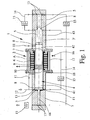
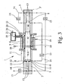
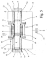
- the Fig. 1 . 3 and 5 show three different embodiments of a fluid working machine 1 according to the invention, wherein the figures are only simplified representations, so that only the essential components for the present invention are shown.
- the fluid working machines 1 shown in the figures serve to compress gases, in particular hydrogen, to a high pressure of, for example, 500 bar. Such fluid working machines 1 can therefore be used advantageously in particular for equipping hydrogen refueling stations.
- the in the Fig. 1 . 3 and 5 1 each have a linear motor 2 for driving a solid-state piston 4 movably arranged in a cylinder 3.
- a linear motor 2 for driving a solid-state piston 4 movably arranged in a cylinder 3.
- a translatory drive force is exerted on the solid-state piston 4, so that the solid-state piston 4 can move axially back and forth within the cylinder 3, 3 '.
- Within the cylinder 3 is at least one compression space 5, for the gas to be compressed, wherein the size of the compression space 5 changes depending on the position of the solid-state piston 4.
- the fluid working machine 1 is formed in a total of 4 stages, so that the compression of the gas takes place in four successive stages. Accordingly, in these two embodiments, four sections 41, 42, 43, 44, each having different diameters, are formed on the solid-body piston 4. Corresponding thereto, the cylinder 3, 3 'has four different sections with different inner diameters, so that a total of four compression chambers 5 are formed.
- the fluid working machine 1 according to Fig. 5 trained only one stage, but this is a double-acting fluid working machine 1, so that on Both sides of the solid-state piston 4 each have a compression space 5 is formed.
- linear motor 2 has a stator with a coil 9 and a rotor with a plurality of magnets 10, wherein the magnets 10 are arranged directly on the solid-state piston 4.
- the can 6 in the radial direction between the rotor, that is, the magnet 10 and the coil 9 of the stator arranged so that the can 6 not only the solid-state piston 4 but also the magnets 10 of the rotor encloses.
- the can 6 is thus between the stator and the rotor, so that the can 6 is penetrated by the magnetic field.
- the compression chamber 5 connected to the can 6 may also be connected directly to the fluid inlet side 12, d. H. the fluid inlet takes place in the compression space 5 connected to the can 6. If the fluid to be compressed has a low temperature, cooling of the linear motor 2 can take place at the same time.
- valves 13 which are arranged in the region of the individual compression chambers 5 and preferably formed as a plate valves.
- the fluid working machines 1 also four intake and exhaust valves 13, respectively.
- Fig. 1 and 3 is also indicated that the individual compression chambers 5 are connected to each other via lines 14, wherein in the individual lines 14 each have a heat exchanger 15 is provided for recooling the compressed gas.
- a coolant circuit 16 for cooling the coil 9 of the stator and thus for cooling the linear motor 2 has a total. The cooling takes place from the outside, that is, via a housing 9 surrounding the coil 9, so that the coil 9 does not come into direct contact with the coolant. Both for re-cooling of the compressed gas in the heat exchangers 15 and for cooling the linear motor 2 while the same coolant can be used.
- the illustrated embodiments of the fluid power machine 1 each have two cylinders 3; 3 ', wherein the linear motor 2 with the split tube 6 or the housing surrounding the linear motor 17 between the two cylinders 3, 3' is arranged.
- the sealing between the end faces of the two cylinders 3, 3 'and the corresponding end faces of the housing 17 takes place via static seals 18th
- the fluid working machines 1 shown in the figures are particularly suitable for compressing gases, preferably hydrogen, to high pressures of, for example, 1000 bar, so that such fluid working machines 1 are particularly suitable for equipping hydrogen refueling stations.
Landscapes
- Engineering & Computer Science (AREA)
- Mechanical Engineering (AREA)
- General Engineering & Computer Science (AREA)
- Physics & Mathematics (AREA)
- Fluid Mechanics (AREA)
- Compressors, Vaccum Pumps And Other Relevant Systems (AREA)
- Linear Motors (AREA)
- Reciprocating Pumps (AREA)
- Electromagnetic Pumps, Or The Like (AREA)
Claims (9)
- Machine à fonctionnement fluidique pour la compression ou le transport de fluides, en particulier pour la compression de gaz à des pressions élevées, avec un moteur linéaire (2), au moins un cylindre (3), un piston plein (4) mobile axialement dans le cylindre (3), au moins une chambre de compression (5) formée entre le cylindre (3) et le piston plein (4) et des soupapes (13) pour l'entrée et la sortie du fluide, qui sont disposées dans la région de ladite au moins une chambre de compression (5), dans laquelle le moteur linéaire (2) transmet une force d'entraînement de translation au piston plein (4), et dans laquelle le piston plein (4) est entouré dans la région du moteur linéaire (2) par un tube fendu (6) disposé de façon fixe, de telle manière qu'une chambre intérieure de cylindre (7) soit formée entre le piston plein (4) et le tube fendu (6),
caractérisée en ce que
la chambre de compression reliée au tube fendu (6) est reliée par une conduite (11) ou un canal au côté d'entrée de fluide (12), de telle manière que la pression dans la chambre intérieure de cylindre (7) entourée par le tube fendu (6) soit réduite. - Machine à fonctionnement fluidique selon la revendication 1, dans laquelle le moteur linéaire (2) présente un stator et un rotor, caractérisée en ce que le tube fendu (6) est disposé en direction radiale entre le rotor et la bobine (9) du stator, de telle manière que le tube fendu (6) entoure le rotor.
- Machine à fonctionnement fluidique selon la revendication 1, dans laquelle le moteur linéaire (2) présente un stator et un rotor, caractérisée en ce qu'aussi bien le rotor que la bobine (9) du stator sont disposés à l'intérieur du tube fendu (6), de telle manière que le tube fendu (6) entoure le rotor et le stator.
- Machine à fonctionnement fluidique selon la revendication 2 ou 3, dans laquelle le rotor présente des aimants (10), caractérisée en ce que les aimants (10) du rotor sont disposés directement sur le piston (4).
- Machine à fonctionnement fluidique selon l'une quelconque des revendications 1 à 4, caractérisée en ce que la compression d'un gaz est effectuée en plusieurs étapes.
- Machine à fonctionnement fluidique selon la revendication 5, caractérisée en ce que le piston plein (4) présente plusieurs sections (41, 42, 43, 44) avec des diamètres di fférents.
- Machine à fonctionnement fluidique selon l'une quelconque des revendications 1 à 6, caractérisée en ce qu'un circuit d'agent de refroidissement (16) est réalisé pour le refroidissement du moteur linéaire (2), en particulier pour le refroidissement de la bobine (9) du stator.
- Machine à fonctionnement fluidique selon l'une quelconque des revendications 1 à 7, caractérisée en ce qu'il est prévu au moins un échangeur de chaleur (15) pour le refroidissement en retour du fluide.
- Machine à fonctionnement fluidique selon une revendication 7 et 8, caractérisé en ce que l'on utilise le même agent de refroidissement ou le fluide à comprimer pour le refroidissement du moteur linéaire (2) et pour le refroidissement en retour du fluide.
Applications Claiming Priority (2)
| Application Number | Priority Date | Filing Date | Title |
|---|---|---|---|
| DE102006060147A DE102006060147B4 (de) | 2006-12-18 | 2006-12-18 | Fluidarbeitsmaschine |
| PCT/EP2007/010872 WO2008074428A1 (fr) | 2006-12-18 | 2007-12-12 | Machine à fonctionnement fluidique |
Publications (2)
| Publication Number | Publication Date |
|---|---|
| EP2122169A1 EP2122169A1 (fr) | 2009-11-25 |
| EP2122169B1 true EP2122169B1 (fr) | 2015-09-23 |
Family
ID=39124605
Family Applications (1)
| Application Number | Title | Priority Date | Filing Date |
|---|---|---|---|
| EP07856620.5A Active EP2122169B1 (fr) | 2006-12-18 | 2007-12-12 | Machine à fonctionnement fluidique |
Country Status (5)
| Country | Link |
|---|---|
| US (1) | US20110052430A1 (fr) |
| EP (1) | EP2122169B1 (fr) |
| JP (2) | JP5431953B2 (fr) |
| DE (1) | DE102006060147B4 (fr) |
| WO (1) | WO2008074428A1 (fr) |
Families Citing this family (28)
| Publication number | Priority date | Publication date | Assignee | Title |
|---|---|---|---|---|
| DE102008036528A1 (de) * | 2008-08-06 | 2010-02-11 | Bentec Gmbh Drilling & Oilfield Systems | Verfahren zum Betrieb einer mehrpulsigen Kolbenpumpe, mehrpulsige Kolbenpumpe sowie Herstellung einer solchen |
| DE102008060659A1 (de) * | 2008-12-08 | 2010-06-10 | Bentec Gmbh Drilling & Oilfield Systems | Klemmvorrichtung für Zylinderbuchsen sowie deren Verwendung und Spülpumpe mit Klemmvorrichtung |
| JP5377162B2 (ja) * | 2009-08-28 | 2013-12-25 | 有限会社いどや | 電磁ポンプ及び此れを用いた電磁ポンプシステム |
| US20110192573A1 (en) | 2010-02-08 | 2011-08-11 | Harmel Defretin | System and method for moving a first fluid using a second fluid |
| DE102010053091A1 (de) * | 2010-12-01 | 2012-06-06 | Linde Aktiengesellschaft | Mehrstufiger Kolbenverdichter |
| DE102012008811A1 (de) | 2012-04-25 | 2013-10-31 | Bpg Beteiligungs Gmbh | Wärmekraftmaschine |
| DE102012016222A1 (de) | 2012-08-01 | 2014-02-06 | Technische Universität Dresden | Kontinuierlich arbeitende Fluidarbeitsmaschine |
| CN103670996B (zh) * | 2012-09-14 | 2016-02-10 | 胜瑞兰工业设备(苏州)有限公司 | 一种无泄漏式磁力驱动往复泵 |
| EP2725227B1 (fr) * | 2012-10-24 | 2015-05-20 | Delphi International Operations Luxembourg S.à r.l. | Ensemble de pompe |
| JP6087713B2 (ja) * | 2013-04-24 | 2017-03-01 | 株式会社神戸製鋼所 | 圧縮装置 |
| US11466678B2 (en) * | 2013-11-07 | 2022-10-11 | Gas Technology Institute | Free piston linear motor compressor and associated systems of operation |
| US10323628B2 (en) * | 2013-11-07 | 2019-06-18 | Gas Technology Institute | Free piston linear motor compressor and associated systems of operation |
| DE102013019499A1 (de) | 2013-11-21 | 2015-05-21 | Linde Aktiengesellschaft | Kolbenverdichter und Verfahren zum Verdichten eines tiefkalten, gasförmigen Mediums, insbesondere Wasserstoff |
| JP6035590B2 (ja) | 2014-05-27 | 2016-11-30 | 株式会社国際電気通信基礎技術研究所 | アクチュエータ装置、ヒューマノイド型ロボットおよびパワーアシスト装置 |
| JP6163646B2 (ja) * | 2014-05-27 | 2017-07-19 | 株式会社国際電気通信基礎技術研究所 | アクチュエータ装置、ヒューマノイド型ロボットおよびパワーアシスト装置 |
| JP6276120B2 (ja) * | 2014-06-27 | 2018-02-07 | 株式会社神戸製鋼所 | ガス圧縮装置 |
| DE102014012977A1 (de) * | 2014-09-08 | 2016-03-10 | Albonair Gmbh | Reduktionsmitteldosiersystem mit verbesserter Förderpumpe |
| JP6276154B2 (ja) * | 2014-09-26 | 2018-02-07 | 株式会社神戸製鋼所 | 往復動型圧縮装置 |
| JP2016213314A (ja) * | 2015-05-08 | 2016-12-15 | 富士通株式会社 | 冷却モジュール及び電子機器 |
| DE102015209728A1 (de) | 2015-05-27 | 2016-12-01 | Robert Bosch Gmbh | Pumpeneinrichtung, Bremssystem |
| CN105443977B (zh) * | 2015-12-28 | 2017-12-26 | 重庆耐德能源装备集成有限公司 | 天然气内冷式液力增压容器 |
| US11118578B2 (en) * | 2017-02-15 | 2021-09-14 | Extiel Holdings, Llc | Internally cooled inline drive compressor |
| CN107605691B (zh) * | 2017-09-08 | 2019-04-02 | 中国神华能源股份有限公司 | 直线驱动柱塞泵、直线驱动乳化液泵系统、及控制方法 |
| WO2019079312A1 (fr) * | 2017-10-17 | 2019-04-25 | Gas Technology Institute | Compresseur à moteur linéaire à piston libre et systèmes de fonctionnement associés |
| PL240516B1 (pl) * | 2018-01-09 | 2022-04-19 | Dobrianski Jurij | Maszyna parowa |
| BE1026881B1 (nl) * | 2018-12-18 | 2020-07-22 | Atlas Copco Airpower Nv | Zuigercompressor |
| BE1026883B1 (nl) * | 2018-12-18 | 2020-07-22 | Atlas Copco Airpower Nv | Zuigercompressor en werkwijze waarin zulke zuigercompressor wordt toegepast |
| JP7330088B2 (ja) * | 2019-12-16 | 2023-08-21 | 株式会社東芝 | 液体ピストン装置および液体ピストン動作方法 |
Family Cites Families (19)
| Publication number | Priority date | Publication date | Assignee | Title |
|---|---|---|---|---|
| US3196797A (en) * | 1961-09-18 | 1965-07-27 | Mario Pagano S P A | Dynamic thrust electromagnetic compressor, particularly suitable for compressing liquid or gaseous substances |
| DE2937157C2 (de) * | 1979-09-13 | 1982-06-16 | Franz Klaus Union Armaturen, Pumpen Gmbh & Co, 4630 Bochum | Kolbenverdrängerpumpe, insbesondere Dosierpumpe |
| US4496287A (en) * | 1980-02-14 | 1985-01-29 | Robert M. Nelson | Sensors for detection of fluid condition, and control systems utilizing their signals |
| NL8204005A (nl) * | 1982-10-18 | 1984-05-16 | Philips Nv | Koelsysteem met twee-traps compressie-inrichting. |
| JPS60125371U (ja) * | 1984-02-03 | 1985-08-23 | 三菱重工業株式会社 | 容積形ポンプまたはブロワ− |
| US4815949A (en) * | 1985-06-24 | 1989-03-28 | Rabson Thomas A | In-well submersible motor with stacked component stator |
| US5354185A (en) * | 1992-10-05 | 1994-10-11 | Aura Systems, Inc. | Electromagnetically actuated reciprocating compressor driver |
| CN1101615C (zh) * | 1997-10-04 | 2003-02-12 | 泽地公司 | 线性电机压缩机 |
| DE19846711C2 (de) * | 1998-10-09 | 2003-05-08 | Trumpf Sachsen Gmbh | Hochdruckpumpe mit Linearmotorantrieb |
| US6183206B1 (en) * | 1999-05-10 | 2001-02-06 | The United States Of America As Represented By The Secretary Of The Air Force | Magnetohydrodynamically-driven compressor |
| DE10149506A1 (de) * | 2001-10-06 | 2003-04-10 | Leybold Vakuum Gmbh | Schwingkolbenantrieb für eine Vakuumpumpe sowie Betriebsverfahren für diesen Antrieb |
| DE10214047A1 (de) * | 2002-03-28 | 2003-10-09 | Volkswagen Ag | Kompressor für eine Fahrzeugklimaanlage |
| DE10314007A1 (de) * | 2003-03-28 | 2004-10-07 | Leybold Vakuum Gmbh | Steuerung einer Kolbenvakuumpumpe |
| JP2005307796A (ja) * | 2004-04-20 | 2005-11-04 | Matsushita Electric Ind Co Ltd | リニア圧縮機 |
| JP2005351255A (ja) * | 2004-06-10 | 2005-12-22 | Kaken Geneqs:Kk | レシプロ圧縮機 |
| DE102004046316A1 (de) * | 2004-09-24 | 2006-03-30 | Linde Ag | Verfahren und Vorrichtung zum Verdichten eines gasförmigen Mediums |
| KR100613514B1 (ko) * | 2004-10-07 | 2006-08-17 | 엘지전자 주식회사 | 리니어 압축기의 토출부 구조 |
| DE102004055924B4 (de) * | 2004-11-19 | 2011-08-18 | Lg Electronics Inc., Seoul | Linearkompressor |
| EP1785625A3 (fr) * | 2005-11-10 | 2009-11-25 | LG Electronics Inc. | Compresseur linéaire |
-
2006
- 2006-12-18 DE DE102006060147A patent/DE102006060147B4/de not_active Expired - Fee Related
-
2007
- 2007-12-12 EP EP07856620.5A patent/EP2122169B1/fr active Active
- 2007-12-12 US US12/519,919 patent/US20110052430A1/en not_active Abandoned
- 2007-12-12 WO PCT/EP2007/010872 patent/WO2008074428A1/fr active Application Filing
- 2007-12-12 JP JP2009541843A patent/JP5431953B2/ja active Active
-
2013
- 2013-12-05 JP JP2013252239A patent/JP5868382B2/ja active Active
Also Published As
| Publication number | Publication date |
|---|---|
| US20110052430A1 (en) | 2011-03-03 |
| DE102006060147B4 (de) | 2009-05-14 |
| DE102006060147A1 (de) | 2008-06-19 |
| JP2014090663A (ja) | 2014-05-15 |
| JP5431953B2 (ja) | 2014-03-05 |
| JP5868382B2 (ja) | 2016-02-24 |
| JP2010513779A (ja) | 2010-04-30 |
| EP2122169A1 (fr) | 2009-11-25 |
| WO2008074428A1 (fr) | 2008-06-26 |
Similar Documents
| Publication | Publication Date | Title |
|---|---|---|
| EP2122169B1 (fr) | Machine à fonctionnement fluidique | |
| EP1999375B1 (fr) | Unité de compression | |
| EP1069313B1 (fr) | Turbo-compresseur | |
| DE112010003623B4 (de) | Lagerungssystem für freikolben-stirling maschinen | |
| EP1574714B1 (fr) | Unité de pompage | |
| EP1963674B1 (fr) | Compresseur a piston refroidi par eau | |
| EP0149219A2 (fr) | Pompe à piston | |
| DE102012202460A1 (de) | Elektromotorische Getriebevorrichtung mit einstückigem Gehäuse | |
| EP3480929B1 (fr) | Carter refroidi pour le stator d'entraînement direct | |
| WO2007110275A1 (fr) | Unité de compresseur | |
| EP3523537B1 (fr) | Compresseur frigorifique semi-hermétique | |
| EP1979622A1 (fr) | Unite de compresseur | |
| DE102010064061A1 (de) | Turboverdichter und Verfahren zur Verdichtung von Gas | |
| DE102011077096A1 (de) | Pendelschieberpumpe | |
| WO2013017669A1 (fr) | Dispositif de compression ainsi qu'un dispositif de réfrigération qui en est équipé et une machine frigorifique qui en est équipée | |
| WO2008019815A1 (fr) | Refroidissement de rotor pour pompes à vide ou compresseurs à deux arbres fonctionnant à sec | |
| EP2795204B1 (fr) | Compresseur | |
| DE102010015932B4 (de) | Solenoidventil für die Durchstromsteuerung | |
| DE102018206401A1 (de) | Elektromotor und Verfahren zur Herstellung desselben | |
| DE102018203264A1 (de) | Hydraulischer Aktor | |
| DE102018124757B4 (de) | Elektrisch angetriebene Verdichteranordnung | |
| DE102021102648B4 (de) | Kolbenkompressor, insbesondere für eine Wärmepumpe | |
| DE102011080377A1 (de) | Kompressorvorrichtung sowie eine damit ausgerüstete Kühlvorrichtung und eine damit ausgerüstete Kältemaschine | |
| WO2016193262A1 (fr) | Pompe filtrante hydraulique électrique et pompe volumétrique hydraulique électrique à utiliser dans une pompe filtrante hydraulique | |
| DE102021207660A1 (de) | Linearverdichter |
Legal Events
| Date | Code | Title | Description |
|---|---|---|---|
| PUAI | Public reference made under article 153(3) epc to a published international application that has entered the european phase |
Free format text: ORIGINAL CODE: 0009012 |
|
| 17P | Request for examination filed |
Effective date: 20090715 |
|
| AK | Designated contracting states |
Kind code of ref document: A1 Designated state(s): AT BE BG CH CY CZ DE DK EE ES FI FR GB GR HU IE IS IT LI LT LU LV MC MT NL PL PT RO SE SI SK TR |
|
| DAX | Request for extension of the european patent (deleted) | ||
| 17Q | First examination report despatched |
Effective date: 20100301 |
|
| GRAP | Despatch of communication of intention to grant a patent |
Free format text: ORIGINAL CODE: EPIDOSNIGR1 |
|
| INTG | Intention to grant announced |
Effective date: 20150330 |
|
| GRAS | Grant fee paid |
Free format text: ORIGINAL CODE: EPIDOSNIGR3 |
|
| GRAA | (expected) grant |
Free format text: ORIGINAL CODE: 0009210 |
|
| AK | Designated contracting states |
Kind code of ref document: B1 Designated state(s): AT BE BG CH CY CZ DE DK EE ES FI FR GB GR HU IE IS IT LI LT LU LV MC MT NL PL PT RO SE SI SK TR |
|
| REG | Reference to a national code |
Ref country code: GB Ref legal event code: FG4D Free format text: NOT ENGLISH |
|
| REG | Reference to a national code |
Ref country code: CH Ref legal event code: EP |
|
| REG | Reference to a national code |
Ref country code: AT Ref legal event code: REF Ref document number: 751404 Country of ref document: AT Kind code of ref document: T Effective date: 20151015 |
|
| REG | Reference to a national code |
Ref country code: IE Ref legal event code: FG4D Free format text: LANGUAGE OF EP DOCUMENT: GERMAN |
|
| REG | Reference to a national code |
Ref country code: DE Ref legal event code: R096 Ref document number: 502007014253 Country of ref document: DE |
|
| REG | Reference to a national code |
Ref country code: FR Ref legal event code: PLFP Year of fee payment: 9 |
|
| PG25 | Lapsed in a contracting state [announced via postgrant information from national office to epo] |
Ref country code: LT Free format text: LAPSE BECAUSE OF FAILURE TO SUBMIT A TRANSLATION OF THE DESCRIPTION OR TO PAY THE FEE WITHIN THE PRESCRIBED TIME-LIMIT Effective date: 20150923 Ref country code: GR Free format text: LAPSE BECAUSE OF FAILURE TO SUBMIT A TRANSLATION OF THE DESCRIPTION OR TO PAY THE FEE WITHIN THE PRESCRIBED TIME-LIMIT Effective date: 20151224 Ref country code: LV Free format text: LAPSE BECAUSE OF FAILURE TO SUBMIT A TRANSLATION OF THE DESCRIPTION OR TO PAY THE FEE WITHIN THE PRESCRIBED TIME-LIMIT Effective date: 20150923 Ref country code: FI Free format text: LAPSE BECAUSE OF FAILURE TO SUBMIT A TRANSLATION OF THE DESCRIPTION OR TO PAY THE FEE WITHIN THE PRESCRIBED TIME-LIMIT Effective date: 20150923 |
|
| REG | Reference to a national code |
Ref country code: LT Ref legal event code: MG4D |
|
| REG | Reference to a national code |
Ref country code: NL Ref legal event code: FP |
|
| PG25 | Lapsed in a contracting state [announced via postgrant information from national office to epo] |
Ref country code: SE Free format text: LAPSE BECAUSE OF FAILURE TO SUBMIT A TRANSLATION OF THE DESCRIPTION OR TO PAY THE FEE WITHIN THE PRESCRIBED TIME-LIMIT Effective date: 20150923 |
|
| PG25 | Lapsed in a contracting state [announced via postgrant information from national office to epo] |
Ref country code: SK Free format text: LAPSE BECAUSE OF FAILURE TO SUBMIT A TRANSLATION OF THE DESCRIPTION OR TO PAY THE FEE WITHIN THE PRESCRIBED TIME-LIMIT Effective date: 20150923 Ref country code: CZ Free format text: LAPSE BECAUSE OF FAILURE TO SUBMIT A TRANSLATION OF THE DESCRIPTION OR TO PAY THE FEE WITHIN THE PRESCRIBED TIME-LIMIT Effective date: 20150923 Ref country code: IS Free format text: LAPSE BECAUSE OF FAILURE TO SUBMIT A TRANSLATION OF THE DESCRIPTION OR TO PAY THE FEE WITHIN THE PRESCRIBED TIME-LIMIT Effective date: 20160123 Ref country code: EE Free format text: LAPSE BECAUSE OF FAILURE TO SUBMIT A TRANSLATION OF THE DESCRIPTION OR TO PAY THE FEE WITHIN THE PRESCRIBED TIME-LIMIT Effective date: 20150923 Ref country code: ES Free format text: LAPSE BECAUSE OF FAILURE TO SUBMIT A TRANSLATION OF THE DESCRIPTION OR TO PAY THE FEE WITHIN THE PRESCRIBED TIME-LIMIT Effective date: 20150923 |
|
| PG25 | Lapsed in a contracting state [announced via postgrant information from national office to epo] |
Ref country code: RO Free format text: LAPSE BECAUSE OF FAILURE TO SUBMIT A TRANSLATION OF THE DESCRIPTION OR TO PAY THE FEE WITHIN THE PRESCRIBED TIME-LIMIT Effective date: 20150923 Ref country code: PL Free format text: LAPSE BECAUSE OF FAILURE TO SUBMIT A TRANSLATION OF THE DESCRIPTION OR TO PAY THE FEE WITHIN THE PRESCRIBED TIME-LIMIT Effective date: 20150923 Ref country code: BE Free format text: LAPSE BECAUSE OF NON-PAYMENT OF DUE FEES Effective date: 20151231 Ref country code: PT Free format text: LAPSE BECAUSE OF FAILURE TO SUBMIT A TRANSLATION OF THE DESCRIPTION OR TO PAY THE FEE WITHIN THE PRESCRIBED TIME-LIMIT Effective date: 20160125 |
|
| REG | Reference to a national code |
Ref country code: DE Ref legal event code: R097 Ref document number: 502007014253 Country of ref document: DE |
|
| PG25 | Lapsed in a contracting state [announced via postgrant information from national office to epo] |
Ref country code: LU Free format text: LAPSE BECAUSE OF FAILURE TO SUBMIT A TRANSLATION OF THE DESCRIPTION OR TO PAY THE FEE WITHIN THE PRESCRIBED TIME-LIMIT Effective date: 20151212 Ref country code: MC Free format text: LAPSE BECAUSE OF FAILURE TO SUBMIT A TRANSLATION OF THE DESCRIPTION OR TO PAY THE FEE WITHIN THE PRESCRIBED TIME-LIMIT Effective date: 20150923 |
|
| PLBE | No opposition filed within time limit |
Free format text: ORIGINAL CODE: 0009261 |
|
| STAA | Information on the status of an ep patent application or granted ep patent |
Free format text: STATUS: NO OPPOSITION FILED WITHIN TIME LIMIT |
|
| GBPC | Gb: european patent ceased through non-payment of renewal fee |
Effective date: 20151223 |
|
| 26N | No opposition filed |
Effective date: 20160624 |
|
| PG25 | Lapsed in a contracting state [announced via postgrant information from national office to epo] |
Ref country code: DK Free format text: LAPSE BECAUSE OF FAILURE TO SUBMIT A TRANSLATION OF THE DESCRIPTION OR TO PAY THE FEE WITHIN THE PRESCRIBED TIME-LIMIT Effective date: 20150923 |
|
| REG | Reference to a national code |
Ref country code: IE Ref legal event code: MM4A |
|
| PG25 | Lapsed in a contracting state [announced via postgrant information from national office to epo] |
Ref country code: GB Free format text: LAPSE BECAUSE OF NON-PAYMENT OF DUE FEES Effective date: 20151223 Ref country code: IE Free format text: LAPSE BECAUSE OF NON-PAYMENT OF DUE FEES Effective date: 20151212 |
|
| PG25 | Lapsed in a contracting state [announced via postgrant information from national office to epo] |
Ref country code: SI Free format text: LAPSE BECAUSE OF FAILURE TO SUBMIT A TRANSLATION OF THE DESCRIPTION OR TO PAY THE FEE WITHIN THE PRESCRIBED TIME-LIMIT Effective date: 20150923 |
|
| REG | Reference to a national code |
Ref country code: FR Ref legal event code: PLFP Year of fee payment: 10 |
|
| PG25 | Lapsed in a contracting state [announced via postgrant information from national office to epo] |
Ref country code: HU Free format text: LAPSE BECAUSE OF FAILURE TO SUBMIT A TRANSLATION OF THE DESCRIPTION OR TO PAY THE FEE WITHIN THE PRESCRIBED TIME-LIMIT; INVALID AB INITIO Effective date: 20071212 Ref country code: BG Free format text: LAPSE BECAUSE OF FAILURE TO SUBMIT A TRANSLATION OF THE DESCRIPTION OR TO PAY THE FEE WITHIN THE PRESCRIBED TIME-LIMIT Effective date: 20150923 |
|
| PG25 | Lapsed in a contracting state [announced via postgrant information from national office to epo] |
Ref country code: CY Free format text: LAPSE BECAUSE OF FAILURE TO SUBMIT A TRANSLATION OF THE DESCRIPTION OR TO PAY THE FEE WITHIN THE PRESCRIBED TIME-LIMIT Effective date: 20150923 |
|
| PG25 | Lapsed in a contracting state [announced via postgrant information from national office to epo] |
Ref country code: MT Free format text: LAPSE BECAUSE OF FAILURE TO SUBMIT A TRANSLATION OF THE DESCRIPTION OR TO PAY THE FEE WITHIN THE PRESCRIBED TIME-LIMIT Effective date: 20150923 Ref country code: TR Free format text: LAPSE BECAUSE OF FAILURE TO SUBMIT A TRANSLATION OF THE DESCRIPTION OR TO PAY THE FEE WITHIN THE PRESCRIBED TIME-LIMIT Effective date: 20150923 |
|
| REG | Reference to a national code |
Ref country code: FR Ref legal event code: PLFP Year of fee payment: 11 |
|
| PGFP | Annual fee paid to national office [announced via postgrant information from national office to epo] |
Ref country code: NL Payment date: 20231220 Year of fee payment: 17 Ref country code: IT Payment date: 20231228 Year of fee payment: 17 Ref country code: FR Payment date: 20231221 Year of fee payment: 17 Ref country code: AT Payment date: 20231221 Year of fee payment: 17 |
|
| PGFP | Annual fee paid to national office [announced via postgrant information from national office to epo] |
Ref country code: DE Payment date: 20240222 Year of fee payment: 17 Ref country code: CH Payment date: 20240101 Year of fee payment: 17 |