EP2116165B1 - Bas d'aspiration pour aspirateurs - Google Patents
Bas d'aspiration pour aspirateurs Download PDFInfo
- Publication number
- EP2116165B1 EP2116165B1 EP20090005978 EP09005978A EP2116165B1 EP 2116165 B1 EP2116165 B1 EP 2116165B1 EP 20090005978 EP20090005978 EP 20090005978 EP 09005978 A EP09005978 A EP 09005978A EP 2116165 B1 EP2116165 B1 EP 2116165B1
- Authority
- EP
- European Patent Office
- Prior art keywords
- suction
- suction nozzle
- nozzle according
- suction port
- chamber
- Prior art date
- Legal status (The legal status is an assumption and is not a legal conclusion. Google has not performed a legal analysis and makes no representation as to the accuracy of the status listed.)
- Active
Links
- 238000007789 sealing Methods 0.000 claims description 13
- 239000000463 material Substances 0.000 claims description 7
- 239000004753 textile Substances 0.000 claims description 7
- 229920002457 flexible plastic Polymers 0.000 claims description 3
- 239000002131 composite material Substances 0.000 claims description 2
- 239000004744 fabric Substances 0.000 claims description 2
- 239000002245 particle Substances 0.000 description 14
- 239000000428 dust Substances 0.000 description 5
- 239000002689 soil Substances 0.000 description 4
- 238000010521 absorption reaction Methods 0.000 description 2
- 238000004140 cleaning Methods 0.000 description 2
- 239000011362 coarse particle Substances 0.000 description 2
- 238000011109 contamination Methods 0.000 description 2
- 230000000694 effects Effects 0.000 description 2
- 238000009408 flooring Methods 0.000 description 2
- 230000003068 static effect Effects 0.000 description 2
- 230000015572 biosynthetic process Effects 0.000 description 1
- 230000001680 brushing effect Effects 0.000 description 1
- 238000005520 cutting process Methods 0.000 description 1
- 230000006866 deterioration Effects 0.000 description 1
- 238000006073 displacement reaction Methods 0.000 description 1
- 230000008030 elimination Effects 0.000 description 1
- 238000003379 elimination reaction Methods 0.000 description 1
- 238000004519 manufacturing process Methods 0.000 description 1
- 239000013618 particulate matter Substances 0.000 description 1
- 230000035515 penetration Effects 0.000 description 1
- 238000003825 pressing Methods 0.000 description 1
- 238000005096 rolling process Methods 0.000 description 1
Images


Classifications
-
- A—HUMAN NECESSITIES
- A47—FURNITURE; DOMESTIC ARTICLES OR APPLIANCES; COFFEE MILLS; SPICE MILLS; SUCTION CLEANERS IN GENERAL
- A47L—DOMESTIC WASHING OR CLEANING; SUCTION CLEANERS IN GENERAL
- A47L9/00—Details or accessories of suction cleaners, e.g. mechanical means for controlling the suction or for effecting pulsating action; Storing devices specially adapted to suction cleaners or parts thereof; Carrying-vehicles specially adapted for suction cleaners
- A47L9/02—Nozzles
- A47L9/04—Nozzles with driven brushes or agitators
- A47L9/0405—Driving means for the brushes or agitators
- A47L9/0411—Driving means for the brushes or agitators driven by electric motor
-
- A—HUMAN NECESSITIES
- A47—FURNITURE; DOMESTIC ARTICLES OR APPLIANCES; COFFEE MILLS; SPICE MILLS; SUCTION CLEANERS IN GENERAL
- A47L—DOMESTIC WASHING OR CLEANING; SUCTION CLEANERS IN GENERAL
- A47L9/00—Details or accessories of suction cleaners, e.g. mechanical means for controlling the suction or for effecting pulsating action; Storing devices specially adapted to suction cleaners or parts thereof; Carrying-vehicles specially adapted for suction cleaners
- A47L9/02—Nozzles
- A47L9/04—Nozzles with driven brushes or agitators
- A47L9/0405—Driving means for the brushes or agitators
- A47L9/0416—Driving means for the brushes or agitators driven by fluid pressure, e.g. by means of an air turbine
-
- A—HUMAN NECESSITIES
- A47—FURNITURE; DOMESTIC ARTICLES OR APPLIANCES; COFFEE MILLS; SPICE MILLS; SUCTION CLEANERS IN GENERAL
- A47L—DOMESTIC WASHING OR CLEANING; SUCTION CLEANERS IN GENERAL
- A47L9/00—Details or accessories of suction cleaners, e.g. mechanical means for controlling the suction or for effecting pulsating action; Storing devices specially adapted to suction cleaners or parts thereof; Carrying-vehicles specially adapted for suction cleaners
- A47L9/02—Nozzles
- A47L9/04—Nozzles with driven brushes or agitators
- A47L9/0494—Height adjustment of dust-loosening tools
-
- A—HUMAN NECESSITIES
- A47—FURNITURE; DOMESTIC ARTICLES OR APPLIANCES; COFFEE MILLS; SPICE MILLS; SUCTION CLEANERS IN GENERAL
- A47L—DOMESTIC WASHING OR CLEANING; SUCTION CLEANERS IN GENERAL
- A47L9/00—Details or accessories of suction cleaners, e.g. mechanical means for controlling the suction or for effecting pulsating action; Storing devices specially adapted to suction cleaners or parts thereof; Carrying-vehicles specially adapted for suction cleaners
- A47L9/02—Nozzles
- A47L9/06—Nozzles with fixed, e.g. adjustably fixed brushes or the like
- A47L9/0666—Nozzles with fixed, e.g. adjustably fixed brushes or the like with tilting, floating or similarly arranged brushes, combs, lips or pads
Definitions
- the invention relates to a suction nozzle for vacuum cleaner, which is universally applicable to smooth floors and textile floor coverings.
- the basic structure of the suction nozzle includes a housing, which is based on the suction direction front and rear rollers supported, and extending over the entire width of the housing suction chamber with a bottom open suction mouth, its orientation to the bottom surface by a pivoting movement to one to the suction transversely and the bottom surface parallel pivot axis is variable.
- a suction channel is arranged, which opens at its suction direction relative to the front end into the suction chamber and has at its rear end a pivotable Saugrohran gleich Swiss.
- the suction nozzle can be a static nozzle without rotating internals or a brush attachment with a brush roller driven by an air turbine or an electric motor.
- rollers it is also possible to use other support elements known to the person skilled in the art, e.g. Slider, be provided.
- a static suction nozzle with the features described above is known from DE 42 43 244 C2 known, which describes the features of the preamble of independent claim 1.
- a brush attachment, which has a pivotally mounted suction chamber is in the DE 199 38 325 A1 described.
- the known embodiments of the suction nozzles have the common disadvantage that soils, which are polluted even with coarse dirt particles of different grain size up to the dimension of a pea, can not or only very poorly cleaned with these nozzles. The reason for this is essentially that during the reciprocation of the suction nozzle when sucking the dirt particles do not get under the nozzle, but are moved in front of the nozzle on the floor. The displacement of the dirt particles is on the one hand to their elimination and on the other can damage sensitive floor coverings by scratches.
- Tilting the nozzle relative to the bottom surface to increase the ground clearance at one of the sides of the nozzle provides no remedy, for example, as the rotating brush of a brush attachment would lose ground contact by tilting the device.
- the brush roller would not only lose their cleaning effect, but it would increase the speed of the brush roller due to the lack of ground contact immediately significantly, which would have a disturbing and not acceptable in practice noise development.
- the invention is therefore an object of the invention to provide a suction nozzle for vacuum cleaner, whose properties are significantly improved with respect to their Grobschmutz- and dust removal both with and without rotating brushes over conventional nozzles with the smallest possible design effort.
- a suction nozzle the suction mouth is reversibly fixed in a functional position for absorbing coarse dirt by means of an accessible on the outside of the housing actuator and whose suction mouth is inclined in this designated as coarse dirt position functional position to the bottom surface such that a front suction mouth has sufficient for sucking coarse dirt distance to the bottom surface, said distance is in particular more than 3 mm and preferably 5 mm to 10 mm.
- the suction mouth of the suction nozzle is firmly connected to the suction chamber.
- the suction chamber is rotatably mounted about the pivot axis.
- the suction nozzle is preferably designed so that its housing has a substantially rectangular plan, so that the suction chamber extends approximately over the entire longitudinal side of the housing.
- a suction nozzle is pivotally mounted, which forms the suction mouth.
- the fixation of the suction mouth in the coarse dirt position is effected by a non-positive or positive locking of the pivotable element, which can be designed in particular as a releasable latching connection.
- the embodiments described make it possible to fix the suction mouth in one or more positions.
- the rocker arm of the pivotable element with an accessible, for example, at the top of the housing actuator is adjustable and can be adapted to the degree of contamination of the soil with coarse particles.
- the actuator also elsewhere, z. B. on the front, the back or even on the underside of the suction head can be arranged.
- the actuating device has a foot switch, so that the user of the suction nozzle can easily change during the suction in the coarse dirt position.
- sealing elements are arranged in the suction nozzle according to the invention on its underside along the housing edges, which seal the suction space between the suction nozzle and the bottom surface. Due to the bottom-side sealing of the suction chamber, a sufficient negative pressure is set on the underside of the housing, which is necessary for receiving both fine and coarse dust particles.
- the sealing elements are designed in particular as bristle strips or as flexible plastic lips.
- the sealing element in the region of the front longitudinal side of a softer, more flexible material than the material from which the sealing element is formed in the region of the rear longitudinal side.
- the coarse dirt particles are run over and reach the suction chamber below the suction nozzle.
- the stiffer-shaped sealing element on the rear longitudinal side collects dirt particles that have already reached the area below the suction nozzle, but have not yet been detected by the suction air flow.
- the suction chamber in a section perpendicular to its pivot axis at least over part of its circumference on a cylindrical cross-sectional profile which is flattened expediently between the Saugmundkanten.
- the invention teaches that the pivotable suction chamber or the suction mouth pivotable on the suction chamber in the region of the rear suction mouth has a support element which rests in the coarse dirt position on the bottom surface to be sucked, the suction head in the coarse dirt position on the support member and the back Rolling is supported and thereby adjusts a larger ground clearance on the front side of the suction head.
- the locking of the suction chamber or the suction nozzle in the coarse dirt position also causes a front-side lifting of the housing so that coarse dirt particles can easily get into the suction chamber on the underside of the housing with a forward movement of the suction nozzle.
- the support element ensures a secure guidance of the suction nozzle on the floor covering and prevents tilting of the nozzle and thus the formation of lateral suction air leakage flows, which would have a deterioration of the suction property in particular with respect to fine dust particles result.
- the support member may be formed as a skid, on the bottom side preferably a textile covering, a felt, a plush fabric or a composite material produced using such a material is attached. Thus, the runner of the support element slides smoothly over the floor covering without damaging it.
- the common axis of rotation extends parallel to the pivot axis of the suction chamber.
- a brush roller is rotatably mounted in the suction chamber.
- the axis of rotation of the brush roller and the axis of rotation of the suction chamber may for example be arranged in alignment.
- the brush roller is a turbine wheel driven by the suction air flow or an electric motor arranged in the suction head are assigned as a drive.
- the design of the nozzle with a arranged in the pivotable suction chamber brush roller offers over a nozzle without brush roller insofar an improvement in the suction properties, as is cleaned by the brush roller flooring not only by the Saugluftströmung of dirt, but also by the brushing action of the rotating roller.
- the suction nozzle in a coarse dirt position, the effect of the brush roller is combined with the advantages of the coarse dirt suction properties.
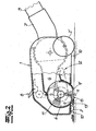
- the suction nozzle For the basic structure of the suction nozzle shown in the figures includes a housing 1, which is based on the suction direction X front and back on rollers 2, 2 'supported.
- the housing 1 may have a in Have substantially rectangular floor plan.
- the suction nozzle can be connected to a suction tube 3 and a suction hose to a vacuum cleaner.
- the suction nozzle comprises a suction chamber 4, which extends transversely to the cutting plane substantially over the entire width of the housing.
- the suction chamber 4 has a bottom open suction port 5, the orientation of the bottom surface by a pivoting movement about a transverse to the suction X and the bottom surface parallel pivot axis S is variable.
- a suction channel 6 is arranged, which opens at its front end in the suction direction X into the suction chamber 4 and at its rear end has a pivotable Saugrohran gleich Swiss 7.
- a running as a foot switch actuator 8 is accessible, with which the position of the suction chamber 4 is reversibly fixed.
- the actuating device 8 is arranged on the upper side of the housing 1.
- the suction mouth 5 is firmly connected to the suction chamber 4.
- the suction chamber 4 is rotatably mounted about the pivot axis S.
- the in the in Fig. 1 shown position of the suction chamber 4 is preferably suitable for cleaning soils that are mainly contaminated with fine dust particles, since both the front and the rear suction mouth 9, 9 'have a small distance from the ground surface.
- the suction chamber 4 together with the suction mouth 5 is preferably pivotable in this functional position, so that the Saugmundkanten 9, 9 'can adjust to uneven floors and always align optimally to the bottom surface when the rollers 2, 2', for example, sink into a deep pile carpet or the suction nozzle is lifted slightly in a backward movement by pulling the suction tube 3 from the bottom surface.
- a rotatably mounted brush roller 11 is arranged, which is driven by a motor 12 or alternatively by a turbine wheel rotating in the suction air flow.
- the suction chamber 4 in a section perpendicular to the pivot axis at least over part of its circumference on a cylindrical cross-sectional profile, wherein the profile between the suction mouth edges 9, 9 'is flattened.
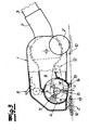
- the Fig. 2 shows the suction nozzle according to the invention in a functional position for absorbing coarse dirt.
- the suction chamber 4 and the suction mouth 5 fixedly connected thereto are reversibly fixed in this functional position by means of the actuating device 8 arranged on the upper side in this embodiment in such a way that the front suction mouth 9 has a distance a sufficient to suck coarse dirt 13.
- the distance a of the front suction mouth 9 to the bottom is at least 3 mm.
- a distance a between 5 mm and 10 mm can be set.
- the fixation is preferably carried out by a releasable latching connection or another suitable frictional or positive connection.
- a suction nozzle is shown, at the back Saugmundkante 9 'of the suction chamber 4 firmly connected suction mouth 5, a support member 14 is arranged, which rests on the bottom surface to be sucked when the pivotable suction chamber 4 is pivoted together with the suction mouth 5 in the coarse dirt position.
- the support member 14 consists of a skid, which may be covered with a textile covering, plush, felt or the like, or support rollers whose common axis of rotation 15 extends parallel to the pivot axis S.
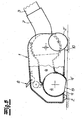
- Fig. 4 shows a suction nozzle, in which in the suction chamber 4, a suction nozzle 16 is pivotally mounted, which forms the suction mouth 5.
- a suction nozzle 16 is pivotally mounted, which forms the suction mouth 5.
- a suction nozzle without rotating internals which has a pivotally mounted suction chamber 4 with firmly connected suction mouth 5.
- the suction chamber 4 and with it the suction mouth 5 are fixed in a functional position for absorbing coarse dirt.
- the pivoting is done by a on the outside of the housing 1 accessible foot switch 8.
- a sealing element 10, which z. B. is formed in the form of a bristle strip or a rubber lip.
Landscapes
- Engineering & Computer Science (AREA)
- Mechanical Engineering (AREA)
- Nozzles For Electric Vacuum Cleaners (AREA)
Claims (16)
- Buse d'aspiration pour aspirateur de sol, avec
un boîtier (1), qui par rapport à la direction d'aspiration est soutenu côté frontal et côté arrière sur des galets (2, 2') et
une chambre d'aspiration (4) s'étendant sensiblement sur toute la largeur du boîtier (1), avec une bouche aspirante (5) ouverte côté sol dont l'orientation par rapport à la surface du sol est variable par un mouvement de pivotement autour d'un axe de pivotement (S) s'étendant à la transversale de la direction d'aspiration et à la parallèle de la surface du sol,
dans le boîtier (1) étant disposé un canal d'aspiration (6) qui sur son extrémité avant par rapport à la direction d'aspiration débouche dans la chambre d'aspiration (4) et sur son extrémité côté arrière comporte une pièce de raccordement sur le tuyau d'aspiration (7), caractérisée en ce que dans une position fonctionnelle pour l'aspiration de saletés grossières, la bouche aspirante (5) peut se fixer de manière réversible à l'aide d'un dispositif de manoeuvre (8) accessible sur la face extérieure du boîtier et en ce que dans ladite position fonctionnelle appelée position pour saletés grossières, la bouche aspirante (5) est inclinée vers la surface du sol de telle sorte que l'arête frontale de la bouche aspirante (9) présente une distance (a) suffisante par rapport au sol pour l'aspiration de saletés grossières. - Buse d'aspiration selon la revendication 1, caractérisée en ce que la distance (a) entre l'arête frontale de bouche aspirante (9) de la bouche aspirante (5) et la surface du sol est supérieure à 3 mm, est comprise de préférence entre 5 mm et 10 mm lorsque la bouche aspirante (5) est fixée dans la position pour saletés grossières.
- Buse d'aspiration selon la revendication 1 ou 2, caractérisée en ce que la bouche aspirante (5) est fixement reliée à la chambre d'aspiration (4) et en ce que la chambre d'aspiration (4) est logée de manière mobile en rotation autour de l'axe de pivotement (S).
- Buse d'aspiration selon la revendication 1 ou 2, caractérisée en ce que sur la chambre d'aspiration (4), une pièce de bouche aspirante qui forme la bouche aspirante (5) est logée de manière mobile en pivotement.
- Buse d'aspiration selon l'une quelconque des revendications 1 à 4, caractérisée en ce que la fixation de la bouche aspirante (5) dans la position pour saletés grossières s'effectue par un blocage par complémentarité de force ou de forme de l'élément mobile en pivotement (4, 5), notamment par une liaison par enclenchement amovible.
- Buse d'aspiration selon l'une quelconque des revendications 1 à 5, caractérisée en ce que le dispositif de manoeuvre (8) comporte un interrupteur à commande au pied.
- Buse d'aspiration selon l'une quelconque des revendications 1 à 6, caractérisée en ce que sur la face inférieure du boîtier (1), le long des arêtes du boîtier sont disposés des éléments d'étanchéité (10) qui assurent l'étanchéité de l'espace d'aspiration entre la buse d'aspiration et la surface du sol.
- Buse d'aspiration selon la revendication 7, caractérisée en ce que les éléments d'étanchéité (10) sont conçus sous la forme de bandes de poils de brosse ou de lèvres flexibles en matière plastique.
- Buse d'aspiration selon la revendication 7 ou 8, caractérisée en ce que dans la zone du côté longitudinal frontal, l'élément d'étanchéité (10) est constitué d'une matière plus souple et plus flexible que la matière dans laquelle est formé l'élément d'étanchéité dans la zone du côté longitudinal arrière.
- Buse d'aspiration selon l'une quelconque des revendications 1 à 9, caractérisée en ce que dans une coupe à la perpendiculaire de l'axe de pivotement (S), la chambre d'aspiration (4) présente au moins sur une partie de sa périphérie un profil de section transversale cylindrique.
- Buse d'aspiration selon la revendication 10, caractérisée en ce que dans la zone de la bouche aspirante (5), la chambre d'aspiration (4) présente un profil aplati entre les arêtes de bouche aspirante (9, 9').
- Buse d'aspiration selon l'une quelconque des revendications 1 à 11, caractérisée en ce que le chambre d'aspiration (4) pivotante ou la pièce de bouche aspirante pivotante sur la chambre d'aspiration comporte dans la zone de l'arête arrière de bouche aspirante (9') un élément d'appui (14) qui dans la position pour saletés grossières repose sur la surface de sol à aspirer, dans la position pour saletés grossières, la tête aspirante s'appuyant sur l'élément d'appui (14) ainsi que sur les galets arrière (2) et en ce qu'il s'installe de ce fait une distance plus importante par rapport au sol (a) sur la face frontale de la tête aspirante.
- Buse d'aspiration selon la revendication 12, caractérisée en ce que l'élément d'appui (14) est conçu en tant que patin coulissant, sur lequel est fixé de préférence côté sol un revêtement textile, un feutre, un tissu pelucheux ou une matière composite fabriquée à partir d'une telle matière.
- Buse d'aspiration selon la revendication 12, caractérisée en ce que sur l'élément d'appui (14), un ou plusieurs galets d'appui, dont l'axe de rotation (15) commun s'étend à la parallèle de l'axe de pivotement (S) de la chambre d'aspiration (4) sont logés de manière rotative.
- Buse d'aspiration selon l'une quelconque des revendications 1 à 14, caractérisée en ce que dans la chambre d'aspiration (4) un rouleau à brosse (11) est logé de manière rotative.
- Buse d'aspiration pour aspirateur de sol selon la revendication 15, caractérisée en ce qu'au rouleau à brosse (11) est associé en tant qu'entraînement (12) une roue de turbine ou un moteur électrique disposé dans tête aspirante.
Applications Claiming Priority (1)
| Application Number | Priority Date | Filing Date | Title |
|---|---|---|---|
| DE200810022995 DE102008022995B4 (de) | 2008-05-09 | 2008-05-09 | Saugdüse für Bodenstaubsauger |
Publications (3)
| Publication Number | Publication Date |
|---|---|
| EP2116165A2 EP2116165A2 (fr) | 2009-11-11 |
| EP2116165A3 EP2116165A3 (fr) | 2011-06-08 |
| EP2116165B1 true EP2116165B1 (fr) | 2012-09-19 |
Family
ID=41061174
Family Applications (1)
| Application Number | Title | Priority Date | Filing Date |
|---|---|---|---|
| EP20090005978 Active EP2116165B1 (fr) | 2008-05-09 | 2009-04-30 | Bas d'aspiration pour aspirateurs |
Country Status (2)
| Country | Link |
|---|---|
| EP (1) | EP2116165B1 (fr) |
| DE (1) | DE102008022995B4 (fr) |
Cited By (2)
| Publication number | Priority date | Publication date | Assignee | Title |
|---|---|---|---|---|
| CN105392406A (zh) * | 2013-05-02 | 2016-03-09 | 伊莱克斯公司 | 用于真空吸尘器的清洁吸嘴 |
| AU2017394582B2 (en) * | 2017-01-19 | 2020-07-02 | Lg Electronics Inc. | Cleaner |
Families Citing this family (5)
| Publication number | Priority date | Publication date | Assignee | Title |
|---|---|---|---|---|
| DE102010002629B4 (de) * | 2010-03-05 | 2013-12-12 | BSH Bosch und Siemens Hausgeräte GmbH | Bürstenkopf für ein Reinigungsgerät und Reinigungsgerät |
| GB2487920B (en) * | 2011-02-08 | 2013-01-09 | Dyson Technology Ltd | A cleaner head |
| DE102011053412A1 (de) * | 2011-09-08 | 2013-03-14 | Wessel-Werk Gmbh | Tischsauger |
| CN102743133B (zh) * | 2012-06-17 | 2014-09-17 | 张光裕 | 地毯清洁机 |
| WO2014122219A1 (fr) * | 2013-02-07 | 2014-08-14 | Aktiebolaget Electrolux | Buse d'aspirateur comportant un moyen de support |
Family Cites Families (4)
| Publication number | Priority date | Publication date | Assignee | Title |
|---|---|---|---|---|
| DE4243244C2 (de) * | 1992-12-19 | 1999-11-04 | Miele & Cie | Mit Laufrädern versehene Bodendüse für Staubsauger |
| DE19505106C2 (de) * | 1995-02-16 | 1997-04-17 | Stein & Co Gmbh | Vorrichtung für Bodenpflegegeräte |
| DE19938325C2 (de) * | 1999-08-12 | 2003-09-18 | Wessel Werk Gmbh | Bürstenvorsatzgerät zum Reinigen von Bodenflächen |
| DE10201961B4 (de) * | 2002-01-19 | 2006-04-27 | Wessel-Werk Gmbh | Staubsaugerdüse ohne rotierende Einbauten für Glattböden und textile Bodenbeläge |
-
2008
- 2008-05-09 DE DE200810022995 patent/DE102008022995B4/de not_active Expired - Fee Related
-
2009
- 2009-04-30 EP EP20090005978 patent/EP2116165B1/fr active Active
Cited By (2)
| Publication number | Priority date | Publication date | Assignee | Title |
|---|---|---|---|---|
| CN105392406A (zh) * | 2013-05-02 | 2016-03-09 | 伊莱克斯公司 | 用于真空吸尘器的清洁吸嘴 |
| AU2017394582B2 (en) * | 2017-01-19 | 2020-07-02 | Lg Electronics Inc. | Cleaner |
Also Published As
| Publication number | Publication date |
|---|---|
| EP2116165A3 (fr) | 2011-06-08 |
| EP2116165A2 (fr) | 2009-11-11 |
| DE102008022995B4 (de) | 2012-05-31 |
| DE102008022995A1 (de) | 2009-11-12 |
Similar Documents
| Publication | Publication Date | Title |
|---|---|---|
| EP2989953B1 (fr) | Utilisation d'une buse d'aspiration pouvant etre raccordee a un aspirateur pour aspirer une surface textile, une surface de sol dur dalle et une surface de sol dur lisse sans joint | |
| DE102008015904B4 (de) | Saugdüse für Bodenstaubsauger | |
| EP2116165B1 (fr) | Bas d'aspiration pour aspirateurs | |
| EP2939582B1 (fr) | Buse d'aspirateur | |
| DE102008012889B4 (de) | Saugdüse für Bodenstaubsauger | |
| EP2875765B1 (fr) | Suceur d'aspiration pour un aspirateur | |
| DE69918564T2 (de) | Konstruktion eines staubsaugermundstücks | |
| DE102016115977A1 (de) | Bodenplatte für eine Saugdüse bzw. ein Vorsatzgerät | |
| EP3025626A1 (fr) | Buse de sol pour un appareil d'entretien du sol et procede de fabrication d'une buse de sol pour un appareil d'entretien du sol | |
| DE102015108052B4 (de) | Saugdüse zur Aufnahme von Grobgut und Feinstaub | |
| EP1935307B1 (fr) | Buse de sol pour aspirateur | |
| EP0818173B1 (fr) | Suceur à triple fonction pour aspirateur | |
| DE102018120544B4 (de) | Saugdüse für einen Staubsauger | |
| DE102017118487B4 (de) | Saugdüse für ein ein Sauggebläse aufweisendes Reinigungsgerät | |
| EP1595485A1 (fr) | Buse d'aspiration pour aspirateur | |
| DE102015105228A1 (de) | Vorrichtung für ein ein saugendes Gebläse aufweisendes Reinigungsgerät | |
| DE3602926A1 (de) | Saugduese | |
| DE102018126367A1 (de) | Staubsaugerbodendüse | |
| DE102017114225A1 (de) | Staubsaugerdüse | |
| EP3639715A1 (fr) | Buse de sol pour un aspirateur | |
| WO1997026819A2 (fr) | Procede et dispositif pour faire fonctionner un aspirateur | |
| EP0670137B1 (fr) | Buse pour aspirateur | |
| EP1145676A1 (fr) | Buse d'aspirateur | |
| EP4119023A1 (fr) | Buse d'aspirateur | |
| DE102014114030A1 (de) | Grobgutdichtlippen |
Legal Events
| Date | Code | Title | Description |
|---|---|---|---|
| PUAI | Public reference made under article 153(3) epc to a published international application that has entered the european phase |
Free format text: ORIGINAL CODE: 0009012 |
|
| AK | Designated contracting states |
Kind code of ref document: A2 Designated state(s): AT BE BG CH CY CZ DE DK EE ES FI FR GB GR HR HU IE IS IT LI LT LU LV MC MK MT NL NO PL PT RO SE SI SK TR |
|
| PUAL | Search report despatched |
Free format text: ORIGINAL CODE: 0009013 |
|
| AK | Designated contracting states |
Kind code of ref document: A3 Designated state(s): AT BE BG CH CY CZ DE DK EE ES FI FR GB GR HR HU IE IS IT LI LT LU LV MC MK MT NL NO PL PT RO SE SI SK TR |
|
| AX | Request for extension of the european patent |
Extension state: AL BA RS |
|
| RIC1 | Information provided on ipc code assigned before grant |
Ipc: A47L 9/04 20060101ALI20110503BHEP Ipc: A47L 9/06 20060101ALI20110503BHEP Ipc: A47L 9/02 20060101AFI20090923BHEP |
|
| 17P | Request for examination filed |
Effective date: 20110917 |
|
| RBV | Designated contracting states (corrected) |
Designated state(s): DE FR GB IT |
|
| RIC1 | Information provided on ipc code assigned before grant |
Ipc: A47L 9/02 20060101AFI20120328BHEP Ipc: A47L 9/06 20060101ALI20120328BHEP Ipc: A47L 9/04 20060101ALI20120328BHEP |
|
| GRAP | Despatch of communication of intention to grant a patent |
Free format text: ORIGINAL CODE: EPIDOSNIGR1 |
|
| GRAS | Grant fee paid |
Free format text: ORIGINAL CODE: EPIDOSNIGR3 |
|
| GRAA | (expected) grant |
Free format text: ORIGINAL CODE: 0009210 |
|
| AK | Designated contracting states |
Kind code of ref document: B1 Designated state(s): DE FR GB IT |
|
| REG | Reference to a national code |
Ref country code: GB Ref legal event code: FG4D Free format text: NOT ENGLISH |
|
| REG | Reference to a national code |
Ref country code: DE Ref legal event code: R096 Ref document number: 502009004749 Country of ref document: DE Effective date: 20121115 |
|
| PLBE | No opposition filed within time limit |
Free format text: ORIGINAL CODE: 0009261 |
|
| STAA | Information on the status of an ep patent application or granted ep patent |
Free format text: STATUS: NO OPPOSITION FILED WITHIN TIME LIMIT |
|
| 26N | No opposition filed |
Effective date: 20130620 |
|
| REG | Reference to a national code |
Ref country code: DE Ref legal event code: R097 Ref document number: 502009004749 Country of ref document: DE Effective date: 20130620 |
|
| REG | Reference to a national code |
Ref country code: FR Ref legal event code: PLFP Year of fee payment: 8 |
|
| REG | Reference to a national code |
Ref country code: FR Ref legal event code: PLFP Year of fee payment: 9 |
|
| REG | Reference to a national code |
Ref country code: FR Ref legal event code: PLFP Year of fee payment: 10 |
|
| PGFP | Annual fee paid to national office [announced via postgrant information from national office to epo] |
Ref country code: GB Payment date: 20240418 Year of fee payment: 16 |
|
| PGFP | Annual fee paid to national office [announced via postgrant information from national office to epo] |
Ref country code: DE Payment date: 20240325 Year of fee payment: 16 |
|
| PGFP | Annual fee paid to national office [announced via postgrant information from national office to epo] |
Ref country code: IT Payment date: 20240424 Year of fee payment: 16 Ref country code: FR Payment date: 20240426 Year of fee payment: 16 |