EP2115284B1 - Brennkraftmaschine mit einer abgasanlage - Google Patents
Brennkraftmaschine mit einer abgasanlage Download PDFInfo
- Publication number
- EP2115284B1 EP2115284B1 EP08707510A EP08707510A EP2115284B1 EP 2115284 B1 EP2115284 B1 EP 2115284B1 EP 08707510 A EP08707510 A EP 08707510A EP 08707510 A EP08707510 A EP 08707510A EP 2115284 B1 EP2115284 B1 EP 2115284B1
- Authority
- EP
- European Patent Office
- Prior art keywords
- exhaust
- cylinders
- turbocharger
- exhaust gas
- cylinder
- Prior art date
- Legal status (The legal status is an assumption and is not a legal conclusion. Google has not performed a legal analysis and makes no representation as to the accuracy of the status listed.)
- Active
Links
- 238000002485 combustion reaction Methods 0.000 title claims abstract description 23
- 239000002184 metal Substances 0.000 claims description 7
- 229910052751 metal Inorganic materials 0.000 claims description 7
- 239000002131 composite material Substances 0.000 claims description 2
- 238000010276 construction Methods 0.000 claims description 2
- 229910001018 Cast iron Inorganic materials 0.000 claims 2
- 230000002035 prolonged effect Effects 0.000 abstract 1
- 239000007789 gas Substances 0.000 description 45
- 238000010304 firing Methods 0.000 description 5
- 239000000446 fuel Substances 0.000 description 3
- 238000004519 manufacturing process Methods 0.000 description 2
- 229910000838 Al alloy Inorganic materials 0.000 description 1
- 230000009286 beneficial effect Effects 0.000 description 1
- 239000002826 coolant Substances 0.000 description 1
- 238000001816 cooling Methods 0.000 description 1
- 238000000746 purification Methods 0.000 description 1
Images
Classifications
-
- F—MECHANICAL ENGINEERING; LIGHTING; HEATING; WEAPONS; BLASTING
- F02—COMBUSTION ENGINES; HOT-GAS OR COMBUSTION-PRODUCT ENGINE PLANTS
- F02B—INTERNAL-COMBUSTION PISTON ENGINES; COMBUSTION ENGINES IN GENERAL
- F02B37/00—Engines characterised by provision of pumps driven at least for part of the time by exhaust
- F02B37/007—Engines characterised by provision of pumps driven at least for part of the time by exhaust with exhaust-driven pumps arranged in parallel, e.g. at least one pump supplying alternatively
-
- F—MECHANICAL ENGINEERING; LIGHTING; HEATING; WEAPONS; BLASTING
- F02—COMBUSTION ENGINES; HOT-GAS OR COMBUSTION-PRODUCT ENGINE PLANTS
- F02B—INTERNAL-COMBUSTION PISTON ENGINES; COMBUSTION ENGINES IN GENERAL
- F02B37/00—Engines characterised by provision of pumps driven at least for part of the time by exhaust
- F02B37/001—Engines characterised by provision of pumps driven at least for part of the time by exhaust using exhaust drives arranged in parallel
-
- F—MECHANICAL ENGINEERING; LIGHTING; HEATING; WEAPONS; BLASTING
- F02—COMBUSTION ENGINES; HOT-GAS OR COMBUSTION-PRODUCT ENGINE PLANTS
- F02B—INTERNAL-COMBUSTION PISTON ENGINES; COMBUSTION ENGINES IN GENERAL
- F02B37/00—Engines characterised by provision of pumps driven at least for part of the time by exhaust
- F02B37/02—Gas passages between engine outlet and pump drive, e.g. reservoirs
- F02B37/025—Multiple scrolls or multiple gas passages guiding the gas to the pump drive
-
- F—MECHANICAL ENGINEERING; LIGHTING; HEATING; WEAPONS; BLASTING
- F01—MACHINES OR ENGINES IN GENERAL; ENGINE PLANTS IN GENERAL; STEAM ENGINES
- F01N—GAS-FLOW SILENCERS OR EXHAUST APPARATUS FOR MACHINES OR ENGINES IN GENERAL; GAS-FLOW SILENCERS OR EXHAUST APPARATUS FOR INTERNAL COMBUSTION ENGINES
- F01N13/00—Exhaust or silencing apparatus characterised by constructional features ; Exhaust or silencing apparatus, or parts thereof, having pertinent characteristics not provided for in, or of interest apart from, groups F01N1/00 - F01N5/00, F01N9/00, F01N11/00
- F01N13/08—Other arrangements or adaptations of exhaust conduits
- F01N13/10—Other arrangements or adaptations of exhaust conduits of exhaust manifolds
- F01N13/107—More than one exhaust manifold or exhaust collector
-
- Y—GENERAL TAGGING OF NEW TECHNOLOGICAL DEVELOPMENTS; GENERAL TAGGING OF CROSS-SECTIONAL TECHNOLOGIES SPANNING OVER SEVERAL SECTIONS OF THE IPC; TECHNICAL SUBJECTS COVERED BY FORMER USPC CROSS-REFERENCE ART COLLECTIONS [XRACs] AND DIGESTS
- Y02—TECHNOLOGIES OR APPLICATIONS FOR MITIGATION OR ADAPTATION AGAINST CLIMATE CHANGE
- Y02T—CLIMATE CHANGE MITIGATION TECHNOLOGIES RELATED TO TRANSPORTATION
- Y02T10/00—Road transport of goods or passengers
- Y02T10/10—Internal combustion engine [ICE] based vehicles
- Y02T10/12—Improving ICE efficiencies
Definitions
- the invention relates to an internal combustion engine having the features of the preamble of patent claim 1, as for example in the EP 1662109 is shown.
- a disadvantage of the described embodiment is a so-called. Crosstalk of the exhaust gases of each opening into an exhaust line four cylinders, whereby a maximum opening time of the gas exchange inlet valves is not feasible.
- the object of the present invention is to provide a measure to prevent the crosstalk of the exhaust gases of the four, a single exhaust line associated cylinder.
- the firing interval is 360 ° crank angle of the two an exhaust line, or flood associated cylinder.
- the turbine of the exhaust gas turbocharger is exposed to exhaust gases with 180 ° Zündabstand.
- an optimum for the charge exchange is achieved because a symmetrical, equal filling with fresh air for all eight cylinders is present. Due to the optimal symmetrical, same filling remains less residual gas in the individual cylinders, whereby the tendency to knock the engine is significantly improved.
- the exhaust system according to the invention can be used both for internal combustion engines that operate on the Otto principle, as well as for internal combustion engines that operate on the diesel principle.
- the embodiment according to claim 3 is a particularly preferred embodiment for a dual-flow turbocharger, wherein each flood is acted upon by an exhaust system with exhaust gas.
- each exhaust gas turbocharger has two exhaust gas turbines, each with its own flood, into each of which an exhaust line opens.
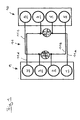
- Fig. 1 schematically shows an inventively designed exhaust system for an 8-cylinder engine in V-type.
- the internal combustion engine has a first cylinder bank 9 and a second cylinder bank 10 lying opposite the first cylinder bank 9.
- the first cylinder bank 9 has four cylinders 1, 2, 3, 4 arranged in series and the second cylinder bank 10 likewise has four cylinders 5, 6, 7, 8 arranged in series, the cylinders 1 and 5, 2 and 6, 3 and 7 and the cylinders 4 and 8 are arranged opposite to each other.
- a firing interval from cylinder to cylinder is nominally 90 °, wherein in a technical realization of the invention, depending on the operating condition of the internal combustion engine, the firing interval of 85 ° to 95 ° can vary.
- the exhaust system 11 is composed of a first exhaust line 11a, a second exhaust line 11b, a third exhaust line 11c and a fourth exhaust line 11d.
- the first exhaust gas line 11a connects the cylinders 1 and 6 with one another leading to exhaust gas and opens into a first exhaust gas inlet (first flow) of a first exhaust gas turbocharger, not shown.
- the fourth exhaust gas line 11d connects the cylinders 4 and 7 with one another in exhaust gas and opens into a second exhaust gas inlet (second flow) of the first exhaust gas turbocharger.
- the second exhaust line 11b connects the cylinders 2 and 5 exhaust gas leading together and opens into a first exhaust gas inlet (third flood) of a second exhaust gas turbocharger, not shown.
- the third exhaust gas line 11c connects the cylinders 3 and 8 exhaust gas leading together and opens into a second exhaust gas inlet (fourth flood) of the second exhaust gas turbocharger.
- the first and the second exhaust gas turbocharger are each a twin-scroll exhaust gas turbocharger.
- exhaust gas turbocharger with two exhaust gas turbines, each with its own flood.
- the exhaust gas turbocharger in the V between the cylinder banks 9 and 10 are arranged, in another embodiment, the exhaust gas turbocharger but also outside, that can be arranged in front of and / or behind or laterally to the internal combustion engine.
- the exhaust system 11 is preferably manufactured as a sheet-metal component, again preferably in air-gap-insulated design.
- the production as a cast component is possible, but this leads to weight disadvantages. Accordingly, a composite construction as a combined sheet metal / cast component is possible.
- a version as a liquid-cooled light metal exhaust system is possible.
- the cooling is preferably carried out with a Coolant of the internal combustion engine, wherein preferably an aluminum alloy is used as light metal.
- each turbine of the exhaust gas turbocharger "sees" a firing interval of 180 ° crank angle. Depending on the operating state of the internal combustion engine, this ignition interval can also vary by +/- 5 °. This is the maximum attainable ignition distance for an internal combustion engine with 8 cylinders. This maximum ignition interval leads to an optimum of the charge exchange, since an exactly symmetrical, equal filling for all cylinders 1, 2, 3, 4, 5, 6, 7, 8 is achieved. Next remains less residual gas in the cylinders 1, 2, 3, 4, 5, 6, 7, 8, resulting in a lower tendency to knock the engine.
- the extended opening period of the gas exchange inlet valves or the camshaft whereby a significantly higher performance, and a higher torque of the internal combustion engine can be achieved.
- the fuel consumption in the area of full load is also significantly improved.
- Another major advantage is achieved at low speeds, since at very low speeds already very high torques of the internal combustion engine can be achieved.
- a "turbo lag" a weak torque in the lower speed range, can be significantly minimized, so that this weakness in practical driving no longer appears.
- a very uniform exhaust gas emissions of the turbines is achieved, whereby their life is significantly extended.
Description
- Die Erfindung betrifft eine Brennkraftmaschine mit den Merkmalen aus dem Oberbegriff des Patentanspruchs 1, wie sie z.B. in der
EP 1662109 gezeigt ist. - Einen weiteren Stand der Technik zeigt die deutsche Offenlegungsschrift
DE 10 2004 057 129 A1 . Aus dieser Offenlegungsschrift ist eine Brennkraftmaschine in V-Bauart mit 8 Zylindern bekannt, mit einer Zündfolge von 90° Kurbelwinkel von Zylinder zu Zylinder. Jede Zylinderbank der Brennkraftmaschine weist vier Zylinder auf. Jeweils zwei Zylinder einer Zylinderbank münden in einen Abgasstrang, der jeweils die Abgase der vier zugeordneten Zylinder in einen Abgasturbolader leitet. Somit weist die Brennkraftmaschine zwei vierflutige Abgasstränge auf. Beide Abgasstrange bilden miteinander eine Abgasanlage. Vor dem Eintritt in die Turbolader, sind die Abgasstränge abgasführend miteinander verbindbar. In Strömungsrichtung des Abgases ist nach jedem Abgasturbolader jeweils eine Abgasreinigungsanlage in der Abgasanlage angeordnet. - Nachteilig an der beschriebenen Ausgestaltung ist ein sog. Übersprechen der Abgase der jeweils in einen Abgasstrang mündenden vier Zylinder, wodurch eine maximale Öffnungsdauer der Gaswechseleinlassventile nicht realisierbar ist.
- Aufgabe der vorliegenden Erfindung ist es, eine Maßnahme aufzuzeigen, die das Übersprechen der Abgase der vier, einem einzelnen Abgasstrang zugeordneten Zylinder zu verhindern.
- Diese Aufgabe wird durch die Merkmale im kennzeichnenden Teil des Patentanspruchs 1 gelöst.
- Durch die erfindungsgemäße Ausgestaltung beträgt der Zündabstand 360° Kurbelwinkel der zwei einem Abgasstrang, bzw. Flut zugeordneten Zylinder. Somit wird das Turbinenrad des Abgasturboladers mit Abgasen beaufschlagt mit 180° Zündabstand. Durch diese Ausgestaltung ist es erfindungsgemäß möglich, die Öffnungsdauer der Gaswechseleinlassventile gegenüber dem Stand der Technik zu verlängern, wodurch mehr Leistung und Drehmoment für die Brennkraftmaschine erzielt wird. Aufgrund der erfindungsgemäßen Ausgestaltung der Abgasanlage wird ein Optimum für den Ladungswechsel erzielt, weil eine symmetrische, gleiche Füllung mit Frischluft für alle acht Zylinder vorliegt. Durch die optimale symmetrische, gleiche Füllung verbleibt weniger Restgas in den einzelnen Zylindern, wodurch die Klopfneigung der Brennkraftmaschine wesentlich verbessert wird. Ferner ist der Brennstoffverbrauch, insbesondere bei Volllast der Brennkraftmaschine, besser. Darüber hinaus liegen bei sehr geringen Drehzahlen bereits schon sehr hohe Drehmomentwerte an. Hierdurch wird das sog. "Turboloch", eine Drehmomentschwäche im unteren Drehzahlbereich, praktisch fast vollständig eliminiert. In vorteilhafter Weise kann die erfindungsgemäße Abgasanlage sowohl für Brennkraftmaschinen die nach dem Otto-Prinzip arbeiten, als auch für Brennkraftmaschinen die nach dem Diesel-Prinzip arbeiten, zum Einsatz kommen.
- Durch die Ausgestaltung gemäß Patentanspruch 2 werden extrem kurze Wege für das Abgas in der Abgasanlage erzielt, was die Strömungsverluste des Abgases minimiert und der Emissionierung, sowie dem Brennstoffverbrauch zu Gute kommt.
- Die Ausgestaltung gemäß Patentanspruch 3 ist eine besonders bevorzugte Ausführungsvariante für einen zweiflutigen Abgasturbolader, wobei jede Flut von einem Abgasstrang mit Abgas beaufschlagt wird.
- Die Ausgestaltung gemäß Patentanspruch 4 ist eine zweite ebenfalls besonders bevorzugte Ausführungsvariante, bei der jeder Abgasturbolader zwei Abgasturbinen mit jeweils einer eigenen Flut aufweist, in die jeweils ein Abgasstrang mündet.
- Die Ausgestaltung gemäß der Patentansprüche 5 bis 8 sind besonders bevorzugte Ausführungs-, bzw. Herstellvarianten.
- Im Folgenden ist die Erfindung anhand eines besonders bevorzugten Ausführungsbeispieles schematisch in einer einzigen Figur näher erläutert.
-
Fig. 1 zeigt schematisch eine erfindungsgemäß ausgestaltete Abgasanlage für eine 8-zylindrige Brennkraftmaschine in V-Bauart. Die Brennkraftmaschine weist eine erste Zylinderbank 9 und eine zweite, der ersten Zylinderbank 9 gegenüber liegende Zylinderbank 10 auf. Die erste Zylinderbank 9 weist vier in Reihe angeordnete Zylinder 1, 2, 3, 4 und die zweite Zylinderbank 10 weist ebenfalls vier in Reihe angeordnete Zylinder 5, 6, 7, 8 auf, wobei die Zylinder 1 und 5, 2 und 6, 3 und 7 und die Zylinder 4 und 8 einander gegenüberliegend angeordnet sind. Ein Zündabstand von Zylinder zu Zylinder beträgt nominell 90°, wobei bei einer technischen Realisierung der Erfindung, abhängig vom Betriebszustand der Brennkraftmaschine, der Zündabstand von 85° bis 95° variieren kann. - Zwischen den Zylinderbänken 9 und 10, d. h. im V, sind zwei nicht dargestellte Abgasturbolader anordenbar, die über eine Abgasanlage 11 mit den Zylindern 1, 2, 3, 4, 5, 6, 7, 8 gasführend miteinander verbindbar sind. Die Abgasanlage 11 ist aus einem ersten Abgasstrang 11a, einem zweiten Abgasstrang 11b, einem dritten Abgasstrang 11c sowie einem vierten Abgasstrang 11d aufgebaut. Der erste Abgasstrang 11a verbindet die Zylinder 1 und 6 abgasführend miteinander und mündet in einen ersten Abgaseintritt (erste Flut) eines ersten nicht dargestellten Abgasturbolader. Der vierte Abgasstrang 11d verbindet die Zylinder 4 und 7 abgasführend miteinander und mündet in einen zweiten Abgaseintritt (zweite Flut) des ersten Abgasturboladers. Der zweite Abgasstrang 11b verbindet die Zylinder 2 und 5 abgasführend miteinander und mündet in einen ersten Abgaseintritt (dritte Flut) eines zweiten nicht dargestellten Abgasturboladers. Der dritte Abgasstrang 11c verbindet die Zylinder 3 und 8 abgasführend miteinander und mündet in einen zweiten Abgaseintritt (vierte Flut) des zweiten Abgasturboladers.
- Bevorzugt sind der erste und dem zweite Abgasturbolader jeweils ein Twin-Scroll-Abgasturbolader. Alternativ ist es auch möglich, Abgasturbolader mit zwei Abgasturbinen mit jeweils einer eigenen Flut einzusetzen.
- Im vorliegenden Ausführungsbeispiel sind die Abgasturbolader im V zwischen den Zylinderbänken 9 und 10 angeordnet, in einem anderen Ausführungsbeispiel können die Abgasturbolader jedoch auch außen, d. h. vor und/oder hinter oder seitlich an die Brennkraftmaschine angeordnet sein. Aus Gewichtsgründen wird die Abgasanlage 11 bevorzugt als Blechbauteil, wiederum bevorzugt in luftspaltisolierter Ausführung, gefertigt. Auch die Fertigung als Gussbauteil ist möglich, was jedoch zu Gewichtsnachteilen führt. Entsprechend ist auch eine Verbundbauweise als kombiniertes Blech/Gussbauteil möglich. Auch eine Ausführung als flüssigkeitsgekühlte Leichtmetallabgasanlage ist möglich. Die Kühlung erfolgt hierbei vorzugsweise mit einem Kühlmittel der Brennkraftmaschine, wobei vorzugsweise als Leichtmetall eine Aluminiumlegierung verwendet wird.
- Die Verwendung der erfindungsgemäßen Abgasanlage ist an jeder 8-zylindrigen Brennkraftmaschine die im 4-Takt arbeitet möglich, egal ob diese nach dem Otto- oder Dieselbrennverfahren arbeitet.
- Durch die erfindungsgemäße Ausgestaltung der Abgasanlage "sieht" jede Turbine der Abgasturbolader einen Zündabstand von 180° Kurbelwinkel. Abhängig vom Betriebszustand der Brennkraftmaschine kann dieser Zündabstand auch um +/- 5° variieren. Dies ist der maximal erzielbare Zündabstand für eine Brennkraftmaschine mit 8 Zylindern. Dieser maximale Zündabstand führt zu einem Optimum des Ladungswechsels, da eine exakt symmetrische, gleiche Füllung für alle Zylinder 1, 2, 3, 4, 5, 6, 7, 8 erzielt wird. Weiter verbleibt weniger Restgas in den Zylindern 1, 2, 3, 4, 5, 6, 7, 8, was zu einer geringeren Klopfneigung der Brennkraftmaschine führt. Besonders hervorzuheben ist die verlängerte Öffnungsdauer der Gaswechseleinlassventile bzw. der Nockenwelle, wodurch eine deutlich höhere Leistung, sowie ein höheres Drehmoment der Brennkraftmaschine erzielt werden. Neben der Leistungssteigerung ist auch der Brennstoffverbrauch im Bereich der Volllast deutlich verbessert. Ein weiterer Hauptvorteil wird bei niedrigen Drehzahlen erzielt, da bei sehr niedrigen Drehzahlen bereits sehr hohe Drehmomente der Brennkraftmaschine erreicht werden. Hierdurch kann ein "Turboloch", eine Drehmomentschwäche im unteren Drehzahlbereich, deutlich minimiert werden, so dass diese Schwäche im praktischen Fahrbetrieb nicht mehr in Erscheinung tritt. Darüber hinaus wird eine äußerst gleichmäßige Abgasbeaufschlagung der Turbinen erzielt, wodurch deren Lebensdauer deutlich verlängert wird.
-
- 1.
- erster Zylinder
- 2.
- zweiter Zylinder
- 3.
- dritter Zylinder
- 4.
- vierter Zylinder
- 5.
- fünfter Zylinder
- 6.
- sechster Zylinder
- 7.
- siebter Zylinder
- 8.
- achter Zylinder
- 9.
- erste
- 10.
- zweite Zylinderbank
- 11.
- Abgasanlage
- 11a
- erster Abgasstrang
- 11b
- zweiter Abgasstrang
- 11c
- dritter Abgasstrang
- 11d
- vierter Abgasstrang
Claims (8)
- Brennkraftmaschine mit acht Zylindern in V-Bauart mit einer Abgasanlage (11) mit einem ersten und einem zweiten Abgasturbolader
wobei von einem ersten, einem zweiten, einem dritten und einem vierten, in Reihe nebeneinander angeordneten Zylinder (1, 2, 3, 4) eine erste Zylinderbank (9) und von einem fünften, einem sechsten, einem siebten und einem achten, in Reihe nebeneinander angeordneten Zylinder (5, 6, 7, 8) eine zweite, der ersten Zylinderbank (9) gegenüberliegende Zylinderbank (10) gebildet ist, wobei die Brennkraftmaschine von Zylinder von Zylinder eine Zündfolge von 90° Kurbelwinkel aufweist,
wobei
die Abgasanlage (11) einen ersten, einen zweiten, einen dritten und einen vierten Abgasstrang (11a, 11b, 11c, 11d) von den Zylindern (1, 2, 3, 4, 5, 6, 7, 8) zu den zwei Abgasturboladern aufweist, und
wobei einem Abgasstrang (11a, 11b, 11c, 11d) jeweils zwei Zylinder (1, 2, 3, 4, 5, 6, 7, 8) und zwei Abgassträngen (11a, 11b, 11c, 11d) jeweils ein Abgasturbolader zugeordnet ist,
dadurch gekennzeichnet, dass- zwei, einem Abgasstrang (11a, 11b, 11c, 11d) zugeordnete Zylinder (1, 2, 3, 4, 5, 6, 7, 8) einen Zündabstand von 360° Kurbelwinkel aufweisen und- dass der erste und der zweite, einem Abgasturbolader zugeordnete Abgasstrang (11a, 11b, 11c, 11d) eine um 180° Kurbelwinkel zueinander verschobene Zündfolge aufweist. - Brennkraftmaschine mit einer Abgasanlage nach Patentanspruch 1,
dadurch gekennzeichnet, dass die Abgasanlage (11) und die zwei Abgasturbolader weitgehend im V zwischen den Zylinderbänken (9, 10) angeordnet sind. - Brennkraftmaschine mit einer Abgasanlage nach Patentanspruch 1 oder 2,
dadurch gekennzeichnet, dass der erste und der zweite Turbolader Twin-Scroll-Turbolader sind. - Brennkraftmaschine mit einer Abgasanlage nach Patentanspruch 1 oder 2, wobei der erste Abgasturbolader ein erstes Turbinenrad und der zweite Abgasturbolader ein zweites Turbinenrad aufweist,
dadurch gekennzeichnet, dass der erste Turbolader ein drittes Turbinenrad und der zweite Turbolader ein viertes Turbinenrad aufweist. - Brennkraftmaschine mit einer Abgasanlage nach einem der Patentansprüche 1 bis 4,
dadurch gekennzeichnet, dass die Abgasanlage (11) als ein Blechbauteil gefertigt ist. - Brennkraftmaschine mit einer Abgasanlage nach einem der Patentansprüche 1 bis 4,
dadurch gekennzeichnet, dass die Abgasanlage (11) als ein Gussbauteil gefertigt ist. - Brennkraftmaschine mit einer Abgasanlage nach einem der Patentansprüche 1 bis 4,
dadurch gekennzeichnet, dass die Abgasanlage (11) in einer Verbundbauweise als ein kombiniertes Blech- und Gussbauteil gefertigt ist. - Brennkraftmaschine mit einer Abgasanlage nach einem der Patentansprüche 1 bis 4,
dadurch gekennzeichnet, dass die Abgasanlage (11) eine flüssigkeitsgekühlte Leichtmetallabgasanlage ist.
Applications Claiming Priority (2)
| Application Number | Priority Date | Filing Date | Title |
|---|---|---|---|
| DE102007006699A DE102007006699A1 (de) | 2007-02-10 | 2007-02-10 | Abgasanlage für eine Brennkraftmaschine |
| PCT/EP2008/000827 WO2008095656A1 (de) | 2007-02-10 | 2008-02-01 | Abgasanlage für eine brennkraftmaschine |
Publications (2)
| Publication Number | Publication Date |
|---|---|
| EP2115284A1 EP2115284A1 (de) | 2009-11-11 |
| EP2115284B1 true EP2115284B1 (de) | 2010-08-04 |
Family
ID=39325609
Family Applications (1)
| Application Number | Title | Priority Date | Filing Date |
|---|---|---|---|
| EP08707510A Active EP2115284B1 (de) | 2007-02-10 | 2008-02-01 | Brennkraftmaschine mit einer abgasanlage |
Country Status (6)
| Country | Link |
|---|---|
| US (1) | US7950229B2 (de) |
| EP (1) | EP2115284B1 (de) |
| JP (1) | JP5114500B2 (de) |
| AT (1) | ATE476591T1 (de) |
| DE (2) | DE102007006699A1 (de) |
| WO (1) | WO2008095656A1 (de) |
Cited By (2)
| Publication number | Priority date | Publication date | Assignee | Title |
|---|---|---|---|---|
| DE102017210582A1 (de) | 2017-06-23 | 2018-12-27 | Bayerische Motoren Werke Aktiengesellschaft | Brennkraftmaschine |
| DE102018215119B3 (de) * | 2018-09-06 | 2019-11-28 | Bayerische Motoren Werke Aktiengesellschaft | V8-Cross-Plane-Brennkraftmaschine und Betriebsverfahren |
Families Citing this family (5)
| Publication number | Priority date | Publication date | Assignee | Title |
|---|---|---|---|---|
| DE102007058296A1 (de) * | 2007-12-05 | 2009-06-10 | Audi Ag | Brennkraftmaschine mit einem Abgasturbolader |
| US9303555B2 (en) * | 2013-04-04 | 2016-04-05 | GM Global Technology Operations LLC | Exhaust manifold |
| DE102015113806A1 (de) * | 2015-08-20 | 2017-02-23 | Dr. Ing. H.C. F. Porsche Aktiengesellschaft | Brennkraftmaschine und Verfahren zum Betrieb einer Brennkraftmaschine |
| DE102017220191A1 (de) | 2017-11-14 | 2019-05-16 | Bayerische Motoren Werke Aktiengesellschaft | Brennkraftmaschine und Verfahren zum Betreiben der Brennkraftmaschine |
| DE102017220192A1 (de) | 2017-11-14 | 2019-05-16 | Bayerische Motoren Werke Aktiengesellschaft | Brennkraftmaschine und Verfahren zum Betreiben der Brennkraftmaschine |
Family Cites Families (35)
| Publication number | Priority date | Publication date | Assignee | Title |
|---|---|---|---|---|
| FR696140A (fr) * | 1929-06-04 | 1930-12-26 | Turbines à deux ou à plusieurs injections en couronne, avec distributeurs ramiflés | |
| DE1025211B (de) * | 1954-02-13 | 1958-02-27 | Maschf Augsburg Nuernberg Ag | Auspuffleitung |
| DE1043707B (de) * | 1954-12-31 | 1958-11-13 | Krauss Maffei Ag | Brennkraftmaschine mit V-foermig angeordneten Zylindern |
| US3524315A (en) | 1967-04-21 | 1970-08-18 | Daimler Benz Ag | Exhaust gas line serving for the feed of exhaust gas turbochargers |
| BE759780A (fr) * | 1969-12-04 | 1971-05-17 | Bbc Brown Boveri & Cie | Procede et dispositif pour suralimentation par impulsions d'un moteur acombustion interne |
| US3775151A (en) * | 1970-05-06 | 1973-11-27 | Nat Steel Corp | Process for preparing chromized ferrous metal sheet material and the resultant articles |
| US3718172A (en) * | 1971-07-16 | 1973-02-27 | Gen Motors Corp | Method of forming a thermally insulated composite article |
| US4058485A (en) * | 1974-12-26 | 1977-11-15 | Union Carbide Corporation | Porous metal-alumina composite |
| DE3138369C1 (de) * | 1981-09-26 | 1983-03-10 | Daimler-Benz Ag, 7000 Stuttgart | Aufladesystem für eine mehrzylindrige Brennkraftmaschine |
| JPH0515536Y2 (de) * | 1986-10-31 | 1993-04-23 | ||
| DE4030652A1 (de) * | 1990-09-28 | 1992-04-09 | Daimler Benz Ag | Verbrennungsmotor mit in v-form angeordneten zylinderbaenken |
| JPH05149142A (ja) * | 1991-11-25 | 1993-06-15 | Hino Motors Ltd | 排気ターボ過給機付v型多気筒エンジンの排気装置 |
| DE4310272A1 (de) * | 1993-03-30 | 1994-10-06 | Emil Heinrich Friedrich | Verfahren zur Herstellung von mehrschichtigen Verbundrohren mit Metalleinlagen |
| FR2712922B1 (fr) * | 1993-11-22 | 1996-01-05 | Remi Curtil | Procédé pour améliorer le fonctionnement d'un moteur thermique suralimenté et balayé avec de l'air, et moteur thermique agencé pour la mise en Óoeuvre du procédé. |
| DE4342572C1 (de) * | 1993-12-14 | 1994-11-24 | Mtu Friedrichshafen Gmbh | Abgasanlage für eine aufgeladene Brennkraftmaschine |
| DE19539572A1 (de) | 1995-10-25 | 1997-04-30 | Asea Brown Boveri | Abgasleitungssystem für eine turboaufgeladene Viertakt-Brennkraftmaschine |
| US5816043A (en) * | 1996-01-02 | 1998-10-06 | Acoust-A-Fiber Research And Development, Inc. | Shield encompassing a hot pipe |
| JPH1030446A (ja) * | 1996-07-17 | 1998-02-03 | Nissan Diesel Motor Co Ltd | エンジンの過給装置 |
| US6293311B1 (en) * | 1998-05-22 | 2001-09-25 | Pmd Holdings Corp. | Multilayer composite pipe fluid conduit system using multilayer composite pipe and method of making the composite |
| DE19826355A1 (de) * | 1998-06-12 | 1999-12-16 | Daimler Chrysler Ag | Vorrichtung und Verfahren zur Steuerung einer Abgasturboladerturbine |
| DE10015291A1 (de) * | 2000-03-28 | 2001-10-04 | Daimler Chrysler Ag | Mehrzylindrige Hubkolbenbrennkraftmaschine |
| JP3936849B2 (ja) * | 2001-05-16 | 2007-06-27 | スズキ株式会社 | フェライト系球状黒鉛鋳鉄及びこれを用いた排気系部品 |
| DE10207077A1 (de) * | 2002-02-20 | 2003-02-06 | Christian Puchas | Kurbelwellen für eine V-Motoren-Baureihe |
| DE10346552A1 (de) * | 2003-10-07 | 2005-06-30 | Friedrich Boysen Gmbh & Co. Kg | Luftspaltkrümmer |
| JP2005163752A (ja) * | 2003-12-05 | 2005-06-23 | Toyota Industries Corp | 多気筒エンジンの吸排気装置 |
| DE102004054726A1 (de) * | 2004-11-12 | 2006-06-08 | Daimlerchrysler Ag | Aufgeladene Brennkraftmaschine |
| DE102004057130A1 (de) * | 2004-11-26 | 2006-06-08 | Bayerische Motoren Werke Ag | Verfahren zum Betrieb einer mager betreibbaren Brennkraftmaschine |
| DE102004057129A1 (de) | 2004-11-26 | 2006-06-01 | Bayerische Motoren Werke Ag | Abgasanlage für eine Brennkraftmaschine |
| JP2006307677A (ja) * | 2005-04-26 | 2006-11-09 | Mitsubishi Heavy Ind Ltd | 過給機付きエンジンの減筒運転装置及び減筒運転方法 |
| JP2007032394A (ja) * | 2005-07-26 | 2007-02-08 | Hino Motors Ltd | V型エンジン |
| AT500458B1 (de) * | 2005-09-27 | 2007-05-15 | Avl List Gmbh | Brennkraftmaschine, insbesondere otto-brennkraftmaschine |
| DE102005047890A1 (de) * | 2005-10-06 | 2007-05-03 | Bayerische Motoren Werke Ag | Abgaskrümmer für eine 8-Zylinder-Brennkraftmaschine |
| WO2008015583A1 (en) * | 2006-06-13 | 2008-02-07 | Wescast Industries, Inc. | Exhaust manifolds including heat shield assemblies |
| DE102006042464A1 (de) * | 2006-09-09 | 2008-03-27 | Audi Ag | Verbrennungsmotor mit Abgasturboladeranordnung und Verfahren zum Betreiben eines Verbrennungsmotors und Abgasturboladeranordnung |
| JP2009191699A (ja) * | 2008-02-13 | 2009-08-27 | Toyota Motor Corp | 内燃機関の排気装置 |
-
2007
- 2007-02-10 DE DE102007006699A patent/DE102007006699A1/de not_active Withdrawn
-
2008
- 2008-02-01 WO PCT/EP2008/000827 patent/WO2008095656A1/de active Application Filing
- 2008-02-01 AT AT08707510T patent/ATE476591T1/de active
- 2008-02-01 EP EP08707510A patent/EP2115284B1/de active Active
- 2008-02-01 JP JP2009548611A patent/JP5114500B2/ja active Active
- 2008-02-01 DE DE502008001078T patent/DE502008001078D1/de active Active
-
2009
- 2009-08-07 US US12/537,768 patent/US7950229B2/en active Active
Cited By (4)
| Publication number | Priority date | Publication date | Assignee | Title |
|---|---|---|---|---|
| DE102017210582A1 (de) | 2017-06-23 | 2018-12-27 | Bayerische Motoren Werke Aktiengesellschaft | Brennkraftmaschine |
| WO2018233974A1 (de) | 2017-06-23 | 2018-12-27 | Bayerische Motoren Werke Aktiengesellschaft | Brennkraftmaschine |
| US10927751B2 (en) | 2017-06-23 | 2021-02-23 | Bayerische Motoren Werke Aktiengesellschaft | Internal combustion engine |
| DE102018215119B3 (de) * | 2018-09-06 | 2019-11-28 | Bayerische Motoren Werke Aktiengesellschaft | V8-Cross-Plane-Brennkraftmaschine und Betriebsverfahren |
Also Published As
| Publication number | Publication date |
|---|---|
| DE102007006699A1 (de) | 2008-08-14 |
| JP2010518305A (ja) | 2010-05-27 |
| DE502008001078D1 (de) | 2010-09-16 |
| ATE476591T1 (de) | 2010-08-15 |
| JP5114500B2 (ja) | 2013-01-09 |
| EP2115284A1 (de) | 2009-11-11 |
| US20100031905A1 (en) | 2010-02-11 |
| WO2008095656A1 (de) | 2008-08-14 |
| US7950229B2 (en) | 2011-05-31 |
Similar Documents
| Publication | Publication Date | Title |
|---|---|---|
| EP2115284B1 (de) | Brennkraftmaschine mit einer abgasanlage | |
| DE102007034240B4 (de) | Einlasskrümmeranordnung | |
| EP1275832B1 (de) | Vorrichtung zur mehrstufigen Aufladung einer Brennkraftmaschine | |
| AT500458B1 (de) | Brennkraftmaschine, insbesondere otto-brennkraftmaschine | |
| EP2532869B1 (de) | Brennkraftmaschine mit mindestens vier in Reihe angeordneten Zylindern | |
| DE102014201066A1 (de) | Aufgeladene Brennkraftmaschine mit zweiflutiger Turbine und Verfahren zum Betreiben einer derartigen Brennkraftmaschine | |
| EP2496805B1 (de) | V-motor | |
| EP2146072A1 (de) | Brennkraftmaschine mit Zylinderkopf und Turbine | |
| DE102009027203A1 (de) | Aufgeladene Brennkraftmaschine mit mindestens vier Zylindern und einer zweiflutigen Turbine und Verfahren zum Betreiben einer derartigen Brennkraftmaschine | |
| DE102012213936A1 (de) | Aufgeladener Vier-Zylinder-Reihenmotor mit parallel angeordneten Turbinen und Verfahren zum Betreiben eines derartigen Vier-Zylinder-Reihenmotors | |
| DE102008055896A1 (de) | Turboladeranordnung für eine Brennkraftmaschine | |
| DE102006042464A1 (de) | Verbrennungsmotor mit Abgasturboladeranordnung und Verfahren zum Betreiben eines Verbrennungsmotors und Abgasturboladeranordnung | |
| EP3642463B1 (de) | Brennkraftmaschine | |
| DE102008049091A1 (de) | Verfahren zum Betreiben einer Brennkraftmaschine mit acht Zylindern und Brennkraftmaschine | |
| WO2006050896A1 (de) | Aufgeladene brennkraftmaschine | |
| DE102018215119B3 (de) | V8-Cross-Plane-Brennkraftmaschine und Betriebsverfahren | |
| DE102006042463A1 (de) | Verbrennungsmotor mit Abgasturbolader und Verfahren zum Betreiben eines Verbrennungsmotors mit Abgasturbolader | |
| DE102012103013B4 (de) | Brennkraftmaschine mit Abgasturbolader | |
| EP3483407B1 (de) | Brennkraftmaschine und verfahren zum betreiben der brennkraftmaschine | |
| DE202013102078U1 (de) | Aufgeladene Brennkraftmaschine mit abschaltbarem Zylinder | |
| DE102019126350B3 (de) | Brennkraftmaschine eines Kraftfahrzeugs und Verfahren zum Betreiben derselben | |
| DE102015205996B4 (de) | Verfahren zum Betreiben einer aufgeladenen selbstzündenden Vier-Zylinder-Brennkraftmaschine mit zweiflutiger Turbine | |
| DE102015205324A1 (de) | Drei-Zylinder-Brennkraftmaschine mit Zylinderabschaltung und Verfahren zum Betreiben einer derartigen Drei-Zylinder-Brennkraftmaschine | |
| DE102014215844B4 (de) | Abgasturboaufgeladene Brennkraftmaschine mit Radialturbine und gruppierten Zylindern und Verfahren zum Betreiben einer derartigen Brennkraftmaschine | |
| DE102014208289A1 (de) | Aufgeladene fremdgezündete Brennkraftmaschine mit abschaltbarem Zylinder und Verfahren zum Betreiben einer derartigen Brennkraftmaschine |
Legal Events
| Date | Code | Title | Description |
|---|---|---|---|
| PUAI | Public reference made under article 153(3) epc to a published international application that has entered the european phase |
Free format text: ORIGINAL CODE: 0009012 |
|
| 17P | Request for examination filed |
Effective date: 20090617 |
|
| AK | Designated contracting states |
Kind code of ref document: A1 Designated state(s): AT BE BG CH CY CZ DE DK EE ES FI FR GB GR HR HU IE IS IT LI LT LU LV MC MT NL NO PL PT RO SE SI SK TR |
|
| GRAP | Despatch of communication of intention to grant a patent |
Free format text: ORIGINAL CODE: EPIDOSNIGR1 |
|
| GRAJ | Information related to disapproval of communication of intention to grant by the applicant or resumption of examination proceedings by the epo deleted |
Free format text: ORIGINAL CODE: EPIDOSDIGR1 |
|
| GRAC | Information related to communication of intention to grant a patent modified |
Free format text: ORIGINAL CODE: EPIDOSCIGR1 |
|
| GRAP | Despatch of communication of intention to grant a patent |
Free format text: ORIGINAL CODE: EPIDOSNIGR1 |
|
| RTI1 | Title (correction) |
Free format text: INTERNAL COMBUSTION ENGINE WITH AN EXHAUST GAS SYSTEM |
|
| DAX | Request for extension of the european patent (deleted) | ||
| RIC1 | Information provided on ipc code assigned before grant |
Ipc: F02B 37/007 20060101ALI20100303BHEP Ipc: F01N 13/10 20100101ALI20100303BHEP Ipc: F02B 37/02 20060101AFI20100303BHEP Ipc: F01N 13/08 20100101ALI20100303BHEP |
|
| GRAS | Grant fee paid |
Free format text: ORIGINAL CODE: EPIDOSNIGR3 |
|
| GRAA | (expected) grant |
Free format text: ORIGINAL CODE: 0009210 |
|
| AK | Designated contracting states |
Kind code of ref document: B1 Designated state(s): AT BE BG CH CY CZ DE DK EE ES FI FR GB GR HR HU IE IS IT LI LT LU LV MC MT NL NO PL PT RO SE SI SK TR |
|
| REG | Reference to a national code |
Ref country code: GB Ref legal event code: FG4D Free format text: NOT ENGLISH |
|
| REG | Reference to a national code |
Ref country code: CH Ref legal event code: EP |
|
| REG | Reference to a national code |
Ref country code: IE Ref legal event code: FG4D Free format text: LANGUAGE OF EP DOCUMENT: GERMAN |
|
| REF | Corresponds to: |
Ref document number: 502008001078 Country of ref document: DE Date of ref document: 20100916 Kind code of ref document: P |
|
| REG | Reference to a national code |
Ref country code: NL Ref legal event code: VDEP Effective date: 20100804 |
|
| LTIE | Lt: invalidation of european patent or patent extension |
Effective date: 20100804 |
|
| PG25 | Lapsed in a contracting state [announced via postgrant information from national office to epo] |
Ref country code: LT Free format text: LAPSE BECAUSE OF FAILURE TO SUBMIT A TRANSLATION OF THE DESCRIPTION OR TO PAY THE FEE WITHIN THE PRESCRIBED TIME-LIMIT Effective date: 20100804 Ref country code: FI Free format text: LAPSE BECAUSE OF FAILURE TO SUBMIT A TRANSLATION OF THE DESCRIPTION OR TO PAY THE FEE WITHIN THE PRESCRIBED TIME-LIMIT Effective date: 20100804 Ref country code: NL Free format text: LAPSE BECAUSE OF FAILURE TO SUBMIT A TRANSLATION OF THE DESCRIPTION OR TO PAY THE FEE WITHIN THE PRESCRIBED TIME-LIMIT Effective date: 20100804 Ref country code: NO Free format text: LAPSE BECAUSE OF FAILURE TO SUBMIT A TRANSLATION OF THE DESCRIPTION OR TO PAY THE FEE WITHIN THE PRESCRIBED TIME-LIMIT Effective date: 20101104 |
|
| PG25 | Lapsed in a contracting state [announced via postgrant information from national office to epo] |
Ref country code: HR Free format text: LAPSE BECAUSE OF FAILURE TO SUBMIT A TRANSLATION OF THE DESCRIPTION OR TO PAY THE FEE WITHIN THE PRESCRIBED TIME-LIMIT Effective date: 20100804 Ref country code: CY Free format text: LAPSE BECAUSE OF FAILURE TO SUBMIT A TRANSLATION OF THE DESCRIPTION OR TO PAY THE FEE WITHIN THE PRESCRIBED TIME-LIMIT Effective date: 20100804 Ref country code: IS Free format text: LAPSE BECAUSE OF FAILURE TO SUBMIT A TRANSLATION OF THE DESCRIPTION OR TO PAY THE FEE WITHIN THE PRESCRIBED TIME-LIMIT Effective date: 20101204 Ref country code: PL Free format text: LAPSE BECAUSE OF FAILURE TO SUBMIT A TRANSLATION OF THE DESCRIPTION OR TO PAY THE FEE WITHIN THE PRESCRIBED TIME-LIMIT Effective date: 20100804 Ref country code: SI Free format text: LAPSE BECAUSE OF FAILURE TO SUBMIT A TRANSLATION OF THE DESCRIPTION OR TO PAY THE FEE WITHIN THE PRESCRIBED TIME-LIMIT Effective date: 20100804 Ref country code: BG Free format text: LAPSE BECAUSE OF FAILURE TO SUBMIT A TRANSLATION OF THE DESCRIPTION OR TO PAY THE FEE WITHIN THE PRESCRIBED TIME-LIMIT Effective date: 20101104 |
|
| REG | Reference to a national code |
Ref country code: IE Ref legal event code: FD4D |
|
| PG25 | Lapsed in a contracting state [announced via postgrant information from national office to epo] |
Ref country code: SE Free format text: LAPSE BECAUSE OF FAILURE TO SUBMIT A TRANSLATION OF THE DESCRIPTION OR TO PAY THE FEE WITHIN THE PRESCRIBED TIME-LIMIT Effective date: 20100804 Ref country code: GR Free format text: LAPSE BECAUSE OF FAILURE TO SUBMIT A TRANSLATION OF THE DESCRIPTION OR TO PAY THE FEE WITHIN THE PRESCRIBED TIME-LIMIT Effective date: 20101105 Ref country code: LV Free format text: LAPSE BECAUSE OF FAILURE TO SUBMIT A TRANSLATION OF THE DESCRIPTION OR TO PAY THE FEE WITHIN THE PRESCRIBED TIME-LIMIT Effective date: 20100804 |
|
| PG25 | Lapsed in a contracting state [announced via postgrant information from national office to epo] |
Ref country code: DK Free format text: LAPSE BECAUSE OF FAILURE TO SUBMIT A TRANSLATION OF THE DESCRIPTION OR TO PAY THE FEE WITHIN THE PRESCRIBED TIME-LIMIT Effective date: 20100804 Ref country code: IE Free format text: LAPSE BECAUSE OF FAILURE TO SUBMIT A TRANSLATION OF THE DESCRIPTION OR TO PAY THE FEE WITHIN THE PRESCRIBED TIME-LIMIT Effective date: 20100804 |
|
| PG25 | Lapsed in a contracting state [announced via postgrant information from national office to epo] |
Ref country code: CZ Free format text: LAPSE BECAUSE OF FAILURE TO SUBMIT A TRANSLATION OF THE DESCRIPTION OR TO PAY THE FEE WITHIN THE PRESCRIBED TIME-LIMIT Effective date: 20100804 Ref country code: EE Free format text: LAPSE BECAUSE OF FAILURE TO SUBMIT A TRANSLATION OF THE DESCRIPTION OR TO PAY THE FEE WITHIN THE PRESCRIBED TIME-LIMIT Effective date: 20100804 Ref country code: SK Free format text: LAPSE BECAUSE OF FAILURE TO SUBMIT A TRANSLATION OF THE DESCRIPTION OR TO PAY THE FEE WITHIN THE PRESCRIBED TIME-LIMIT Effective date: 20100804 Ref country code: RO Free format text: LAPSE BECAUSE OF FAILURE TO SUBMIT A TRANSLATION OF THE DESCRIPTION OR TO PAY THE FEE WITHIN THE PRESCRIBED TIME-LIMIT Effective date: 20100804 |
|
| PLBE | No opposition filed within time limit |
Free format text: ORIGINAL CODE: 0009261 |
|
| STAA | Information on the status of an ep patent application or granted ep patent |
Free format text: STATUS: NO OPPOSITION FILED WITHIN TIME LIMIT |
|
| PG25 | Lapsed in a contracting state [announced via postgrant information from national office to epo] |
Ref country code: ES Free format text: LAPSE BECAUSE OF FAILURE TO SUBMIT A TRANSLATION OF THE DESCRIPTION OR TO PAY THE FEE WITHIN THE PRESCRIBED TIME-LIMIT Effective date: 20101115 |
|
| 26N | No opposition filed |
Effective date: 20110506 |
|
| BERE | Be: lapsed |
Owner name: BAYERISCHE MOTOREN WERKE A.G. Effective date: 20110228 |
|
| REG | Reference to a national code |
Ref country code: DE Ref legal event code: R097 Ref document number: 502008001078 Country of ref document: DE Effective date: 20110506 |
|
| PG25 | Lapsed in a contracting state [announced via postgrant information from national office to epo] |
Ref country code: MC Free format text: LAPSE BECAUSE OF NON-PAYMENT OF DUE FEES Effective date: 20110228 |
|
| PG25 | Lapsed in a contracting state [announced via postgrant information from national office to epo] |
Ref country code: BE Free format text: LAPSE BECAUSE OF NON-PAYMENT OF DUE FEES Effective date: 20110228 |
|
| PG25 | Lapsed in a contracting state [announced via postgrant information from national office to epo] |
Ref country code: MT Free format text: LAPSE BECAUSE OF FAILURE TO SUBMIT A TRANSLATION OF THE DESCRIPTION OR TO PAY THE FEE WITHIN THE PRESCRIBED TIME-LIMIT Effective date: 20100804 |
|
| REG | Reference to a national code |
Ref country code: CH Ref legal event code: PL |
|
| PG25 | Lapsed in a contracting state [announced via postgrant information from national office to epo] |
Ref country code: CH Free format text: LAPSE BECAUSE OF NON-PAYMENT OF DUE FEES Effective date: 20120229 Ref country code: LI Free format text: LAPSE BECAUSE OF NON-PAYMENT OF DUE FEES Effective date: 20120229 |
|
| PG25 | Lapsed in a contracting state [announced via postgrant information from national office to epo] |
Ref country code: LU Free format text: LAPSE BECAUSE OF NON-PAYMENT OF DUE FEES Effective date: 20110201 |
|
| PG25 | Lapsed in a contracting state [announced via postgrant information from national office to epo] |
Ref country code: PT Free format text: LAPSE BECAUSE OF NON-PAYMENT OF DUE FEES Effective date: 20100804 |
|
| PG25 | Lapsed in a contracting state [announced via postgrant information from national office to epo] |
Ref country code: TR Free format text: LAPSE BECAUSE OF FAILURE TO SUBMIT A TRANSLATION OF THE DESCRIPTION OR TO PAY THE FEE WITHIN THE PRESCRIBED TIME-LIMIT Effective date: 20100804 |
|
| PG25 | Lapsed in a contracting state [announced via postgrant information from national office to epo] |
Ref country code: HU Free format text: LAPSE BECAUSE OF FAILURE TO SUBMIT A TRANSLATION OF THE DESCRIPTION OR TO PAY THE FEE WITHIN THE PRESCRIBED TIME-LIMIT Effective date: 20100804 |
|
| REG | Reference to a national code |
Ref country code: AT Ref legal event code: MM01 Ref document number: 476591 Country of ref document: AT Kind code of ref document: T Effective date: 20130201 |
|
| PG25 | Lapsed in a contracting state [announced via postgrant information from national office to epo] |
Ref country code: AT Free format text: LAPSE BECAUSE OF NON-PAYMENT OF DUE FEES Effective date: 20130201 |
|
| REG | Reference to a national code |
Ref country code: FR Ref legal event code: PLFP Year of fee payment: 9 |
|
| REG | Reference to a national code |
Ref country code: FR Ref legal event code: PLFP Year of fee payment: 10 |
|
| REG | Reference to a national code |
Ref country code: FR Ref legal event code: PLFP Year of fee payment: 11 |
|
| PGFP | Annual fee paid to national office [announced via postgrant information from national office to epo] |
Ref country code: FR Payment date: 20230217 Year of fee payment: 16 |
|
| PGFP | Annual fee paid to national office [announced via postgrant information from national office to epo] |
Ref country code: IT Payment date: 20230228 Year of fee payment: 16 |
|
| P01 | Opt-out of the competence of the unified patent court (upc) registered |
Effective date: 20230502 |
|
| PGFP | Annual fee paid to national office [announced via postgrant information from national office to epo] |
Ref country code: DE Payment date: 20240213 Year of fee payment: 17 Ref country code: GB Payment date: 20240222 Year of fee payment: 17 |